

Midmark 153941 Installation Manual
English - 1
© 2015 Midmark Corp. | 60 Vista Drive Versailles, OH 45380 USA | +1-800-643-6275 | +1-937-526-3662 |
003-2744-99 Rev. E (8/3/16)
Applies to Models:
153941-001 (115V with USB)
153941-002 (230V with USB)
153941-003 (115V)
153941-004 (230V)
Special Tools:
none
Language of origin: English
Note
Power supply units are available in 115V~ and 230V~ models.
Ensure installed model matches the electrical mains supply power.
Installation: Power Supply Model 153941
TP201 20-42-FO-00013 Rev A1 C2169
Air Pressure Switch
WARNING
Before servicing, disconnect power from the power supply.
Replace top cover after servicing (e.g. replacing fuses,
accessing the accessory power terminals, etc.)
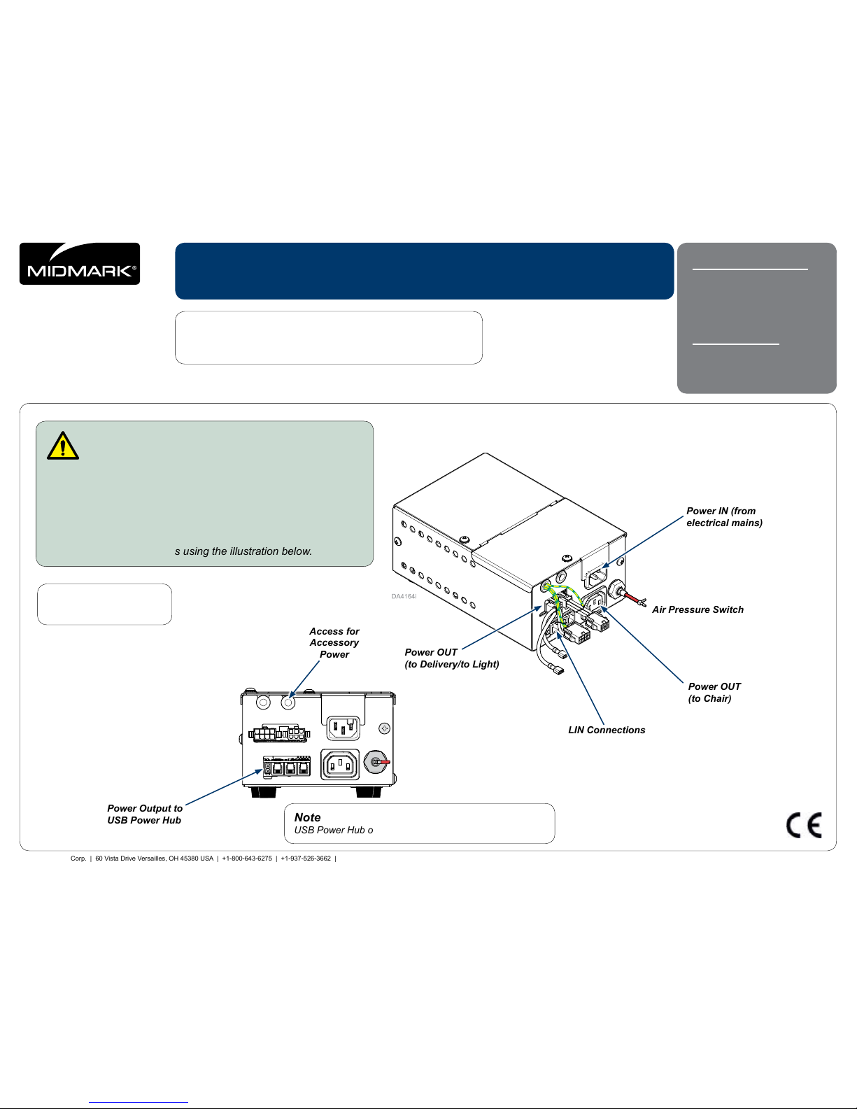
Step 1: Unpack power supply and identify connection
ports.
A) Remove power supply from box.
B) Remove bubble wrap from power supply.
C) Locate connection ports using the illustration below.
Power IN (from
electrical mains)
Power OUT
(to Chair)
Power OUT
(to Delivery/to Light)
LIN Connections
Access for
Accessory
Power
Power Output to
USB Power Hub
Note
153941-002 model shown
Note
USB Power Hub only shown for 153941-001/-002 models.

English - 2
© 2016 Midmark Corp. | 60 Vista Drive Versailles, OH 45380 USA | +1-800-643-6275 | +1-937-526-3662 |
003-2744-99 Rev. E (8/3/16)
TP201 20-42-FO-00013 Rev A1 C2169
Ordering Parts
The following information is required when ordering parts:
Serial number & model number
Part number for desired part
(Refer to Exploded Views and Parts at midmark.com)
Non-warranty parts orders may be faxed to Midmark using the Fax Order
Form in the back of this manual.
For warranty parts orders, call Midmark’s Technical Service Department with
the required information.
Hours: 8:00 am to 5:00 p.m. EST (Monday thru Friday)
Phone: 1-800-Midmark
Calling For Service
Direct all service inquiries to your authorized Midmark dealer. When calling
for service, you must provide the following information:
Model / serial number
Date of purchase
Symptom(s) of malfunction
Authorized EU Representative
Countries in the EU should direct all questions, incidents, and complaints to
Midmark’s Authorized EU representative listed below.
Midmark EMEA Ltd
Beech House
First Floor, East Wing
Ancells Business Park
Fleet
Hampshire GU51 2UN
United Kingdom
Tel: + 44 (0) 1252 360 940
Fax: + 44 (0) 1252 360 941
Disposal of Equipment
At the end of this product’s life, the unit, accessories and other consumable
goods may be contaminated from normal use. Consult local codes and
ordinances for proper disposal of this equipment and other consumable goods.
Electromagnetic Interference
Midmark dental operatory components are designed and built to minimize
electromagnetic interference with other devices. However, if interference is
noticed between another device and this operatory, remove the interfering
device from room and / or plug product into an isolated circuit.
Transportation / Storage / Operating Conditions
Transportation / Storage Temperature: ...........23°F to 100°F (-5°C to 38°C)
Relative Humidity......................................... 10% to 90% (non-condensing)
Atmospheric Pressure .................. 7.2 PSI to 15.3 PSI (50 kPa to 106 kPa)
Operating Temperature Range: ...................... 59°F to 95°F (15°C to 35°C)
Intended Use
The Power Supply is intended to be a non-user-accessible part. It is designed to
deliver electricity at predetermined voltage levels (AC and/or DC) to a Midmark
Dental Chair, Unit, and/or Light.
WARNING
Do not modify this equipment without authorization
of the manufacturer.
English - 3
© 2016 Midmark Corp. | 60 Vista Drive Versailles, OH 45380 USA | +1-800-643-6275 | +1-937-526-3662 |
003-2744-99 Rev. E (8/3/16)
TP201 20-42-FO-00013 Rev A1 C2169
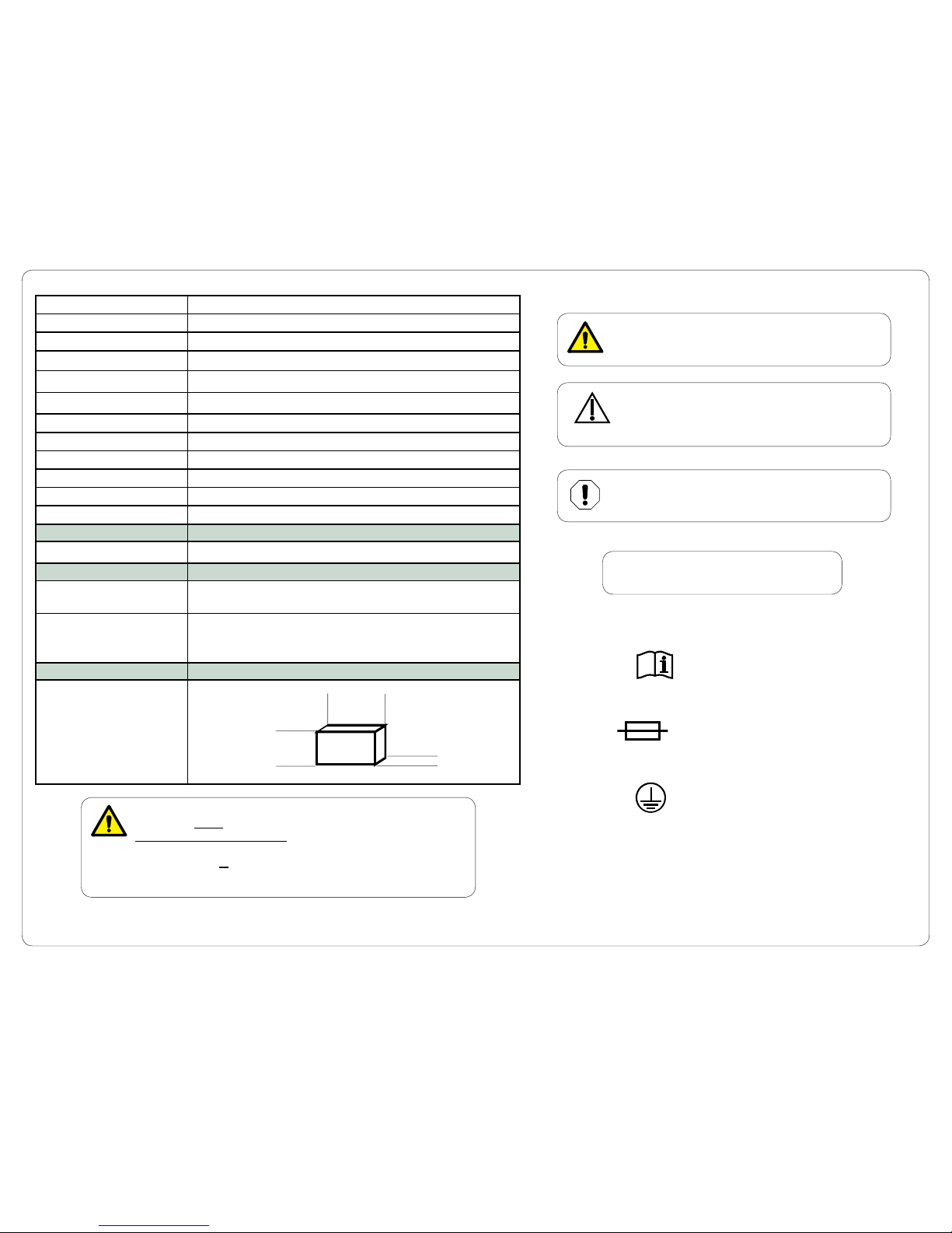
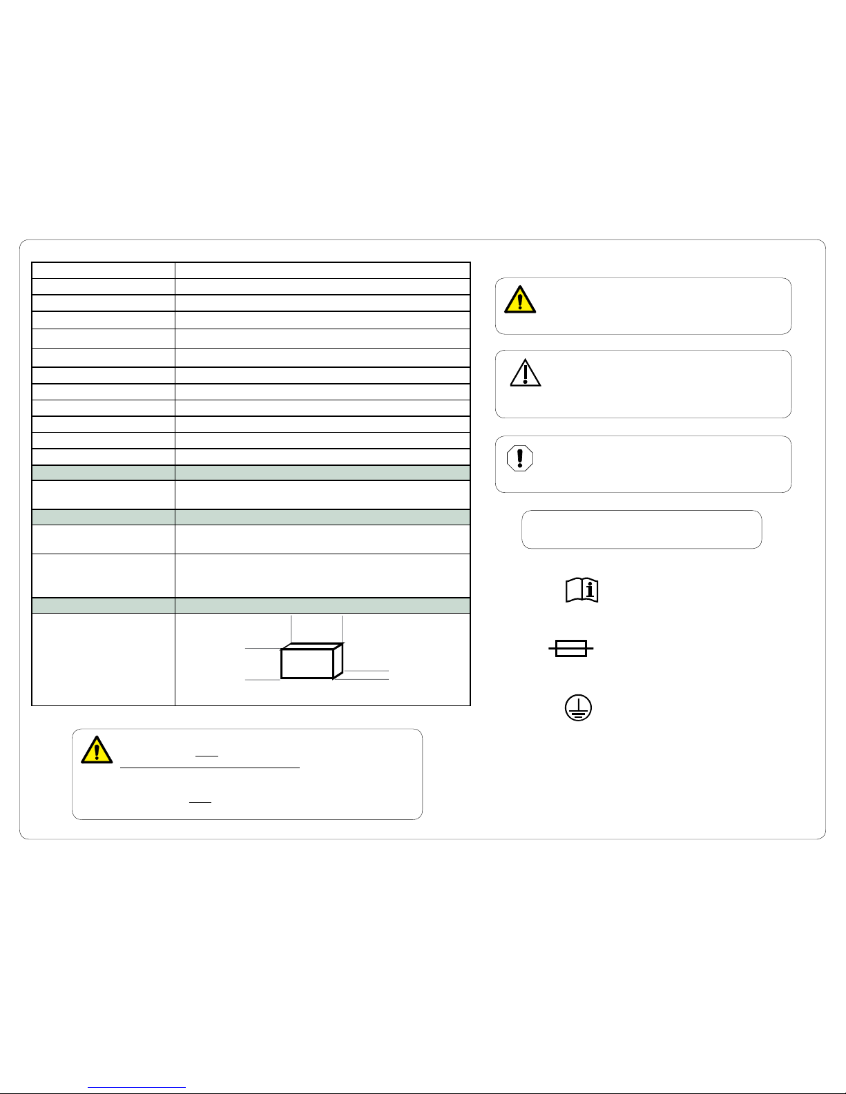
Symbols
WARNING
Indicates a potentially hazardous situation which
could result in serious injury if not avoided.
Equipment Alert
Indicates a potentially hazardous situation which
could result in equipment damage if not avoided.
Caution
Indicates a potentially hazardous situation which may
result in minor or moderate injury if not avoided. It may
also be used to alert against unsafe practices
NOTE
Amplifies a procedure, practice, or condition.
Type T
Fuse
Consult Manuals
Protective
Earth Ground
WARNING
Equipment is not suitable for use in the presence of a
flammable anesthetic mixture with oxygen, air, or nitrous oxide.
Clarification: Equipment is suitable for use in the presence of oxygen,
air, or nitrous oxide.
Electrical Requirements: 115 V~ , 60Hz, 10A
Fuses F1, F2 and F10: F375mAL, 125V~
Fuses F3 and F4: T10AH, 250V~
Fuses F5 and F6: T7AL, 250V~
Fuses F7, F9, F11 and F12: T6.3AL, 250V~
Fuse F8 T6.3AH, 250V~
230V~ , 50/60Hz, 6.3A
Fuses F1, F2 and F10: F375mAL, 125V~
Fuses F3 and F4 : T6.3AH, 250V~
Fuses F5 and F6: T7AL, 250V~
Fuses F7, F9, F11 and F12: T6.3AL, 250V~
Fuse F8 T3.15AH, 250V~
Air Requirements: Maximum 80 -100 PSI (5.52 - 6.9 bar)
Classifications: Class I, Ordinary Equipment (IPX0),
Continuous Operation
Certifications: ES/IEC/EN 60601-1, CAN/CSA C22.2 No. 60601-1 (Safety
Standards)
EN/IEC 60601-1-2 (EMC Standards)
Dimensions:
8.2 in. (20.8 cm.) Long
5.5 in. (14.0 cm.) Wide
3.4 in. (8.6 cm.) High
Long
Wide
High
English - 4
© 2016 Midmark Corp. | 60 Vista Drive Versailles, OH 45380 USA | +1-800-643-6275 | +1-937-526-3662 |
003-2744-99 Rev. E (8/3/16)
TP201 20-42-FO-00013 Rev A1 C2169
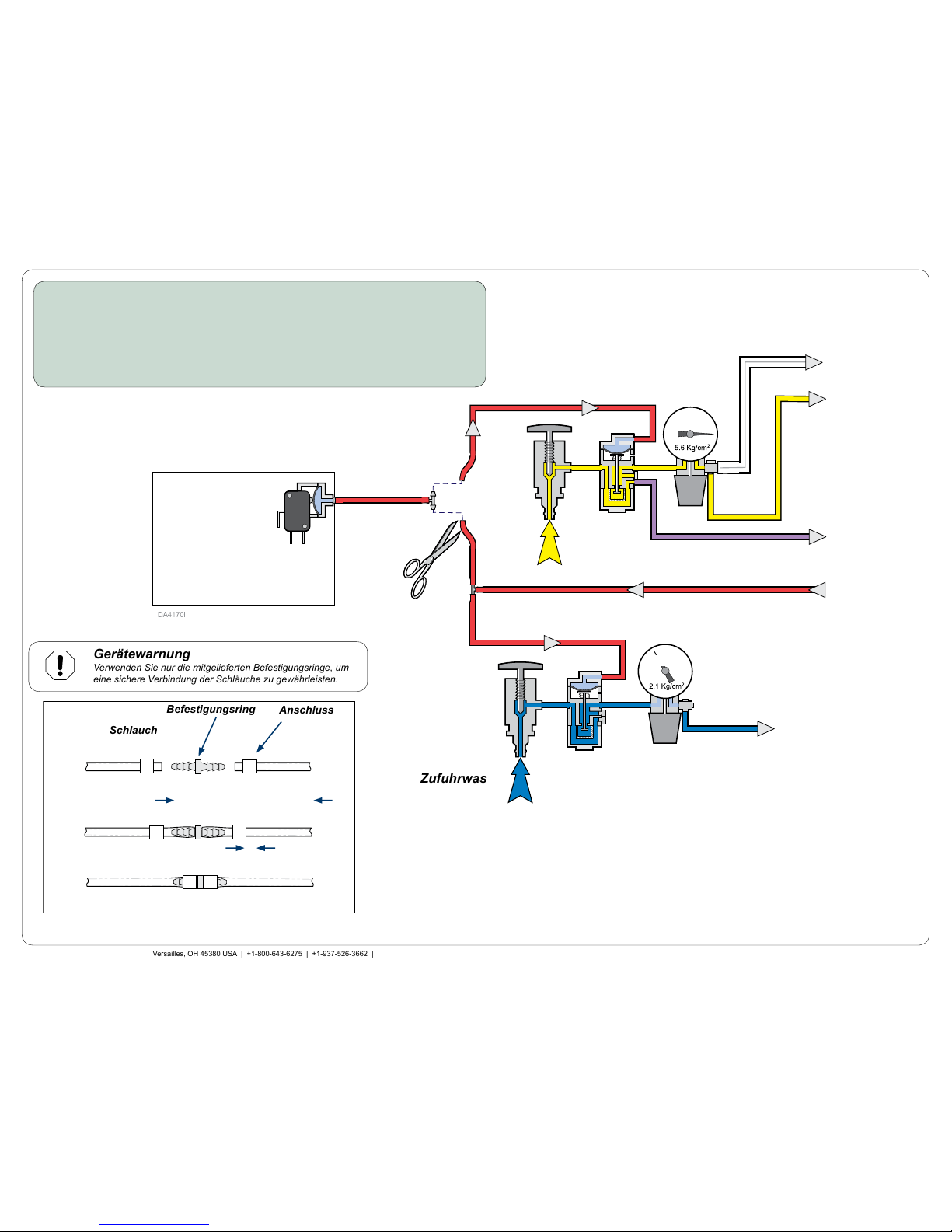
30 PSI
80 PSI
Power Supply
1/8" Red
Supply
Air
Master
Pilot
Shut-off
Master
Pilot
Shut-off
1/8" Blue
1/8" Purple
1/8" or 1/4
Yellow
Air to Master
Switch
1/8" Red
1/8" Red
Air from
Master Switch
Air to Syringe
and Cuspidor
Water to City/Bottle
Toggle Switch
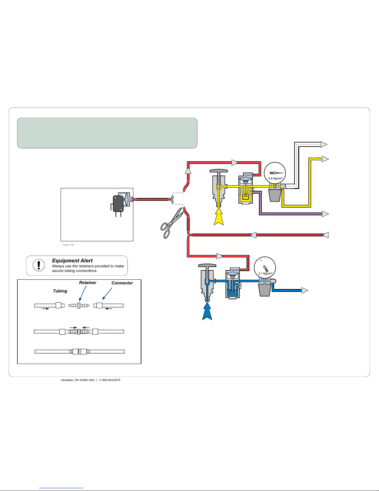
Connector
Retainer
Tubing
Step 2: Splice the power supply’s air pressure switch line into the
master pilot shut-off lines.
A) Connect air pressure switch line to the air supply master pilot shut-off line.
B) Connect air pressure switch line to the water supply master pilot shut-off line.
Supply
Water
Air to Foot
Control
5/16" Clear
Air Pressure
Switch Line
Equipment Alert
Always use the retainers provided to make
secure tubing connections.
English - 5
© 2016 Midmark Corp. | 60 Vista Drive Versailles, OH 45380 USA | +1-800-643-6275 | +1-937-526-3662 |
003-2744-99 Rev. E (8/3/16)
TP201 20-42-FO-00013 Rev A1 C2169
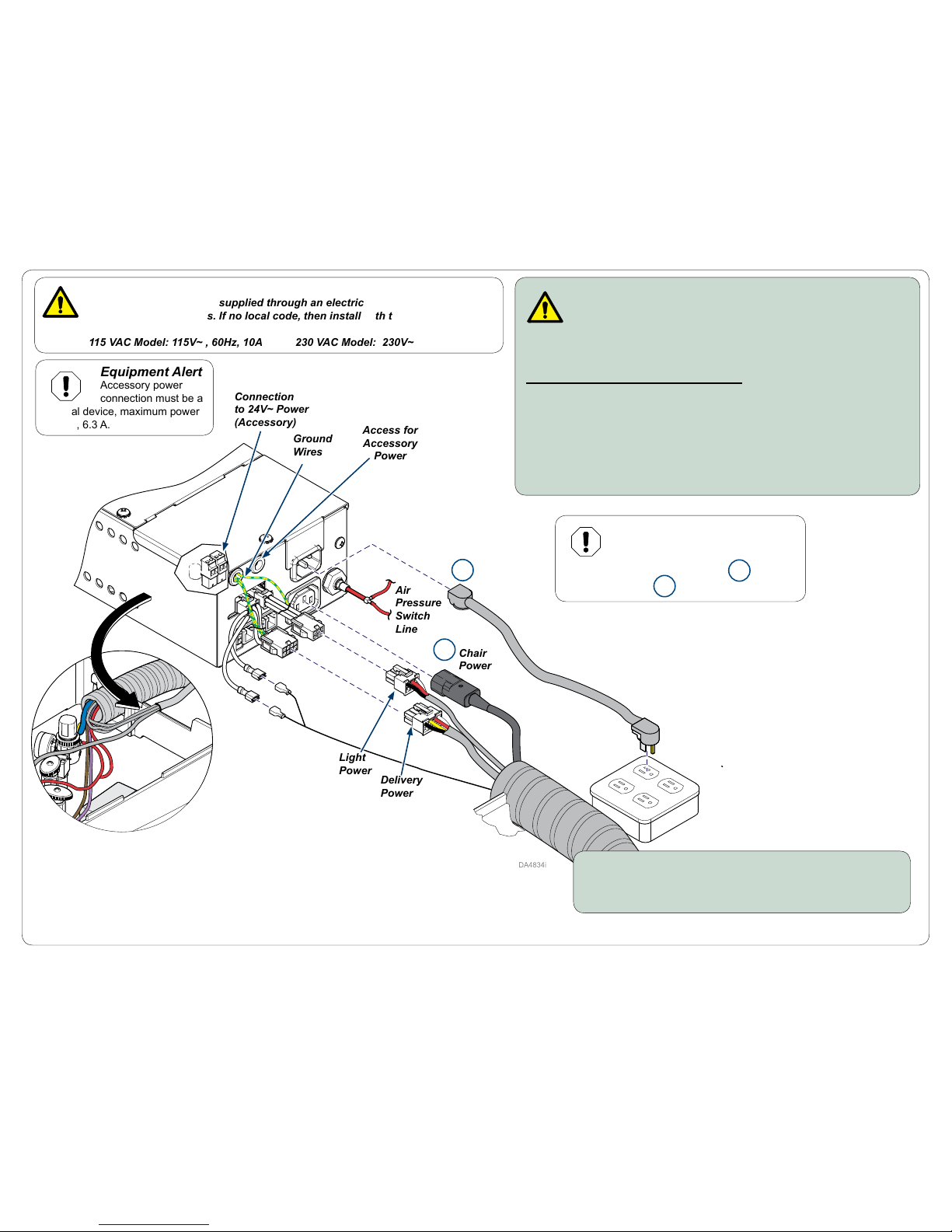
Supply
Power
Cord
Air
Pressure
Switch
Line
Light
Power
Delivery
Power
WARNING
Electrical power must be supplied through an electrical mains receptacle
compliant w/local codes. If no local code, then install with these requirements:
115 VAC Model: 115V~ , 60Hz, 10A 230 VAC Model: 230V~ , 50/60Hz, 6.3A
Electrical Mains
Supply Receptacle
LIN
Connectors
Step 4a: Place power supply in J-box.
A) Position the power supply on floor, in J-box or cabinet,
be careful not to pull or pinch any wires or tubing.
Chair
Power
Ground
Wires
Access for
Accessory
Power
WARNING
Before servicing, disconnect power from the power supply.
Remove the top cover if needed (one screw) then install top
cover after servicing (e.g. replacing fuses, accessing the accessory power
terminals, etc.)
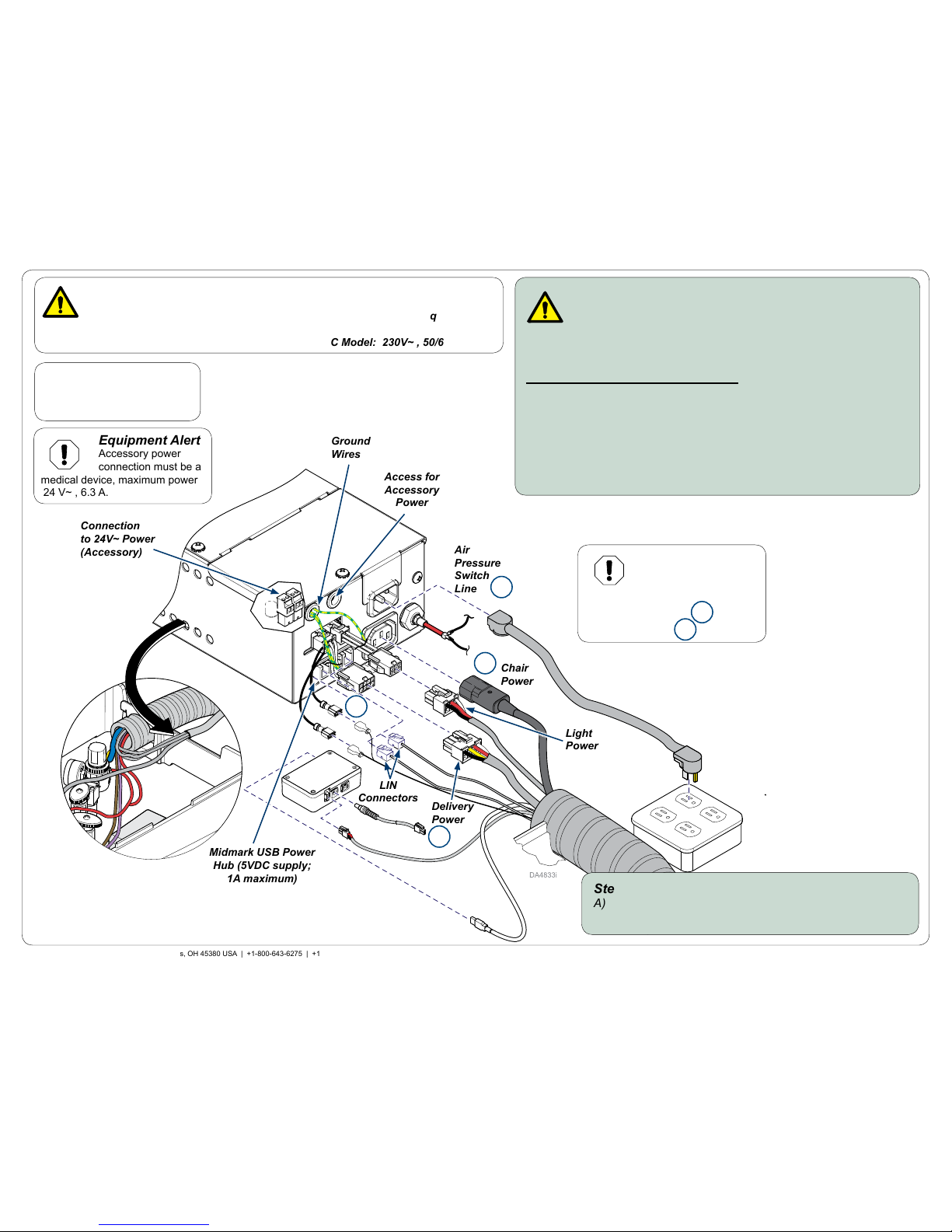
For 153941-001/-002 Models Only:
Step 3a: Make electrical connections to power supply.
A) Connect delivery power to jumper harness shown below.
B) Connect chair power cord.
C) Connect light power (optional) to jumper harness shown below.
D) Connect LIN connector(s).
E) Connect, then plug supply power cord into mains supply receptacle.
F) Secure harnesses with ties as needed.
Equipment Alert
Accessory power
connection must be a
medical device, maximum power
24 V~ , 6.3 A.
Midmark USB Power
Hub (5VDC supply;
1A maximum)
Note
USB Power Hub only shown
for 153941-001/-002 models.
Equipment Alert
230 V~ model requires
air pressure to activate
chair. If air pressure is unavailable,
then plug chair power into
supply power cord .
2
1
3
2
1
3
Connection
to 24V~ Power
(Accessory)
English - 6
© 2016 Midmark Corp. | 60 Vista Drive Versailles, OH 45380 USA | +1-800-643-6275 | +1-937-526-3662 |
003-2744-99 Rev. E (8/3/16)
TP201 20-42-FO-00013 Rev A1 C2169
Supply
Power
Cord
Air
Pressure
Switch
Line
Light
Power
Delivery
Power
WARNING
Electrical power must be supplied through an electrical mains receptacle
compliant w/local codes. If no local code, then install with these requirements:
115 VAC Model: 115V~ , 60Hz, 10A 230 VAC Model: 230V~ , 50/60Hz, 6.3A
Electrical Mains
Supply Receptacle
Step 4b: Place power supply in J-box.
A) Position the power supply on floor, in J-box or cabinet,
be careful not to pull or pinch any wires or tubing.
Chair
Power
Ground
Wires
Access for
Accessory
Power
WARNING
Before servicing, disconnect power from the power supply.
Remove the top cover if needed (one screw) then install top
cover after servicing (e.g. replacing fuses, accessing the accessory power
terminals, etc.)
For 153941-003/-004 Models Only:
Step 3b: Make electrical connections to power supply.
A) Connect delivery power to jumper harness shown below.
B) Connect chair power cord.
C) Connect light power (optional) to jumper harness shown below.
D) Connect LIN connector(s).
E) Connect, then plug supply power cord into mains supply receptacle.
F) Secure harnesses with ties as needed.
Connection
to 24V~ Power
(Accessory)
Equipment Alert
Accessory power
connection must be a
medical device, maximum power
24 V~ , 6.3 A.
Equipment Alert
230 V~ model requires air pressure
to activate chair. If air pressure is
unavailable, then plug chair power into
supply power cord
2
1
2
1

English - 7 English - 7
© 2016 Midmark Corp. | 60 Vista Drive Versailles, OH 45380 USA | +1-800-643-6275 | +1-937-526-3662 |
© 2016 Midmark Corp. | 60 Vista Drive Versailles, OH 45380 USA | +1-800-643-6275 | +1-937-526-3662 |
003-2744-99 Rev. E (8/3/16)
TP201 20-42-FO-00013 Rev A1 C2169
Warranty Information
SCOPE OF WARRANTY
Midmark Corporation (“Midmark”) warrants to the original retail purchaser that it will at Midmark’s option repair or replace components of the dental products manufactured by Midmark
(except for components not warranted under “Exclusions”) that are defective in material or
workmanship under normal use and service. Midmark’s obligation under this limited warranty
is limited to the repair or replacement of the applicable components. This limited warranty
shall only apply to defects that are reported to Midmark within the applicable warranty period
and which, upon examination by Midmark, prove to be defective. This warranty extends only
to the rst retail purchaser of a product and is not transferable or assignable. Replacement
components or products may be used and/or refurbished components or products, provided
they are of like quality and specications as new components or products.
APPLICABLE WARRANTY PERIOD
The applicable warranty period, measured from the date of invoice to the original user, shall
be as follows:
1. OPERATORY PRODUCTS
(a) Two (2) years for all products (except for the items in (b) through (d)).
(b) “KINK-VALVE” module carries a ten (10) year warranty.
(c) The original light bulb on a new light carries a one (1) year warranty.
(d) Accessories not manufactured by Midmark are excluded including
but not limited to Bien Air handpiece systems, Dentsply Cavitron
scaler, Satelec scaler and curing light, and Sopro cameras.
2. ORAL SURGERY PRODUCTS are warranted for a period of one (1) year.
3. STERILIZER PRODUCTS are warranted for a period of one (1) year.
4. ULTRASONIC CLEANER PRODUCTS are warranted for a period of two (2) years.
5. AIR AND VACUUM PRODUCTS
(a) PowerAir® oil-less compressors – Five (5) years or 3,500 hours of use, whichever
occurs rst.
(b) PowerVac® and PowerVac®G dry vacuums – Five (5) years or 10,000 hours of
use, whichever occurs rst (except that the vacuum pump warranty term is ten
(10) years or 20,000 hours of use, whichever occurs rst).
(c) Classic Series® wet-ring vacuums – Five (5) years or 10,000 hours of use, which
ever occurs rst.
(d) PowerMax surgical suction – Two (2) years.
(e) Hg5 Series Amalgam Separator - One (1) year.
(f) Midmark manufactured accessories - One (1) year.
6. INTEGRA™ DENTAL CASEWORK AND ARTIZAN® EXPRESSIONS PRODUCT
(a) Five (5) years for all products and components including door and drawer fronts,
casters and slides, except for the items in (b), (c) and (d).
(b) Three (3) years for electrical components such as task lights/LED lights, cords,
controls and accessories.
(c) Two (2) years for sliding track monitor mount and components and upholstery.
(d) One (1) year for countertops and resin, including accessories.
7. IMAGING PRODUCTS are warranted for a period of two (2) years except for the
ClearVision CR reader which is warranted for a period of one (1) year.
8. MIDMARK Replacement Parts and Accessories carry a ninety (90) day warranty.
EXCLUSIONS
This limited warranty does not cover and Midmark shall not be liable for the following;
(1) defects, damage or other conditions caused, in whole or in part, by misuse, abuse, negligence, alteration, accident, freight damage, negligent storage, tampering or failure to seek
and obtain repair or replacement in a timely manner; (2) products which are not installed,
used, and properly cleaned and maintained as required or recommended in the Midmark
“Installation” and/or “Installation/Operation Manual” for the applicable product, including the
specied structural and operational environment conditions and electrical power requirements; (3) products considered to be of a consumable or sterile nature; (4) accessories
or parts not manufactured by Midmark; (5) charges by anyone for adjustments, repairs,
replacement parts, installation or other work performed upon or in connection with such
products which are not expressly authorized in writing in advance by Midmark; (6) costs and
expenses of routine maintenance and cleaning; (7) representations and warranties made
by any person or entity other than Midmark; (8) matching of color, grain or texture except to
commercially acceptable standards; (9) changes in color caused by natural or articial light;
(10) custom manufactured products; (11) alterations or modications to the product by any
person or entity other than Midmark; and (12) Products that would otherwise be covered
under Sections 1 and 2 of this limited warranty, but are acquired: (i) from a person or entity
that is not Midmark or one of its authorized dealers; or (ii) from a Midmark dealer that is not
authorized to sell the product at issue in the geographic territory where the purchaser is
located, or is not authorized to sell the product at issue within the medical, animal health or
dental market, as the case may be, in which purchaser intends to use the product.
EXCLUSIVE REMEDY; CONSEQUENTIAL DAMAGES DISCLAIMER
MIDMARK’S ONLY OBLIGATION UNDER THIS LIMITED WARRANTY IS THE REPAIR OR
REPLACEMENT OF DEFECTIVE PARTS. MIDMARK SHALL NOT BE LIABLE FOR AND
HEREBY DISCLAIMS ANY DIRECT, SPECIAL, INDIRECT, INCIDENTAL, EXEMPLARY OR
CONSEQUENTIAL DAMAGES OR DELAYS, INCLUDING, BUT NOT LIMITED TO, DAMAGES FOR LOSS OF PROFITS OR INCOME, LOSS OF USE, DOWNTIME, COVER AND
EMPLOYEE OR INDEPENDENT CONTRACTOR WAGES, PAYMENTS AND BENEFITS.
WARRANTY DISCLAIMER
THIS LIMITED WARRANTY IS MIDMARK’S ONLY WARRANTY AND IS IN LIEU OF ALL
OTHER WARRANTIES, EXPRESS OR IMPLIED. MIDMARK MAKES NO IMPLIED WARRANTIES OF ANY KIND INCLUDING ANY IMPLIED WARRANTIES OF MERCHANTABILITY OR FITNESS FOR A PARTICULAR PURPOSE. THIS WARRANTY IS LIMITED TO THE
REPAIR OR REPLACEMENT OF DEFECTIVE PARTS.
STATUTE OF LIMITATIONS
No action may be brought against Midmark for breach of this limited warranty, or implied
warranty, if any, or for any other claim arising out of or relating to the products, more than
ninety (90) days following expiration of the limited warranty period.

Deutsch - 1
TP201 20-42-FO-00013 Rev A1 C2169
© 2015 Midmark Corp. | 60 Vista Drive Versailles, OH 45380 USA | +1-800-643-6275 | +1-937-526-3662 |
midmark.com
Gültig für die Modelle:
153941-001 (115V mit USB)
153941-002 (230V mit USB)
153941-003 (115V)
153941-004 (230V)
Sonderwerkzeuge:
keine
Ausgangssprache: Englisch
Hinweis
Die Stromversorgungsgeräte sind in den Modellen mit 115 V~ und 230 V~ erhältlich.
Sicherstellen, dass die installierten Modelle der Netzstromversorgung entsprechen.
Installation: Netzteil-Modell 153941
Luftdruckschalter
ACHTUNG!
Vor Wartungsarbeiten den Strom vom Netzteil trennen.
Die obere Abdeckung nach den Wartungsarbeiten (z. B.
Austausch von Sicherungen, Zugriff auf die Zubehörklemmen usw.)
wieder anbringen.
Schritt 1: Netzteil auspacken und die Anschlussports
suchen.
A) Das Netzteil aus der Kiste nehmen.
B) Die Luftpolsterfolie vom Netzteil entfernen.
C) Die Anschlussports mithilfe der Abbildung unten auffinden.
Strom EIN
(vom Stromnetz)
Strom AUS
(zum Stuhl)
Strom AUS (zu Dental-
system/Beleuchtung)
LIN-Anschlüsse
Zugang für
Zubehör-
strom
Stromabgabe zum
USB-Power-Hub
Hinweis
Das Modell 153941-002
wird dargestellt.
Hinweis
USB-Power-Hub wird nur für die Modelle 153941-001/-002 dargestellt.
003-2744-99 Rev. E (8/3/16)

Deutsch - 2
© 2016 Midmark Corp. | 60 Vista Drive Versailles, OH 45380 USA | +1-800-643-6275 | +1-937-526-3662 |
003-2744-99 Rev. E (8/3/16)
TP201 20-42-FO-00013 Rev A1 C2169
Bestellen von Ersatzteilen
Zur Bestellung von Ersatzteilen sind folgende Informationen erforderlich:
Seriennummer & Modellnummer
Teilenummer für das gewünschte Teil
(Siehe Explosionszeichnungen und Teile bei midmark.com)
Bestellungen von Teilen ohne Garantie können an Midmark gefaxt werden,
unter Verwendung des Fax-Bestellformulars am Ende dieses Handbuchs.
Für Bestellungen von Garantieteilen ist die technische Serviceabteilung
anzurufen, der die erforderlichen Angaben mitzuteilen sind.
Geschäftsstunden: 8:00 bis 17:00 Uhr EST (14:00 bis 23:00 Uhr MEZ)
(Montag bis Freitag)
Telefon: +1-937-526-3662
Serviceanfragen
Bei allen Servicefragen ist der Midmark-Vertragshändler zu kontaktieren. Bei
allen Serviceanfragen sind die folgenden Informationen anzugeben:
Modell-/Seriennummer
Kaufdatum
Symptom(e) der Fehlfunktion
Autorisierter EU-Vertreter
Wenn das betreffende Land Mitglied der EU ist, sind alle Fragen, Vorfälle
oder Beschwerden an den folgenden autorisierten EU-Vertreter von Midmark
zu richten.
Midmark EMEA Ltd
Beech House
First Floor, East Wing
Ancells Business Park
Fleet
Hampshire GU51 2UN
Großbritannien
Tel.: + 44 (0) 1252 360 940
Fax: + 44 (0) 1252 360 941
Geräteentsorgung
Es ist möglich, dass das Gerät selbst, dessen Zubehör sowie andere Verbrauchsgüter am Ende des Produktlebenszyklus durch den normalen Betrieb
verunreinigt sind. Daher die örtlichen Verordnungen und Bestimmungen zur
ordnungsgemäßen Entsorgung dieses Geräts und anderer Verbrauchsgüter
beachten.
Elektromagnetische Störungen
Die zahnärztlichen Behandlungskomponenten von Midmark wurden so
konstruiert, dass elektromagnetische Interferenzen mit anderen Geräten
weitgehend ausgeschlossen sind. Sollten zwischen diesem Praxisgerät und
einem anderen Gerät jedoch trotzdem elektromagnetische Interferenzen
auftreten, so sollte das die Störung verursachende Gerät aus dem Raum entfernt
und/oder das Gerät an einen isolierten Stromkreis angeschlossen werden.
Transport-/Lager-/Betriebsbedingungen
Transport-/Lagertemperatur: ....................–5 °C bis 38 °C (23°F bis 100°F)
Relative Luftfeuchtigkeit ....................10 % bis 90 % (nicht kondensierend)
Atmosphärischer Druck ............. 50 kPa bis 106 kPa (7,2 PSI bis 15.3 PSI)
Betriebstemperaturbereich: .........................15°C bis 35°C (59°F bis 95°F)
Zweckbestimmung
Das Netzteil darf nicht vom Benutzer geöffnet werden. Es liefert Elektrizität mit
festgelegten Wechsel- und/oder Gleichspannungen an den Stuhl, das Dentalsystem und/oder die Beleuchtung von Midmark.
ACHTUNG!
Dieses Gerät darf ohne Genehmigung des
Herstellers nicht modifiziert werden.
Deutsch - 3
© 2016 Midmark Corp. | 60 Vista Drive Versailles, OH 45380 USA | +1-800-643-6275 | +1-937-526-3662 |
003-2744-99 Rev. E (8/3/16)
TP201 20-42-FO-00013 Rev A1 C2169
Symbole
ACHTUNG!
Weist auf eine möglicherweise gefährliche Situati-
on hin, die zu schweren Verletzungen führen kann,
wenn keine Vorsichtsmaßnahmen getroffen werden.
Gerätewarnung
Weist auf eine möglicherweise gefährliche Situation
hin, die zu Sachschäden führen kann, wenn keine
Vorsichtsmaßnahmen getroffen werden.
Vorsicht
Weist auf eine möglicherweise gefährliche Situation hin,
die zu leichten oder mittelschweren Verletzungen führen
kann, wenn keine Vorsichtsmaßnahmen getroffen werden. Dieses
Symbol kann auch auf unsichere Praktiken aufmerksam machen
HINWEIS
Hebt Vorgänge, Verfahren oder Bedingungen hervor.
Sicherung
Typ T
In den Handbüchern
nachschlagen
Schutzerdung
ACHTUNG!
Dieses Gerät ist nicht für den Einsatz in Gegenwart eines
entflammbaren Narkosemittelgemischs mit Sauerstoff, Luft oder
Stickstoffoxid geeignet.
Erläuterung: Das Gerät kann in Gegenwart von Sauerstoff, Luft oder
Stickstoffoxid verwendet werden.
Elektrische Anforderungen: 115 V~, 60 Hz, 10 A
Sicherungen F1, F2 und F10: F 375 mAL, 125 V~
Sicherungen F3 und F4: T 10 AH, 250 V~
Sicherungen F5 und F6: T 7 AL, 250 V~
Sicherungen F7, F9, F11 und F12: T 6,3 AL, 250 V~
Sicherung F8 T 6,3 AH, 250 V~
230 V~ , 50/60 Hz, 6,3 A
Sicherungen F1, F2 und F10: F 375 mAL, 125 V~
Sicherungen F3 und F4: T 6,3 AH, 250 V~
Sicherungen F5 und F6: T 7 AL, 250 V~
Sicherungen F7, F9, F11 und F12: T 6,3 AL, 250 V~
Sicherung F8 T 3,15 AH, 250 V~
Voraussetzungen für
Luftzufuhr:
Maximal 5,52–6,9 bar (80–100 PSI)
Klassifizierungen: Klasse I, Standardgerät (IPX0),
Dauerbetrieb
Zertifizierungen: ES/IEC/EN 60601-1, CAN/CSA C22.2 Nr. 60601-1
(Sicherheitsnormen)
EN/IEC 60601-1-2 (EMV-Normen)
Abmessungen:
20,8 cm (8,2 Zoll) lang
14,0 cm (5,5 Zoll) breit
8,6 cm (3,4 Zoll) hoch
Lang
Breit
Hoch
Deutsch - 4
© 2016 Midmark Corp. | 60 Vista Drive Versailles, OH 45380 USA | +1-800-643-6275 | +1-937-526-3662 |
003-2744-99 Rev. E (8/3/16)
TP201 20-42-FO-00013 Rev A1 C2169
30 PSI
80 PSI
Netzteil
0,32 cm (1/8“) Rot
Zufuhr-
luft
Hauptsteuer-
absperrung
Hauptsteuer-
absperrung
0,32 cm
(1/8“)
Blau
0,32 cm (1/8”) Violett
0,32 cm oder
0,64 cm (1/8
oder 1/4“)
Gelb
Luft zu
Hauptschalter
0,32 cm (1/8“) Rot
0,32 cm (1/8“) Rot
Luft von
Hauptschalter
Luft zu Spritze und
Speischale
Wasser zu
Stadt/FlaschenKippschalter
Anschluss
Befestigungsring
Schlauch
Schritt 2: Verbinden Sie die Druckluftschalterleitung des Netzteils
mit den Hauptsteuerabsperrleitungen.
A) Die Druckluftschalterleitung an die Hautsteuerabsperrleitung der Luftzufuhr
anschließen.
B) Die Druckluftschalterleitung an die Hautsteuerabsperrleitung der
Wasserzufuhr anschließen.
Zufuhrwasser
Luft zu
Fußsteuerung
Luftdruckschalterleitung
Gerätewarnung
Verwenden Sie nur die mitgelieferten Befestigungsringe, um
eine sichere Verbindung der Schläuche zu gewährleisten.
0,79 cm (5/16“)
Saubere
 Loading...