

Midland Precision 4001 Owner's Manual

2
How to install your Midland mobile CB .................................. 3
Installation and operating accessories furnished with your Midland
CB: ................................................................................................... 3
Where to locate your CB transceiver. ............................................... 3
Mechanical mounting. ...................................................................... 4
Power wiring ( negative ground only). .............................................. 5
Mounting the main unit. .................................................................... 5
Installation of microphone hanger. ................................................... 6
Antenna: ................................................................................... 6
How to select, position install and tune the right one for you. .......... 6
Antenna installation. ......................................................................... 7
Tuning your antenna. ....................................................................... 7
Factors affecting CB range ..................................................... 7
Noise: ........................................................................................ 7
Midland MODEL 4001 CB Operating controls ....................... 8
FRONT PANEL CONTROLS .................................................... 8
BACK PANEL ......................................................................... 10
HOW TO OPERATE YOUR TRANSCEIVER .......................... 10
TECHNICAL SPECIFICATIONS ............................................. 10
GENERAL ...................................................................................... 10
TRANSMITTER .............................................................................. 11
SERVICE ................................................................................. 11
LIMITED WARRANTY. ............................................................ 12
Midland MODEL 4001 40 Channel mobile citizens band
transceiver
For your protection, the space below is provided for you to record the Serial
Number of this product, which is located on the rear of the radio. After
recording this number, keep this record for future reference along with the
sales receipt. The sales receipt is needed should your radio ever need
service.
FCC I.D. MMA4001
Serial Number:____________________

3
Welcome to the world
of Midland electronics
Congratulations. You have just purchased a state of the art mobile CB radio.
In the years ahead, you can expect to realize-time and again the real
reasons and meaning of the front running position Midland holds among CB
users everywhere. You will come to know that Midland power is more than
just a slogan, but the heading of long list of hearable, seeable benefits. As
your Midland CB experience unfolds and grows we hope you will remember
that CB is only one kind of electronic excellence available under the Midland
name.
Your 40 channel CB represents the state of the art in high tech engineering.
The unit incorporates microprocessor controlled PLL circuitry for precise
tuning.
How to install your Midland mobile CB
This transceiver may be installed in any 12-volt negative groundsystem car or truck. Most current U.S. and foreign vehicles use a negative
system, but some older models and some newer large trucks may have a
positive ground.
Check the requirements for your vehicle before you begin
installation.
Generally, you have a negative-ground system if the minus ( - )
battery terminal is connected to the motor block. Contact your dealer in the
event you are unable to determine your vehicle’s polarity system.
Installation and operating accessories furnished with your
Midland CB:
1. Easy removal mounting bracket system.
2. Microphone bracket system.
3. All main-unit and microphone mounting hardware needed for normal
installation.
4. Plug-in microphone with coil cord.
5. FCC part 95, Subpart D.
6. Owner’s Manual.
Where to locate your CB transceiver.
Your new Midland CB is designed to be installed under the dash or
vertically on a console of your vehicle.
Safety and convenience are the primary considerations in deciding
exactly where to locate your radio.
Caution: Be sure that the unit is located so that it does not interfere with the
driver, supplemental restraint systems (air bags), or impair access to any
controls. Connecting cables must be routed and secured in such a manner
as not to interfere with the operation of the brake, accelerator or other
controls. Interference from either the unit or connecting cables may
contribute to the loss of control of the vehicle.
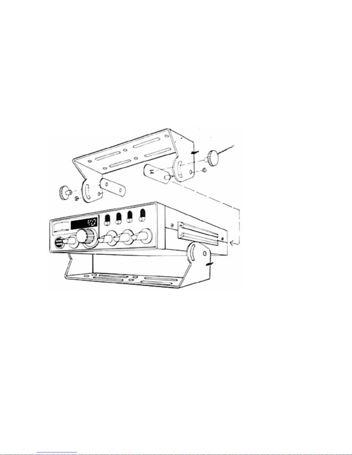
Mechanical mounting.
Step 1: Heeding the caution, use the mounting bracket as a template for
marking the location of screw holes under the dash. Use an awl, nail or
other sharp pointed object to mark the hole locations.
Step 2: Drill a 1/8” hole for each screw hole in the mounting bracket. Attach
the bracket to the dash with the Phillips head sheet metal screws provided.
, Extreme care should be exercised when drilling into the dash to avoid damage to
under-dash electronic ignition, cruise control, instrument and / or accessory
wiring.
Step 3: Attach removable 3-pin plug-in DC cord to polarized DC jack on the
rear of the transceiver.
4
 Loading...