

Page 1

MXT400
Owners
Manual
Page 2

Model MXT400
Model MXT400
CONTENTS
FEATURES .............................................................................4
FCC NOTICE .........................................................................5
Exposure To Radio Frequency Energy......................5
INSTALLING YOUR RADIO
Preparation for Installation.........................................................6
Installing the Mounting Bracket .................................................7
Installing the Antenna ................................................................ 8
Electrical and Rear Panel Connections .....................................9
Connecting the Microphone.......................................................9
Using an External Speaker ......................................................10
CONTROLS AND INDICATORS
Operating Controls...................................................................10
LCD Display............................................................................. 11
Microphone Controls................................................................11
Rear Panel Connections..........................................................12
OPERATING YOUR RADIO
About Range............................................................................13
Power On/O ...........................................................................14
Selecting the Active Channel ...................................................14
Transmitting and Receiving a Call ...........................................14
Locking the Keypad..................................................................15
Using Monitor Mode ................................................................15
Scanning for Active Channels..................................................16
Call Alert ..................................................................................16
UTILITY FUNCTIONS
Selecting a Privacy Code.........................................................17
Selecting the Transmit (TX) Power Level ................................18
“MENU”MODE FUNCTIONS
Transmit (TX) Function ............................................................19
Talk Around (Talk) Function .....................................................19
Voice Compander (Comp) Function ........................................20
Silent Operation (Mute) Function.............................................20
Call Alert (Call) Function ..........................................................20
Time Out Timer (TOT) Function ...............................................21
Auto Power-O (APO) Function .............................................21
Squelch Sensitivity ..................................................................22
Display Brightness ...................................................................22
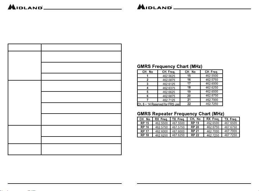
Repeater Channels..................................................................22
Restoring The Default Settings ................................................23
CARE AND MAINTENANCE ...........................................23
TROUBLESHOOTING GUIDE .........................................24
SPECIFICATIONS ..............................................................25
ACCESSORIES ...................................................................28
FCC WARNINGS & STATEMENTS..............................29
WARRANTY...........................................................................30
Page 2
midlandusa.com
midlandusa.com
Page 3
Page 3

Model MXT400
Model MXT400
WELCOME TO THE WORLD OF MIDLAND RADIO
Congratulations on your purchase of a high quality MIDLAND product.Your
MXT400 2-way radio represents state-of-the-art high tech engineering.
Designed for General Mobile radio Service (GMRS) operation, this
compact package is big on performance. It is a quality piece of electronic
equipment, skillfully constructed with the nest components. The circuitry
is all solid-state and mounted on a rugged printed circuit board. Your
MXT400 radio is designed for reliable and trouble-free performance for
years to come.
FEATURES
– 15 GMRS Channels
– 8 Repeater Channels
– 142 Privacy Codes (38 CTCSS / 104 DCS)
– Monitor Function
– Scan Function
– Keypad Lock
– Power Hi/Mi/Lo Settings
– External Speaker Jack
Page 4
midlandusa.com
FCC NOTICE
The MXT400 operates on GMRS (General Mobile Radio Service)
frequencies, which require a Federal Communications Commission
(FCC) license. You must be licensed prior to operating on channels 1-7,
15-22 or RP15-22, which comprise the GMRS channels of the MXT400.
Serious penalties may result from unlicensed use of GMRS channels, in
violation of FCC rules, as stipulated in the Communications Act’s Sections
501 and 502 (amended). You will be issued a call sign by the FCC that
should be used for station identication when operating your radio on
GMRS channels. You should also cooperate by engaging in permissible
transmissions only, avoiding channel interference with other GMRS users,
and being prudent with the length of your transmission time.
To obtain a license or ask questions about the license application, contact
the FCC at 1-888-CALL FCC or go to the FCC’s website:
http:// www.fcc.gov and request form 605.
Exposure To Radio Frequency Energy
Your Midland radio is designed to comply with the following national and
international standards and guidelines regarding exposure of human
beings to radio frequency electromagnetic energy.
▪ United States Federal Communications Commission, Code of Federal
Regulations: 47 CFR part 2 sub-part J
▪ American National Standards Institute (ANSI)/Institute of Electrical &
Electronics Engineers (IEEE) C95. 1-1992
▪ Institute of Electrical and Electronics Engineers (IEEE) C95. 1-1999 Edition
▪ National Council on Radiation Protection and Measurements (NCRP) of
the United States, Report 86, 1986
▪ International Commission on Non-lonizing Radiation Protection (ICNIRP)
1998
▪ To control your exposure and ensure compliance with the general popu-
lation or uncontrolled environment exposure limits, transmit no more than
50% of the time. The radio generates measurable RF energy exposure
only when transmitting.
▪ The consumer must maintain a minimum safe separation distance of 23.6
inches (60 cm) from the antenna when transmitting.
midlandusa.com
Page 5
Page 4
Model MXT400
Model MXT400
INSTALLING YOUR RADIO
Preparation for Installation
This radio may be installed in any 12-volt negative ground system vehicle.
Most current U.S. and Foreign vehicles use a negative ground system,
but some older models and some newer large trucks may have a positive
ground. Check the specications for your vehicle before beginning
installation. Generally, you have a negative-ground system if the negative
(-) battery terminal is connected to the motor block. Contact your dealer if
you are unable to determine your vehicle’s polarity system.
1. Read these instructions completely before beginning installation.
2. Read and follow all safety precautions in your vehicle’s Service Manual.
3. Make sure all necessary tools, materials, and parts are on hand.
4. Disconnect the negative (-) battery cable before installing your radio. Be
sure to reconnect the cable when installation is complete.
5. Determine a mounting location for your radio. Choose a location that does
not impair visibility or interfere with driving. Also take into consideration
the routing and length of the lead wires and cables to the power source,
antenna, and/or optional external speaker.
CAUTION: Extreme care should be exercised when drilling into
the dash to avoid damage to under dash electronic ignition,
cruise control, instrument and/or accessory wiring.
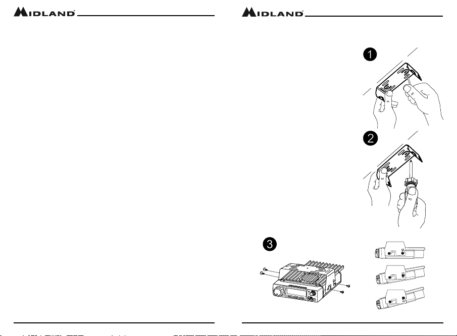
Installing the Mounting Bracket
1. Using the mounting bracket as a
template, mark the location of each
screw hole. Use a nail or other sharp
pointed object to mark the hole
locations.
2. Attach the bracket with the supplied
self-tapping screws. Tighten
the screws securely. DO NOT
OVER-TIGHTEN.
3. Determine the best suited position
for using the radio, then insert and
tighten the supplied SEMS screws.
Page 6
midlandusa.com
midlandusa.com
Page 7
Page 5
Model MXT400
Model MXT400
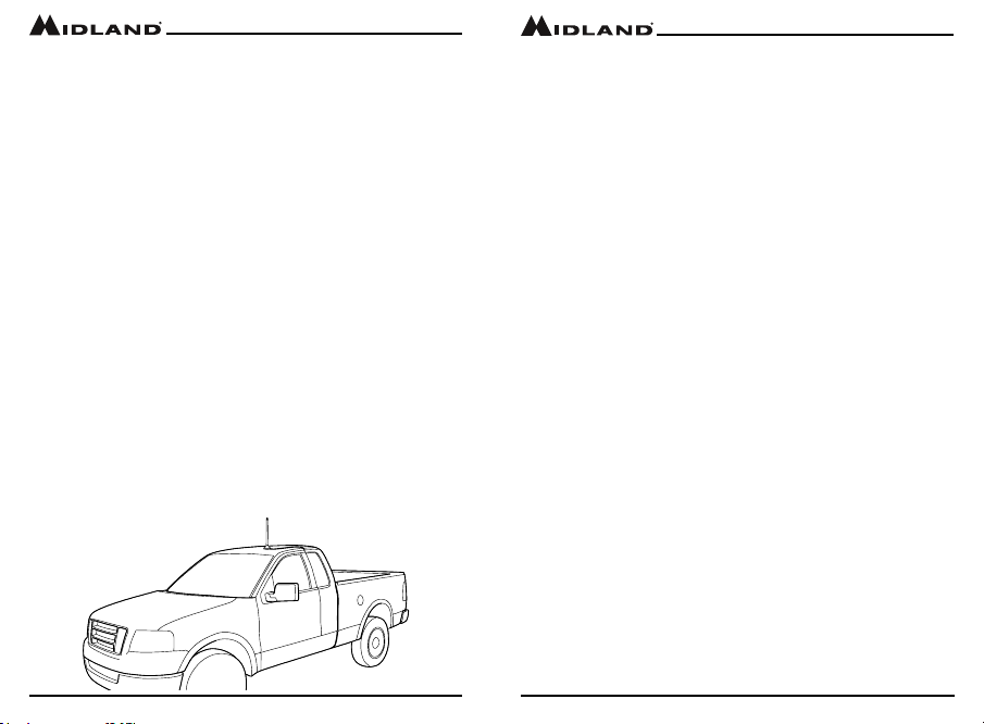
Installing the Antenna
To get the best range from the MXT400 an external antenna (50Ω) should
be used. The antenna is intended to be attached to the vehicle’s roof,
trunk or similar location. Specic installation requirements vary between
vehicles. Use the following guidelines to install the antenna.
*Where you locate your antenna does make a dierence.*
1. Metal surfaces covered by berglass or vinyl may aect radio range.
Avoid these locations.
2. Mount the antenna as high on the vehicle as possible. The higher the
better.
3. If possible, mount the antenna in the center of whatever surface you
choose.
4. The antenna cable is 19.7 feet (6 meters) long. Be sure the mounting
location will allow for connection of the cable to the radio.
5. Be sure the mounting location is clean and dry before installing the
antenna.
6. Route the antenna cable through an accessible entry point, such as a
rear door or trunk opening.
7. When routing the antenna cable inside the vehicle, keep the cable
away from noise sources, such as the ignition system, gauges, etc.
8. Exercise care to prevent cable damage. Make use of existing gaskets,
grommets and weather stripping to protect the cable along its route.
Page 8
midlandusa.com
Electrical and Rear Panel Connections
Refer to Rear Panel Connections for rear panel connector locations.
NOTE: Radio antenna is installed separately.
Connecting the Radio to a Power Source
1. Connect the positive lead (RED wire with in-line fuse holder) to either
(a) the fuse block or (b) directly to the positive post of the vehicle’s
battery.
NOTE: The fuse block is usually the most convenient connection point.
The power cord positive lead can also be connected to the Accessory
terminal on the fuse block or ignition switch, so the radio automatically
turns o when the ignition is turned o.
2. Tightly connect the ground lead (BLACK wire) directly to the vehicle’s
metal frame. A good direct metal-to-metal ground is essential for optimum performance.
Connecting the Microphone
Insert the RJ45 connector into the front of the MXT400. To remove, lightly
pinch the bottom region of the boot assembly of the Microphone and gently
pull towards you.
The microphone bracket can then be attached to the vehicle dash or other
convenient location in a manner similar to the mounting bracket.
midlandusa.com
Page 9
Page 6
Model MXT400
Using an External Speaker
The MXT400 provides a rear-panel jack for connection of an optional
external speaker (sold separately).
When selecting an external speaker, ensure the speaker has 8-ohm
impedance and is rated for 4.0 watts.
NOTE: When an external speaker is connected, the radio’s internal
speaker is automatically disabled.
Model MXT400
LCD Display
CONTROLS AND INDICATORS
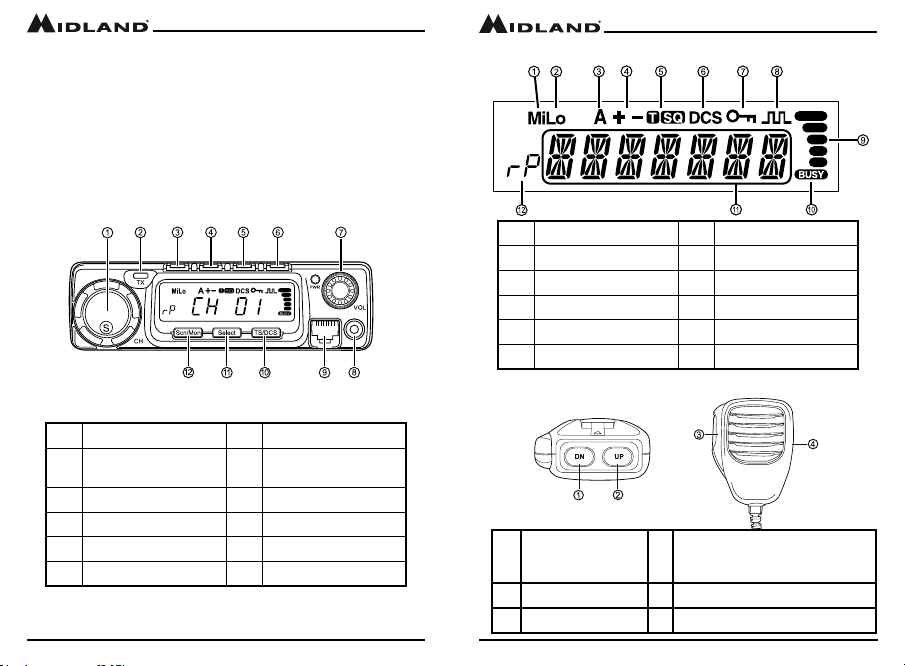
Operating Controls
1 Channel 7 Volume
2 TX Indicator 8
3 Menu 9 Mic connector
4 Call/Lock 10 Privacy Tone
5 Power Level 11 Select
6 Power On/O 12 Scan/Monitor
Page 10
Data Terminal - not used
in the MXT400
midlandusa.com
1 Medium Power 7 Keypad Lock
2 Low Power 8 Compander
3 Auto Power O 9 Signal Strength
4 Repeater Oset 10 Receiver Active
5 CTCSS Privacy Tone 11 Channel Name
6 DCS Privacy Tone 12 Repeater Channel
Microphone Controls
4 Lock Switch - slide the swith down
1. Channel Down
2. Channel Up
3. PTT (Push to Talk)
midlandusa.com
to lock all of the buttons on the mic
except the PTT
Page 11
Page 7
Model MXT400 Model MXT400
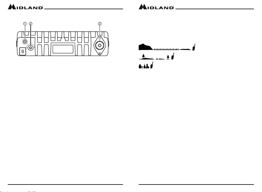
Rear Panel Connections
1. External Power Jack - Connection Terminal for optional power cable
(sold seperately).
2. EXT SPKR Jack - 3.5mm Audio connector for optional external speaker
(sold seperately) (see Using an External Speaker for specications).
3. ANT Jack - SO-239 UHF connector for external antenna (sold seperately)
OPERATING YOUR RADIO
About Range
Your MXT400 is designed to give you maximum operating range under
optimum conditions.
Maximum Range / No Sight Obstruction
Medium Range / Partial Obstruction to Line of Sight
Short Range / Major Obstruction to Line of Sight
Optimum conditions for maximum operating range are:
▪ Over water
▪ In open rural areas without obstructions
▪ On at areas where you can see the other radio user
To ensure you get maximum range:
▪ Be sure to mount the antenna (sold seperately) as high as possible
on your vehicle
▪ Be sure to set your radio to use Hi power (see Selecting the
Transmit (TX) Power Level)
Page 12 Page 13
midlandusa.com midlandusa.com
Page 8

Model MXT400
Power On/O
To turn the radio on and o:
1. With the radio o, quickly press and release the Power On/O button to
turn the radio on.
▪ The LCD display will display the Midland welcome screen and then
display the most recently selected channel.
2. With the radio on, press and hold the Power On/O button to turn the
radio o.
▪ The LCD display will go blank when the radio turns o.
Selecting the Active Channel
IMPORTANT! To communicate between two MXT400 radios or any GMRS
radio, both radios must be set to the same channel and Privacy Code (see
Selecting a Privacy Code) selections.
To select the active channel:
1. Be sure the radio is turned on (see Power On/O)
2. Rotate the Channel Knob clockwise to scroll forward through the
available channels. Rotate the Channel Knob counter-clockwise to
scroll backward through the available channels.
▪ The Channel icon on the LCD display will show the currently
selected channel.
Transmitting and Receiving a Call
IMPORTANT! To communicate between two MXT400 radios or any GMRS
radio, both radios must be set to the same channel and Privacy Code.
To transmit and receive a call:
1. Be sure the radio is turned on (see Power On/O)
2. To transmit a call, press and hold the PTT button on the microphone,
and speak into the microphone in a normal voice.
NOTE: For maximum clarity, hold the microphone 2 to 3 inches from your
mouth when speaking.
Model MXT400
▪ The TX Indicator will show continuously on the LCD display while
transmitting.
3. To receive a call, release the PTT button on the microphone.
▪ The Busy icon will show on the LCD display when your radio is
receiving a transmission.
4. If necessary, rotate the Volume Knob to increase or decrease radio
volume.
Locking the Keypad
You can use the keypad “lock” function to prevent accidentally changing
your radio’s settings. When the function is enabled, the current radio
settings are “locked” in place.
NOTE: When the “lock” function is enabled, the PTT button on the
microphone and the Volume Knob on the radio remain active.
To “lock” and “unlock” the keypad:
1. Be sure the radio is turned on (see Power On/O)
2. Press and hold the Call button.
▪ The Keypad Lock icon will show on the LCD display when the
keypad is “locked.”
3. Repeat steps 1 and 2 to “unlock” the keypad.
▪ The Keypad Lock icon will turn o when the keypad is
“unlocked”
Using Monitor Mode
Monitor mode lets you check for activity on the current active channel. You
can also use Monitor mode to adjust the volume of your radio when not
receiving a signal.
To enter and exit Monitor mode:
1. Be sure the radio is turned on (see Power On/O)
2. Be sure you have selected the desired channel (see Selecting the
Active Channel)
midlandusa.com
Page 14
Page 15
midlandusa.com
Page 9
Model MXT400
3. Press and hold the Scn/Mon button to enter Monitor mode.
▪ You will hear any activity on the current selected channel.
4. Rotate the Volume Knob to increase or decrease radio volume.
5. Once the radio volume has been adjusted to the desired level, press
and hold the Scn/Mon button to exit
Scanning for Active Channels
Your MXT400 includes an “auto-scan” mode that continuously scans all 15
GMRS channels for activity.
To enter and exit “auto-scan” mode:
1. Be sure the radio is turned on (see Power On/O)
2. Quickly press and release the Scn/Mon button to enter “auto-scan”
mode
▪ Your radio will rapidly scan through the 15 GMRS channels and will
pause on any active channel.
▪ “Auto-scan” will resume when there has been no activity on the
current channel for four seconds.
3. To transmit during “auto scan,” press and hold the PTT button on the
microphone while the radio is paused on the desired channel.
▪ The radio will remain on the active channel for three seconds after
the PTT button is released.
4. To exit the “auto-scan” mode, quickly press and release the Scn/Mon
button.
Call Alert
Your radio can transmit a call alert for a xed length of time.
To send a call alert
1. Press and release the CALL button.
▪ The TX indicator will enable while transmitting a call alert and a tone
can be heard on the speaker for conrmation.
Monitor mode.
Model MXT400
UTILITY FUNCTIONS
Utility functions let you congure several operational parameters of the
MXT400 to suit your personal preferences. For additional operational
functions, see “MENU” MODE FUNCTIONS.
Selecting a Privacy Code
Continuous Tone Coded Squelch System (CTCSS) and Digitally Coded
Squelch (DCS) are systems that allow several users to share the same
channel without disturbing each other. When CTCSS or DCS are enabled
for a selected channel, the channel is muted to all incoming signals unless
they carry the correct CTCSS or DCS tone.
When a transmission with the correct tone is received, the mute is
removed and the voice audio can be heard. When the transmission ends
the channel is muted again. Transmissions that do not have the correct
tone are not heard.
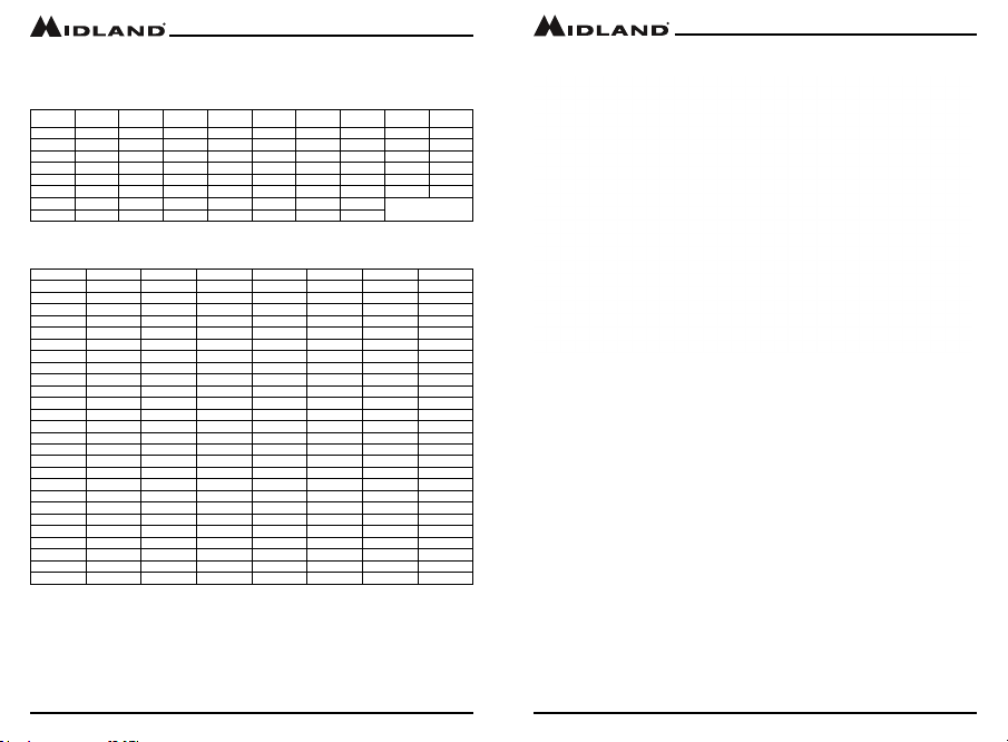
The MXT400 has 142 Privacy Codes (38 CTCSS codes and 104 DCS
codes), which can be applied to any channel. If desired, you can select
a dierent Privacy Code for each channel. See CTCSS Privacy Codes
Frequency Chart and DCS Privacy Codes Chart for lists of available
Privacy Codes.
IMPORTANT! To communicate between two MXT400 radios or any GMRS
radio, both radios must be set to the same channel (see Selecting the
Active Channel) and Privacy Code selections.
To select a CTCSS Privacy Tone:
1. Press the TS/DCS button once to enter the CTCSS Privacy Code
settings.
2. Use the Channel Knob to scroll forward or backward through the
CTCSS Tone options until the LCD displays the privacy tone frequency
desired.
3. Press the Select button to conrm your selection.
▪ The icon will show on the LCD display, according to your
selection.
4. Press the Scn/Mon button to exit Privacy Code settings.
midlandusa.com
Page 16
Page 17
midlandusa.com
Page 10
Model MXT400
Off ~ 9
Model MXT400
To select a DCS Privacy Code:
1. Press the TS/DCS button twice to enter the DCS Privacy Code settings.
2. Use the Channel Knob to scroll forward or backward through the DCS
Code options until the LCD displays the privacy code desired.
3. Press the Select button to conrm your selection.
▪ The DCS icon will show on the LCD display, according to your
selection.
4. Press the Scn/Mon button to exit Privacy Code settings.
NOTE: Pressing the TS/DCS button, three times while using CTCSS
tones and twice while using DCS codes, will disable the Privacy settings.
NOTE: If you select a CTCSS Privacy Code, any pre-selected DCS
Privacy Code will be cancelled, and vice-versa.
NOTE: If a DCS Privacy Tone is selected and you want to assign a
CTCSS tone you will be taken out of the privacy tone menu and forced to
start the selection process from the begining.
Selecting the Transmit (TX) Power Level
The MXT400 provides up to 3 transmit power levels; Hi, Mi and Lo. The Lo
power level is generally suitable when operating under optimum conditions
(see About Range). The Hi power level is recommended to ensure you
get maximum range from your radio.
To adjust the Transmit Power Level:
1. Press the Plvl button to toggle the transmit power setting between Hi,
Mi and Lo.
▪ Only the Mi and Lo transmit power settings will be indicated on the
LCD, when neither Mi or Lo is indicated the unit is set to Hi transmit
power.
▪ Due to output power regulations channels 1 through 7 cannot be
removed from the Lo transmit power setting.
midlandusa.com
Page 18
“MENU”MODE FUNCTIONS
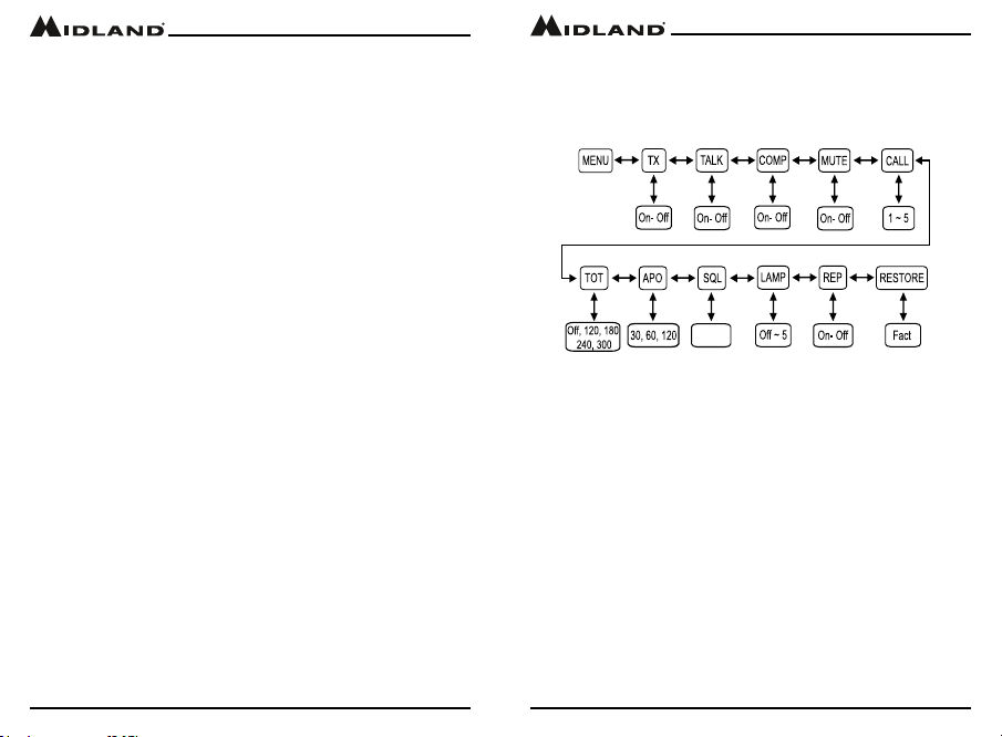
The “Menu” mode provides access to the features and functions shown in
the chart below. For additional utility functions, see UTILITY FUNCTIONS.
MXT400 “Menu” Mode Quick Reference Chart
Transmit (TX) Function
You can disable the transmitter section of the radio if you desire to use the
radio as a receive only system.
To set the Transmit Function
1. Press and hold the Menu button for 3 seconds to enter the Menu Mode.
2. Use the Call or Plvl buttons to scroll through the Menu options until the
LCD displays TX.
3. Turn the Channel knob to select the setting you desire.
4. Press and release the Select button to conrm your choice.
5. Press the Scn/Mon button to exit the Transmit Function
Talk Around (Talk) Function
The Talk Around function allows you to directly communicate with other
radios in your group when the repeater is not activated or out of range. The
radio will use the RX/TX frequency and it’s stored Privacy Tone settings.
when the Talk Around Function is enabled
Page 19
midlandusa.com
Page 11

Model MXT400
Model MXT400
To set the Talk Around Function
1. Press and hold the Menu button for 3 seconds to enter the Menu Mode.
2. Use the Call or Plvl buttons to scroll through the Menu options until the
LCD displays TALK.
3. Turn the Channel knob to select the setting you desire.
4. Press and release the Select button to conrm your choice.
5. Press the Scn/Mon button to exit the Talk Around Function.
Voice Compander (Comp) Function
The Voice Compander Function is used to reduce background noise and
enhance audio clarity, especially in long range communication.
To set the Compander Function
1. Press and hold the Menu button for 3 seconds to enter the Menu Mode.
2. Use the Call or Plvl buttons to scroll through the Menu options until the
LCD displays COMP.
3. Turn the Channel knob to select the setting you desire.
4. Press and release the Select button to conrm your choice.
5. Press the Scn/Mon button to exit the Compander Function.
Silent Operation (Mute) Function
The MXT400 has a Silent Operation mode. In this mode, all “beeps” and
“tones” are disabled.
To set the Silent Operation:
1. Press and hold the Menu button for 3 seconds to enter the Menu Mode.
2. Use the Call or Plvl buttons to scroll through the Menu options until the
LCD displays MUTE.
3. Turn the Channel knob to select the setting you desire.
4. Press and release the Select button to conrm your choice.
5. Press the Scn/Mon button to exit the Silent Operation Function.
Call Alert (Call) Function
The MXT400 can tranmsit dierent tones to other users alerting them to an
incoming message. The MXT400 has 5 selectable tones.
To set the Call Alert Tone
1. Press and hold the Menu button for 3 seconds to enter the Menu Mode.
2. Use the Call or Plvl buttons to scroll through the Menu options until the
LCD displays Call.
3. Turn the Channel knob to select the setting you desire.
4. Press and release the Select button to conrm your choice.
5. Press the Scn/Mon buttoon to exit the Call Alert Function
Time Out Timer (TOT) Function
The Time Out Timer limits the amount of transmittting time the radio has
per PTT activation.
To set the Time Out Timer
1. Press and hold the Menu button for 3 seconds to enter the Menu Mode.
2. Use the Call or Plvl buttons to scroll through the Menu options until the
LCD displays TOT.
3. Turn the Channel knob to select the setting you desire.
4. Press and release the Select button to conrm your choice.
5. Press the Scn/Mon button to exit the Time Out Timer Function.
Auto Power-O (APO) Function
The Auto Power-O function allows the user to set a time interval for the
radio to automatically power o after no use.
To set the Auto Power-O Function
1. Press and hold the Menu button for 3 seconds to enter the Menu Mode.
2. Use the Call or Plvl buttons to scroll through the Menu options until the
LCD displays APO.
3. Turn the Channel knob to select the setting you desire.
4. Press and release the Select button to conrm your choice.
5. Press the Mon/Scn button to exit the Auto Power-O Function.
midlandusa.com
Page 20
Page 21
midlandusa.com
Page 12

Model MXT400
Model MXT400
Squelch Sensitivity
The MXT400 has adjustable squelch sensitivity. The minimum squelch
level (OF) is the most sensitive, allowing the squelch to open on very weak
signals. Setting the squelch to the maximum setting (09) requires very
strong signals to open the squelch.
To adjust the Squelch Sensitivity:
1. Press and hold the Menu button for 3 seconds to enter the Menu Mode.
2. Use the Call or Plvl buttons to scroll through the Menu options until the
LCD displays SQL.
3. Turn the Channel knob to select the setting you desire.
4. Press and release the Select button to conrm your choice.
5. Press the Scn/Mon button to exit the Squelch Sensitivity Function.
Display Brightness
You can adjust the six brightness levels of the LCD display to ensure
optimum visibility under various daytime and night-time lighting conditions.
To adjust Display Brightness:
1. Press and hold the Menu button for 3 seconds to enter the Menu Mode.
2. Use the Call or Plvl buttons to scroll through the Menu options until the
LCD displays LAMP.
3. Turn the Channel knob to select the setting you desire.
4. Press and release the Select button to conrm your choice.
5. Press the Scn/Mon button to exit the Display Brightness
Function.
Repeater Channels
The MXT400 has the ability to talk to GMRS repeaters, which can greatly
increase radio range.
NOTE: Be sure to be aware of the local sharing and usage policies set
forth by the owner and operator of the repeater.
midlandusa.com
Page 22
To set Repeater Channel Function:
1. Press and hold the Menu button for 3 seconds to enter the Menu Mode.
2. Use the Call or Plvl buttons to scroll through the Menu options until the
LCD displays REP.
3. Turn the Channel knob to select the setting you desire.
4. Press and release the Select button to conrm your choice.
5. Press the Scn/Mon button to exit the Repeater Channel Function.
Restoring The Default Settings
You can restore the factory (default) settings for your MXT400 at any time.
To restore the Default Settings:
1. Press and hold the Menu button for 3 seconds to enter the Menu Mode.
2. Use the Call or Plvl buttons to scroll through the Menu options until the
LCD displays RESTORE.
3. Turn the Channel knob to select the FACT option.
4. Press and release the Select button to conrm your choice.
▪ Upon completion the radio will enter “standby” mode at channel 1,
with no Privacy Code selected.
CARE AND MAINTENANCE
CAUTION: DO NOT use alcohol or cleaning solutions to clean the radio.
DO NOT immerse the radio in water.
1. Use a soft cloth moistened with water to clean the radio.
2. Dry the radio with a dry lint-free cloth should it get wet.
Page 23
midlandusa.com
Page 13
Model MXT400
Model MXT400
TROUBLESHOOTING GUIDE
If you experience diculties using your MXT400, refer to the following
chart to correct common operation problems. If you have a problem which
you believe requires service, please call rst and speak with a service
technician at 816-241-8500. Many problems can be remedied over the
phone without returning the unit for service.
Problem Solution
No Power Check vehicle power source (battery); replace
Cannot Receive
Messages
Keypad is not
Responding
Backlight Display
is Dim
if needed.
Check input power connection and/or wires to
vehicle power source.
Check in-line fuse; replace if needed.
Verify both radios have the same Channel and
Privacy Code settings.
Make sure you are within range of the receiving
radio/repeater.
Conrm transmission is not aected by buildings
and other structures (see About Range)
If communicating with a repeater, verify if
repeater requires activation code.
Make sure keypad “lock” is not on (see Locking
the Keypad)
Reset the radio (turn radio o then back on)
Adjust the display illumination (see Display
Illumination)
SPECIFICATIONS
Channels:
Privacy Codes:
Operating Frequency:
Power Source:
15 GMRS Channels and
8 Repeater Channels
38 CTCSS; 104 DCS
UHF; 462.5500 ~ 462.725 MHz
UHF, 462.5625 ~ 467.725 MHz
13.8 VDC Nominal
midlandusa.com
Page 24
Page 25
midlandusa.com
Page 14
Model MXT400
CTCSS PRIVACY CODES FREQUENCY CHART (Hz)
Code Freq Code Freq Code Freq Code Freq Code Freq
1 67.0 9 91.5 17 118.8 25 156.7 33 210.7
2 71.9 10 94.8 18 123.0 26 162.2 34 218.1
3 74.4 11 97.4 19 127.3 27 167.9 35 225.7
4 77.0 12 100.0 20 131.8 28 173.8 36 233.6
5 79.7 13 103.5 21 136.5 29 179.9 37 241.8
6 82.5 14 107.2 22 141.3 30 186.2 38 250.3
7 85.4 15 110.9 23 146.2 31 192.4
8 88.5 16 114.8 24 151.4 32 203.5
DCS PRIVACY CODE CHART
No. CODE No. CODE No. CODE No. CODE
1 23 27 165 53 413 79 731
2 25 28 172 54 423 80 732
3 26 29 174 55 431 81 734
4 31 30 205 56 432 82 743
5 32 31 223 57 445 83 754
6 43 32 226 58 464 84 36
7 47 33 243 59 465 85 53
8 51 34 244 60 466 86 122
9 54 35 245 61 503 87 145
10 65 36 251 62 506 88 212
11 71 37 261 63 516 89 225
12 72 38 263 64 532 90 246
13 73 39 265 65 546 91 252
14 74 40 271 66 565 92 255
15 114 41 306 67 606 93 266
16 115 42 311 68 612 94 274
17 116 43 315 69 624 95 325
18 125 44 331 70 627 96 332
19 131 45 343 71 631 97 356
20 132 46 346 72 632 98 446
21 134 47 351 73 654 99 452
22 143 48 364 74 662 100 454
23 152 49 365 75 664 101 455
24 155 50 371 76 703 102 462
25 156 51 411 77 712 103 523
26 162 52 412 78 723 104 526
Model MXT400
midlandusa.com
Page 26
Page 27
2-Way Radios
2-Way Radios
Weather Radios
Emergency Crank Radios
HD Wearable Video Cameras
CB Radios
midlandusa.com
Page 15
Model MXT400
Model MXT400
ACCESSORIES
Accessories can be purchased at midlandusa.com
midlandusa.com
Page 28
FCC Warnings and Statements
IMPORTANT!
Changes or modications to this unit not expressly approved by
MIDLAND RADIO CORPORATION could void your right to operate this
unit. Your radio is set up to transmit a regulated signal on an assigned
frequency. It is against the law to alter or adjust the settings inside the
COMMUNICATOR to exceed those limitations. Any adjustment to your
radio must be made by qualied technicians.
This device complies with Part 15 of the FCC Rules. Operation
is subject to the following two conditions; (1) this device does not
cause any harmful interference, and (2) this radio must accept any
interference thay may cause undesired operations
Page 29
midlandusa.com
Page 16

Model MXT400
LIMITED WARRANTY (United States and Canada)
Subject to the exclusions set forth below, Midland Radio Corporation will repair or replace,
at its option without charge, any Midland FRS/GMRS which fails due to a defect in
material or workmanship within One Year following the initial consumer purchase.
This warranty does not apply to water damage, battery leak, abuse or misuse of
unauthorized accessories, unauthorized service or modication or altered products.
Accessories have a 90 day warranty from date of purchase, including the power cable
and microphone that are inbcluded with the unit.
ANY IMPLIED WARRANTIES, INCLUDING, WITHOUT LIMITATION THE IMPLIED
WARRANTIES OF MERCHANTABILITY AND FITNESS FOR A PARTICULAR
PURPOSE, SHALL BE LIMITED AS SET FORTH HEREIN AND TO THE DURATION
OF THE LIMITED WARRANTY, OTHERWISE THE REPAIR OR REPLACEMENT AS
PROVIDED UNDER THIS EXPRESS LIMITED WARRANTY IS THE EXCLUSIVE
REMEDY OF THE CONSUMER AND IS PROVIDED IN LIEU OF ALL OTHER
WARRANTIES, EXPRESS OR IMPLIED. IN NO EVENT SHALL MIDLAND BE
LIABLE, WHETHER IN CONTRACT OR TORT (INCLUDING BUT NOT LIMITED TO
NEGLIGENCE, GROSS NEGLIGENCE, BODILY INJURY, PROPERTY DAMAGE
AND DEATH) FOR DAMAGES IN EXCESS OF THE PURCHASE PRICE OF THE
PRODUCT OR ACCESSORY, OR FOR ANY INDIRECT, INCIDENTAL, SPECIAL OR
CONSEQUENTIAL DAMAGES OF ANY KIND, OR LOSS OF REVENUE OR PROFITS,
LOSS OF BUSINESS, LOSS OF INFORMATION OR DATA OR OTHER FINANCIAL
LOSS ARISING OUT OF OR IN CONNECTION WITH THE ABILITY OR INABILITY TO
USE THE PRODUCTS OR ACCESSORIES TO THE FULL EXTENT THESE DAMAGES
MAY BE DISCLAIMED BY LAW.
For Product Purchased in the USA:
Performance of any obligation under this warranty may be obtained
by returning the warranted product, prepaid freight, along with proof of
purchase to:
Midland Radio Corporation
Warranty Service Department
5900 Parretta Drive
Kansas City, MO 64120
This warranty gives you specic legal rights, and you may also have other
rights, which vary from state to state.
NOTE: The above warranty applies only to merchandise purchased in the United
States of America or any of the territories or possessions thereof, or from a U.S. Military
exchange.
For Product Purchased in Canada:
Performance of any obligation under this warranty may be obtained by returning the
warranted product, along with proof of purchase, to your place of purchase in Canada.
This warranty gives you specied legal rights. Additional warranty rights may be provided
by law in some areas within Canada.
midlandusa.com
Page 30
THIS PAGE IS
INTENTIONALLY
LEFT BLANK
Page 31
Model MXT400
midlandusa.com
Page 17

MIDLAND RADIO CORPORATION
5900 Parretta Drive
Kansas City, MO 64120
Call 816.241.8500
We’d love to hear from you! Let us know what
you think of your new Midland product at:
or by visiting us at:
midlandusa.com
Note: Features and Specications are subject to change without
notice. MIDLAND RADIO CORPORATION is not responsible for
unintentional errors or omissions on its packaging.
 Loading...