

Page 1
User Manual
GEOPOINT BOX
PERSONAL TRACKER
User Manual
Page 2
GEOPOINT BOX
PERSONAL TRACKER
User Manual
July Edition 2009
Page 3

Limitation of Liability
The Manufacturer reserves the right to modify the devices or the device specifi cations in this manual without prior notice. Any copy of this manual,
in part or in full, whether by photocopy or by other means, even of electronic nature, without the manufacture giving written authorisation, breaches
the terms of copyright and is liable to prosecution.
It is absolutely forbidden to use the device for different uses other than those for which it has been devised for, as inferred to in this manual. When
using the features in this device, obey all laws and respect privacy and legitimate rights of others.
EXCEPT TO THE EXTENT PROHIBITED BY APPLICABLE LAW, UNDER NO CIRCUMSTANCES SHALL THE MANUFACTURER BE LIABLE FOR
CONSEQUENTIAL DAMAGES SUSTAINED IN CONNECTION WITH SAID PRODUCT AND THE MANUFACTURER NEITHER ASSUMES NOR
AUTHORIZES ANY REPRESENTATIVE OR OTHER PERSON TO ASSUME FOR IT ANY OBLIGATION OR LIABILITY OTHER THAN SUCH AS IS
EXPRESSLY SET FORTH HEREIN.
All trademarks in this manual are property of their respective owners.
Java is a registered trademark of Sun Microsystems, Inc.
The information contained in this manual is for information purposes only, is subject to changes without previous notice and cannot be considered
binding for the Manufacturer. The Manufacturer assumes no responsibility for any errors or incoherence possibly contained in this manual.
Printed in Italy.
Note for the users of appliances
According to the article 13 of the Legislative Decree no. 151 dated July 25, 2005, “Enforcement of the 2002/95/EC and
2003/108/EC directives, relavant to the reduction of dangerous substances in electric and electronic applinaces, as well
as waste disposal”, the symbol of a crossed dustbin applied on appliances or on their cases means that the product at
the end of its life cycle must be disposed in a dedicated location than other waste.
The user must, therefore, dispose the aplliance at its end-of-life in the relevant disposal site for electric and electronic waste or
give it back to resellers at the time of purchasing a news equivalent one.
The correct disposal and consequant start up of a recycling of the unused appliance, treatment and fi nal disposal compatible
to the enviroment concurs to avoid possible negative effects on the enviroment and health and favours the reusing and / or
recycling of the parts making the apparatus.
The abusive disposal of such products done by users is fi ned according to the present legislation.
Page 4

Contents
Safety Instructions
.................................................................................................................
5
General Information
............................................................................................................
10
Preliminary Procedures
.......................................................................................................
18
Safety Instructions
Environment ................................................................................................................... 7
Medical Appliances ....................................................................................................... 7
Vehicles .......................................................................................................................... 8
Potentially Explosive Environments ............................................................................... 9
General Information
Information on the Tracker ........................................................................................... 10
Package Contents ....................................................................................................... 14
Network Services ......................................................................................................... 15
Preliminary Procedures
Inserting the SIM Card and Battery ............................................................................. 18
How to Charge the Battery .......................................................................................... 21
Battery Life ...................................................................................................................22
Information on the Battery ........................................................................................... 23
Power On and Off ........................................................................................................ 24
LED Indicators ............................................................................................................. 24
.................................................................................................................
ECYCLING THE PRODUCT AND ITS RELEVANT ACCESSORIES ................................................. 7
R
P
ACEMAKER ................................................................................................................ 8
HEARING AIDS ............................................................................................................ 8
............................................................................................................
O
PTIONAL ACCESSORIES ............................................................................................. 14
GSM / GPRS N
GPS SYSTEM ........................................................................................................... 16
ETWORK ........................................................................................... 15
.......................................................................................................
Page 5

Use of the Functions
Use of the Functions
...........................................................................................................
26
Reading and Writing SMS Commands
...............................................................................
39
Troubleshooting
...................................................................................................................
46
Maintenance
.......................................................................................................................
48
Manufacturer’s Limited Warranty
.........................................................................................
49
SOS Key ....................................................................................................................... 27
Position Request .......................................................................................................... 28
Automatic Position Sending ......................................................................................... 29
Position Data and Events Recording ........................................................................... 30
Geofence ..................................................................................................................... 32
Anchor .........................................................................................................................33
Power Save Mode ........................................................................................................ 35
Alarm SMS ................................................................................................................... 37
Reading and Writing SMS Commands
Troubleshooting
Maintenance
Manufacturer’s Limited Warranty
Warranty Period ........................................................................................................... 49
How to get Warranty Service ....................................................................................... 50
What the Warranty does not Cover .............................................................................. 50
Other Important Notices .............................................................................................. 52
Limitation of the Manufacturer’s Liability ...................................................................... 53
...........................................................................................................
...............................................................................
...................................................................................................................
.......................................................................................................................
.........................................................................................
Page 6

Safety Instructions
Safety Instructions
Please read the following safety instructions carefully. Not following them may be dangerous and/or illegal.
Please read carefully the user manual for further details.
SWITCHING ON IN SAFE ENVIRONMENTS
Do not switch the device on when prohibited or whenever it could cause any interference or
Obey all local laws. Always keep your hands free to operate the vehicle while driving. Your fi rst
All wireless devices may be susceptible to interference, which could affect the performance of
Follow any restrictions. Switch the device off in hospitals or near medical equipment (hearing aid
Follow any restrictions. Wireless and digital devices can cause interference with aircraft
Do not use the device at a refuelling point. Switch-off when near petrol stations or fuel depots
danger.
ROAD SAFETY
consideration while driving should be road safety.
INTERFERENCE
other appliances (TV, radio,...)
SWITCH OFF IN HOSPITALS
equipment, pacemaker, ...) the device could cause interference. Always keep a distance of 20
cm between pacemaker and device.
SWITCH OFF IN AIRCRAFT
equipment.
SWITCH OFF WHEN REFUELLING
and chemical plants. The device could interfere with the correct functioning of the electronic
equipment.
5
Page 7

Safety Instructions
SWITCH OFF NEAR BLASTING
Follow any restrictions. Do not use the device where blasting is in progress.
USE THE DEVICE SENSIBLY
Do not use the device for any uses other than those it has been built for. Keep to the instructions
Only qualifi ed personnel may install or repair this product.
Use only approved accessories and batteries. Do not use incompatible products. The use of
The batteries must be disposed according to the appropriate modes. The consumer must duly
The device is not water-resistant, keep it dry. Contact with water or any other liquid could cause
Please handle the tracker and its relevant accessories with care. Read the following instructions carefully.
as explained in the product manual.
QUALIFIED SERVICE
ACCESSORIES AND BATTERIES
nonstandard products can cause damage to device and/or people.
BATTERY DISPOSAL
hand in worn out batteries, either at the appropriate collection points for the general public, in
his own town, or wherever batteries of the same kind are sold (compulsory warning according to
law on the disposal of batteries).
AVOID GETTING THE DEVICE WET
serious damage to the device.
6
Page 8

Safety Instructions
Environment
Always switch off the device in areas where it is prohibited, or whenever it could cause interference or danger.
Always observe the specifi c local rules and standards. Use the device in its normal operating position only.
The device complies with the laws for exposure to radio-frequencies when used in the normal position or when
positioned at least 2.2 cm (7/8 inches) away from the body. In the event that a device holder, a belt clip or
some other kind of support, is used, it is necessary that such object does not contain metallic parts and that
it is positioned from the body at a previously gauged distance. Some parts of the device are magnetic. Pay
attention with nearing credit cards or other magnetic memorization supports: the saved information could be
erased.
Recycling the Product and its Relevant Accessories
Do not recycle the device or its electronic accessories, like battery chargers, with household waste. Some
countries provide recycling systems. For further information, please contact the local authorities.
Medical Appliances
Always switch off the device whenever in hospitals and in health care structures. Any medical appliances
could be sensitive to radio-frequency signals. Consult a doctor or the manufacturer of the medical appliances
to fi nd out if an they are adequately shielded from radio-frequency signals and to get more details.
7
Page 9

Safety Instructions
Pacemaker
A minimum distance of 15.3 cm (6 inches) between the device and a pacemaker is recommended in order to
avoid interference with the medical appliance.
In the event of pacemaker wearers, please observe the following precautions:
always keep the device more than 15.3 cm (6 inches) away from the pacemaker•
never keep the device in close contact with the body (e.g. in a pocket) •
always keep the device against the ear on the opposite side of the pacemaker•
In the event of suspected interference with the pacemaker, switch off and remove the device immediately.
Hearing Aids
The device could interfere with certain hearing aids. If this should occur, please contact your retailer.
Vehicles
Electronic systems which have been incorrectly installed or inadequately shielded in motor vehicles (e.g.
electronic fuel injection systems, electronic anti-skid braking systems, electronic speed control systems, air
bag systems) can be affected by the interference from radio frequency signals. For further information, refer
to the vehicle manufacturer. Only qualifi ed personnel should service the device, or install the device in a
vehicle.
Faulty installation or service may be dangerous and may invalidate any warranty that may apply to the device.
Do not place objects, including installed or portable wireless equipment, in the area over the air bag or in the
air bag deployment area. If the air bag infl ates, people could be seriously injured.
Using your device while fl ying in an aircraft is prohibited. Switch off your device before boarding the aircraft.
8
Page 10

Safety Instructions
Potentially Explosive Environments
Switch off your device in any area with a potentially explosive atmosphere, (e.g. where you would be normally
advised to turn-off your vehicle engine) and obey all signs and instructions in that area. Switch off the device
near refuelling points and at service stations.
9
Page 11

General Information
General Information
This chapter contains general information on the tracker and its relevant accessories.
WARNING: The GPS receiver and the GSM device work at higher radio frequencies which can
be stopped by enclosures containing metal and plastic parts. It is suggested to keep the tracker
under light clothes, as external as possible.
Examples of shielding materials: kevlar, carbon fi bre, some polyurethanic and polyamidic resins
especially if black, etc.
Examples of materials which cannot infl uence the radio waves: ABS, ABS+PC, policarbonate,
etc.
Information on the Tracker
This tracker is approved for use on the EGSM 850/900/1800/1900 MHz network. For further information relevant
to the networks, please ask your network service provider.
WARNING: During tracker use, all laws must be obeyed, including the privacy and legitimate
rights of the others.
WARNING: To use all the tracker functions, except for Power Save Mode, the tracker must be
kept switched on.
WARNING: When the tracker is connected to USB port, it is not possible to receive or send
SMS messages.
10
Page 12

General Information
The tracker is a portable device able to transmit its geographical location to a mobile phone or PC in real-time.
Moreover, the detected data can be recorded for further analysis.
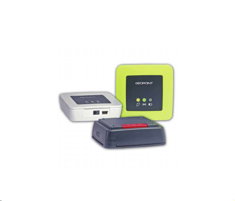
The tracker is available in two different version:
LCD• : GPS tracker with display, phone and 2MB data memory.
BOX• : GPS tracker without display, without vocal communication and 512kB data memory.
Both trackers can be offered combined in the KIT version, particularly indicated for the use of Finder function,
useful for real-time locating.
This User Manual describes the tracker in the BOX version.
Thanks to the latest generation SiRFstarIII GPS receiver, the tracker can locate the exact coordinates of its
position and send the data to:
a mobile phone, by means of an SMS message•
a PC, by means of an analog/GSM modem•
This data (latitude, longitude, altitude, information on speed, date and time) can be sent:
at a continuously programmed rate •
when the tracker leaves a pre-established area •
in case of an emergency, by means of an SOS message•
The tracker have 512 kB of non-volatile memory. The saved data (location coordinates, events, ...) can be
transferred to a PC and analysed by means of the provided software.
The tracker can be updated or have more functions added to it by means of an USB cable connected to a PC
at any given time (refer to the user manual of the provided software).
The tracker has two basic functions:
locating and transmitting its actual position•
sending an SOS message in case of an emergency•
11
Page 13

General Information
The tracker can be used as a system for:
l• ocating elderly people, children, or anyone in diffi culty, or with health problems or cognitive disorders,
etc.
locating, during outdoor individual sports activities (e.g. mountaineering, trekking, parachuting,...)•
locating and fi nding lost pets•
locating groups of people (e.g. park guards, local police forces, emergency teams,...)•
locating small boats•
GPS anti-theft system for vehicles, motorcycles, goods,...•
route recording•
Front view
Features:
ON/OFF button•
BUZZER for acoustic warning•
yellow LED for GPS signal status•
green LED for GSM network status•
red LED for battery status•
Side and back view
Features:
SOS key•
connector for USB cable•
power supply connector (DC IN)•
12
Page 14
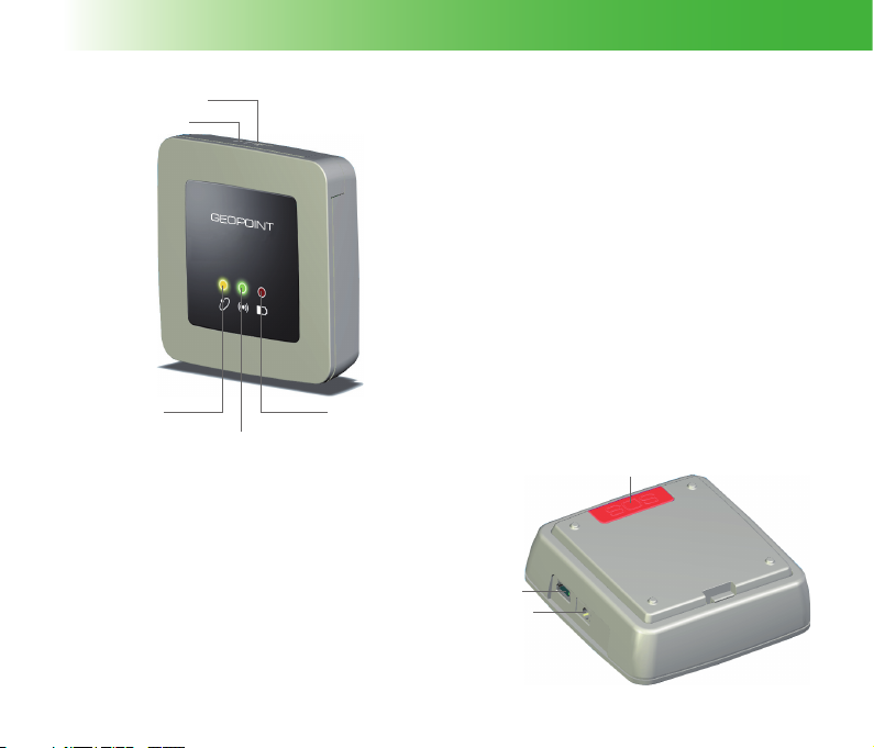
ON/OFF
BUZZER
General Information
YELLOW LED
(GPS)
GREEN LED
(GSM)
RED LED
(BATTERY)
SOS KEY
USB
DC IN
13
Page 15

General Information
Package Contents
Available accessories:
No. 1 USB cable•
No. 1 (2 in case of KIT) European battery charger - • American battery charger available on request
No. 1 (2 in case of KIT) Li-ion battery•
No. 1 CD ROM for MyTrack software installation, for tracker management and personal tracking•
No. 1 (2 in case of KIT) User Guide of the tracker•
Use only accessories, batteries and battery chargers approved by the Manufacturer. The manufacturing
company is not liable for any damage to the tracker due to the use of accessories different from those
expressly indicated.
WARNING: When disconnecting any cable from the tracker, fi rmly hold and pull on the plug,
not on the cable.
Optional Accessories
The optional and/or additional accessories, available on request, are:
Car charger•
Li-ion battery•
Map software•
14
Page 16

General Information
Network Services
In order to use some tracker functions, such as sending and/or receiving SMS messages, data communication,
GPRS, etc., it is necessary to get access through the network service provider.
GSM / GPRS Network
The GSM network (Global System for Mobile Communications) is a data transmission system available from
the network service provider. For further information about availability, services and relevant costs of SIM
cards, please contact the network provider.
The GPRS network (General Packet Radio Services) is a high speed data transmission system. If available,
this system allows the continuous connection to the network. The supply mode of the GPRS services can
change according to the network provider.
In the event that the network service coverage is missing, some tracker functions may not be available.
After having carried out all settings, the GPRS communication can be enabled:
automatically, if the rate for cyclic GPRS connection has been set.•
manually, sending the proper SMS command to the tracker by means of a GSM device (e.g. a mobile •
phone). The tracker will send a reply message and start GPRS connection with the provided software.
For the manual connection, the provided software can accept the connection automatically if the Autoanswer
function was enabled, if not, the provided software will display a confi rmation message to open the
communication channel.
For the automatic cyclic connection, the provided software will accept and close automatically the
connection.
15
Page 17
General Information
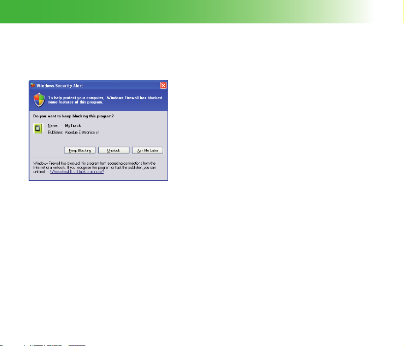
To communicate with the tracker through a PC in GPRS network, check if a fi rewall is installed, and allow the
access to the port which will be used for the communication. This procedure must be carried out only by
people which have the proper technical features.
If Windows Firewall is enabled, during the communication GPRS access the following window is displayed.
Keep Blocking The access to the port is stopped. It is
Unblock The access to the port is always allowed.
Ask Me Later The access to the port is temporary
If external fi rewall is installed, refer to the network administrator.
GPS System
The GPS (Global Positioning System) is able to detect the user’s position in any given point of the Earth’s
surface and consists in a ground receiver which captures signals from a series of satellites in orbit.
The GPS receiver analyses and calculates the data received from the satellites and pin-points the present
location (FIX procedure).
If the GPS receiver reports that a two dimensional satellite FIX is available (2D FIX), it means that the signal
is adequate.
not allowed to communicate in GPRS
network.
It is possible to communicate in GPRS
network.
allowed. It is possible to communicate in
GPRS network. At the next communication
GPRS access, the same window will be
displayed.
16
Page 18

General Information
If the GPS receiver reports that a three dimensional satellite FIX is available (3D FIX), it means that the signal
is optimal.
In some climatic or structural conditions, (when it is foggy, clouded, ... or inside buildings, tunnels, ...) partial
or total GPS signal coverage may be missing. In this case, some functions may not be available.
Notwidstanding the Selective Availability (SA) introduced by United States of America for military reasons, the
margin of error on the GPS data is only limited but not deleted. The location data can contain inaccuracies
caused by external factors as errors in the orbit and in the satellites clock, climatic conditions and multipath
effects.
17
Page 19

Preliminary Procedures
Preliminary Procedures
This chapter contains all the information on the preliminary procedures relevant to the tracker use.
Inserting the SIM Card and Battery
The SIM card allows to receive and transmit data and calls by means of the GSM network. Pay attention when
choosing the contract type to make with the SIM card provider, since it could affect the tracker communication
functions. For example, in case of:
a prepaid SIM card, communication between the tracker and the provided software is made exclusively •
through SMS text or GPRS network.
a SIM card with subscription, communication between the tracker and the provided software is made •
through SMS text, GPRS network or also sending/receiving data (only if the data number has been
activated by the network provider).
The SIM card is not included in the package. To buy one, please contact the network service provider or
specialized retailer.
WARNING: For a proper tracker operation, in case of prepaid SIM card, make sure that the
account is not exhausted.
WARNING: If the battery is not inserted within 30 seconds, the date and time settings will be
erased.
WARNING: Before inserting the SIM card, check if it is protected by a PIN code. If the PIN code
has been activated, disable it by means of a mobile phone.
WARNING: Inserting a SIM card, any SMS message contained in it will be deleted. Therefore,
it is advisable to carry out a data back-up before SIM card insertion.
18
Page 20

Preliminary Procedures
WARNING: After SIM card insertion, any SMS message which will be received, it will be
erased.
WARNING: Before proceeding with any insertion/removal of the SIM card, switch off the tracker,
disconnect the battery charger and/or the USB cable.
To insert/remove the SIM card or the battery, proceed as follows.
Remove the back cover from the tracker by pressing down on the small fl ap 1.
and lifting upwards (Pict. 1).
Remove the battery by lifting it out (Pict. 2).2.
Pict. 1
Pict. 2
19
Page 21

Preliminary Procedures
Insert the SIM card by leading it into the appropriate housing; check 3.
if it has been inserted correctly, with the golden contact area facing
downwards (Pict. 3).
Insert the battery paying attention to coincide the contact area with that of 4.
the tracker. Close the tracker by replacing the back cover (Pict. 4).
WARNING: Insertion/removal of the SIM card must be carried out with extreme care, to avoid
damaging the tracker, battery or SIM card.
Pict. 3
Pict. 4
20
Page 22

Preliminary Procedures
How to Charge the Battery
Before using the tracker for the fi rst time, the battery must be completely charged.
Before charging, check that the network electrical supply corresponds to that of the battery charger. Do not
exceed the network voltage indicated on the battery charger.
To charge the battery:
Plug the provided battery charger into the electrical supply socket.1.
Connect the battery charger cable to the appropriate tracker 2.
connector.
The tracker red LED will switch on and it will be on for all the battery 3.
charging process.
WARNING: Use only batteries and battery chargers with the following features:
Battery: model ABL-6C Li-ion - 3,7V 1000mAh•
Battery charger: model ZD050050EU•
Car charger: model ESC-004•
input 13,6VDC
output 5VDC 500mA
The manufacturing company is not liable for any damage to the tracker due to the use of
accessories different from those expressly indicated.
WARNING: Do not leave the tracker in particularly hot or cold environments during the battery
charging. Keep the tracker between -10°C and +40°C environmental temperature.
WARNING: To disconnect the battery charger cable from the tracker, fi rmly hold and pull on the
plug, not on the cable.
input 100VAC - 240V 50/60Hz 0,15A
output 5VDC 500mA
21
Page 23

Preliminary Procedures
Battery Life
The tracker battery life changes according to the environment conditions and its activity. The following table
shows the battery life in several conditions.
STATUS TIME
Standby mode with motion sensor active. ~10 days
Tracking SMS every minute (GPS always on). ~9 hours
Tracking SMS every 5 minutes (GPS with hotstart). ~4 days
Continuous tracking. ~2 hours
Data connection mode, with GPS system continuously active. ~2 hours
Position data recording every minute. ~37 hours
Tracker not in use. ~2 days
Tracker in communication on GSM network. ~4 hours
The data in the table refers to the new battery provided with the tracker, when totally charged. This data is
an indication and could be highly infl uenced both by the GSM signal, because it affects the time required for
network connection, and GPS signal, because it affects the time required for position fi xing.
NOTE: When the battery is almost discharged, the tracker emits an acoustic warning every
minute. When the battery is completely discharged, the tracker automatically switches off.
NOTE: If the battery discharges, no acoustic warning is emitted and the programmed functions
(e.g. the tracking SMS sending) will not be available.
22
Page 24

Preliminary Procedures
Information on the Battery
A new battery reaches maximum performance only after being completely charged and discharged 2 or 3
times. The battery can be charged and discharged several times, but will eventually wear out with use.
A completely charged battery can discharge itself even when left unused. When the tracker loses the
performance quality, it is necessary to replace the battery.
Always disconnect the battery charger and the tracker from the electrical supply when not charging. Do not
charge the battery in housings other than that of the tracker.
Never shortcircuit the battery. This could even happen accidentally, if a battery comes into contact with a
metallic object (coins, pens, paperclips,...) damaging the battery or the object.
The battery life could be noticeably reduced if subjected to extreme temperatures (too cold or too hot). Keep
the battery at room temperature between 15°C and 25°C (59°F and 77°F).
Pay attention to damaged batteries. Do not throw batteries in the fi re: they could explode. Recycle the batteries
according to the local laws. It is absolutely forbidden to throw batteries away with household refuse.
WARNING: Use the batteries only for their intended purpose. Use only the battery and the
provided battery charger.
23
Page 25

Preliminary Procedures
Power On and Off
To switch the tracker on/off, press the key situated in the upper part of the device
for 2 seconds. At tracker switching on/off, the 3 LEDs will light up together at the same
time for 1 second and an acoustic signal will be emitted.
WARNING: Do not switch on the tracker when its use is prohibited or
when it may cause interference or danger (refer to the chapter Safety
Instructions).
NOTE: The GPS receiver is switched on automatically only if the
programmed tracker functions require the GPS system use.
LED Indicators
The LED indicators on the device front part shows the tracker main functions status.
24
ON / OFF
Page 26

Preliminary Procedures
LED indicators
Yellow LED - GPS signal status
OFF • T tracker off or GPS receiver switched off
ON • T waiting GPS
blinks every second • T poor signal level (2D FIX)
blinks every 4 seconds • T high signal level (3D FIX)
Green LED - GSM network status
OFF • T tracker off or connected to the USB port
blinks every second • T network search in progress
blinks every 4 seconds • T suffi cient signal strength
2 blinks every 4 seconds • T GSM/GPRS data communication in progress
Red LED - battery status
OFF • T tracker off or battery completely charged
blinks every 2-3 seconds • T battery discharged
ON • T battery charging in progress
NOTE: The 3 LEDs remain continuously ON during tracker fi rmware update.
Identifi cation symbols
25
Page 27

Use of the Functions
Use of the Functions
Tracker Function Description Refer to
SOS key
Position Request
Automatic Position Sending
Position Data Recording
Geofence
Anchor
Power Save Mode
Alarm SMS
the tracker sends an alarm message section SOS Key
the tracker sends an SMS containing
its position to the phone number which
requested this data
the tracker sends automatically its position
by SMS or by GPRS connection
the tracker records its position data to
review the track afterwords
the tracker sends an alarm SMS to the
preset phone number everytime it exits or
ri-enters in a preset rectangular area
the tracker sends an alarm SMS to the
preset phone number everytime it exits or
ri-enters in a preset circular area
the tracker switches on/off automatically to
optimize the battery consumption
the tracker sends alarm SMS to the preset
phone number everytime a status change
happens (low battery, memory full, ...)
section Position Request
section Automatic Position Sending
section Position Data and Events Recording
section Geofence
section Anchor
section Power Save Mode
section Alarm SMS
26
Page 28

Use of the Functions
The tracker can work without the SIM card. In this case, all functions operating with GSM/GPRS network will
not be available.
If no SIM card has been inserted, only the following functions are available:
Position data recording•
Power save mode with motion sensor•
Furthermore, only by the provided software it is possible to:
disable all the acustic signals of the tracker (Silent mode)•
select the language for the SMS messages sent by the tracker•
SOS Key
By pressing the SOS key for at least 2 seconds, for 5 consecutive times every minute, an SMS message is
immediately sent to the preset phone numbers (max. 4 phone numbers). This message contains the current data
on the location, if the GPS signal has been revealed. If there is no GPS signal coverage, the last position data will
be sent. The red SOS key can be found on the back of the tracker and is used for alarm purposes only.
Programming
To use this function, it is necessary to set the phone numbers (max. 4 phone numbers) where the SOS
messages will be sent.
1) Set the phone numbers Using the provided software
SOS SENDING
Every time the SOS key is pressed, an acoustic warning signal is emitted when:
there is no GSM signal•
no SMS center number or no SOS numbers have been set•
the set SMS center number is not correct•
27
Page 29

Use of the Functions
NOTE: When there is no GSM signal, the alarm functions may not be available.
Example of the SMS message displayed on the mobile phone, with the detected current position data
GEO,ID:GLORIA,SOS ALARM,POS:45g37.9480N,008g28.9992E,ALT:0218m,07/04/10,10:09
Example of the SMS message displayed on the mobile phone, with the last position data detected
before the GPS signal loss
GEO,ID:GLORIA,SOS ALARM,LAST POS:45g37.9480N,008g28.9992E,ALT:0218m,07/04/10,10:09
The SMS message structure of the SOS function is described here below:
GEO Tracker type.
ID:−−−−−− Tracker name preset by the user through the provided software.
SOS ALARM Alarm message.
POS:−−−−−.−−−−−,−−−−−.−−−−− Latitude and longitude of the geographical position.
ALT:−−−−.− Altitude in m.
−−/−−/−−,−−:−− Event date and time (yy/mm/dd hh:mm).
Position Request
It is possible to ask for the tracker position by means of an SMS command. After receiving the SMS command,
the tracker sends a message containing its position data to the phone number which sent the command.
To know the tracker position in real time, send the following SMS command:
After the tracker receives the SMS command, it sends an SMS containing the position data.
rpos
28
Page 30

Use of the Functions
Programming
To use this function, it is necessary to send to the tracker an SMS command by a mobile phone or by a GSM
device and waiting for the reply.
1) Tracker position request in realtime Sending an SMS command (rpos)
Automatic Position Sending
The tracker can send its own position at a programmable rate. The automatic position sending can be carried
out in two different modes:
by SMS•
by GPRS connection•
CYCLIC POSITION SMS
The tracker can send an SMS message at intervals, containing all the information on its current position. This
function is useful for monitoring the tracker motion at a distance by a mobile phone.
Programming
To use this function, it is necessary to set the phone number where the position messages will be sent, set
the rate for cyclic position SMS and then enable the function.
1) Set the phone number Using the provided software
2) Set the rate for cyclic position SMS Sending an SMS command (wposc)
Using the provided software
3) Enable the cyclic position SMS Sending an SMS command (wposc)
Using the provided software
29
Page 31

Use of the Functions
CYCLIC GPRS CONNECTION
The cyclic GPRS connection allows to connect the tracker automatically at a programmed rate for the
continuous position updating. At the programmed rate, the tracker will be connected only for the time needed
for sending the position point. This function is very useful if combined with the I-Scout web server as it allows
to display the detected positions by every station connected to internet.
Programming
To use this function, it is necessary to set the GPRS communication parameters, and then enable the
function setting the rate for cyclic GPRS connection.
1) Set the GPRS parameters
Using the provided software
2) Enable the cyclic GPRS connection setting the rate Using the provided software
Sending an SMS command (wgprs)
Position Data and Events Recording
The tracker allows to record:
the detected events automatically without setting the recording•
the position data to review the track afterwords, if the recording was previously set•
The tracker can records approx. 14,800 position points and approx. 1,900 events.
When an event occurs, the tracker detects it and start to record in the Event LOG.
30
Page 32

Use of the Functions
The following list shows all the events which can be detected and recorded automatically by the tracker.
power on/off•
low battery•
receiving a data call•
making a GPRS call•
hanging up a call•
motion on/off•
GSM network available/unavailable•
GPS signal available/unavailable•
entry/exit from Geofence area•
entry/exit from Anchor area•
fi rmware update•
SOS alarm•
memory erasing•
roaming on/off•
network GSM provider changing if roaming on•
Programming
To record position data, it is necessary to set the recording parameters.
1) Set the recording parameters Using the provided software
WARNING: If the Power Save Mode with cyclic position SMS or cyclic GPRS connection has
been enabled, the tracker position will be recorded at each automatic switching ON. The set
Rate and Distance parameters will not be considered.
31
Page 33

Use of the Functions
All position data contained in the tracker memory can be erased.
1) Erase the recorded position data Sending an SMS command (wem)
Using the provided software
WARNING: The Erase function deletes all GPS data contained in the tracker memory. Once
deleted, the data is no longer retrievable.
Geofence
The Geofence function allows to monitor the tracker entry and exit in a pre-established area.
This is a rectangular area and can be programmed setting the area diagonal coordinates.
Programming
To use this function, it is necessary to set the phone number where the alarm messages will be sent, and
then set the two points which defi ned the area diagonal.
1) Set the phone number Using the provided software
2) Set the two points which defi ned the area diagonal Sending an SMS command (wgf)
Using the provided software
After having set the Geofence parameters, the tracker will send an alarm SMS message to the preset phone
number each time it enters/exits the pre-established area or each time it is switched on outside the preestablished area.
Example of SMS message displayed on the mobile phone, when the tracker enters the area
GEO,ID:GLORIA,GEOFENCE ENTER,POS:45g37.9481N,008g28.9992E,ALT:0218m,07/04/10,10:09
32
Page 34

Use of the Functions
Example of the SMS message displayed on the mobile phone, when the tracker exits the area
GEO,ID:GLORIA,GEOFENCE EXIT,POS:45g37.9481N,008g28.9992E,ALT:0218m,07/04/10,10:09
The SMS message structure of the Geofence function is described here below:
GEO Tracker type.
ID:−−−−−− Tracker name preset by the user through the provided software.
GEOFENCE ENTER Alarm message.
POS:−−−−−.−−−−−,−−−−−.−−−−− Latitude and longitude of the geographical position.
ALT:−−−−.− Altitude in m.
−−/−−/−−,−−:−− Event date and time (yy/mm/dd hh:mm).
Anchor
The Anchor function allows to monitor within a pre-established circular area the position of a person, an object
or an animal. When the tracker detects the exiting from the pre-established area or the ri-entering, it sends an
alarm SMS containing its position data to the preset phone number.
This function is programmable using the complete SMS command (enabling and radius setting) or partially
by the provided software.
When the complete SMS command is received by the tracker (e.g. wanc=1,0500), the function is enabled and
the current tracker position is considered as area central point. If the function is enabled without setting the
radius, the previously set coordinates for the central point and the last programmed radius will be considered.
If no radius was previously programmed, by default it will be set to 100 m.
33
Page 35

Use of the Functions
Programming
To use this function, it is necessary to set the phone number where the alarm messages will be sent, defi ned
the circle centre and then set the radius.
1) Set the phone number Using the provided software
2) Defi ne the circle centre Sending the complete SMS command (wanc)
3) Set the radius value Sending an SMS command (wanc)
Using the provided software
After having carried out the entire programming procedure, the tracker must be fi tted to the person or animal
to be monitored. When the tracker detects the exiting from the pre-established area or the ri-entering, it sends
an alarm SMS containing its position data to the preset phone number.
Example of the SMS message displayed on the mobile phone, when the tracker enters the area
GEO,ID:GLORIA,ANCHOR ENTER,POS:45g37.9481N,008g28.9992E,ALT:0218m,07/04/10,10:09
Example of the SMS message displayed on the mobile phone, when the tracker exits the area
GEO,ID:GLORIA,ANCHOR EXIT,POS:45g37.9481N,008g28.9992E,ALT:0218m,07/04/10,10:09
The SMS message structure of the Anchor function is described here below:
GEO Tracker type.
ID:−−−−−− Tracker name preset by the user through the provided software.
ANCHOR ENTER Alarm message.
POS:−−−−−.−−−−−,−−−−−.−−−−− Latitude and longitude of the geographical position.
ALT:−−−−.− Altitude in m.
−−/−−/−−,−−:−− Event date and time (yy/mm/dd hh:mm).
34
Page 36

Use of the Functions
Power Save Mode
The Power Save Mode allows for optimal management of the tracker battery. It is possible to set the tracker
automatic switching on/off according to specifi c use requirements.
NOTE: It is not possible to enable more than one Power save mode simultaneously.
NOTE: When the tracker is switched off in Power save mode, an SOS message can be sent
pressing the relevant red key for at least 2 seconds.
The fi rst mode allows the automatic tracker switching on at motion detection. When no motion is detected for
a preset time and there is no data exchange, the tracker will automatically switch off.
The second mode allows the automatic tracker switching on at the cyclic position SMS sending. Before using
this mode, enable and set the Cyclic position SMS function with SMS rate 5 minutes. The tracker will switch
off automatically after position SMS sending and after carrying out all the preset operations.
During the automatic switching on, if the tracker is connected by the provided software, the automatic
switching off will be carried out after position SMS sending, after carrying out all the preset operations and 2
minutes after tracker disconnection.
The third mode allows the automatic tracker switching on at the cyclic GPRS connection with the provided
software or with the I-Scout web server. Before using this mode, enable and set the Cyclic GPRS connection
function with rate 5 minutes. The tracker will switch off automatically after carrying out all the preset
operations. If the GPRS connection fails twice, the tracker will switch off automatically.
35
Page 37

Use of the Functions
Programming
To use this function, it is necessary to set the parameters relevant to one power save mode.
1. MOTION MODE
1) Set the motion sensor parameters (sensitivity, timeout) Using the provided software
2) Enable the power save mode with motion sensor Using the provided software
2. CYCLIC POSITION SMS MODE
1) Enable the cyclic position SMS Sending an SMS command (wposc)
Using the provided software
2) Set the phone number Using the provided software
3) Set the rate for cyclic position SMS 5 minutes Sending an SMS command (wposc)
Using the provided software
4) Enable the power save mode with cyclic position SMS Sending an SMS command (wposc)
Using the provided software
3. CYCLIC GPRS CONNECTION MODE
1) Set the GPRS parameters Using the provided software
2) Set the rate for cyclic GPRS connection 5 minutes Using the provided software
3) Enable the power save mode with cyclic GPRS connection Using the provided software
36
Page 38

Use of the Functions
Alarm SMS
The Alarm SMS are alarm messages sent (if the function was enabled) to a phone number every time that:
the tracker battery is almost discharged•
the tracker memory is full•
the GPRS network is available•
the GPRS network is not available•
the GPS signal has been lost•
the GPS signal has been restored•
the tracker motion is revealed•
the tracker motion stops•
Programming
To use this function, it is necessary to select the desired event item and set the phone number where the
Alarm SMS will be sent.
1) Select the event item
2) Set the phone number Using the provided software
Example of the SMS message displayed on the mobile phone, when the tracker battery is almost discharged
GEO,ID:GLORIA,LOW BATTERY,07/04/10,10:09
Example of the SMS message displayed on the mobile phone,when the tracker memory is full
GEO,ID:GLORIA,MEMORY FULL,07/04/10,10:09
Using the provided software
37
Page 39

Use of the Functions
Example of the SMS message displayed on the mobile phone, when the GPRS network is available
GEO,ID:GLORIA,GPRS OK,07/04/10,10:09
Example of the SMS message displayed on the mobile phone, when the GPRS network is not available
GEO,ID:GLORIA,GPRS OFF,07/04/10,10:09
Example of the SMS message displayed on the mobile phone, when there is GPS signal
GEO,ID:GLORIA,GPS FIX OK,07/04/10,10:09
Example of the SMS message displayed on the mobile phone, when the GPS signal has been lost
GEO,ID:GLORIA,NO GPS FIX,07/04/10,10:09
Example of the SMS message displayed on the mobile phone, when a tracker motion is revealed
GEO,ID:GLORIA,MOTION ON,07/04/10,10:09
Example of the SMS message displayed on the mobile phone, when a tracker motion stops
GEO,ID:GLORIA,MOTION OFF,07/04/10,10:09
The SMS message structure of the Alarm SMS function is described here below:
GEO Tracker type.
ID:−−−−−− Tracker name preset by the user through the provided software.
LOW BATTERY Alarm message.
−−/−−/−− −−:−− Event date and time (yy/mm/dd hh:mm).
38
Page 40

Reading and Writing SMS Commands
Reading and Writing SMS Commands
The SMS commands allows to set or read some tracker settings. These messages can be sent by a mobile
phone or by a GSM device able to send/receive SMS (i.e. a GSM modem).
When the tracker is switched on and there is GSM signal, it can receive any SMS command. If the tracker
receives a correct SMS command, an answer is sent to the SMS command sender.
If the message contains invalid characters, the tracker will not reply. If it contains invalid values, the tracker
will reply a message containing “COMMAND ERROR“. All commands start with the letter “r” (reading) or
“w” (writing).
NOTE: Ensure that the SMS commands are written exactly as shown in the table. Any change
(space, capital letter, small letter,...) could affect the command recognition.
NOTE: Before sending a new command, wait for the reply of the already requested one.
NOTE: Before enabling the cyclic position SMS sending (wposc), ensure that the SMS phone
number has been programmed.
39
Page 41

Reading and Writing SMS Commands
Reading Commands
Command
rpos Read instantaneous GPS position data.
The tracker can reply in 3 different ways:
A) POS: <position data> = GPS position in real time.
B) LAST POS: <position data> = no GPS signal. The
reply message contains the last detected GPS data.
C) POS: NO GPS DATA = from the tracker switching
on, the GPS signal has not been detected.
NOTE: the date and time refer to:
Meaning and Values Example
SMS sending, in case of Reply A•
last detected GPS data, in case of Reply B•
40
Command: rpos
Reply A:
POS:41g37.8283N,012g28.8191E,
ALT:0262m,DIR:023g,SPEED:0050km/h,
SAT:09,07/05/26,15:56
Reply B:
LAST POS:45g37.8283N,
008g28.8191E,ALT:0262m,
DIR:023g,SPEED:0050km/h,
SAT:09,07/05/26,15:56
Reply C:
POS: NO GPS DATA
Description:
45g37.8283N Lat. in degree, min.
008g28.8191E Long. in degree, min.
0262m Altitude in m
023g Direction in degree
0050km/h Speed in km/h
09 Satellites number
07/05/26 Date (yymmdd)
15:56 Time (hhmm)
Page 42

Reading and Writing SMS Commands
Command
rposc Read cyclic position SMS setup and power save
mode status.
[status: 0=disabled, 1=enabled]
[rate: 01÷99 minutes]
[power save mode: 0=disabled, 1=enabled]
rms Read the accelerometer setup values.
[sensitivity: 00=disabled sensor, 01=maximum,
10=minimum]
[timeout: 01÷99 minutes]
rgf Read the Geofence setup.
[status: 0=disabled, 1=enabled]
[LAT1,LONG1,LAT2,LONG2=latitude and
longitude of the 2 points which defi ne the Geofence
area]
ranc Read the Anchor setup.
[status: 0=disabled, 1=enabled]
[radius: 0050, 0100, 0200, 0300, 0500, 0700, 1000,
1500, 2000, 3000, 4000 m]
Meaning and Values Example
Command: rposc
Reply: rposc=1,01,0
Description:
1=enabled cyclic position SMS
01=1 minute rate
0=disabled power save mode
Command: rms
Reply: rms=02,10
Description:
02=sensitivity level 2
10=10 minutes timeout
Command: rgf
Reply:
rgf=1,45g37.7981N,008g28.8012E,
41g37.8971N,012g28.8012E
Description:
1=enabled
45g37.7981N,008g28.8012E=latitude
and longitude of the fi rst point
41g37.8971N,012g28.8012E=latitude
and longitude of the second point
Command: ranc
Reply: ranc=1,0100
Description:
1=enabled
0100=radius at 100 m
41
Page 43

Reading and Writing SMS Commands
Writing Commands
Command
wposc Set the cyclic position SMS in text format and the
relevant power save mode.
[enabling: 0=disable, 1=enable]
[rate: 01÷99 minutes]
[power save mode: 0=disable, 1=enable]
NOTE: the power save mode works only with
SMS rate5 minutes.
Never set like this: wposc=0,xx,1
NOTE: to enable or disable only the cyclic position
SMS, send the wposc command with the fi rst
fi eld only. In this case, the previously set rate is
considered.
wms Set the accelerometer values.
[sensitivity: 00=disables sensor, 01=maximum,
10=minimum]
[timeout: 01÷99 minutes]
wem Erase all position data recorded in the memory. Command: wem
Meaning and Values Example
Case A
Command: wposc=1,01,0
Reply: wposc=1,01,0 OK
Description:
1=enables the cyclic position SMS
01=1 minute rate
0=disables the power save mode
Case B
Command: wposc=1
Reply: wposc=1 OK
Description:
1=enables the cyclic position SMS with
the previous set rate
Command: wms=02,10
Reply: wms=02,10 OK
Description:
02=sensitivity level 2
10=10 minutes timeout
Reply: wem OK
42
Page 44

Reading and Writing SMS Commands
Command
wgf Set the Geofence.
[enabling: 0=disable, 1=enable]
[LAT1,LONG1,LAT2,LONG2=latitude and longitude
for the 2 points defi ning the Geofence area]
NOTE: to enable or disable the Geofence function
without setting the area, send the wgf command with
the fi rst fi eld only. In this case, the previously set
area is considered.
Meaning and Values Example
Case A
Command:
wgf=1,45g37.7980N,008g28.8012E,
45g37.8970N,008g28.8012E
Reply:
wgf=1,45g37.7980N,008g28.8012E,
45g37.8970N,008g28.8012E OK
Description:
1=enable
45g37.7981N,008g28.8012E=latitude
and longitude of the fi rst point
41g37.8971N,012g28.8012E=latitude
and longitude of the second point
Case B
Command: wgf=1
Reply: wgf=1 OK
Description:
1=enables the function considering
the previous defi ned area
43
Page 45

Reading and Writing SMS Commands
Command
wanc Set the Anchor.
[enabling: 0=disable, 1=enable]
[radius: 0050, 0100, 0200, 0300, 0500, 0700, 1000,
1500, 2000, 3000, 4000 m; default radius: 0100]
NOTE: to set the tracker current position as area
center point, send the complete wanc command,
containing both enabling and radius fi elds (e.g.
wanc=1,0100).
NOTE: to enable or disable the Anchor function
without setting the radius, send the wanc command
with the fi rst fi eld only. In this case, the default radius
or the previously set radius is considered.
44
Meaning and Values Example
Case A
Command: wanc=1,0100
Reply: wanc=1,0100 OK
Description:
1=enables
0100=radius at 100 m
Case B
Command: wanc=1,0100
Reply: NO VALID CENTER POS
Description:
1=enables
0100=radius at 100 m
NO VALID CENTER POS=if the center
point cannot be detected
Case C
Command: wanc=1
Reply: wanc=1 OK
Description:
1=enables the function considering
the default radius or the previously set
radius
Page 46

Reading and Writing SMS Commands
Command
wgprs Set the GPRS parameters and start the continuous
GPRS connection.
[setup: 0=set the GPRS parameters without starting
the connection,
1=connect with the new parameters (IP, PORT),
2=connect with the parameters previously preset]
[parameters: IP=host IP address, PORT=TCP port]
NOTE: the IP and PORT parameters should be
written between commas.
NOTE: if there is no GPRS connection, the tracker
sends an error SMS containing “GPRS ERROR”.
Meaning and Values Example
Case A
Command:
wgprs=0,”213.86.89.11”,”9500”
Reply:
wgprs=0,”213.86.89.11”,”9500” OK
Description:
0=set GPRS parameters without
starting the connection
213.86.89.11=host IP address (example)
9500=TCP port
Case B
Command:
wgprs=1,”213.86.89.11”,”9500”
Reply:
wgprs=1,”213.86.89.11”,”9500” OK
Description:
1=GPRS connection with new parameters
213.86.89.11=host IP address (example)
9500=TCP port
Case C
Command: wgprs=2
Reply: wgprs=2 OK
Case D
Reply: NO GPRS COVERAGE
Description:
NO GPRS COVERAGE=if GPRS signal
is missing
45
Page 47

Troubleshooting
Troubleshooting
In this chapter, the answers to the most frequently asked questions.
Problem Possible causes Solutions
The tracker doesn’t switch on. Key pressed too quickly or Press the key down
too lightly .
Discharged battery. Charge the battery.
Dirty battery terminals. Clean the terminals.
Battery not working. Replace the battery.
Charging error. Room temperature too high or low. Charge at a room temperature
suitable for the tracker.
Dirty battery terminals. Clean the terminals.
Absence of power supply. Use another socket and
check the power supply.
Wrong battery charger. Use approved accessories only.
Battery not working. Replace the battery.
SIM card error. SIM card inserted incorrectly. Check if the SIM card is inserted
correctly.
Dirty SIM card terminals. Clean the terminals with a dry and
non abrasive cloth.
SIM card with wrong voltage. Use SIM card with 3V only.
SIM card damaged. Replace the SIM card through
specialized retailers.
for 2 sec.
46
Page 48

Troubleshooting
Problem Possible causes Solutions
Absence of network service. Weak or no signal. Move to an area with signal coverage.
SIM card not valid. Contact network service provider.
Network too busy. Try again later.
Impossible to make a call. Run out of credit. Top up credit.
Impossible to send an SMS. Run out of credit. Top up credit.
The SMS Center number Set the SMS Center number
is incorrect. on the SIM card by means
of a mobile phone.
The receiver does not have a compatible phone. Check the phone compatibility.
47
Page 49

Maintenance
Maintenance
The tracker and relevant accessories must be handled with care. Read the following instructions carefully.
Clean the tracker with a soft cloth, avoiding the use of corosive chemical products, solvents or aggressive •
detergents.
Do not paint the tracker.•
Do not swallow the accessories or small components of the tracker.•
Avoid blows to the tracker which could internally damage the product.•
Do not open the tracker in any way differently from the way indicated in the manual. •
Do not wet the tracker. Humidity, condensation, rain or any other liquids containing mineral substances •
could damage the electronic circuits. In the event of contact with liquids, remove the battery and leave
the tracker to dry.
Do not use or leave the tracker in particularly hot environments. High temperatures could damage the •
electronic circuits, the battery and the plastic parts of the tracker.
Do not use or leave the tracker in particularly cold environments. Low temperatures could cause damage •
to the electronic circuit boards of the tracker.
Do not use or leave the tracker in particularly dirty or dusty environments, the tracker could get •
damaged.
48
Page 50

Manufacturer’s Limited Warranty
Manufacturer’s Limited Warranty
This warranty does not limit the user’s (statutory) rights under applicable national laws relating to the sale of
consumer products.
During the warranty period, the Manufacturer or Manufacturer authorized service company will in a commercially
reasonable time remedy defects in materials, design and workmanship free of charge by repairing.
The Manufacturer will, in accordance with this Limited Warranty (unless otherwise required by law), remedy
defects by repair or, should the Manufacturer in its discretion deem it necessary, replace the Product.
This Limited Warranty is only valid and enforceable in the country where the user has purchased the Product
provided that the same Product has been intended for sale in that country by the Manufacturer. However, if
the user has purchased the Product in a member state of the European Union, Iceland, Norway, Switzerland
or Turkey and such Product was originally intended by the Manufacturer for sale in one of these countries,
this Limited Warranty is valid and enforceable in all of these above listed countries. Some limitations to the
warranty service may apply because of country specifi c elements in the Products.
Warranty Period
The warranty period starts at the time of Product’s original purchase by the fi rst end-user. The Product may
consist of several different parts and different parts may be covered by a different warranty period. The
different Warranty Periods are:
24 months for the device•
6 months for the following consumable parts and accessories: battery, chargers•
90 days for the media on which any software is provided, (e.g. CD ROM, DVD,...)•
As far as national laws permit, the warranty period will not be extended or renewed or otherwise affected due
to subsequent resale, repair or replacement of the Product authorized by the Manufacturer.
49
Page 51

Manufacturer’s Limited Warranty
How to get Warranty Service
In the event of a Product (or accessories ) defect, please return it to a service company authorized by the
Manufacturer or to the Manufacturer himself.
Any claim of the affected Product (or accessory) is subject to notifying, either a service company authorized
by the Manufacturer or the Manufacturer, of the alleged defect within a reasonable time of it having come to
attention and in any event no later than before the expiry of the warranty period.
To make use of this warranty, in the event of the affected Product (or accessory), it is necessary to return it to
the service centre authorized by the Manufacturer or to the Manufacturer:
the affected Product (or accessory)•
the original proof of purchase, which clearly indicates the name and address of the seller, the date and •
place of purchase
the warranty certifi cate duly fi lled-in and carrying the retailer’s signature and stamp.•
What the Warranty does not Cover
This Limited warranty does not cover the user manuals or any third party software, settings, content, data or
links, whether included or downloaded in the Product, whether included during instalment, assembly, shipping
or at any other time in the delivery chain or otherwise and in any way acquired by the user. The Manufacturer
does not warrant that any of its software: will work in combination, as to customer requirements, with any
hardware or software provided by a third party and that the operation of any software will be uninterrupted or
error free or that any defects in the software are correctable or will be corrected.
50
Page 52

Manufacturer’s Limited Warranty
This Limited Warranty does not cover:
normal wear and tear of the Product (including, without limitation,wear and tear of batteries or displays)•
defects caused by rough handling (including, without limitation, defects caused by sharp items, by •
bending, compressing or dropping, etc.)
defects or damage caused by misuse of the Product, including use that is contrary to the instructions •
provided by the Manufacturer (e.g. as set out in the Product’s user guide)
defects caused by other factors/acts beyond the reasonable control of the Manufacturer.•
This Limited Warranty does not cover defects or damage caused to the Product by misuse with, or connection
to, any product, accessory, software and/or services not produced or supplied by the Manufacturer or by use
of the Product for any other other use than for intended use of the Product.
Defects can be caused by viruses and/or from a third party’s unauthorised access to services, other accounts,
computer systems or networks. This unauthorised access can take place through hacking, password mining
or through a variety of other means. This Limited Warranty does not cover defects caused by the fact that the
battery has been short-circuited or by the fact that the seals of the battery enclosure or the cells are broken or
show evidence of tampering or by the fact that the battery has been used in equipment other than those for
which it has been specifi ed.
This Limited Warranty is not enforceable if the Product has been opened, modifi ed or repaired by anyone
other than a service centre authorized by the Manufacturer, if it is repaired using unauthorised spare parts
or, if the Product’s serial number, the mobile accessory date code or the IMEI number has been removed,
erased, defaced, altered or are illegible in any way and this shall be determined in the sole discretion of the
Manufacturer.
This Limited Warranty is not enforceable if the Product has been exposed to moisture, to dampness or to
extreme thermal or environmental conditions or to rapid changes in such conditions, to corrosion, to oxidation,
to spillage of food or liquid or to infl uence from chemical products.
51
Page 53

Manufacturer’s Limited Warranty
Other Important Notices
A third party, independent operator provides the SIM card and and/or other network or system on which the
Product operates.
Therefore, the manufacturer will not accept responsibility under this warranty for the operation, availability,
coverage, device services or other network or system. Before a service company authorized by the
Manufacturer or Manufacturer himself can repair or replace the Product the operator may need to unlock any
SIM-lock or other lock that may have been added to lock the Product to a specifi c network or operator. In such
situations kindly contact fi rst your operator to unlock the Product. Please remember to make back-up copies
or keep written records of all important content and data stored in your Product, because content and data
may be lost during repair or replacement of the Product.
All replaced parts of the Product or accessories shall automatically become the property of the
Manufacturer.
If the Product is found to be not covered by the terms and conditions of this Limited Warranty, the Manufacturer
and its authorized service companies reserve the right to charge a handling fee for repairs/servicing. When
repairing or replacing the Product, the Manufacturer may use products or parts that are new, equivalent to
new or re-conditioned.
The Product may contain country specifi c elements/components/settings/software. If the Product has been
re-exported from its original destination country to another country, the Product may contain specifi c elements/
components/settings/software that cannot be considered a defect under this Limited Warranty.
In the event of Product repair, the Manufacturer and/or authorized service companies will restore the country
specifi c settings where the Product was destinated for sale and will in no way be liable for the loss of any
changes of such settings carried out by the use, which in the same way cannot be considered a defect under
this Limited Warranty.
52
Page 54

Manufacturer’s Limited Warranty
Limitation of the Manufacturer’s Liability
This Limited Warranty is your sole and exclusive remedy against the Manufacturer and the Manufacturer’s
sole and exclusive liability in respect of defects in the Product. This Limited Warranty replaces all other
warranties and liabilities of the Manufacturer, whether oral, written, (non-mandatory) statutory, contractual, in
tort or otherwise, (including, without limitation, and where permitted by applicable law, any implied conditions,
warranties or other terms as to satisfactory quality or fi tness for purpose).
However, this Limited Warranty shall neither exclude nor limit:
any legal rights of the user under the applicable national laws •
any rights against the seller of the Product.•
To the extent permitted by applicable law, the Manufacturer does not assume any liability for loss of or
damage to or corruption of data, for any loss of profi t, loss of use of Products or function, loss of business, loss
of contracts, loss of revenues or loss of anticipated savings, increased costs or expenses or for any indirect
loss or damage, consequential loss or damage or special loss or damage.
To the extent permitted by applicable law, the Manufacturer´s liability shall be limited to the purchase value of
the Product. The above limitations shall not apply in case of gross negligence or intentional misconduct of the
Manufacturer or in case of death or personal injury resulting from the Manufacturer´s proven negligence.
NOTE! Your Product is a sophisticated electronic device. The Manufacturer strongly encourages the user to
carefully observe the user manual and instructions provided with and for the Product. Please also note that
the Product might contain high precision displays, which could get scratched or otherwise damaged, if not
handled carefully.
53
Page 55

www.cte.it
Distributed by
www.cte.it
 Loading...