

Midland DBR2500 Owner's Manual

page 2
midlandusa.com
Model DBR2500
TABLE OF CONTENTS
WELCOME TO THE WORLD OF MIDLAND RADIO � � � � � � � � � � � � � � � � �4
FEATURES � � � � � � � � � � � � � � � � � � � � � � � � � � � � � � � � � � � � � � � � � � � � � � � � �4
FCC NOTICE � � � � � � � � � � � � � � � � � � � � � � � � � � � � � � � � � � � � � � � � � � � � � � � �4
Exposure To Radio Frequency Energy / Licensing � � � � � � � � � � � � � � � � � � � � � � � � � � � � � � 5
INSTALLING YOUR RADIO � � � � � � � � � � � � � � � � � � � � � � � � � � � � � � � � � � � �6
Preparation for Installation � � � � � � � � � � � � � � � � � � � � � � � � � � � � � � � � � � � � � � � � � � � � � � � � � 6
Mobile Installation � � � � � � � � � � � � � � � � � � � � � � � � � � � � � � � � � � � � � � � � � � � � � � � � � � � � � � � 6
DC POWER CABLE CONNECTION � � � � � � � � � � � � � � � � � � � � � � � � � � � � � �7
Mobile Operation � � � � � � � � � � � � � � � � � � � � � � � � � � � � � � � � � � � � � � � � � � � � � � � � � � � � � � � � 7
Fixed Station Operation � � � � � � � � � � � � � � � � � � � � � � � � � � � � � � � � � � � � � � � � � � � � � � � � � � � 8
Replacing Fuses � � � � � � � � � � � � � � � � � � � � � � � � � � � � � � � � � � � � � � � � � � � � � � � � � � � � � � � � 8
INSTALLING THE ANTENNA � � � � � � � � � � � � � � � � � � � � � � � � � � � � � � � � � � �9
ACCESSORY CONNECTIONS � � � � � � � � � � � � � � � � � � � � � � � � � � � � � � � � 10
External Speaker � � � � � � � � � � � � � � � � � � � � � � � � � � � � � � � � � � � � � � � � � � � � � � � � � � � � � � � 10
Microphone � � � � � � � � � � � � � � � � � � � � � � � � � � � � � � � � � � � � � � � � � � � � � � � � � � � � � � � � � � � 11
CONTROLS AND INDICATORS � � � � � � � � � � � � � � � � � � � � � � � � � � � � � � � � 11
Front Panel � � � � � � � � � � � � � � � � � � � � � � � � � � � � � � � � � � � � � � � � � � � � � � � � � � � � � � � � � � � � 11
Rear Panel � � � � � � � � � � � � � � � � � � � � � � � � � � � � � � � � � � � � � � � � � � � � � � � � � � � � � � � � � � � � 12
Display � � � � � � � � � � � � � � � � � � � � � � � � � � � � � � � � � � � � � � � � � � � � � � � � � � � � � � � � � � � � � � � 13
Microphone � � � � � � � � � � � � � � � � � � � � � � � � � � � � � � � � � � � � � � � � � � � � � � � � � � � � � � � � � � � 14
OPERATING YOUR RADIO � � � � � � � � � � � � � � � � � � � � � � � � � � � � � � � � � � � 15
VFO or Channel Mode � � � � � � � � � � � � � � � � � � � � � � � � � � � � � � � � � � � � � � � � � � � � � � � � � � � 15
BASIC OPERATIONS � � � � � � � � � � � � � � � � � � � � � � � � � � � � � � � � � � � � � � � �16
Switching the power On/O � � � � � � � � � � � � � � � � � � � � � � � � � � � � � � � � � � � � � � � � � � � � � � � 16
Adjusting the Volume � � � � � � � � � � � � � � � � � � � � � � � � � � � � � � � � � � � � � � � � � � � � � � � � � � � � 16
Adjusting Frequency � � � � � � � � � � � � � � � � � � � � � � � � � � � � � � � � � � � � � � � � � � � � � � � � � � � � 16
Adjusting the Channel � � � � � � � � � � � � � � � � � � � � � � � � � � � � � � � � � � � � � � � � � � � � � � � � � � � 16
Receiving � � � � � � � � � � � � � � � � � � � � � � � � � � � � � � � � � � � � � � � � � � � � � � � � � � � � � � � � � � � � � 17
Transmitting � � � � � � � � � � � � � � � � � � � � � � � � � � � � � � � � � � � � � � � � � � � � � � � � � � � � � � � � � � � 17
Switch between Main Channel and Sub-Channel � � � � � � � � � � � � � � � � � � � � � � � � � � � � � � 17
Switch between VFO and Channel Mode � � � � � � � � � � � � � � � � � � � � � � � � � � � � � � � � � � � � 17
Channel Edit � � � � � � � � � � � � � � � � � � � � � � � � � � � � � � � � � � � � � � � � � � � � � � � � � � � � � � � � � � � 17
Channel Delete � � � � � � � � � � � � � � � � � � � � � � � � � � � � � � � � � � � � � � � � � � � � � � � � � � � � � � � � 18
CTCSS/DCS Encode and Decode Setup � � � � � � � � � � � � � � � � � � � � � � � � � � � � � � � � � � � � 18
CTCSS Scan � � � � � � � � � � � � � � � � � � � � � � � � � � � � � � � � � � � � � � � � � � � � � � � � � � � � � � � � � � 19
DCS Scan � � � � � � � � � � � � � � � � � � � � � � � � � � � � � � � � � � � � � � � � � � � � � � � � � � � � � � � � � � � � 19
Frequency/Channel Scan � � � � � � � � � � � � � � � � � � � � � � � � � � � � � � � � � � � � � � � � � � � � � � � � � 19
Scan Skip � � � � � � � � � � � � � � � � � � � � � � � � � � � � � � � � � � � � � � � � � � � � � � � � � � � � � � � � � � � � � 19
Squelch o/Squelch o Momentarily � � � � � � � � � � � � � � � � � � � � � � � � � � � � � � � � � � � � � � � � 20
Keypad Lockout � � � � � � � � � � � � � � � � � � � � � � � � � � � � � � � � � � � � � � � � � � � � � � � � � � � � � � � � 20
Transmit DTMF/5 Tone Signaling � � � � � � � � � � � � � � � � � � � � � � � � � � � � � � � � � � � � � � � � � � � 20
Transmit Tone Burst Frequency � � � � � � � � � � � � � � � � � � � � � � � � � � � � � � � � � � � � � � � � � � � � 20
Transmit DTMF by Microphone Keypad � � � � � � � � � � � � � � � � � � � � � � � � � � � � � � � � � � � � � � 20
FUNCTION MENU � � � � � � � � � � � � � � � � � � � � � � � � � � � � � � � � � � � � � � � � � �20
Beep � � � � � � � � � � � � � � � � � � � � � � � � � � � � � � � � � � � � � � � � � � � � � � � � � � � � � � � � � � � � � � � � � 21
Frequency Step Size Setup � � � � � � � � � � � � � � � � � � � � � � � � � � � � � � � � � � � � � � � � � � � � � � � 21
Display Mode Setup � � � � � � � � � � � � � � � � � � � � � � � � � � � � � � � � � � � � � � � � � � � � � � � � � � � � � 21

Model DBR2500
page 3
midlandusa.com
FUNCTION MENU (Continued)
Squelch Level Setup � � � � � � � � � � � � � � � � � � � � � � � � � � � � � � � � � � � � � � � � � � � � � � � � � � � � 21
Volume Level Setting � � � � � � � � � � � � � � � � � � � � � � � � � � � � � � � � � � � � � � � � � � � � � � � � � � � � 21
Setting a Password � � � � � � � � � � � � � � � � � � � � � � � � � � � � � � � � � � � � � � � � � � � � � � � � � � � � � 22
Scan Dwell Time Setup � � � � � � � � � � � � � � � � � � � � � � � � � � � � � � � � � � � � � � � � � � � � � � � � � � 22
Scan Pause Time Setup � � � � � � � � � � � � � � � � � � � � � � � � � � � � � � � � � � � � � � � � � � � � � � � � � � 22
AOP (Automatic Power On) Setup � � � � � � � � � � � � � � � � � � � � � � � � � � � � � � � � � � � � � � � � � � 22
Dual Watch Setup � � � � � � � � � � � � � � � � � � � � � � � � � � � � � � � � � � � � � � � � � � � � � � � � � � � � � � 23
Backlight Brightness Setup � � � � � � � � � � � � � � � � � � � � � � � � � � � � � � � � � � � � � � � � � � � � � � � 23
TOT (Time Out Timer) � � � � � � � � � � � � � � � � � � � � � � � � � � � � � � � � � � � � � � � � � � � � � � � � � � � 23
APO (Automatic Power O) � � � � � � � � � � � � � � � � � � � � � � � � � � � � � � � � � � � � � � � � � � � � � � � 23
Pilot Frequency � � � � � � � � � � � � � � � � � � � � � � � � � � � � � � � � � � � � � � � � � � � � � � � � � � � � � � � � 23
DIR (LCD Display Direction) Setup � � � � � � � � � � � � � � � � � � � � � � � � � � � � � � � � � � � � � � � � � 24
Microphone Speaker � � � � � � � � � � � � � � � � � � � � � � � � � � � � � � � � � � � � � � � � � � � � � � � � � � � � 24
RTDF (RX/TX Dissimilar Frequency) Setup � � � � � � � � � � � � � � � � � � � � � � � � � � � � � � � � � � � 24
Reset to the Factory Default Settings � � � � � � � � � � � � � � � � � � � � � � � � � � � � � � � � � � � � � � � 24
CHANNEL MENU � � � � � � � � � � � � � � � � � � � � � � � � � � � � � � � � � � � � � � � � � � �25
RCDT (CTCSS/DCS Decode) Setup � � � � � � � � � � � � � � � � � � � � � � � � � � � � � � � � � � � � � � � � 25
CTCSS/DCS Encode Setup � � � � � � � � � � � � � � � � � � � � � � � � � � � � � � � � � � � � � � � � � � � � � � � 25
High/Mid/Low Power Selection � � � � � � � � � � � � � � � � � � � � � � � � � � � � � � � � � � � � � � � � � � � � 26
5TENC (5 Tone Encode) Setup � � � � � � � � � � � � � � � � � � � � � � � � � � � � � � � � � � � � � � � � � � � � 26
T-DEC (Add Optional Signaling) � � � � � � � � � � � � � � � � � � � � � � � � � � � � � � � � � � � � � � � � � � � 26
Signaling Combination Setup � � � � � � � � � � � � � � � � � � � � � � � � � � � � � � � � � � � � � � � � � � � � � � 27
Bandwidth Selection � � � � � � � � � � � � � � � � � � � � � � � � � � � � � � � � � � � � � � � � � � � � � � � � � � � � � 27
Frequency Reverse � � � � � � � � � � � � � � � � � � � � � � � � � � � � � � � � � � � � � � � � � � � � � � � � � � � � � 27
Talk Around � � � � � � � � � � � � � � � � � � � � � � � � � � � � � � � � � � � � � � � � � � � � � � � � � � � � � � � � � � � 27
Oset Frequency and Direction Setup � � � � � � � � � � � � � � � � � � � � � � � � � � � � � � � � � � � � � � � 28
Editing Channel Name � � � � � � � � � � � � � � � � � � � � � � � � � � � � � � � � � � � � � � � � � � � � � � � � � � � 28
Busy Channel Lockout � � � � � � � � � � � � � � � � � � � � � � � � � � � � � � � � � � � � � � � � � � � � � � � � � � � 28
Transmit (TX) O � � � � � � � � � � � � � � � � � � � � � � � � � � � � � � � � � � � � � � � � � � � � � � � � � � � � � � � 29
OWNID (Self ID Inquiry) � � � � � � � � � � � � � � � � � � � � � � � � � � � � � � � � � � � � � � � � � � � � � � � � � � 29
Main Unit Keypad Menu Setup � � � � � � � � � � � � � � � � � � � � � � � � � � � � � � � � � � � � � � � � � � � � 29
H-DIM Microphone Keypad Backlight Setup � � � � � � � � � � � � � � � � � � � � � � � � � � � � � � � � � � 29
Micrphone Keypad Backlight Brightness Setup � � � � � � � � � � � � � � � � � � � � � � � � � � � � � � � � 29
H-PA / H-PD Micrphone Self-Dene Keypad Setup � � � � � � � � � � � � � � � � � � � � � � � � � � � � � 30
DTMF SETTINGS � � � � � � � � � � � � � � � � � � � � � � � � � � � � � � � � � � � � � � � � � � �30
DTMF Encoding Group Setup � � � � � � � � � � � � � � � � � � � � � � � � � � � � � � � � � � � � � � � � � � � � � 30
DTMF Encoding Transmitting Time � � � � � � � � � � � � � � � � � � � � � � � � � � � � � � � � � � � � � � � � � 30
PROGRAMMING SOFTWARE � � � � � � � � � � � � � � � � � � � � � � � � � � � � � � � � � 30
Installing the USB Programming Software � � � � � � � � � � � � � � � � � � � � � � � � � � � � � � � � � � � � 30
MAINTENANCE � � � � � � � � � � � � � � � � � � � � � � � � � � � � � � � � � � � � � � � � � � � �31
Factory Default Settings � � � � � � � � � � � � � � � � � � � � � � � � � � � � � � � � � � � � � � � � � � � � � � � � � � 31
TROUBLESHOOTING � � � � � � � � � � � � � � � � � � � � � � � � � � � � � � � � � � � � � � �32
SPECIFICATIONS � � � � � � � � � � � � � � � � � � � � � � � � � � � � � � � � � � � � � � � � � � � 33
CTCSS TONE FREQUENCY CHART (HZ) � � � � � � � � � � � � � � � � � � � � � � �34
DCS CODES FREQUENCY CHART � � � � � � � � � � � � � � � � � � � � � � � � � � � � 35
FCC WARNINGS AND STATEMENTS � � � � � � � � � � � � � � � � � � � � � � � � � � �37
LIMITED WARRANTY (United States and Canada) � � � � � � � � � � � � � � � � �38
For Product Purchased in the USA: � � � � � � � � � � � � � � � � � � � � � � � � � � � � � � � � � � � � � � � � � 38

page 4
midlandusa.com
Model DBR2500
WELCOME TO THE WORLD OF MIDLAND RADIO
Congratulations on your purchase of a high quality product�Your DBR2500 Dual Band Amatuer
radio represents state-of-the-art engineering� The circuitry is all solid-state and mounted on
a rugged printed circuit board� Your DBR2500 radio is designed for reliable and trouble-free
performance�
FEATURES
- 180 degree rotatable TFT LCD display
- Dual band UHF/VHF radio
- Full alloy body for heat radiation
- VFO mode and channel mode for dierent operation requirement
- Separate single channel band width: Wide 25K, Middle band 20K, Narrow band 12�5K
- 200 programmable memory channels
- Separate CTCSS, DCS, DTMF, and 5 Tone setting for each single channel
- Channel scan
- Voltage level protection
- LCD brightless control
- Automatic power on function
- Main unit and microphone key lock function
- 5Tone signaling for data transfer, alarm, all call, ANI, remote kill, and remote wake
- DTMF-ANI or 5Tone-ANI for automatic call recognition
FCC NOTICE
This equipment has been tested and found to comply with the limits for a Class B digital
device, pursuant to part 15 of the FCC Rules� These limits are designed to provide reasonable
protection against harmful interference in a residential installation� This equipment generates,
uses and can radiate radio frequency energy and, if not installed and used in accordance with
the instructions, may cause harmful interference to radio communications� However, there is no
guarantee that interference will not occur in a particular installation�
IMPORTANT!
MIDLAND RADIO CORPORATION makes no warranty or claim regarding any modication
to your DBR2500 not fully authorized by MIDLAND RADIO CORPORATION, nor any
change in operability, performance, or regulatory compliance arising therefrom� You are
solely responsible for operating your DBR2500 in accordance with the law�

Model DBR2500
page 5
midlandusa.com
FCC NOTICE (Continued)
If this equipment does cause harmful interference to radio or television reception, which can
be determined by turning the equipment o and on, the user is encouraged to try to correct the
interference by one or more of the following measures:
• Reorient or relocate the receiving antenna
• Increase the separation between the equipment and receiver
• Connect the equipment into an outlet on a circuit dierent from that to which the receiver
is connected
• Consult the dealer or an experienced radio/TV technician for help
IMPORTANT NOTICE, FCC LICENSE REQUIRED
The DBR2500 operates within Amateur (HAM) frequencies which require an FCC (Federal
Communications Commission) license� You must be licensed prior transmitting on this radio�
Serious penalties could result from unlicensed use of HAM channels, in violation of FCC rules,
as stipulated in the Communications Act’s Sections 501 and 502 (amended)�
You will be issued a call sign by the FCC which should be used for station identication when
operating the radio on Amatuer (HAM) channels� You should also cooperate by engaging in
permissible transmissions only, avoiding channel interference with other HAM users, and being
prudent with the length of your transmission time�
To obtain a license or ask questions about the application, contact the FCC at 1-888-CALL FCC
or go to the FCC’s website: http://www�fcc�gov and request form 605�
Exposure To Radio Frequency Energy
Your Midland radio is designed to comply with the following national and international standards
and guidelines regarding exposure of human beings to radio frequency electromagnetic energy�
• United States Federal Communications Commission, Code of Federal Regulations: 47
CFR part 2 sub-part J
• American National Standards Institute (ANSI)/Institute of Electrical & Electronics
Engineers (IEEE) C95� 1-1992
• Institute of Electrical and Electronics Engineers (IEEE) C95� 1-1999 Edition
• National Council on Radiation Protection and Measurements (NCRP) of the United
States, Report 86, 1986
• International Commission on Non-lonizing Radiation Protection (ICNIRP) 1998
• To control your exposure and ensure compliance with the general population or
uncontrolled environment exposure limits, transmit no more than 50% of the time� The
radio generates measurable RF energy exposure only when transmitting�
• The consumer must maintain a minimum safe separation distance of 23�6 inches (60
cm) from the antenna when transmitting�
page 6
midlandusa.com
Model DBR2500
INSTALLING YOUR RADIO
Preparation for Installation
This transceiver may be installed in any 12-volt negative ground-system car or truck� Most
current U�S� and foreign vehicles use a negative system, but some older models and some
newer large trucks may have a positive ground�
Check the requirements for your vehicle before you begin installation�
Generally, you have a negative-ground system if the negative ( - ) battery terminal is connected
to the engine block� Contact your dealer in the event you are unable to determine your
vehicle’s polarity system�
Mobile Installation
To install the tranceiver, select a safe, convenient location inside your vehicle that minimizes
danger to your passengers and yourself while the vehicle is in motion� Consider installing the
unit at an appropriate position so that knees or legs will not strike it during sudden braking of
your vehicle� Try to select a well ventilated location that is shielded from direct sunlight� Also
take into consideration the routing and length of the lead wires and cables to the power source,
and antenna�
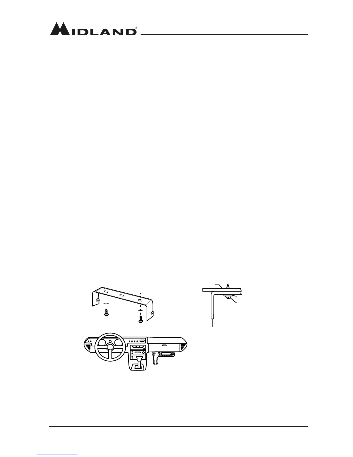
1� Install the Mounting bracket in the vehicle using the supplied selftapping screws (2pcs) and
at washers (2pcs).
2� Position the tranceiver, then insert and tighten the supplied hexagon screws�
-Double check that all screws are tightened to prevent vehicle vibration from loosening the
bracket or DBR2500�
Car body
Washer (M5)
Tapping screw
(M5x20mm)
Mounting bracket
Model DBR2500
page 7
midlandusa.com
DC POWER CABLE CONNECTION
Locate the power input connector as close to the DBR2500 as possible.
Mobile Operation
The vehicle battery must have a nominal rating of 12V� Never connect the tranceiver to a 24V
battery. Be sure to use a 12V battery that has sucient current capacity. If the current to the
tranceiver is insucient, the display may darken during transmission, or transmitting power may
be dramatically reduced�
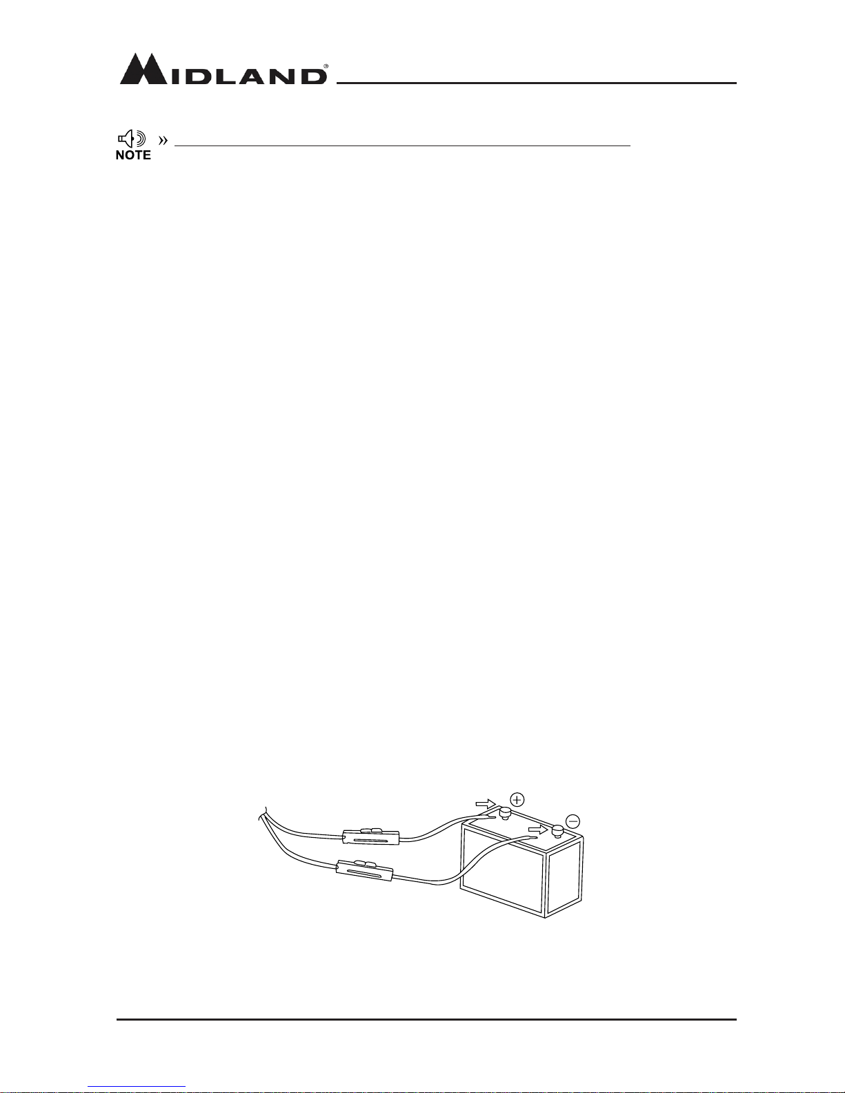
1� Route the DC power cable supplied with the radio directly to the vehicle’s battery terminals
using the shortest path from the DBR2500�
-We recommend that you do not use the cigarette lighter socket, as some cigarette lighter
sockets introduce an unacceptable voltage drop�
- The entire length of the cable must be insulated so that it is protected from heat,
moisture, and engine secondary (high voltage) ignition system and cables�
2� After installing the DC power cable, to avoid the risk of damage, please use heat-resistant
tape to tie together the DC power cable with the fuse box� Be sure to reinforce the entire
power cable with heat resistant tape�
3� In order to avoid the risk of a short circuit, please disconnect the connection with the
negative (-) battery terminal, then connect to the radio�
4.Conrm the correct polarity of the connections, then attach the power cable to the
battery terminals; red connects to the positive (+) terminal and black connects to the
negative (-) terminal�
- Use the full length of the cable without cutting o excess even if the cable is longer
than required� In particular, never remove the fuse holders from the cable�
Red
Black
5� Reconnect any wiring removed from the negative terminal�
6� Connect the DC power cable to the DBR2500’s power supply connector
- Press the connectors rmly together until the locking tab clicks.
page 8
midlandusa.com
Model DBR2500
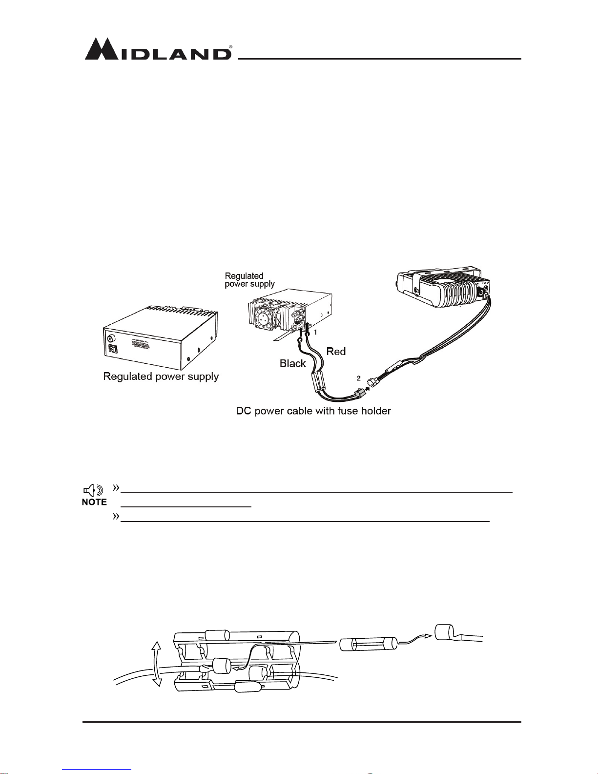
Fixed Station Operation
In order to use this DBR2500 for xed station operation, you will need a separate 13.8V DC
power supply (not included)�
The recommended current capacity of your power supply is 12A
1�Connect the DC power cable to the regulated DC power supply and ensure that the
polarities are correct� (Red: positive, Black: negative)
- Do not directly connect the DBR2500 to an AC outlet
- Use the supplied DC power cable to connect the DBR2500 to a regulated power
supply
- Do not substitute a cable with smaller gauge wires
2�Connect the DBR2500’s DC power connector to the connector on the DC power cable�
- Press the connectors rmly together until the locking tab clicks.
Before connecting the DC power to the DBR2500, be sure to switch the transeiver and
the DC power supply to OFF.
Do not plug the DC power supply into an AC outlet until you make all connections.
Replacing Fuses
If a fuse blows, determine the cause, then correct the problem� After the problem is
resolved, replace the fuse� If newly installed fuses continue to blow, disconnect the power cable
and contact Midland Radio Corporation for assistance�
Model DBR2500
page 9
midlandusa.com
Fuse Location Fuse Current Rating
Transceiver 10A
Supplied Accessory DC
power cable
10A
Only use fuses of the specied type and rating, failure to do so could cause damage to the
DBR2500�
If you use the transeiver for a long period of time when the vehicle battery is not fully
charged or when the engine is OFF, the battery may discharge, and may not have
sucient power to start the vehicle. Avoid using the transceiver in these conditions.
INSTALLING THE ANTENNA (Sold Separately)
Before operating, install an ecient, well-tuned antenna. The success of your radio will depend
largely on the type of antenna and its correct installation. Use a 50Ω impedance antenna and
low-loss coaxial feed-line that has a characteristic impedance of 50Ω, to match the DBR2500
input impedance� Coupling the antenna to the DBR2500 via feed-lines having an impedance
other than 50Ω reduces the eciency of the antenna system and can cause interference to
nearby broadcast television receivers, radio receivers, and other electronic equipment�
Transmitting without rst connecting an antenna or other matched load may damage
the DBR2500. Always connect the antenna to the DBR2500 prior to transmitting.
All xed stations should be equipped with a lightning arrester to reduce the risk of re,
electrical shock, and transceiver damage.
Specic installation requirements vary between vehicles. Use the following guidelines to install
the antenna�
*Where you locate your antenna does make a dierence.*
Some general rules for antenna location that can aid radio performance:
1� Metal surfaces covered by berglass or vinyl may aect radio range. Avoid these
locations�
2� Mount the antenna as high on the vehicle as possible� The higher the better�
3� If possible, mount the antenna in the center of whatever surface you choose�
4� Be sure the mounting location is clean and dry before installing the antenna�
5� Route the antenna cable through an accessible entry point, such as a rear door or
trunk opening�
page 10
midlandusa.com
Model DBR2500
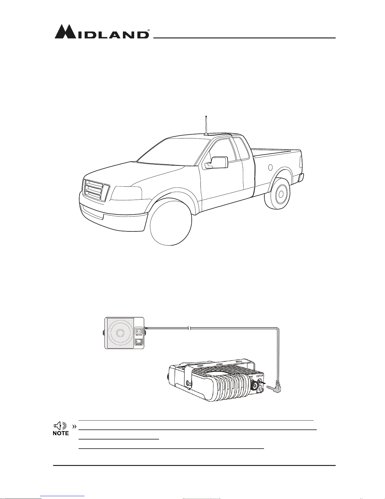
An ideal location of the antenna on a vehicle is shown below:
ACCESSORY CONNECTIONS
External Speaker (Sold Separately)
If you plan to use an external speaker, choose a speaker with an impedance of 8Ω. The
external speaker jack accepts a 3�5mm (1/8”) mono (2-conductor) plug�
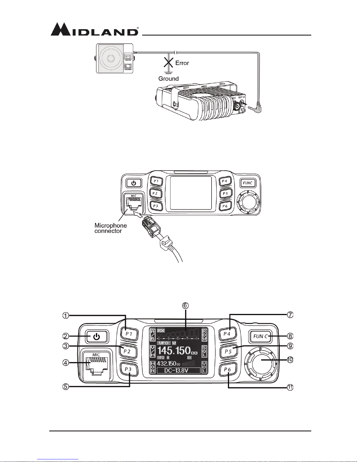
External speaker utilizes a double port BTL, please take care when connecting a
speaker to this port. Do not allow the speaker to make contact with a ground, as it
could damage the speaker.
The image on page 11 shows the incorrect connecting method.
6� When routing the antenna cable inside the vehicle, keep the cable away from noise
sources, such as the ignition system, gauges, etc�
7� Exercise care to prevent cable damage� Make use of existing gaskets, grommets and
weather stripping to protect the cable along its route�
Model DBR2500
page 11
midlandusa.com
Microphone
Insert the 8P8C (commonly “RJ45”) connector into the front of the DBR2500. Press rmly on
the plug until the locking tab clicks�
CONTROLS AND INDICATORS
Front Panel
page 12
midlandusa.com
Model DBR2500
Rear Panel
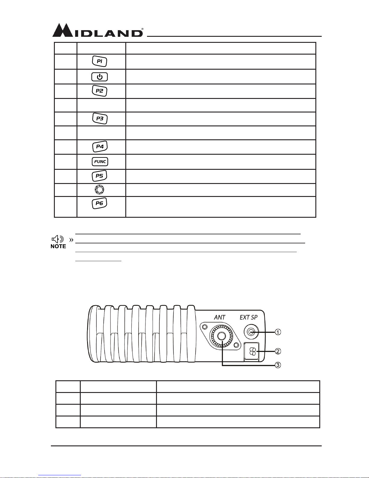
No. Button Functions
1 User programmable button (also referred to as a “[P:X] button”)
2 Power On / O / Mute
3 User programmable button (also referred to as a “[P:X] button”)
4 MIC Microphone Jack
5 User programmable button (also referred to as a “[P:X] button”)
6 LCD Display Displays channel / frequency / functions
7 User programmable button (also referred to as a “[P:X] button”)
8 Function button / Function group button
9 User programmable button (also referred to as a “[P:X] button”)
10 Channel switch / Push button / Key lock
11 User programmable button (also referred to as a “[P:X]
button”)
No. Feature Function
1 Ex-Speaker Jack Connect an optional external speaker
2 Power Cable Connect a standard DC power cable
3 Antenna Connector Connect a 50 ohm antenna
The term [P:X] button is used in reference to the user programmable P1, P2, P3,
P4, P5, and P6 buttons. When [P:X] is referenced in this manual, please press the
corresponding button (P1, P2, P3, etc.) for which the user has programmed the
desired function.
 Loading...