

Page 1

CT3000
DUAL BAND VHF / UHF MOBILE TRANSCEIVER
INSTRUCTION GUIDE
SPECIAL FEATURES
Output
Power
Flip function
180°
Extra loud
speaker
25W
3W
Page 2

Midland CT3000 instruction guide
Index
What’s in the box 1
Maintenance 1
Main features 2
Installing the radio 3
Installation 3
Power supply 3
Replacing fuses 4
Installing the microphone 4
Installing an antenna: 4
External speakers 4
Controls and display description 5
Display 6
Rear panel 7
Microphone 8
Main operations 9
Turning on and o 9
Volume adjustment 9
Selecting a band 10
Selecting the VHF or UHF band 10
Switching from frequency to channel mode 10
Frequency/channel adjustment 11
Frequency STEP selection: 11
Output power selection 12
Keypad lock 12
Menu settings 13
Page 3

Midland CT3000 instruction guide
Menu access 13
Menu: 14
List of the menu functions 15
Operating with repeaters and setting of CTCSS or DCS tones 17
Setting the frequency oset and its direction 17
Setting the CTCSS and DCS tones in TX: 17
Setting a CTCSS or DCS tone in RX 17
CTCSS tone chart 18
DCS codes chart 18
Transmitting a repeater access tone RPT TONE 19
Activating the frequency inversion 19
“Talk around” function 19
Memory channels 20
Storing a channel and its settings: 20
To recall a channel 20
Deleting a channel: 20
Scan function 21
Scan resume time 21
Selective call 21
DTMF functions 22
Transmitting a DTMF code 22
Transmitting a memory DTMF code 22
Changing a memory DTMF code and the tx time of DTMF codes 22
Selective calls with DTMF codes 22
Other functions 23
Activating/deactivating the keypad tones: 23
Setting the Time Out Timer: 23
Activating/deactivating the keypad lock: 23
Display backlight 23
Auto power-o 24
Page 4

Midland CT3000 instruction guide
Squelch opening 24
Selecting frequency mode, channel name mode, channel number
mode: 24
Setting a password 25
Inhibiting transmission 25
Flip function 26
Reset 26
Troubleshooting 27
Technical specifications 28
Page 5

Midland CT3000 instruction guide | 1
What’s in the box
• 1 CT3000 transceiver with power supply cable;
• 1 microphone;
• 1 mounting bracket;
• Fixing screws;
• 1 protection fuse;
If any item is missing, please verify with your Midland dealer.
Maintenance
CT3000 is an electronic product of exact design and should be treated with
care. The suggestions here below will help you to fulfill any warranty obligations
and to enjoy this product for many years.
• Do not attempt to open the radio for any reason! The radio’s precision mechanics and electronics require experience and specialized equipment; for
the same reason, the radio should under no circumstances be realigned as
it has been calibrated for maximum performance. Unauthorized opening of
the transceiver will void the warranty.
• Do not store the Radio under the sunshine or in hot areas. High temperatures can shorten the life of electronic devices, and warp or melt certain
plastics.
• Do not store the radio in dusty and dirty areas.
• Keep the Radio dry. Rainwater or damp will corrode electronic circuits.
• If it appears that the Radio diuses peculiar smell or smoke, please shut o
its power immediately.
• Do not transmit without antenna.
• Do not attempt to configure the transceiver while driving; it is very dangerous.
Page 6

2 | Midland CT3000 instruction guide
Main features
• VHF/UHF multi-band
• Operating modes: UHF-VHF, VHF-VHF or UHF-UHF
• Frequency bands (to set according to the country where you operate):
144-146 MHz & 430-440MHz (Rx / Tx).
• VHF and UHF bands displayed
• Channel number or channel number + frequency displayed
• Selectable output power: high (25W) middle (10W) or low (5W)
• Multi-color TFT display
• Flip display 180°
• Power supply 12,6V +/- 10%
• Metal chassis
• Programmable buttons
• Memory channel scan
• Digital automatic squelch adjustable in dierent levels
• Scan
• Dual watch
• Roger beep
• 200 memory channels
• TOT (time out timer)
• Adjustable backlight
• Automatic turning on/o
• Keypad lock
• Microphone with multi-function keypad and with RJ45 connector
• Software programmable (through the optional programming kit PRG3000 cod. C1352)
• 1750/2100/1000/1450Hz repeater access tones
• 104 + 104 DCS codes + 51 CTCSS tones
• Bandwidth selectable in 3 dierent levels 25 kHz/20 kHz/12,5 kHz
• Frequency inversion
• Frequency STEP: 2,5 kHz-5 KHz-6,25 kHz-10 kHz-12,5 kHz-20 kHz-25
kHz-30 kHz-50 kHz
• Frequency oset and oset direction selection
• Tx power level shown in the display
Page 7

Midland CT3000 instruction guide | 3
Installing the radio
Installation
Safety and convenience are the primary considerations for mounting any piece of mobile equipment. All controls must be readily available to the operator
without interfering with the movements necessary for safe operation of the
vehicle. To install the transceiver select a location that will minimize danger to
your passengers and yourself while the vehicle is in motion; the location should
be well-ventilated and shielded from direct sunlight.
1. Install the mounting bracket in the vehicle using the supplied self-tapping
screws and flat washers.
2. Mount the radio onto the bracket into the vehicle using the supplied
screws and tighten them properly considering the vibrations caused by
the vehicle.
Power supply
Be sure the transceiver is o.
On the rear of the radio you will see a bi-color power supply cable with a fuse
holder on the red cable.
This cable is supplied with a connector suitable for the connection to the radio
and vehicle’s battery or to an optional cigarette lighter plug.
In the direct-voltage power supply, it is very important to observe the polarity
even if the unit is protected against the accidental inversion.
Red = positive pole (+)
Black = negative pole (-)
The same colors are present on the battery and in the fuse box of the car.
Correctly connect the cable terminal to the battery.
Be sure to use a 12V vehicle battery that has sucient current capacity. Never
connect the transceiver to a 24V battery.
1. Connect the DC power cable to the regulated DC power supply and en-
sure that the polarities are correct.
2. Connect the DC power cable to the transceiver.
ATTENTION: To obtain best performances we recommend installing the radio in a
position with a good air circulation.
Page 8

4 | Midland CT3000 instruction guide
Replacing fuses
If the fuse blows, try to find a cause before replacing it. If necessary, contact a
service center for assistance.
The fuse on the rear of the radio has a current rating of 10A
10A 250V FUSE
IN-LINE FUSE HOLDER
Installing the microphone
Plug-in the microphone into the proper socket on the front panel of the radio.
If you prefer, the microphone can also be hung up thanks to its holder supplied
in the package.
Installing an antenna:
• Place the antenna as high as possible
• The longer is the antenna, the better will be the performance
• If possible, mount the antenna in the centre of the surface
• Keep the antenna cable away from noise sources, such as the iginition
switch, gauges, etc
• Prevent cable damage during antenna installation
Attention: To prevent damage, never operate your radio without connecting a pro-
per antenna. A periodical control of the cable and of the S.W.R. is recommended.
External speakers
If you use external speakers, the impedance must be 4 or 8 . The external
speaker jack accepts a 3.5mm mono plug.
Page 9
Midland CT3000 instruction guide | 5
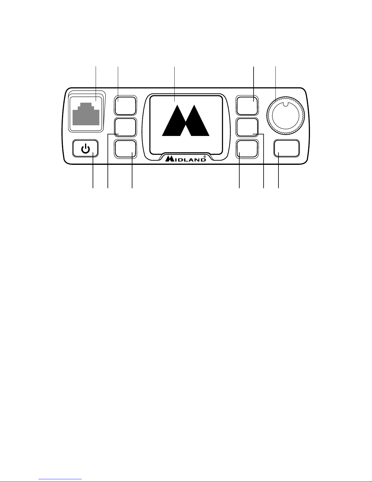
Controls and display description
1. Power ON/OFF control. Keep pressed to turn on/o the unit. Briefly
press to activate/deactivate the speaker.
2. P1 programmable key
3. P2 programmable key
4. P3 programmable key
5. P4 programmable key
6. P5 programmable key
7. P6 programmable key
8. FUNC key: function key. By pressing this button you will activate the
secondary functions shown on the front keys of the radio. Keep it pressed
to enter the radio’s menu
9. MIC: microphone connector. Plug-in the microphone or the program-
ming cable (optional) into this jack.
10. Main knob: keep it pressed to lock/unlock the keypad.
11. In normal conditions turn the knob to adjust the volume: clockwise to
increase it, counter-clockwise to reduce it. When you enter the menu,
rotate it to look through the menu options; inside the menu rotate it to
change the settings and then briefly press it for confirmation.
12. Multicolor graphic display.
P1
P2
P3
P4
P5
P6
FUNC
midlandeurope.com
CT3000
A
⁄
B
V
⁄
M
M
O
RX
VFO N
VFO W
•1••-••3••-••5••-••7••-••9•
144.000
145.150
9 2 5 10
1 7 6 83 4
11
Page 10
6 | Midland CT3000 instruction guide
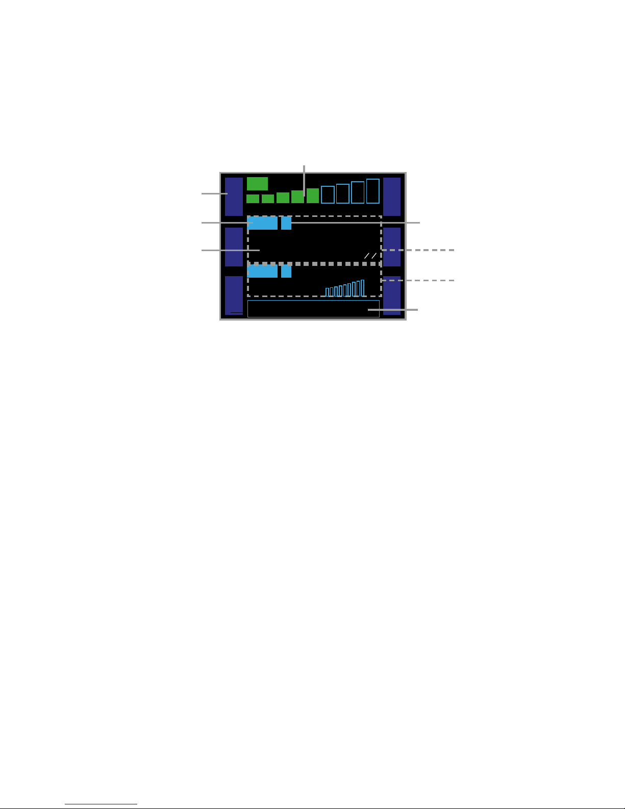
Display
A. Received signal strength indicator or power level indicator (in tx mode)
B. W/N: selected bandwidth. W: wide, N: narrow.
C. Functions associated to P1-P6 keys
D. Channel or band indicator
E. Channel or frequency in use
F. Here are located the main parameters that can be selected through the
function keys. By default the power voltage is indicated
G. Secondary display: second frequency in use and its signal strength
H. Main display: indicates the main frequency in use
A
⁄
B
V
⁄
M
M
O
N
R
E
V
S
Q
L
F
R
Q
RX
VFO N
VFO W
•1••-••3••-••5••-••7••-••9•
144.000
00
145.150
00
DC-12.3V
C
A
B
D
E
G
F
H
Page 11

Midland CT3000 instruction guide | 7
G
F
Rear panel
1. ANT: SO239 antenna connector.
2. EXT SPK: external speaker mike.
P1
P2
P3
P4
P5
P6
FUNC
ANT EXT SP
midlandeurope.com
CT3000
A
⁄
B
RX
VFO N
•1••-••3••-••5••-••7••-••9•
A
⁄
B
V
⁄
M
M
O
N
RX
VFO N
VFO W
•1••-••3••-••5••-••7••-••9•
144.000
145.150
1 2
Page 12

8 | Midland CT3000 instruction guide
Microphone
1. PTT: push to transmit
2. MIC: microphone location
3. UP/DOWN: push to change the frequency or to look through the set-
tings
4. KEY LOCK: Keypad lock
5. Band selection control
6. Band indicator led
2
1
3
4
MAIN
R/T R/T
MIC
4 5 6
7 8 9
PA
PB
PC
PD
0
1 2 3
6
5
Page 13

Midland CT3000 instruction guide | 9
Main operations
CT3000 is equipped with 6 programmable buttons: P1-P2-P3-P4-P5-P6.
They can be customised upon your needs; every button can be associated up
to 2 functions in 2 dierent menu at the same time.
By default the two menu are set as shown in the following charts:
Menu 1:
P1 A/B P4 REV
P2 V/M P5 SQL
P3 MON P6 FRQ
Menu 2:
P1 DIR P4 POW
P2 SFT P5 CDT
P3 SCN P6 BND
The functions associated to controls P1-P2-P3 will appear on the left side of
the display, while those activated with controls P4-P5-P6 will be displayed on
the right.
It is possible to change the functions associated to the P buttons through the
menu or the optional programming software.
To change the menu press FUNC.
Turning on and o
Push key for 1 second to switch on the radio. Push it again for 2 seconds to
turn it o.
Volume adjustment
Rotate the main knob clockwise to increase the volume and counter-clockwise
to reduce it.
Page 14

10 | Midland CT3000 instruction guide
Squelch adjustment
Squelch is used to mute the speaker when no signals are present. With the
squelch level set correctly, you will hear sound only while actually receiving a
signal. The higher the squelch level selected, the stronger must be the signals
in order to hear them.
To adjust the squelch press P5 of menu 1 or the control associated to SQL
function. Select the desired level by turning the main knob. You can choose
amongst 9 dierent levels: the most sensitive level is 1, while 9 is the least
sensitive one.
To confirm your selection push the main knob or wait for 10 seconds.
Selecting a band
The LCD display shows two frequencies: main band (A) and sub-band (B).
Press A/B (on the mike or on the radio) to select the desired band, A or B.
Everytime you press A/B, the band in use will be displayed in foreground and
with bigger font/characters.
Selecting the VHF or UHF band
In frequency mode it is possible to choose the operating band.
Keep pressed the A/B button to switch from VHF to UHF band and viceversa.
Switching from frequency to channel mode
When the transceiver is in stand-by mode, push the control associated to V/M
function to switch from frequency to channel mode. The mode will be changed
on the frequency in use (A or B).
In frequency mode VFO will appear on the display, while in channel mode the
display will show CH.
It is possible to use the frequency mode in band A and channel mode in band
B or viceversa.
Page 15

Midland CT3000 instruction guide | 11
Frequency/channel adjustment
In frequency mode you can change the frequency number with the main knob:
clockwise to increase the value and counter-clockwise to reduce it.
Each “clic” you hear from the knob corresponds to an increase or decrease of
the frequency (it is the same as the set STEP).
The desired frequency can also be manually set thanks to numeric keypad on
the microphone. If the frequency does not match with the current frequency
STEP, it will be automatically selected the nearest available frequency.
In channel mode it is possible to change the channel by turning the main knob.
Note: it is possible to adjust the frequency or the channel through the UP/DOWN
keys on the microphone.
Frequency STEP selection:
The correct frequency STEP allows you to select the exact rx frequency
through the main knob or the UP/DOWN buttons (if they are set for the
frequency mode).
The following frequency steps can be selected: 2,5 kHz - 5 KHz - 6,25 kHz 10 kHz - 12,5 kHz - 20 kHz - 25 kHz - 30 kHz - 50 kHz.
To set the desired frequency STEP press FUN for 2 seconds, select the option
FUNCTION MENU and then STEP. Now select the desired frequency STEP by
turning the main knob or the UP/DOWN controls.
To confirm push PTT or wait for 5 seconds.
Receiving
When the radio is turned on it immediately receives incoming signals; the
received signal strength is shown with the green bar in the upper side of the
display.
Make sure you set the proper frequency mode (VHF or UHF)!
Note: To immediately mute the speaker, press
. Audio: MT will appear in the lower
part of the display. Press again to enable the audio; now the display will show
AUDIO: Esc.
Page 16

12 | Midland CT3000 instruction guide
Transmitting
Before transmitting on the frequency or channel you have set, please check
they are not busy.
Press PTT and speak towards the microphone.
While you are transmitting, TX will appear on the display as well as the indicator
of the output power signal strength. Release the PTT to receive.
Output power selection
You can set three dierent output power levels: high (25W), middle (10W),
low (5W).
Press POW on the front panel of the radio. Everytime POW is pressed, the
output power indicator in the lower part of the display will show: POW:HI (high
power) , POW:LO (low power) , POW:MI (middle power).
The output power can be selected also with the microphone: press PC on the
mike; at every pressure, the output power will change.
Note: you can set dierent output powers for the two bands A and B.
Keypad lock
To lock the keypad keep pressed the main knob for 2 seconds. Key Lock will
appear in the lower side of the display.
Now all controls (radio and mike) will be locked except PTT.
To unlock the keypad keep presssed the main knob for 2 seconds again.
Page 17

Midland CT3000 instruction guide | 13
Menu settings
The menu allows you customize the radio functions and channels.
With FUNC key and main knob you can browse the menu and change its parameters.
The main knob in fact is not only a selector but also lets you enter the menu
and confirm the settings.
Menu access
1. Push FUNC button on the front panel for 2 seconds;
2. To select the desired function rotate the main knob;
3. Press the main knob to enter the option of the selected function;
4. Rotate the knob or press UP/DOWN on the mike to selecte the desired
option;
5. Confirm by pushing the knob.
6. To return back to the previous menu level press P3 - BACK on the radio.
7. Push P3 - BACK or wait for 5 seconds to exit the menu and to return to
stand-by condition.
Page 18

14 | Midland CT3000 instruction guide
Menu:
• FUNC MENU (to change the general settings of the radio)
1. BEEP
2. STEP
3. DSP
4. SQL
5. VOL
6. PWD
7. SCM
8. SCT
9. AOP
10. RDW
11. DIM
12. TOT
13. APO
14. RPTone
15. DIR
16. SPK
17. RTDF
18. RST
• CHAN MENU (to modify the settings of the channel in use)
1. RCDT
2. TCDT
3. POW
4. 5TENC
5. T-DEC
6. SIGNAL
7. BAND
8. REV
9. TALK
10. OFFSET
11. LOCK
12. TX
13. OWNID
• MINI KEY (To customize P1P6 controls)
1. HAND KEY
2. H-DIM
3. H-PA
4. H-PB
5. H-PC
6. H-PD
• DTMF MENU (to change the settings of DTMF codes)
1. CALL
2. SPEED
Page 19

Midland CT3000 instruction guide | 15
List of the menu functions
On the
display
Menu N. Function Selectable options
FUNC MENU
BEEP 1 Enabling the keypad tones ON 1,2,3,4,5 OFF
STEP 2 Channel spacing selection
12.5, 20, 25, 30, 50, 2.5,
5, 6.25, 10
DSP 3 Selection of the displayed mode CH,FRQ
SQL 4 Selection of the squelch level OFF,1,2,…,9
VOL 5 Setting of the speaker volume 1,2,3,…,36, 1,…
PWD 6
Enabling the password (default
password: 123456)
ON, OFF
SCM 7 Scan mode selection TO, CO, SE
SCT 8 Scan pause selection 5, 10, 15 sec.
AOP 9 Automatic turning on ON, OFF
RDW 10 Dual band/frequency enabling ON, OFF
DIM 11
Setting of the display and controls
backlight level
1, 2, 3
TOT 12 Time Out Timer OFF, 1, 2, …, … , 30 min.
APO 13 Automatic turning on OFF, 30, 60, 120 min.
RPTone 14 Repeater Tone 1750, 2100, 1000, 1450
DIR 15 To rotate 180° the display STAN, FAIL
SPK 16 Selecting the speaker in use M&H, HAND, MAIN
RTDF 17 Repeater mode ON, OFF
RST 18 Reset OPT, ALL
CHAN MENU
RCDT 1
Enabling the CTCSS and DCS tones
in RX
OFF, CTC, DCS
TCDT 2
Enabling the CTCSS and DCS tones
in TX
OFF, CTC, DCS
POW 3 Power level selection HI, LO, MI
5TENC 4 Enabling the PTT ID tones
OFF, BEGIN, END,
BEGIN AND END
T-DEC 5 Selecting the tones to send out OFF, DT, 5T
SIGNAL 6 Rx mode selection SQ, CDT
BAND 7 Bandwidth selection NAR, MID, WID
Page 20

16 | Midland CT3000 instruction guide
REV 8 RX/TX frequencies inversion OFF, ON
TALK 9
Activation of the talk around
function
OFF, ON
OFFSET 10 Frequency oset selection
OFF,
VHF : +/- 0 – 38 MHz
UHF : +/- 0 – 90 MHz
LOCK 11 Enabling the BCLO OFF, BU
TX 12 Enabling/disabling the transmission ON, OFF
OWNID 13 DTMF radio id
Through the optional
programming software
MINI KEY
In this menu it is possible to set the functions associated to keys P1-P6
Note: the option list may vary in case of modifications done with the optional programming kit.
Page 21

Midland CT3000 instruction guide | 17
Operating with repeaters and setting of
CTCSS or DCS tones
Setting the frequency oset and its direction
1. Select the rx frequency on the A or B band.
2. Set the oset direction: press the FUNC button for 3 seconds. Select
the desired oset with the main knob or by the UP/DOWN controls on
the microphone: CHANNEL MENU -OFFSET SET . The oset set by default is 5 MHz.
3. When the oset frequency is displayed press FUN. The display will show
-: this means that an oset with negative direction has been set, therefore
the tx frequency will be lower than the rx frequency. If you want to set an
oset with positive direction, press FUN again. Now + will appear on the
display and the tx frequency will be higher than the rx one.
4. For confirmation press the main knob.
Setting the CTCSS and DCS tones in TX:
1. Keep pressed FUNC on the front panel of the radio to access the radio
menu;
2. Select CHAN MENU;
3. Now select TCDT;
4. Select CTC o DCS with the main knob;
5. Set the desired CTCSS tone or DCS code by keeping pressed the main
knob for a few seconds
6. Turn the knob to select the desired tone; press it to set the tone.
7. Press P3-Back to exit the menu and return to stand-by mode.
Setting a CTCSS or DCS tone in RX
1. Push FUNC on the front panel to enter the radio menu;
2. Select CHAN MENU;
3. Select RCDT;
4. Now select CTC or DCS with the main knob;
5. Set the desired CTCSS tone or DCS code by keeping pressed the main
knob for a few seconds
6. Turn the knob to select the desired tone; press it to set the tone.
7. Press P3-Back to exit the menu and return to stand-by mode.
Page 22

18 | Midland CT3000 instruction guide
CTCSS tone chart
CTCSS tones
62,5 94,8 136,5 177,3 218,1
67,0 97,4 141,3 179,9 225,7
69,3 100,0 146,2 183,5 229,1
71,9 103,5 151,4 186,2 233,6
74,4 107,2 156,7 189,9 241,8
77,0 110,9 159,8 192,8 250,3
79,7 114,8 162,2 196,6 254,1
82,5 118,8 165,5 199,5
85,4 123,0 167,9 203,5
88,5 127,3 171,3 206,5
91,5 131,8 173,8 210,7
DCS codes chart
DCS codes (Normal and Inverted)
23 25 26 31 32 36 43 47
51 53 54 65 71 72 73 74
114 115 116 122 125 131 132 134
143 145 152 155 156 162 165 172
174 205 212 223 225 226 243 244
245 246 251 252 255 261 263 265
266 271 274 306 311 315 325 331
332 343 346 351 356 364 365 371
411 412 413 423 431 432 445 446
452 454 455 462 464 465 466 503
506 516 523 526 532 546 565 606
612 624 627 631 632 654 662 664
703 712 723 731 732 734 743 754
Page 23

Midland CT3000 instruction guide | 19
Transmitting a repeater access tone RPT TONE
1. Press PTT and DOWN at the same time to transmit a repeater access
tone. The tone set by default is 1750 Hz.
2. If you want to change the tone frequency follow these steps:
3. Press FUNC on the front panel to enter the radio menu;
4. Select option no. 1 FUNC MENU;
5. Select RPTONE;
6. Now you can choose amongst these options:
1750 Hz - 2100 Hz - 1000 Hz - 1450 Hz
7. Push the knob to confirm your selection;
8. Press P3 twice to exit the menu and return to standby condition.
Activating the frequency inversion
The frequency inversion can be activated only if a frequency oset (positive or
negative) is enabled.
1. Keep pressed FUNC to enter the radio menu;
2. Select option n. 2 CHAN MENU;
3. Select option n. 8 REV;
4. Now select ON with the main knob.
“Talk around” function
This function can be activated only if a frequency oset (positive or negative)
is enabled.
1. To activate the “talk around” keep pressed FUNC and then select option
no.9 TALK.
2. The icon A will be shown on the display.
3. Now you can communicate with the other users without using a repeater.
When the Talk Around function is activated, the frequency oset will be
disabled and the radio will transmit on the rx frequency.
Page 24

20 | Midland CT3000 instruction guide
Memory channels
CT3000 allows you to store up to 200 channels.
The channels let you store the frequency and data. So that you don’t have to
re-program the same data repeatedly and you can immediately tune on the
desired channels.
Storing a channel and its settings:
1. Select the channel you want to store
2. Set all the desired parameters
3. Keep pressed the P control associated to V/M for 2 seconds, the display
will show the channel number. If the channel blinks blue it means that the
memory is empty and you can store the desired settings; while if it blinks
red the channel is already busy but the settings can be overwritten.
4. Rotate the main knob to select the channel in which you want to overwrite the settings
5. Press V/M for 2 seconds for confirmation.
To recall a channel
1. Press the P button associated to the V/M function to enter the radio
memories
2. Turn the main knob to select the desired memory channel.
Note: In case you use the keypad you have to edit all 3 digits: for example, channel
1, you will edit “0”,”0”, “1”.
Deleting a channel:
1. Press the button associated to V/M function to enter the radio memories.
2. Select the channel you want to delete.
3. Keep pressed FUNC and the button associated to V/M function for 2
seconds.
This function is available only in frequency mode.
Page 25

Midland CT3000 instruction guide | 21
Scan function
CT3000 has 3 types of scanning:
• TO - Time-Operated scan: everytime a signal is detected, the radio will stop
scanning for a few seconds, then it will start scanning again on the other
frequencies even though the signal is still present.
• CO - Carrier-Operated scan: whenever a signal is detected, the radio will
stop scanning and will resume only after the signal disappears.
• SE - Search scan: the radio will stop scanning once a signal is picked up.
1. To select the desired type of scan, access the radio menu and follow these
steps: MENUFUNC MENUSCN
2. Select the desired parameter.
3. To start scanning press the P3 of menu 2 or the button associated to
SCN function.
4. To invert the scan direction use the main knob.
5. To stop scanning press any key on the front panel or PTT.
Scan resume time
It it possible to change the scan resume time. It goes from 5s up to 15s.
1. Enter the radio menu and follow this path:
MENUFUNC MENUSCT
2. Press the main knob to enter the options
3. Turn it to select the desired level.
4. Confirm your choice by pushing the main knob.
Selective call
You may sometimes want to hear calls from only specific persons or groups.
In this case, use the selective call function. This transceiver is equipped with
CTCSS tones and DCS codes. These selective calls allow you to ignore (not
hear) unwanted calls from other persons who are using the same frequency.
The transceiver unmutes only when it receives the signal having the same
CTCSS tone or DCS code.
CTCSS and DCS do not make your conversation private or scrambled. It only
relieves you from listening to unwanted conversations.
Page 26

22 | Midland CT3000 instruction guide
DTMF functions
CT3000 can store up to 16 DTMF codes with 16 digits.
The DTMF code memories can be changed with the optional programming
software.
Transmitting a DTMF code
1. Keep pressed PTT.
2. In tx mode press the controls corresponding to your DTMF code. You will
hear the code from the speaker of the radio.
Transmitting a memory DTMF code
This function is enabled only if you set your DTMF code by means of the programming software.
1. Select the desired customised DTMF code
2. Access the radio menu and follow these steps:
3. MENU DTMF MENUCALL
4. Select the desired DTMF code and confirm with the main knob.
5. Press the control associated to the CALL function (previously set in
HAND KEY menu)
Changing a memory DTMF code and the tx time of
DTMF codes
These functions can be enabled by means of the optional programming software.
Selective calls with DTMF codes
CT3000 can answer selective calls and open the squelch only in case you received a call with your DTMF code (DTMF ID or 5 Tone ID).
This function can be enabled through the programming software.
Note: DTMF settings can be changed only with the optional programming software.
Page 27

Midland CT3000 instruction guide | 23
Other functions
Activating/deactivating the keypad tones:
1. Enter the radio menu and follow these steps:
MENUFUNC MENUBEEP
2. Press the main knob to enter the options of the desired menu
3. Rotate the knob to select ON (keypad beep activated) or OFF (deactivated).
4. Confirm and save by pressing the knob.
Setting the Time Out Timer:
The Time Out Timer (TOT) automatically switches the radio in reception if you
talk for too long, after a pre-set time that can change from 1 minute up to 30
minutes.
Before stopping the transmission, CT3000 emits an acoustic alarm to warn
you and TOT OVER will appear on the display.
We suggest you keeping this function enabled, also because it is very useful to
prevent overheating of the radio.
1. Access the radio menu and follow this procedure:
MENUFUNC MENUTOT
2. Set the desired time and confirm by pushing the main knob.
Activating/deactivating the keypad lock:
Keep pressed the main knob for 3 seconds to lock/unlock the keypad.
Display backlight
The display backlight can be adjusted in 3 dierent levels: level 1 is the least
bright while level 3 is the brightest one.
1. Access the radio menu and select:
MENUFUNC MENUDIM
2. Set the desired level and confirm by pushing the main knob.
Page 28

24 | Midland CT3000 instruction guide
Auto power-o
You can set the automatic turning o for CT3000.
1. Enter the radio menu and follow this procedure:
MENU FUNC MENUAPO
2. Set the desired level: 30/60/120 minutes and confirm by pushing the
main knob.
3. Press P3 to exit the menu and return in stand-by mode.
Squelch opening
CT3000 automatically sets the squelch opening rules according to parameters that you set, such as for example CTCSS/DCS tones or DTMF codes.
If you want to modify the squelch opening rules, follow this procedure:
1. Enter the radio menu and follow these steps:
MENUCHAN MENUSIGNAL
2. Set the desired value and confirm by pushing MENU or PTT.
3. Press FUN to exit the menu and return in stand-by mode.
Selecting frequency mode, channel name mode, channel number mode:
1. Access the menu and follow these steps:
MENUFUNC MENUDSP
2. You can choose amongst the following options:
• FRQ Mode: the radio will be set in frequency mode; to switch to channel mode press V/M.
• CH Display Mode: channel mode. The channel number will be shown
in the display. It is not possible to switch to frequency mode through
the V/M button.
• MR Display Mode: the radio will be set to channel mode but the channel name will appear in the display. To switch to channel mode press
V/M.
3. Set the desired mode and confirm your selection by pushing the main
knob.
4. Press P3 to exit the menu and return in stand-by mode.
Page 29

Midland CT3000 instruction guide | 25
Setting a password
It is possible to set a password that will be required at the turning on of the radio.
1. Access the menu and follow this path:
MENUFUNC MENUPWD
2. Now select the desired option:
• ON (everytime the radio is turned on a password will be required)
• OFF (no password required)
3. Select the option and confirm by pushing the main knob.
4. Press P3 to exit the menu and return in stand-by condition.
Note: The password set by default is “000000”. The password can be changed
through the optional programming software.
Inhibiting transmission
In CT3000 the transmission can be inhibited: when this function is enabled,
the pressure of PTT won’t have any eect.
1. Enter the radio menu and follow this path:
MENUCHAN MENUTX
2. Choose one of these options:
• Tx ON: to enable the transmission
• Tx OFF: to disable the transmission.
3. Select the desired mode and confirm by pushing the main knob.
4. Exit the menu and return to stand-by mode by pressing P3.
Note: The selected option can dier from frequency to channel mode and from
VFO A to VFO B.
Note1: when the transmission is inhibited, if you press the PTT the radio won’t
transmit and will emit a warning tone. The display will show “FORBID TX”.
Dual Watch function
This functions allows to monitor two channels at the same time.
1. Enter the radio menu and follow this procedure:
MENUFUNC MENURDW
2. Select ON and confirm by pushing the main knob.
3. The dual watch function is activated and the radio will start monitoring
the two channels.
4. Everytime the radio detects a signal, the monitoring will stop and will resume once the signal disappears.
Page 30

26 | Midland CT3000 instruction guide
Flip function
Thanks to this function, the unit can be rotated 180° and the information on
the display will be properly shown.
To enable this function:
1. Keep pressed FUNC.
2. With the main knob access: FUNC MENU
3. Rotate the knob until option No.15 DIR.
4. Select it by pushing the knob.
5. Rotate and the current setting will turn green. You can change it by turning the knob.
6. Press it to confirm and exit by pushing P3.
Reset
1. Access the radio menu and follow this path:
MENUFUNC MENURST
2. Now choose between:
• ALL: to make a complete reset (settings and memories)
• OPT: to reset the settings only.
3. Set the desired option and confirm by pushing the main knob.
Page 31

Midland CT3000 instruction guide | 27
Troubleshooting
PROBLEM SOLUTION
The radio does not turn on Power supply cable disconnected or
defective. Check its status.
Fuse broken. Check the status of the
fuses in the radio and in your vehicle.
The display shows RX but the radio
does not receive
Verify the volume level is not too low!
Check that you have set the same
CTCSS tones and DCS codes of your
group.
The keypad does not work The keypad lock is activated
While you are communicating with
your group, you receive interferences
from other groups
Change the CTCSS tone or DCS
code of your group
Page 32

28 | Midland CT3000 instruction guide
Technical specifications
Frequency band 144-146MHz & 430-440MHz (Rx/Tx)
Memory channels 200
Power supply 12,6V DC ± 10%
Operating temperature -25°C to + 55°C
Operating mode monoband/dualband
Selectable output power 25W/10W/5W
Modulation F3E(FM)
Tones 51 CTCSS / 208 DCS
Duty cycle TX 5% / RX 5% / Stand-by 90%
Max frequency deviation ≤ ±5KHz
Spurious emissions -13dBm
Frequency stability ±1.0 ppm
Rx sensitivity @12dB SINAD < 0.3uV
Output power ≥ 3W
Dimensions 115x43x125 (LxAxP)
Weight (mike included) 925g
Specifications are subject to change without notice.
Page 33

Midland CT3000 instruction guide
Page 34

Midland CT3000 instruction guide
INFORMAZIONE AGLI UTENTI: Ai sensi dell’art. 13 del decreto legislativo
25 luglio 2005, n.151 “Attuazione delle Direttive 2002/95/CE, 2002/96/
CE e 2003/108/CE, relative alla riduzione dell’uso di sostanze pericolose nelle
apparecchiature elettriche ed elettroniche, nonché allo smaltimento dei rifiuti”. Il simbolo del cassonetto barrato riportato sull’apparecchiatura indica che
il prodotto alla fine della propria vita utile deve essere raccolto separatamente
dagli altri rifiuti. L’utente dovrà, pertanto, conferire l’apparecchiatura giunta a
fine vita agli idonei centri di raccolta dierenziata dei rifiuti elettronici ed elettrotecnici, oppure riconsegnarla al rivenditore al momento dell’acquisto di una
nuova apparecchiatura di tipo equivalente, in ragione di uno a uno. L’adeguata raccolta dierenziata per l’avvio successivo dell’apparecchiatura dismessa
al riciclaggio, al trattamento e allo smaltimento ambientalmente compatibile
contribuisce ad evitare possibili eetti negativi sull’ambiente e sulla salute e
favorisce il riciclo dei materiali di cui è composta l’apparecchiatura. Lo smaltimento abusivo del prodotto da parte dell’utente comporta l’applicazione delle
sanzioni amministrative di cui al dlgs. n.22/1997 (articolo 50 e seguenti del
dlgs. n.22/1997).
All articles displaying this symbol on the body, packaging or instruction manual
of same, must not be thrown away into normal disposal bins but brought to
specialised waste disposal centres. Here, the various materials will be divided
by characteristics and recycles, thus making an important contribution to environmental protection.
Alle Artikel, die auf der Verpackung oder der Gebrauchanweisung dieses
Symbol tragen, dürfen nicht in den normalen Mülltonnen entsorgt werden,
sondern müssen an gesonderten Sammelstellen abgegeben werden. Dort werden die Materialien entsprechend ihrer Eigenschaften getrennt und, um einen
Beitrag zum Umweltschutz zu liefern, wiederverwertet.
Page 35

Midland CT3000 instruction guide
Todos los artículos que exhiban este símbolo en el cuerpo del producto, en el
embalaje o en el manual de instrucciones del mismo, no deben ser desechados
junto a los residuos urbanos normales sino que deben ser depositados en los
centros de recogida especializados. En estos centros, los materiales se dividirán
en base a sus características y serán reciclados, para así poder contribuir de
manera importante a la protección y conservación del medio ambiente.
Tous les articles présentant ce symbole sur le corps, l'emballage ou le manuel
d'utilisation de celui-ci ne doivent pas être jetés dans des poubelles normales
mais être amenés dans des centres de traitement spécialisés. Là, les diérents
matériaux seront séparés par caractéristiques et recyclés, permettant ainsi de
contribuer à la protection de l'environnement.
Όλα τα προϊόντα στα οποία εμφανίζεται το ακόλουθο σύμβολο στο σώμα, τη
συσκευασία ή το εγχειρίδιο χρήσης τους, δεν πρέπει να εναποθέτονται στους κοινούς
κάδους απορριμάτων αλλά να προσκομίζονται στα ειδικά κέντρα αποκομιδής. Εκεί,
τα διάφορα υλικά θα πρέπει να διαχωρίζονται ανάλογα με τα χαρακτηριστικά και
τα ανακυκλούμενα υκλικά, συμμετέχοντας έτσι ουσιαστικά στην προστασία του
περιβάλλοντος.
Page 36

Prodotto o importato da: CTE INTERNATIONAL srl
Via. R.Sevardi 7, 42124 Mancasale - Reggio Emilia - Italia
www.midlandeurope.com
L’uso di questo apparato può essere soggetto a restrizioni nazionali (per l’uso in Italia è richiesta una
licenza amatoriale/individuale). Prima dell’uso leggere attentamente le istruzioni.
Produced or imported by: CTE INTERNATIONAL srl
Via. R.Sevardi 7, 42124 Mancasale - Reggio Emilia - Italy
Imported by: ALANNEVADA UK
Unit 1 Fitzherbert Spur Farlington Portsmouth Hants. P06 1TT - United Kingdom
www.nevada.co.uk
The use of this transceiver can be subject to national restrictions.
Read the instructions carefully before installation and use.
Vertrieb durch: ALAN ELECTRONICS GmbH
Daimlerstraße 1K - D-63303 Dreieich Deutschland
www.alan-electronics.de
Die Benutzung dieses Funkgerätes ist von den landesspezifischen Bestimmungen abhängig.
Vor Benutzung Bedienungsanleitung beachten.
Importado por: MIDLAND IBERIA, SA
C/Cobalt, 48 - 08940 Cornellà De Llobregat (Barcelona - España)
www.midland.es
El uso de este equipo puede estar sujeto a la obtención de la correspondiente autorización
administrativa. Antes de utilizar, lea atentamente el manual de uso.
Importé par: ALAN FRANCE S.A.R.L.
5, Rue Ferrie, Zac les Portes du Vexin 95300 Ennery - France
www.alan-midland.fr
L’utilisation de cet appareil peut être sujet à des restrictions nationales.
Avant l’utilisation, lire les instructions.
 Loading...