

Midland CT2000 Instruction Manual
DUAL BAND VHF / UHF MOBILE TRANSCEIVER
CT2000
SPECIAL FEATURES
Output
Power
Certified Extra loud
speaker
25W
3W
IP54
INSTRUCTION GUIDE

Midland CT2000 instruction guide
Index
What’s in the box 1
Maintenance 1
Caratteristiche principali 2
Installing the radio 3
Installation 3
Power supply 4
Replacing fuses 5
Installing an antenna 5
External speakers 5
Microphone 5
Controls and display description 6
Display 8
Rear panel 9
Microphone 9
Main operations 10
Turning on and o 10
Volume adjustment 10
Squelch adjustment 10
Selecting a band 10
Selecting the VHF or UHF band 10
Switching from frequency to channel mode 11
Frequency/channel adjustment 11
Frequency step selection 11
Receiving 12
Transmitting 12
Output power selection 12
Menu settings 13
Menu access 13
MENU 13
List of the menu functions 14

Midland CT2000 instruction guide
Operating with repeaters and setting
of CTCSS or DCS tones 16
Setting the frequency oset and its direction 16
Setting the CTCSS and DCS tones 16
Setting a sub-audio tone in rx 16
Quick setting of CTCSS and DCS tones 17
Transmitting a repeater access tone 17
Activating the frequency inversion 17
“Talk around” function 18
Memory channels 19
Storing a channel 19
Quick storage of a memory channel 19
To recall a channel 19
Deleting a channel 20
Scan function 20
Selective call 20
Setting CTCSS or DCS tones 21
Setting a sub-audio tone in rx 21
Shortcuts for activating CTCSS and DCS tones 21
CTCSS tones chart 22
DCS codes chart 22
DTMF functions 23
Transmitting a DTMF code 23
Transmitting a memory DTMF code 23
Changing a memory DTMF code 23
Changing the transmission time of DTMF codes 24
Selective calls with DTMF codes 24
Other functions 25
Activating/deactivating the keypad tones 25
Setting the Time Out Timer: 25
Activating/deactivating the keypad lock: 25
Display backlight 25
Auto power-o 26

Midland CT2000 instruction guide
Squelch opening 26
Selecting frequency mode, channel name mode, channel number
mode 26
Setting a password 26
Secondary display 27
Buttons on the front panel of the radio 27
Welcome message 28
Displaying the memory channel name or frequency 28
Selecting the transmission priorities 28
Inhibiting transmission 29
Acoustic sound for the secondary frequency 29
Reset 29
Troubleshooting 30
Technical specifications 31

Midland CT2000 instruction guide | 1
What’s in the box
• 1 CT2000 transceiver;
• 1 microphone with keypad;
• 1 mounting bracket;
• 1 power supply cable;
• Fixing screws;
• Mike holder
• 1 protection fuse
If any item is missing, please verify with your Midland dealer.
Maintenance
CT2000 is an electronic product of exact design and should be treated with
care. The suggestions here below will help you to fulfill any warranty obligations
and to enjoy this product for many years.
• Do not attempt to open the radio for any reason! The radio’s precision mechanics and electronics require experience and specialized equipment; for
the same reason, the radio should under no circumstances be realigned as
it has been calibrated for maximum performance. Unauthorized opening of
the transceiver will void the warranty.
• Do not store the Radio under the sunshine or in hot areas. High temperatures can shorten the life of electronic devices, and warp or melt certain
plastics.
• Do not store the radio in dusty and dirty areas.
• Keep the Radio dry. Rainwater or damp will corrode electronic circuits.
• If it appears that the Radio diuses peculiar smell or smoke, please shut o
its power immediately.
• Do not transmit without antenna.
• Do not attempt to configure the transceiver while driving; it is very dangerous.

2 | Midland CT2000 instruction guide
Main features
• VHF and UHF bands and channel name displayed
• Frequency bands (they will be set according to the country where you operate): 144-146 MHz & 430-440MHz (Rx / Tx).
• Operating modes: UHF-VHF, VHF-VHF or UHF-UHF
• 203 memory channels
• Multi-color graphic display
• 1750/2100/1000/1450Hz repeater access tones
• 104 + 104 DCS codes + 51 CTCSS tones
• Bandwidth selectable in 3 dierent levels 25 kHz/20 kHz/12,5 kHz
• Channel number or channel number + frequency displayed
• Frequency inversion
• Scan
• Frequency step: : 2,5 kHz - 5 KHz - 6,25 kHz - 7,5 KHz - 8,33 kHz - 10
kHz - 12,5 kHz - 15 kHz - 20 kHz - 25 kHz - 30 kHz - 50 kHz.
• Selectable output power: high (25W) middle (10W) or high (5W)
• Frequency oset and oset direction selection
• Tx power level shown in the display
• TOT (time out timer)
• Keypad lock
• IP54 protection grade, water and dust proof
• USB programmable thanks to the optional programming kit PRG510
Midland CT2000 instruction guide | 3
Installing the radio
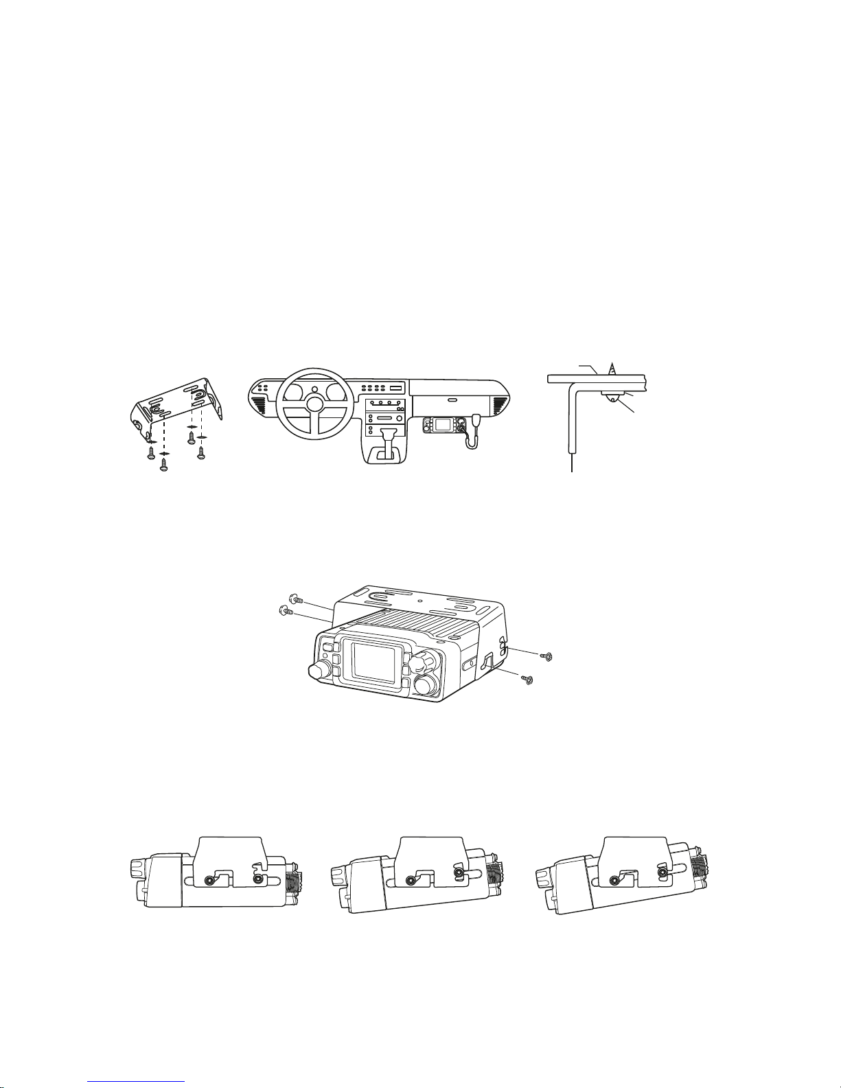
Installation
Safety and convenience are the primary considerations for mounting any piece of mobile equipment. All controls must be readily available to the operator
without interfering with the movements necessary for safe operation of the
vehicle. To install the transceiver select a location that will minimize danger to
your passengers and yourself while the vehicle is in motion; the location should
be well-ventilated and shielded from direct sunlight.
1. Install the mounting bracket in the vehicle using the supplied self-tapping
screws and flat washers.
2. Install the bracket into the vehicle using the supplied self-tapping screws
and washers.
3. Set an appropriate angle for the unit, using the 3 slots on the rear edge
of the bracket.
Car body
Rondelle
Viti
Staa di montaggio

4 | Midland CT2000 instruction guide
Power supply
Be sure the transceiver is o.
On the rear of the radio you will see a bi-color power supply cable with a fuse
holder on the red cable.
This cable is supplied with a connector suitable for the connection to the radio
and vehicle’s battery.
In the direct-voltage power supply, it is very important to observe the polarity
even if the unit is protected against the accidental inversion.
Red = positive pole (+)
Black = negative pole (-)
The same colors are present on the battery and in the fuse box of the car.
Correctly connect the cable terminal to the battery.
Be sure to use a 12V vehicle battery that has sucient current capacity. Never
connect the transceiver to a 24V battery.
Connect the DC power cable to the regulated DC power supply and ensure
that the polarities are correct.
Connect the DC power cable to the transceiver.
Attention: To obtain best performances we recommend installing the radio in a
position with a good air circulation.
Ext. power jack DC power cable
Midland CT2000 instruction guide | 5
Replacing fuses
If the fuse blows, try to find a cause before replacing it. If necessary, contact a
service center for assistance.
• The fuse on the rear of the radio has a current rating of 15A
• The fuse on the power supply cable has a current rating of 15A
Installing an antenna
• Place the antenna as high as possible
• The longer is the antenna, the better will be the performance
• If possible, mount the antenna in the centre of the surface
• Keep the antenna cable away from noise sources, such as the ignition
switch, gauges, etc
• Make sure you have a solid metal-to-metal ground connection
• Prevent cable damage during antenna installation
Attention: To prevent damage, never operate your radio without connecting a proper antenna. A periodical control of the cable and of the S.W.R. is recommended.
External speakers
If you use external speakers, the impedance must be 8 Ω. The external speaker
jack accepts a 3.5mm mono plug.
Make sure the speaker does not have a direct-to-ground connection.
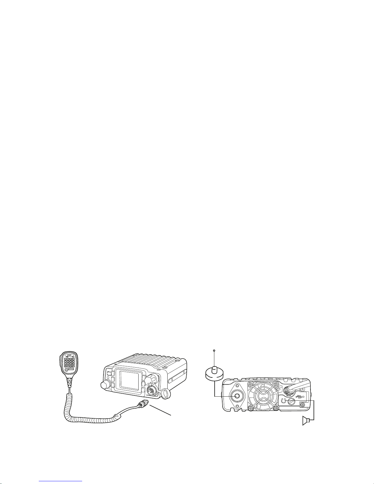
Microphone
Plug-in the supplied microphone to the proper connector on the front panel
of the radio.
The microphone can be also hung up thanks to its holder supplied in the package.
Microphone connector External speaker
6 | Midland CT2000 instruction guide
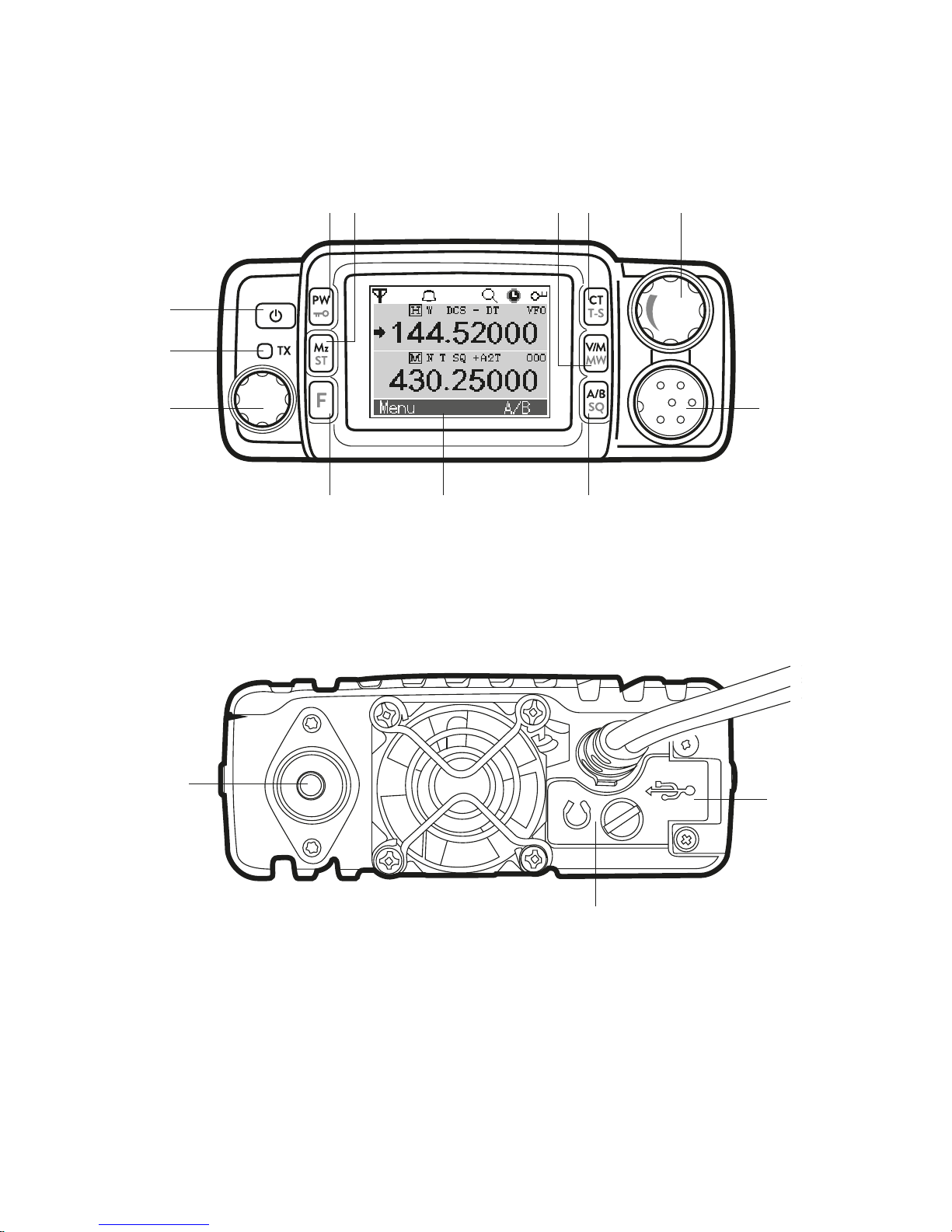
Controls and display description
1
2
3
4 7 10
12
118956
1
4 7 10
12
118956
6
1
13
14
15

Midland CT2000 instruction guide | 7
1. Power ON/OFF control. Keep pressed to turn on/o the unit.
2. TX LED: transmission led; it lights up red while the radio is transmitting
3. Main knob: it allows to select many settings. Rotate it to look through the
menu, change frequency, channel, scan direction, etc
4. F key: function key. By pressing this button you will activate the secon-
dary functions shown on the front keys of the radio.
5. Mz (ST): shortly press to change the frequency band of 1MHz in VFO
mode or to skip 10 channels forwards or backwards. Keep pressed to
adjust the frequency of 10MHz. Rotate the main knob to select the desired option and confirm by pushing Mz again.
6. PW/
: shortly push to change the level of the output power (high:
25W/middle: 10W/low: 5W). Long press: you will enter the frequency
oset setting; push the button again to enable you to change the oset
direction; rotate the knob to set the desired level and confirm your selection by pushing PW again.
: Press F and then PW to lock the keypad.
7. Multicolor graphic display.
8. CT/T-S: push this button to enable the CTCSS/DCS tones in tx and rx.
T-S: push F and then CT to select the desired tone.
9. V/M –MW. Short press: to switch from frequency to channel mode. Long
press: channel storage. MW: press F followed by V/M for a quick storage
of the first channel available.
10. A/B –SQ: shortly press to switch from the main display to the secondary
one. SQ: push F and then A/B to change the squelch level.
11. VOL: volume knob. Rotate the knob to select the desired volume level.
12. MIC: microphone connector. Plug-in the microphone into this jack.
8 | Midland CT2000 instruction guide
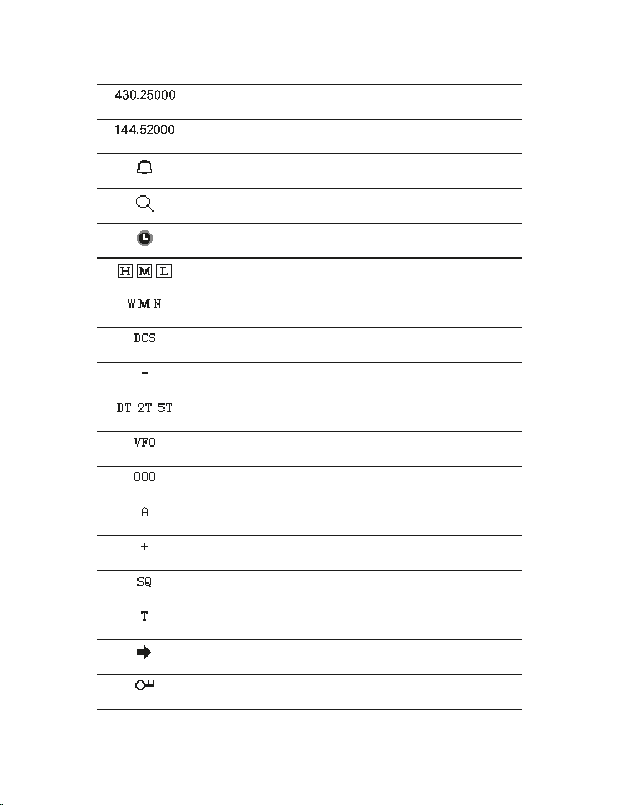
Display
Main display
Secondary display
Keypad beep activated
SCAN function activated
Auto power-o
Selected output power. H: high, M: middle, L: low
Selected bandwidth. W: wide, M: middle, N: narrow
DCS tone activated
Oset activated with negative direction
Selective call with DTMF code activated
Frequency mode
Memory channel
Talk Around function activated
Oset activated with positive direction
Activated CTCSS tones in rx
Activated CTCSS tones in tx
The icon indicates the display you are operating on
Keypad lock activated
 Loading...