

Page 1
Statie radio CB
Alan 8001
XT
Manual de utilizare in Limba Engleza
Page 2

E N G L I S H
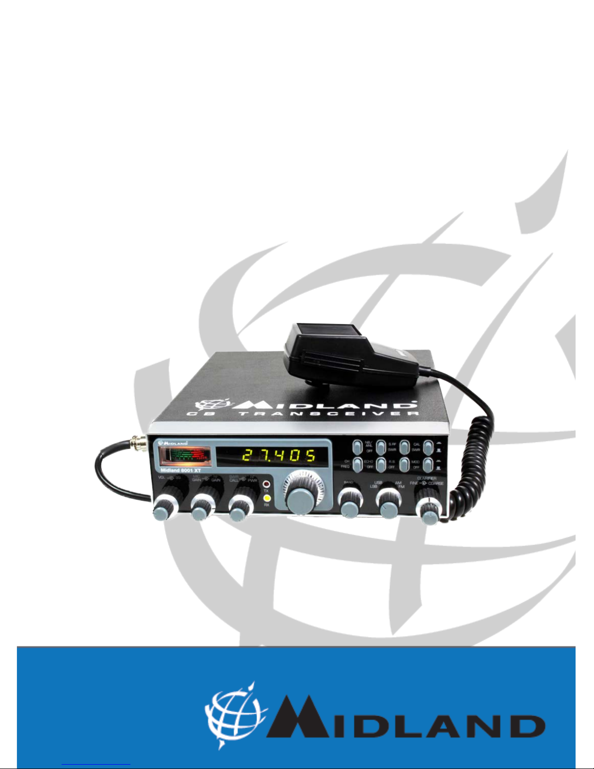
1
TABLEwOFwCONTENTSw
Installation ........................................................................................................................ 2
Location ........................................................................................................................ 2
Mounting the Connection ............................................................................................ 2
Ignition Noise Interference ............................................................................................ 2
Antenna ....................................................................................................................... 2
Tuning the Antenna for Optimum SWR ....................................................................... 3
External Speaker ......................................................................................................... 4
Replacing fuse ............................................................................................................. 4
Operation ........................................................................................................................ 4
Controls and Indicators ............................................................................................... 4
Front Panel .................................................................................................................... 4
Real Panel ..................................................................................................................... 6
P.T.T. Microphone ......................................................................................................... 6
Operating Procedure to Receive ................................................................................. 6
Operating Procedure to Transmit ................................................................................ 6
Receiving SSB signals .................................................................................................. 7
Roger Beep .................................................................................................................. 8
Warranty ...................................................................................................................... 8
Specif cations ................................................................................................................. 9
Page 3

E N G L I S H
2
INSTALLATION
LOCATION
Plan the location of the transceiver and microphone bracket before starting the installation.
Select a location that is convenient for operation and does not interfere with the driver or
passengers inside the vehicle. In cars, the transceiver is usually mounted below the dash
panel, with the microphone bracket beside it.
MOUNTING THE CONNECTION
The transceiver is supplied with a universal mounting bracket. When mounting the bracket
and radio inside your car, make sure it is mechanically strong. Also provide a good electrical
connection to the chassis of the vehicle. To mount the transceiver, proceed as follows:
1. After you have determined the most convenient location in your vehicle, hold the
transceiver with mounting bracket in the exact location you have chosen. If nothing
interferes with mounting it in the desired position, remove the mounting bolts. Before
drilling the holes, make sure nothing will interfere with the installation of the mounting
bolts.
2. Connect the antenna cable plug to the standard receptacle on the rear panel. Most CB
antennas are terminated with a PL 259 type plug and mate with the receptacle.
3. Connect the red DC power input wire (with the fuse) to +13.8 Vdc. This wire extends
from the rear panel. In automobile installation, +13.8 Vdc is usually obtained from the
accessory contact on the ignition switch. This prevents the set being left on accidentally
when the driver leaves the car, and also permits operating the unit without the engine
running. Locate the accessory contact on most ignition switches by tracing the power
wire from the AM broadcast receiver in the car.
4. Connect the black lead to +13.8 Vdc. This is usually the chassis of the car. Any convenient
location with good electrical contact (remove paint) may be used.
5. Mount the microphone bracket on the right side of the transceiver or near the transceiver,
using the two supplied screws. When mounting on a car, place the bracket under the
dash so the microphone is readily accessible.
IGNITION NOISE INTERFERENCE
The use of a mobile receiver at low signal levels is normally limited by the presence of
electrical noise. The primary source of noise in car installations is from the operated
with vehicle engine turned off. The unit requires very little current and therefore will not
signif cantly discharge the vehicle battery. In some installations, ignition interference may
be high enough to make good communications impossible. The electrical noise may come
from several sources. Many possibilities exist and variations between vehicles require
different solutions to reduce the noise.
ANTENNA
A vertically polarized, quarter-wavelength whip antenna provides the most reliable
operation and greatest range. Shorter, loaded-type whip antennas are more attractive,
compact and adequate for applications where the maximum possible distance is not
required. Also, the loaded whips do not present the problems of height imposed by a full
quarter-wavelength whip. Mobile whip antennas utilize the metal body of the vehicle as a
ground plane. When mounted at a corner of the vehicle they are slightly directional, in the
Page 4

E N G L I S H
3
direction of the body of the vehicle. For all pratical purposes, however, the radiation pattern
is nondirectional. The slight directional characteristic will be observed only at extreme
distances. A standard antenna connector (type SO 239) is provided on the transceiver for
easy connection to a standard PL 259 cable termination. If the transceiver is not mounted
on a metal surface, it is necessary to run a separate ground wire from the unit to a good
metal electrical ground in the vehicle. When installed in a boat, the transceiver will not
operate at maximum eff ciently without a ground plate, unless the vessel has a steel hull.
Before installing the transceiver in a boat, consult your dealer for information regarding an
adequate grounding system and prevention of electrolysis between f ttings in the hull and
water.
TUNING THE ANTENNA FOR OPTIMUM SWR
Since there is such a wide variety of base and mobile antennas, this section will strictly
concern itself to the various types of mobile adjustable antennas. Because the antenna
length is directly related to the channel frequency, it must be tuned to resonate optimally
all 40 channels of the transceiver. Channel 1 requires a longer antenna than Channel 40
because it is lower in frequency. Due to the various methods of adjusting antennas for
proper SWR we have chosen what we think is the optimum method:
A. Antennas with adjustment screws (set screws).
1. Start with the antenna extended and tighten the set screw lightly enough so that the
antenna can be lightly tapped with your f nger for easy adjustment.
2. Set your transceiver to Channel 2.0. Press the PTT (push-to-talk) switch, and tap
the antenna (making it shorter). The SWR meter will show a lower reading each time
the antenna is tapped. By continuing to shorten the antenna you will notice the SWR
reading will reach a low print and then start rising again. This means that you have
passed the optimum point for Channel 20. Adjust the antenna and again follow the
procedure above.
B. Antennas which must be cut to proper length.
1. Follow the same procedure as above, but adjust the length by cutting 2/3 mm increments
until a good match is obtained.
2. Be very careful not to cut too much at a time, as once it is cut, it can no longer be
lengthened.
3. The whip is easily cut by f lling a notch all the way around and breaking the piece off
with pliers.
If you are having diff culties in adjusting your antenna, check the following:
A. All doors must be closed when adjusting the antenna.
B. Make sure the antenna base is grounded.
C. Check your coaxial cable routing (it may be pinched when routed into the car).
D. Try a different location on your car (keeping in mind the radiation pattern you wish).
E. Is the antenna perfectly vertical?
F. Try a different location in your neighbourhood. Stay away from large metal objects when
adjusting (metal telephone or light posts, fences etc.)
WARNING: The transceiver will operate into a SWR of 2 to 1 indef nitely and sustain a
SWR of 20: 1 for a maximum of 5 minutes at rated operating conditions.
Page 5

E N G L I S H
5
4. RF GAIN CONTROL (outer dual concentric). It reduces the gain of the RF amplif er
under strong signal conditions.
5. SWR CAL CONTROL (inner dual concentric). In order to achieve maximum radiated
power and the longest range, it is important that your antenna is in good conditions,
properly adjusted and matched to your transceiver. The built-in SWR (standing wave
ratio) meter lets you easily measure your operating antenna conditions. To operate
this function, connect your antenna to the output connector. Select a channel near the
middle of the band such as 21 or the channel you plan to use most frequently. Set the
16 switch on the SWR position, and the 14 switch on the SWR CAL position. Press and
hold the microphone push-to-talk button and using the SWR CAL control, adjust the
meter indicator on the CAL position. Then, without releasing the P.T.T. button, set the 14
switch on the OFF position and read the SWR indicated. The number 1 should be the
ideal value. Generally speaking, readings up to 3 are acceptable, but over 3 indicates
that you are losing radiated power and antenna adjustment may be necessary.
6. RF POWER CONTROL (outer dual concentric). This control enables you to adjust
the RF output power continuously over the range of 1 watt through 12 watts (SSB).
7. RX INDICATOR. This indicator will be illuminated when the unit has been set in RX
mode.
8. TX INDICATOR. This indicator will be illuminated when the unit has been set in TX
mode.
9. CHANNEL SELECTOR. This switch selects anyone of the forty Citizens Band channels
desired. The selected channel appears on the LED readout directly above the Channel
Selector knob.
10. BAND SELECTOR. To skip 10 channels.
11. MODE (FM/AM/USB/LSB) SWITCH. This switch is used to select the LSB, USB,
AM, FM mode of operation. Unless the station with which communication is desired is
equipped with SSB, the AM or FM mode is normally used. The mode switch changes the
mode of operation of both transmitter and receiver simultaneously. Turn to‘’Receiving
SSB signals’’ for a further explanation of single sideband.
12. CLARIFIER. This control allows variation of the receiver operating frequencies above
and below the assigned frequency. Although this control is inteded primarily to tune in
SSB signals, it may be used to optimize AM/FM signals as described in this manual.
Coarse operates both TX/RX but Fine only in RX.
13. MODE/OFF SWITCH. In MOD. position, the meter will show the modulation percentage,
while in OFF position it will show the RF output power.
14. SWR CAL/OFF SWITCH. This control, when in SWR/CAL position, is used to tune the
SWR-meter.
15. ROGER BEEP SWITCH. When this switch is placed in the ROGER BEEP position,
your radio automatically transmits the audio signal at the end of your transmission. The
listener can note easily your transmission is over through the signal.
16. S-RF/SWR SWITCH. When set in S-RF position, the meter in RX mode shows the
intensity of the received signal; during TX mode it shows the output power. In SWR
position, it allows to measure the SWR value after tuning.
17. ECHO SWITCH (OPTIONAL). Set this switch to ECHO when you desired to add an
ECHO effect to your transmitting voice. This switch has no effect on receiving.
18. NB/ANL-OFF SWITCH. In NB/ANL position, it activates the automatic noise limiter
and operates as a f lter; in OFF position it deactivates the function.
19. FREQ-CHANNEL SWITCH. In FREQ position, this control activates the frequency
meter; in CHANNEL position, the 2 digits indicate the selected channel.
20. NOT USED.
Page 6

E N G L I S H
6
21. DISPLAY FREQUENCY METER. It shows the operating frequency and the selected
channel.
22. INDICATOR. This meter indicates the received signal strength, the SWR level, the
transmitter RF output power, the TX modulation percentage; furthermore it allows the
SWR-meter tuning.
REAR PANEL
23. POWER SUPPLY. Accepts 13.8 VDC power cable with built-in fuse to be connected.
24. EXT SP. Accepts 4 to 8 ohm, 5 watt external speaker to be connected. When external
speaker is connected to this jack, the built-in speaker is automatically disconnected.
25. ANTENNA. Accepts 50 ohm coaxial cable with a PL-259 type plug to be connected.
PRESS-TO-TALK MICROPHONE
The receiver and trasmitter are controlled by the press-to-talk switch on the microphone.
Press the switch and the trasmitter is activated, release switch to receive. When
transmitting, hold the microphone 10 cm from the mouth and speak clearly in a normal
‘’voice’’. The radios come complete with low-impedance (500 ohm) dynamic microphone.
OPERATING PROCEDURE TO RECEIVE
1. Be sure that power source, microphone and antenna are connected to the proper
connectors before going to the next step.
2. Turn the unit on by tuning the VOL control clockwise on your transceiver.
3. Set the VOLUME for a comfortable listening level.
4. Set MODE switch (11) to the desired mode.
5. Listen to the background noise from the speaker. Turn the SQUELCH control slowly
clockwise until the noise just disappears (no signal should be present). Leave the
control at this setting. The SQUELCH is now properly adjusted. The receiver will remain
quiet until a signal is actually received. Do not advance the control too far, or some of
the weaker signals will not be heard.
6. Set the CHANNEL switch to the desired channel.
7. Set the RF gain control fully clockwise for maximum RF gain.
8. Adjust the CLARIFIER control to clarify the SSB signals or to optimize AM/FM signals.
- POWER+
EXT.SP.
ANT
25 24
23
Page 7

E N G L I S H
7
OPERATING PROCEDURE TO TRANSMIT
1. Select the desired channel of transmission.
2. Set the MIC GAIN control fully clockwise.
3. If the channel is clear, depress the push-to-talk switch on the microphone and speak in
a normal voice.
RECEIVING SSB SIGNALS
There are four types of signals presently used for communications in the Citizens Band:
FM, AM, USB, and LSB. When the MODE switch on your unit is placed in the AM position,
only standard double-sideband and in FM position, only frequency deviation, full carrier
signals will be detected. An SSB signal may be recognized while in the AM or FM mode by
its characteristic ‘’Donald Duck’’ sound and the inability of the AM or FM detector to produce
an intelligible output. The USB and LSB modes will detect upper sideband and lower
sideband respectively, and standard AM signals. SSB reception differs from standard AM
reception in that SSB receiver does not require a carrier or opposite sideband to produce
an intelligible signal. A single-sideband transmitted signal consists only of the upper or the
lower sideband and no carrier is transmitted. The elimination of the carrier from the AM
signal helps to eliminate the biggest cause of whistles and tones heard on channels which
make even moderately strong AM signals unreadable. Also, SSB takes only half of an AM
channel, therefore two SSB conversations will f t into each channel, expanding the 40 AM
channels to 80 SSB channels. The reduction in channel space required also helps in the
receiver because only half of the noise and interference can be received with 100% of the
SSB signal.
An SSB signal may be received only when the listening receiver is functioning in the same
mode. In other words, an upper sideband signal (USB) may be made intelligible only if the
receiver is functioning in the USB position. If a lower sideband (LSB) signal is heard when
the receiver is in the USB mode, no amount of tuning will make the signal intelligible. The
reason for this may be understood if you consider that when modulation is applied to the
transmitter’s microphone in the USB mode, the transmitter’s output frequency is increased
whereas in the LSB mode the transmitter’s output frequency is decreased. The result in
listening to the receiver is that when the MODE switch is in the proper position (either
USB, or LSB), a true reproduction of single tone of modulation will result, and if the tone is
increased in frequency (such as a low-pitched whistle a high-pitched whistle) you will hear
the increase in the output tone of the receiver.
If the incorrect mode is selected, an increase in tone of a whistle applied to the transmitter
will cause a decrease in the resultant tone from the receiver. Thus when a voice is used in
place of a whistle or tone, in the proper listening mode the voice will be received correctly
whereas in the incorrect mode, the voice will be translated backwards and cannot be
made intelligible by the voice lock control. When listening to AM transmission, a correct
sideband is heard in either mode since both upper and lower sidebands are received.
Once the desired SSB mode has been selected, frequency adjustment may be necessary
in order to make the incoming signal intelligible, the CLARIFIER control allows the operator
to vary frequency above and below the exact-center frequency of the received signal.
If the sound of the incoming signal is high or low pitched, adjust the operation of the
CLARIFIER. Consider it as performing the same function as a phonograph speed control.
When the speed is set too high, voices will be high-pitched and if set too low, voices will
be low-pitched.
Also, there is only one correct speed that will make a particular record produce the same
sound that was recorded. If the record is played on a turntable that rotated in the wrong
Page 8

E N G L I S H
8
direction (opposite sideband) no amount of speed control (CLARIFIER) will produce an
intelligible sound. An AM signal received while listening in one of the SSB modes will
produce a steady tone (carrier) in addition to the intelligence, unless the SSB receiver
tuned to exactly the same frequency by the CLARIFIER control.
ROGER BEEP
When your transceiver is in normal operation, your radio automatically trasmits the audio
signal at the end of your transmission. The listener can note easily that your transmission
is over through the signal. Please note that this ROGER BEEP transmits 0.15-second at
the moment PRESS-TO-TALK SWITCH KNOB is turned off.
WARRANTY
This product is covered by European warranty rulings and should be returned to the place
where purchased for repair or replacement if not repairable.
In the event it that it is returned to us by your supplier then we will either repair or replace
within 15 working days from receipt. During the Warranty period, the Manufacturer or the
authorized customers service will, in accordance with this Limited Warranty , remedy defects by repair or replace the product. This Limited Warranty is only valid and enforceable
in the country where the user has purchased the product. The warranty period lasts 2 years
and starts at the time of product’s original purchase by the f rst end-user. In the event of a
product defect, please return it to the authorized customer service or to the Manufacturer
himself.
To make use of this warranty, it is necessary to return to the authorized service centre:
› The affected product (or accessory)
› The original proof of purchase, which clearly indicates the name and address of the
seller and the date and place of purchase.
The warranty does not cover normal wear and tear of the product, defects or damage
caused to the Product by misuse with, or connection to, any product, accessory software
and/or services not produced or supplied by the manufacturer or by use of the product for
any other use than for intended use of the product. The warranty is not enforceable if the
product has been opened, modif ed or repaired by anyone other than the authorized service centre; if it is repaired using unauthorized spare parts or if the serial number has been
removed, erased, defaced, altered or is illegible. The warranty is not enforceable if the
product has been exposed to moisture, to dampness or to extreme thermal or environmental conditions or to corrosion, to oxidation, to spillage of food or liquid or to inf uence from
chemical products.
VOCE
P.T.T. RILASCIATO
BEEP
O.15 Sec
TX
RX
P.T.T. ATTIVO
VOICE
PRESS TO TALK ON PRESS TO TALK OFF
Page 9

E N G L I S H
9
SPECIFICATIONS
GENER AL
Channels 40 CH/AM/FM/USB/LSB
Frequency Range 26.965 ÷ 27.405
Frequency Control Phase Lock Loop (PLL) synthesizer
Frequency Tolerance 0.005
Frequency Stability 0.001%
Operating Temperature Range -10° C to + 55° C
Microphone Plug-in dynamic with push-to-talk switch and coiled cord
Input Voltage 13.8 V DC nominal, ± 10%
Current consumption Transmitter: AM/FM 4A -SSB PEP output, 6A
Receiver: Squelched, 0.6A -Maximum audio output, 1.2A
Size 6 cm (H) x 20 cm (W) x 23.5 cm(D)
Weight 1.900 Kg
Antenna Connector UHF, SO 239
Meter (3-in-1) Illuminated; indicates relative output power, received signal
strength and SWR.
Duty cycle 5/5/90
TRANSMIT TER
Power Output SSB: 12 W - FM: 4W - AM: 4W
Modulation AM/FM/SSB
Intermodulation SSB 3rd order, more than -25 dB
Distortion 5th order, more than -35 dB
SSB Carrier Suppression 55 dB
Unwanted Sideband 50 dB
Frequency Response AM and FM: 300 Hz to 3000 Hz
Output Impedance 50 Ohms, unbalanced
Output Indicators Meter shows relative RF output power and SWR. Transmit
LED glows red when trasmitter is working
RECEIVER
Sensitivity SSB: 0.25 µV for 10 dB (S+N)/N
AM: 0.6 µV for 20 dB (S+N)/N
FM: 0.6 µV for 20 dB (S+N)/N
IF Frequency AM/FM: 10.695 MHz 1st IF,
455 kHZ 2nd IF - SSB: 10.695 MHz
Adjacent-Channel Rejection 60 dB AM/FM & 70 dB SSB
RF Gain Control 45 dB adjustable for optimum signal reception
Automatic Gain Control (AGC) Less than 10 dB change in audio output for inputs from 10
to 100.000 microvolts
Squelch Adjustable; thereshold less than 0.5 µV
ANL Switchable
Clarif er Range Coarse (RX) ±5 KHz; Fine (RX) ±1 KHz
Audio Output Power 4 watts into 8 ohms
Frequency Response 300 ÷ 3 KHz
Built-in Speaker 8 ohms, round
External Speaker (Not Supplied) 8 ohms; disables internal speaker when connected
Specifications are subject to change without notice.
A readily accessible disconnect device shall be incorporated in the installation wiring.
The disconnect device shall disconnect both poles simultaneously.
 Loading...