

Page 1
Alan 78 Pro
” GUIDA ALL‘USO
” INSTRUCTION GUIDE
” BEDIENUNGSANLEITUNG
” MANUAL DE INSTRUCCIONES
” GUIDE D‘UTILISATION
” INSTRUKCJA OBSŁUGI
” MANUAL DE UTILIZARE
Page 2

Page 3

SOMMARIO
DESCRIZIONE COMANDI ............................................................................................................................................................................................................................. 2
PANNELLO POSTERIORE ..................................................................................................................................................................................................................... 3
MICROFONO ............................................................................................................................................................................................................................................ 3
INSTALLAZIONE .................................................................................................................................................................................................................................................4
COLLEGAMENTO ELETTRICO ............................................................................................................................................................................................................ 4
INSTALLAZIONE DELL’ANTENNA ......................................................................................................................................................................................................4
SOSTITUZIONE DEL FUSIBILE .............................................................................................................................................................................................................. 4
ISTRUZIONI DI FUNZIONAMENTO ............................................................................................................................................................................................................4
SELEZIONE BANDE DI FREQUENZA ..........................................................................................................................................................................................................5
TABELLA BANDE DI FREQUENZA ...................................................................................................................................................................................................... 5
CARATTERISTICHE TECNICHE ......................................................................................................................................................................................................................5
I
1
Page 4

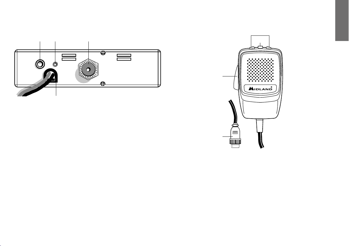
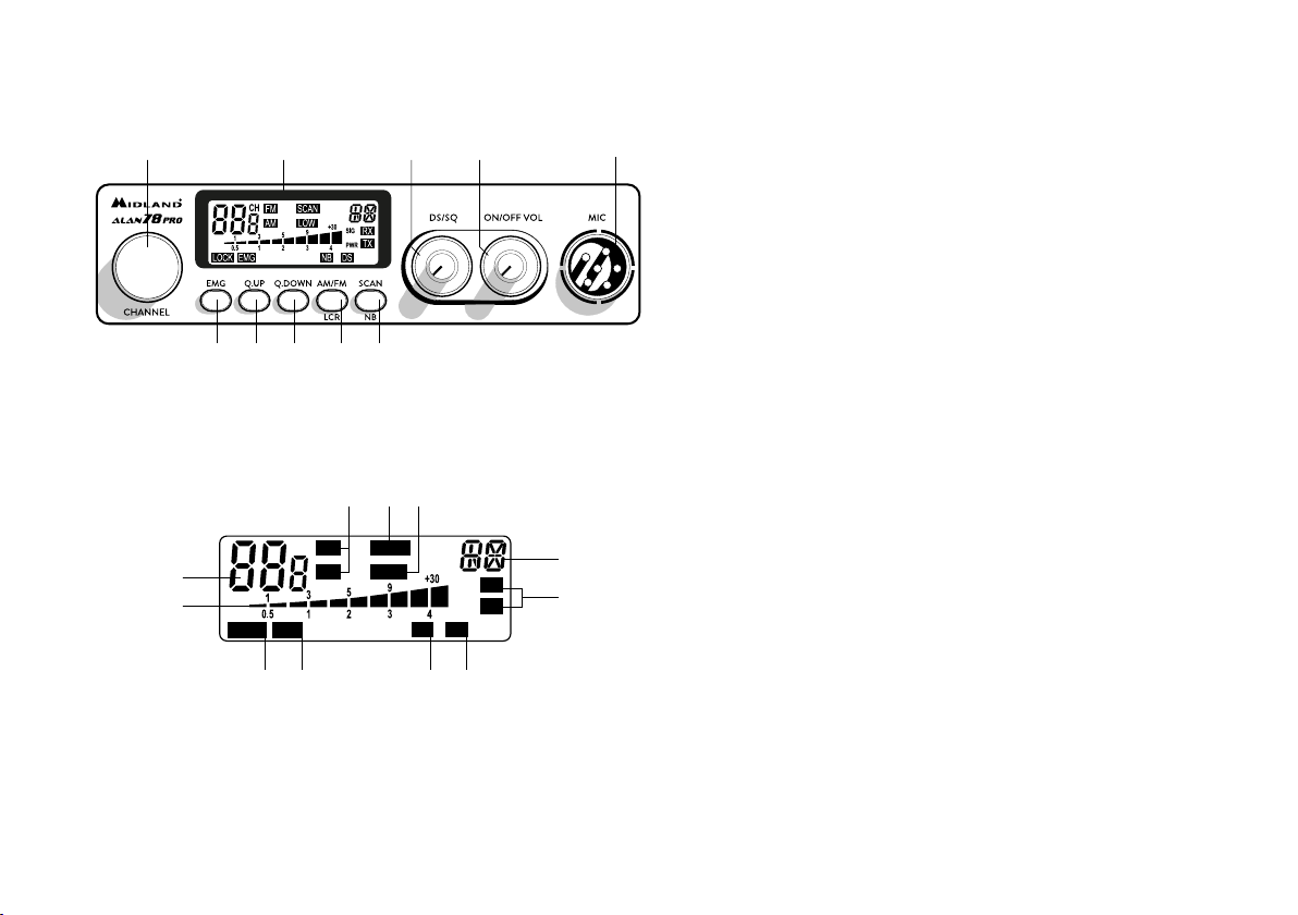
DESCRIZIONE COMANDI
1 3 5 4 2
109876
1. Ricerca manuale canali
2. Presa microfono: Inserire lo spinotto nell’apposita presa.
3. Display retroilluminato multifunzione
C E H
CH
FMAMSCAN
A
B
LOW
SIG
PWR
NBLOCK EMG DS
RX
TX
KJFI
Le indicazioni riportate possono differenziare in base al lotto di produzione.
A. Numero canali selezionati
B. Indicatore di intensità del segnale ricevuto e di potenza di segnale tra-
smesso
C. AM/FM: indicatore del modo di emissione. Le icone lampeggiano se la
funzione NOISE BLANKER è stata attivata (per versione senza NB e
2
G
D
DS sul display).
D. RX/TX: indicatore ricezione (RX) e trasmissione (TX).
E. SCAN: indicatore funzione SCAN attivata
F. EMG: indicatore lampeggiante canale d’emergenza attivato
G. Indica la banda di frequenza selezionata.
H. LOW: viene visualizzato quando la radio trasmette in bassa potenza (con-
dizione che si verifica solo per determinate bande di frequenza – vedi
tabella bande).
I. LOCK: Attivazione del blocco tastiera (UP/DOWN) del microfono.
J. NB: indicatore Noise Blanker attivato (per versione che lo supporta)
K. DS: indicatore Digital Squelch attivato (per la versione che lo supporta)
4. Manopola ON/OFF-VOLUME: Posizione ‘’OFF’’: Apparato spento;
Posizione ‘’Volume’’: Ruotando la manopola, regolare il volume al livello desiderato.
5. Manopola ‘’DS/SQ’’ permette di eliminare i fastidiosi rumori in fase di ricezio-
ne e di operare in modalità DS (Digital Squelch).
6. Pulsante “EMG”: Canale d’emergenza: premendo questo tasto ci si posizio-
nerà automaticamente sul canale 9 (canale d’emergenza). Sul display lampeggerà “EMG” e non sarà possibile cambiare accidentalmente il canale.
7. PULSANTE “Q.UP”: Per selezionare rapidamente i canali verso l’alto.
8. PULSANTE “Q.DOWN’’: Per selezionare rapidamente i canali verso il basso.
9. Pulsante “AM/FM”(LCR): Per selezionare il modo di emissione (AM/FM). Se
lo si preme all’accensione con il tasto “SCAN”, seleziona la banda operativa.
Le relative scelte saranno visualizzate sul display. Se si seleziona un banda di
frequenza che opera solamente la modalità FM, il tasto “AM/FM” attiva la
funzione LCR (richiamo ultimo canale selezionato).
10. Pulsante “SCAN/NB”: tramite questo comando si potrà ricercare automati-
camente un canale occupato.
• Ruotare lo Squelch in senso orario fino a quando non sparisce il rumore di
fondo.
• Premere il pulsante “SCAN”. Il ricetrasmettitore scansionerà automaticamente e ripetutamente tutti i canali fino a quando non troverà un
canale occupato.
Se lo si preme all’accensione con il tasto “AM/FM”, seleziona la banda ope-
rativa. Le relative scelte saranno visualizzate sul display. Tenendo premuto il
pulsante, si attiva il filtro Noise Blanker.
Page 5
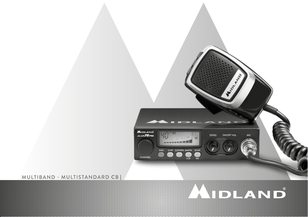
PANNELLO POSTERIORE
MICROFONO
I
13 12 11
EXT
S. METER
ANTENNA
14
11. Connettore antenna: È previsto il connettore SO 239.
12. Presa S. METER: Permette il collegamento di uno strumento esterno.
13. Presa EXT: Presa altoparlante esterno (questo collegamento esclude l’uso
dell’altoparlante interno).
14. Power 12,6/24Vdc: presa di alimentazione.
2
3
1
4
1. PTT: Pulsante di trasmissione
2. Pulsanti UP/DOWN: selezione canali verso l’alto (UP) e verso il basso (DN)
3. Tasto LOCK: permette di bloccare i tasti UP/DOWN del microfono.
4. Connettore microfonico 6 PIN
3
Page 6

INSTALLAZIONE
Ricercare e localizzare, sul mezzo mobile, la posizione per installare l’apparato,
utilizzando la staffa di supporto in dotazione o, eventualmente, un estraibile. Tale
posizionamento deve essere fatto in modo da non creare intralcio a chi guida, ma
deve anche essere facilmente accessibile. Praticare i fori (diametro di circa 3 mm)
in una parte metallica per il fissaggio con le viti. Posizionare l’apparato nella staffa di
fissaggio. Controllare che le viti siano ben serrate, in considerazione delle notevoli
vibrazioni create dal mezzo mobile.
SOSTITUZIONE DEL FUSIBILE
Sostituire il fusibile del cavo di alimentazione con un similare di tipo F 2A 250V. I
parametri ed il simbolo del fusibile sono indicati nella seguente etichetta:
F2A 250V +
COLLEGAMENTO ELETTRICO
Prima di procedere in questa operazione, controllare che il ricetrasmettitore sia
spento (posizione OFF= la manopola del volume completamente girata a sinistra,
dopo lo scatto).
L’apparato è dotato di un cavetto d’alimentazione bicolore con un portafusibile
inserito sul cavo rosso (positivo). Nel collegamento, è molto importante rispettare
la polarità anche se l’apparato è protetto contro l’inversione accidentale.
Di norma si identifica il polo positivo con il colore rosso o con il segno “+”, e il polo
negativo con il colore nero o con il segno “-”.
Gli stessi segni (o colori) identificativi li troveremo sulla batteria (accumulatore od
altro) e nella scatola dei fusibili dell’automobile. Si raccomanda di collegare in modo
corretto e stabile i terminali del cavetto alla batteria.
ATTENZIONE: Per l’ottimizzazione delle prestazioni si consiglia l’installazione dell’apparecchiatura in luoghi che possano consentire un sufficiente riciclo d’aria.
INSTALLAZIONE DELL’ANTENNA
Informazioni utili:
1. Installare l’antenna nella parte più alta del veicolo
2. Maggiore è la lunghezza dell’antenna e migliore sarà il suo rendimento
3. Se possibile, installare l’antenna al centro della superficie metallica scelta
4. Tenere il cavo dell’antenna lontano da fonti di disturbi elettrici
5. Assicurarsi di avere una buona massa
6. Evitare danni ai cavi
Attenzione: Non usare mai la radio CB senza aver installato un’antenna appropriata
per non correre il rischio di danneggiare il trasmettitore; per la stessa ragione controllare periodicamente il ROS tramite l’apposito strumento.
4
ISTRUZIONI DI FUNZIONAMENTO
Dopo aver installato e cablato il vostro CB e la vostra antenna, seguire attentamente le seguenti istruzioni per raggiungere un funzionamento soddisfacente del
vostro apparato.
1. Avvitare la spina nella presa del microfono sul pannello e controllare il mon-
taggio
2. Assicurarsi che l’antenna sia collegata al proprio connettore
3. Assicurarsi che il comando di squelch sia completamente ruotato verso sinistra
4. Accendere l’apparato e regolare il comando del volume per un buon livello
sonoro
5. Selezionare il canale desiderato, cambiando il canale in senso orario o antio-
rario
6. Per trasmettere, premere il pulsante di trasmissione PTT sul microfono
7. Per ricevere, rilasciarlo.
Page 7

SELEZIONE BANDE DI FREQUENZA
La scelta delle bande di frequenza deve essere eseguita a seconda del paese nel
quale si intende operare.
Procedimento:
1. Spegnere la radio.
2. Accendere l’apparecchio premendo contemporaneamente i tasti “AM/FM”
e “SCAN”.
3. Ruotare la manopola “CHANNEL” e selezionare la banda di frequenza desi-
derata (vedi tabella bande).
4. Premere il tasto “AM/FM” per terminare la selezione.
1
: nella banda di frequenza UK è possibile selezionare direttamente la banda I
NOTA
premendo il tasto “AM/FM” per 2 secondi circa.
2
: se si seleziona una banda di frequenza che opera solamente la modalità FM, il
NOTA
tasto “AM/FM” attiva la funzione LCR (richiamo ultimo canale selezionato).
TABELLA BANDE DI FREQUENZA
Sigla sul display Paese
I Italia 40 CH AM/FM 4Watt
I2 Italia 34 CH AM/FM 4Watt
D4 Germania 80 CH FM 4Watt / 40 CH AM 4Watt
EU Europa 40 CH FM 4Watt / 40 CH AM 1Watt
EC CEPT 40 CH FM 4Watt
E Spagna 40 CH AM/FM 4Watt
F Francia 40 CH FM 4Watt / 40 CH AM 1Watt
PL Polonia 40 CH AM/FM 4W
UK Inghilterra 40 CH FM 4 Watt frequenze inglesi + I (Italia)
ATTENZIONE! Lo standard sicuramente riconosciuto in tutti i paesi europei è 40CH
FM 4W (EC) - vedi tabella “Restrizioni all’uso”.
40 CH FM 4Watt frequenze CEPT
CARATTERISTICHE TECNICHE
GENERALI
Canali.................................................................................................(vedi tabella bande)
Gamma di frequenza* ..............................................................26.565-27.99125 MHz
Ciclo di utilizzo (% su 1 ora) .........................................TX 5%; RX 5%; Stand-by 90%
Controllo di frequenza ........................................................................................... a PLL
Temperatura .................................................................................................-10° ± 55°C
Tensione d’alimentazione .....................................................................12.6V CC ±10%
Dimensione .................................................................... 180 (L)* 35 (H)* 140 (P) mm
Peso ....................................................................................................................0,850 kg
RICEVITORE
Sistema ricevente.............................................. Supereterodina a doppia conversione
Frequenza intermedia ......................................... I° IF: 10.695 MHz • II° IF: 455 KHz
Sensibilità ................................................................................0.5µV per 20dB SINAD
Potenza d’uscita audio @10% THD ..................................................2.0W @ 8 Ohm
Distorsione audio ....................................................................... meno dell’8% @ 1KHz
Reiezione alle immagini ...........................................................................................65dB
Selettività sul canale ................................................................................................65dB
Rapporto segnale disturbo ..................................................................................... 45dB
Assorbimento all’attesa ...................................................................................... 250mA
TRASMETTITORE
Potenza d’uscita .................................................................................................4W max
Modulazione ...............................................................................FM: 1,8KHz ± 0,2KHz
........................................................................................................... AM: da 85% a 95%
Frequenza di risposta ..............................................................................300 Hz/3 KHz
Impedenza d’uscita...................................................................RF 50 Ohm sbilanciato
Rapporto segnale disturbo ...........................................................................40 dB MIN
Corrente assorbita ............................................................................................. 1100mA
* (considerando tutte le bande di frequenza europee approvate)
I
Le specifiche sono soggette a modifiche senza preavviso.
Un dispositivo di sezionamento adatto deve essere previsto nell’impianto elettrico.
Tale dispositivo deve disconnettere entrambi i poli simultaneamente.
5
Page 8

Page 9

INDEX
FUNCTION AND LOCATION OF THE CONTROLS ............................................................................................................................................................................. 2
REAR PANEL ..............................................................................................................................................................................................................................................3
MICROPHONE .......................................................................................................................................................................................................................................... 3
INSTALLATION ....................................................................................................................................................................................................................................................4
POWER SUPPLY ........................................................................................................................................................................................................................................ 4
INSTALLING AN ANTENNA ..................................................................................................................................................................................................................4
REPLACING FUSE ....................................................................................................................................................................................................................................4
HOW TO OPERATE WITH YOUR TRANSCEIVER..................................................................................................................................................................................4
FREQUENCY BAND SELECTION ............................................................................................................................................................................................................... 5
FREQUENCY BAND CHART ................................................................................................................................................................................................................ 5
EN
TECHNICAL SPECIFICATIONS .................................................................................................................................................................................................................... 5
1
Page 10
FUNCTION AND LOCATION
OF THE CONTROLS
1 3 5 4 2
109876
1. Channel selector
2. Microphone jack: Insert the mic connector into this jack.
3. Multifunction backlit display.
C E H
CH
FMAMSCAN
A
B
LOW
SIG
PWR
NBLOCK EMG DS
RX
TX
KJFI
The icons of the display and their description may vary depending on the
production lot.
A. Channel selected number
B. The received signal strength and the power of the transmitting signal
2
G
D
C. AM/FM mode. These icons blink if the NOISE BLANKER function has
been activated (version without NB and DS displayed).
D. RX/TX: TX=transmit mode; RX=receive mode.
E. SCAN mode
F. EMG mode
G. Frequency band selected.
H. LOW: displayed when the radio transmits in low power (this mode is pos-
sible with some frequency bands only – see the frequency band chart).
I. LOCK: microphone (UP/DOWN buttons) lock enabled.
J. NB: indicator of the Noise Blanker filter enabled (this feature may be
different, depending on the production lot)
K. DS: indicator of the Digital Squelch activated (this feature may be diffe-
rent, depending on the production lot).
4. “ON/OFF Volume” Control: in ‘’off’’ position your transceiver is OFF. Turn
this control clockwise to switch on the unit. Turn the knob clockwise a little
more to set the audio level, until you get a comfortable reception.
5. “DS/SQ” Control: this knob allows to eliminate unwanted receiver background
noise and to operate in DS (Digital Squelch) mode.
6. EMG button: Emergency channel. By pressing it, the unit will be automatically
positioned on CH 9 (emergency channel). The display will show “EMG”. It will
not be possibile to accidentally change the channel.
7. “Q. UP” button: To skip 10 channels up (Q. UP).
8. “Q. DOWN” button: To skip 10 channels down (Q. DOWN).
9. “AM/FM”(LCR) button: To select AM or FM mode. If you push it along with
the “SCAN” button at the switching on of the radio, it selects the operating
band, which will be displayed. If you select a frequency band operating in FM
mode only, this button enables the LCR function (Last Channel Recall).
10. “SCAN/NB” button: with this control, you can automatically seek
for a busy channel. Turn the Squelch clockwise until the background
noise is no longer heard. Press the ‘’SCAN’’ button: the transceiver will scan automatically all the channels until a carrier is being received. If you push it along with the “AM/FM” button at the switching
on of the radio, it selects the operating band, which will be displayed.
Keep pressed this button to activate the Noise Blanker filter.
Page 11
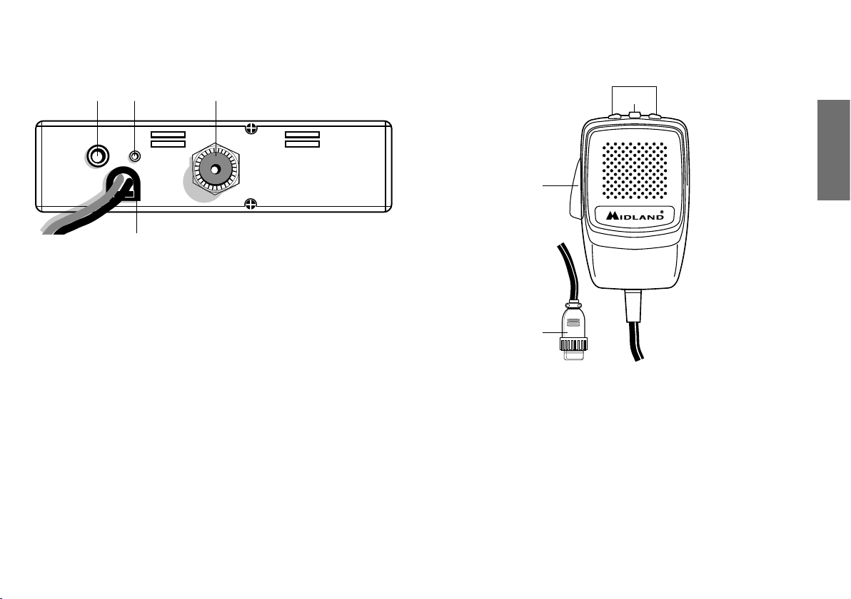
Rear panel
Microphone
13 12 11
EXT
S. METER
ANTENNA
14
11. Antenna connector (SO239 connector type).
12. S. Meter jack: it allows an external “S. Meter” connection.
13. ”EXT” jack: external loudspeaker jack (the internal loudspeaker is
excluded).
14. Power 12.6/24V: power supply cable.
2
3
EN
1
4
1. PTT: transmission button
2. UP/DOWN buttons: manual channel selector
3. LOCK button: it allows you to lock the UP/DOWN buttons.
4. 6 pin microphone connector
3
Page 12

INSTALLATION
Safety and convenience are the primary consideration for mounting any piece of
mobile equipment. All controls must be readily available to the operator without
interfering with the movements necessary for safe operation of the vehicle. Set the
proper position in the car to install the transceiver using the supplied supporting
bracket or eventually the slide bracket. Tighten the retaining screws. The fixing
bracket must be close to metallic parts.
POWER SUPPLY
Be sure the transceiver is OFF. In the direct-voltage power supply, it is very
important to observe the polarity even if the unit is protected against the accidental inversion:
Red = positive pole (+)
Black = negative pole (-)
The same colors are present on the battery and in the fuse box of the car. Correctly
connect the cable terminal to the battery.
ATTENTION: To obtain best performances we recommend to install the radio in
a place with enough air circulation.
INSTALLING AN ANTENNA
1. Place the antenna as high as possible
2. The longer is the antenna, the better will be the performance
3. If possible, mount the antenna in the center of whatever surface you choose
4. Keep antenna cable away from noise sources, such as the ignition switch,
gauges,etc.
5. Make sure you have a solid metal-to-metal ground connection.
6. Prevent cable damage during antenna installation.
WARNING: To avoid damage, never operate your CB radio without connecting a
proper antenna. A periodical control of the cable and of the S.W.R. is recommended.
REPLACING FUSE
If you replace the fuse for DC power Cord, use F 2A 250V type. The parameters
and the symbol of the fuse are indicated in the following label.
F2A 250V +
HOW TO OPERATE WITH YOUR
TRANSCEIVER
1. Screw the microphone plug into the microphone jack.
2. Make sure your antenna is securely connected to the antenna connector.
3. Make sure the SQUELCH control is turned fully counterclockwise.
4. Turn on the unit and adjust the volume control.
5. Select your desired channel.
6. To transmit, press the PTT button and speak in a normal tone of voice.
7. To receive, release the PTT button.
4
Page 13

FREQUENCY BAND SELECTION
The frequency bands must be chosen according to the country where you are
going to operate.
Procedure:
1. Switch off the unit.
2. Turn it on while pushing the “AM/FM” e “SCAN” buttons at the same time.
3. Rotate the “CHANNEL” knob and select the desired frequency band (see
the chart here).
4. To stop your selection, press the “AM/FM” button.
1
: In the UK frequency band, you can select directly the I (Italy) band by
NOTE
pushing the “AM/FM” button for 2 seconds.
2
: If you select a frequency band which operates in FM mode only, the “AM/
NOTE
FM” control enables the LCR function (last channel recall).
FREQUENCY BAND CHART
Digits displayed Country
I Italy 40 CH AM/FM 4Watt
I2 Italy 34 CH AM/FM 4Watt
D4 Germany 80 CH FM 4Watt / 40 CH AM 4Watt
EU Europe 40 CH FM 4Watt / 40 CH AM 1Watt
EC CEPT 40 CH FM 4Watt
E Spain 40 CH AM/FM 4Watt
F France 40 CH FM 4Watt / 40 CH AM 1Watt
PL Poland 40 CH AM/FM 4Watt
UK England 40 CH FM 4 Watt English frequencies
ATTENTION! The frequency band definitely allowed all over Europe is 40 CH FM
4W (EC).
+ I (Italy) 40 CH FM 4Watt CEPT frequencies
TECHNICAL SPECIFICATIONS
GENERAL
Channels ......................................................................(see the frequency band chart)
Frequency Range* ..................................................................26.565-27.99125 MHz
Duty cycle (% on 1 hour) ........................................ TX 5% - RX 5% - Stand-by 90%
Frequency Control ................................................................................................... PLL
Operating Temperature Range ................................................................. -10°/+55° C
DC input voltage ..................................................................................12.6V DC ±10%
Size....................................................................................180 (L)x35 (H)x140 (P) mm
Weight ................................................................................................................0,850 kg
RECEIVER
Receiving system .....................................................dual conversion superheterodyne
Intermediate frequency .....................................I° IF: 10.695 MHz • II° IF: 455 KHz
Sensitivity .........................................................0.5µV for 20 dB SINAD in FM mode
...........................................................................0.5µV for 20 dB SINAD in AM mode
Audio output power @10% THD ..................................................... 2.0 W @ 8 Ohm
Audio distortion ...........................................................................less than 8% @ 1 KHz
Image rejection ........................................................................................................65 dB
Adjacent channel rejection ....................................................................................65 dB
Signal/Noise ratio ................................................................................................... 45 dB
Current drain at stand/by................................................................................... 250mA
TRANSMITTER
Output power ......................................................................................................4W max
Modulation .......................................AM: from 85% to 95% FM: 1,8 KHz ± 0,2 KHz
Frequency response ...............................................................................300 Hz/3 KHz
Output impedance ................................................................ RF 50 Ohm unbalanced
Signal/Noise Ratio ........................................................................................40 dB MIN
Current drain ...................................................................................................... 1100mA
* (covering all approved EU frequency bands)
EN
Specifications are subject to change without notice.
A readily accessible disconnect device shall be incorporated in the installation wiring. The disconnect device shall disconnect both poles simultaneously.
5
Page 14

Page 15

INHALT
BESCHREIBUNG DER BEDIENELEMENTE ............................................................................................................................................................................................ 2
GERÄTERÜCKSEITE .................................................................................................................................................................................................................................3
MIKROFON .................................................................................................................................................................................................................................................3
EINBAU DES ALAN 78 PRO IM KRAFTFAHRZEUG..............................................................................................................................................................................4
ANSCHLUSS AN DIE SPANNUNGSVERSORGUNG ..................................................................................................................................................................4
MONTAGE DER ANTENNE ..................................................................................................................................................................................................................4
SICHERUNG ERSETZEN ........................................................................................................................................................................................................................ 4
BEDIENUNG IHRES ALAN 78 PRO ............................................................................................................................................................................................................4
AUSWAHL DER FREQUENZBÄNDER ......................................................................................................................................................................................................5
FREQUENZTABELLE ............................................................................................................................................................................................................................... 5
D
TECHNISCHE DATEN ...................................................................................................................................................................................................................................... 5
1
Page 16

BESCHREIBUNG DER BEDIENELEMENTE
1 3 5 4 2
109876
1. Kanalwahlschalter: Mit diesem Schalter lassen sich alle 40 Kanäle einstellen.
2. Mikrofonbuchse: Hier wird der Stecker des Mikrofons eingesteckt.
3. MultifunktionsDisplay mit Hintergrund-beleuchtung.
C E H
CH
FMAMSCAN
A
B
LOW
SIG
PWR
NBLOCK EMG DS
RX
TX
KJFI
Die Symbole im Display und deren Beschriftungen können abhängig von der
Produktionscharge abweichen. Im Display werden die folgenden Informationen
angezeigt:
A. Zweistellige Kanalanzeige
B. Relative Empfangsfeldstärke und Sendeleistung
C. AM/FM-Betriebsart. Die Symbole blinken, wenn die Störunterdrückung
(Noise Blanker) aktiviert wurde (hier Version ohne NB und DS)
2
G
D
D. RX-/TX-Anzeige: TX=Sendebetrieb, RX=Empfangsbetrieb.
E. SCAN-Betrieb, Suchlauf nach belegten Kanälen
F. EMG-Kanal, Fernfahrer-/Notruf-Kanal
G. Zeigt das gewählte Frequenzband an.
H. LOW: erscheint, wenn das Funkgerät auf niedrige Ausgangsleistung
schaltet (betrifft nur bestimmte Frequenzbänder – siehe Frequenztabelle)
I. LOCK: Aktivierung der Mikrofon-Tastaturverriegelung (UP/DOWN).
J. NB: Anzeige, dass die Störunterdrückung (Noise Blanker) eingeschaltet
ist (die Funktion kann in der Hauptproduktion abweichen)
K. DS: Anzeige, dass die digitale Rauschsperre eingeschaltet ist (die
Funktion kann in der Hauptproduktion abweichen)
4. Ein/Aus-Schalter, Lautstärkeregler: In der Stellung “OFF” ist Ihr ALAN
78 PRO ausgeschaltet. Durch Drehen des Reglers im Uhrzeigersinn wird
das Gerät eingeschaltet. Weiteres Drehen im Uhrzeigersinn erhöht die
Wiedergabelautstärke nach Wunsch.
5. Rauschsperre: per Drehknopf lässt sich das störende Kanalrauschen eliminieren bzw. auf DS (Digital Squelch) Mode umschalten.
6. Kanal 9 Direkttaste, EMG: Auf Knopfdruck läßt sich der Notrufkanal 9 direkt
einschalten. In der Anzeige erscheint der Schriftzug “EMG”. Ein anderer
Kanal läßt sich nicht einschalten, solange der EMG-Kanal aktiv ist.
7. Kanal-Tasten Q.UP: Drücken der Q.UP-Taste schaltet 10 Kanäle höher.
8. Kanal-Tasten Q.DOWN: Drücken der Q.DOWN Taste schaltet 10 Kanäle
tiefer.
9. Taste “AM/FM”(LCR): Zur Auswahl der gewünschten Betriebsart (AM/FM).
Hält man beim Einschalten die Tasten “AM/FM” und “SCAN” gleichzeitig
gedrückt, kommt man in die Frequenzbandauswahl. Die entsprechende
Wahl wird im Display angezeigt. Wird ein Frequenzband gewählt, das nur
in der Betriebsart FM arbeitet, übernimmt die Taste “AM/FM” statt der
Betriebsartwahl die LCR-Funktion (Last Channel Recall – Aufruf des zuletzt
genutzten Kanals).
10. “SCAN/NB” button: Durch Einschalten des Suchlaufbetriebs lassen sich
belegte Kanäle automatisch suchen. Dazu muß die Rauschsperre so aktiviert
sein, daß das Hintergrundrauschen unterdrückt wird. Drücken der Scan-Taste
startet den Suchlauf. Der Suchlauf stoppt, sobald ein belegter Kanal gefunden
ist. Hält man beim Einschalten die Tasten “AM/FM” und “SCAN” gleichzeitig
gedrückt, kommt man in die Frequenzbandauswahl. Gedrückt halten, um die
Störunterdrückung (Noise Blanker) zu aktivieren.
Page 17

Geräterückseite
Mikrofon
13 12 11
EXT
S. METER
ANTENNA
14
11. Antennenbuchse (SO 239), ANTENNA: Hier wird der Stecker des
Antennenkabels mit dem Funkgerät ver-bunden.
12. S-Meter-Anschluß, S-Meter: An diese Buchse kann ein externes S-Meter
angeschlossen werden.
13. Anschluß für externen Lautsprecher, EXT: An diese Buchse kann ein
externer Wiedergabelautsprecher angeschlossen werden. Der eingebaute
Lautsprecher schaltet sich dann automatisch stumm.
14. Buchse zum Anschluß der Spannungsversorgung, Power 12.6/24Vdc: über
diese Buchse wird das Anschlußkabel mit dem Gerät verbunden.
2
3
1
D
4
1. PTT: Taste zur Sende-/Empfangsumschaltung
2. UP-/DOWN-Tasten: Kanalwahltasten
3. Taste LOCK: Verriegelung der Tasten UP/DOWN am Mikrofon
4. 6-poliger Mikrofonanschluß
3
Page 18

EINBAU DES ALAN 78 PRO
IM KRAFTFAHRZEUG
Einfache Bedienbarkeit ohne Beeinträchtigung der Verkehrssicherheit sollte beim
Fahrzeugeinbau im Vordergrund stehen.
Suchen Sie eine geeignete Einbauposition in Ihrem Fahrzeug und bauen Sie Ihr
ALAN 78 PRO mit Hilfe des Halte-bügels allein oder unter Verwendung der
Führungsschienen ein.
Der Haltebügel sollte möglichst Verbindung mit Metallteilen der Karosserie haben.
WARNUNG!: Um Schäden zu vermeiden, sollten Sie Ihr ALAN 78PLUS MULTI B
niemals ohne geeignete CB-Antenne betreiben. Darüber hinaus empfehlen wir Ihnen,
das Antennenkabel sowie das Stehwellenverhältnis (SWR) in regelmäßigen Abständen
zu überprüfen.
SICHERUNG ERSETZEN
Zum Ersetzen der Sicherung im DC-Kabel verwenden Sie bitte eine 2 A Sicherung
(Typ “F” für 250 V).
ANSCHLUß AN DIE SPANNUNGSVERSORGUNG
Stellen Sie zunächst sicher, daß Ihr ALAN 78 PRO ausgeschaltet ist.
Es ist ganz wichtig, daß Sie den Anschluß des Stromkabels polaritätsrichtig vornehmen.
Dies gilt auch dann, wenn Ihr Gerät gegen mögliche Verpolung geschützt ist:
Rote Kabelader = Pluspol (+)
Schwarze Kabelader = Minuspol (-)
Die gleichen Farben finden Sie an den Batteriepolen und manchmal auch im
Sicherungskasten Ihres Fahrzeugs.
Schließen Sie die Kabelenden besonders sorgfältig an die Stromversorgung des
Fahrzeugs an.
ACHTUNG: Es wird empfohlen, das Gerät an einem Ort mit sehr guter Luftzirkulation
anzubringen.
MONTAGE DER ANTENNE
1. Wählen Sie den Antennenstandort so hoch wie möglich.
2. Je größer die mechanische Länge der Antenne ist, desto besser wird die
Leistung sein.
3. Falls möglich, montieren Sie die Antenne in der Mitte der gewählten
Montagefläche.
4. Verlegen Sie das Antennenkabel möglichst weit entfernt von störenden
Aggregaten (Zündung, elektrischen Verbrauchern usw.).
5. Stellen Sie sicher, daß metallisch leitende Teile des Antennenfußes einen
möglichst großflächigen Kontakt zum metallisch blanken Karosserieblech
haben.
6. Achten Sie darauf, daß das Antennenkabel bei der Montage nicht beschädigt
wird und sich durch Vibrationen im Fahrbetrieb nicht durchscheuern kann.
4
F2A 250V +
BEDIENUNG IHRES ALAN 78 PRO
1. Stecken Sie den Mikrofonstecker in die Mikrofonbuchse Ihres ALAN 78
PRO.
2. Stellen Sie sicher, daß Ihre Funkantenne über das Antennenkabel fest und
sicher mit dem Antennenanschluß Ihres ALAN 78 PRO verbunden ist.
3. Vergewissern Sie sich, daß die Rauschsperre (Squelch) geöffnet ist, d. h. der
Regler bis zum Anschlag gegen den Uhrzeigersinn gedreht ist.
4. Schalten Sie Ihr ALAN 78 PRO ein und stellen Sie die Wiedergabelautstärke
nach Ihren persönlichen Wünschen ein.
5. Stellen Sie den gewünschten Funkkanal ein.
6. Zum Senden drücken Sie die PTT-Taste und besprechen das Mikrofon mit
normaler Lautstärke und Tonlage.
7. Zum Empfangen lassen Sie einfach die PTT-Taste wieder los.
Page 19

Auswahl der Frequenzbänder
Bei der Auswahl der Frequenzbänder sind die Vorschriften der Länder zu beachten,
in denen das Funkgerät betrieben wird.
Vorgehensweise:
1. Schalten Sie das Funkgerät aus.
2. Schalten Sie das Funkgerät wieder ein und halten Sie dabei gleichzeitig die
Tasten „AM/FM“ und „SCAN“ gedrückt.
3. Drehen Sie den Kanalwahlschalter “CHANNEL” und wählen Sie das gewün-
schte Frequenzband aus (siehe Frequenzbandtabelle).
4. Drücken Sie die Taste “AM/FM”, um die Auswahl zu bestätigen.
1
NOTIZ
: Auf dem Frequenzband UK besteht die Möglichkeit das Frequenzband I
(Italien) direkt auszuwählen. Halten Sie dazu die Taste “AM/FM” ca. zwei Sekunden
gedrückt.
2
NOTIZ
: Wird ein Frequenzband gewählt, das nur in der Betriebsart FM arbeitet,
übernimmt die Taste “AM/FM” statt der Betriebsartwahl die LCR-Funktion (Last
Channel Recall – Aufruf des zuletzt genutzten Kanals).
FREQUENZTABELLE
Anzeige im Display Land
I Italien 40 Kanäle AM/FM 4 Watt
I2 Italien 34 Kanäle AM/FM 4 Watt
D4 Deutschland 80 Kanäle FM 4 Watt / 40 Kanäle AM 4 Watt
EU Europa 40 Kanäle FM 4 Watt / 40 Kanäle AM 1 Watt
EC CEPT 40 Kanäle FM 4 Watt
E Spanien 40 Kanäle AM/FM 4 Watt
F Frankreich 40 Kanäle FM 4 Watt / 40 Kanäle AM 1 Watt
PL Polen 40 CH AM/FM 4Watt
UK England 40 Kanäle FM 4 Watt Englische Frequenzen
ACHTUNG: In den meisten europäischen Ländern wird die Standardeinstellung
40 Kanäle FM, 4 W (EC) – akzeptiert. In Deutschland ist für den Betrieb in den
deutschen Programmiereinstellungen d1....d4 (ab Freigabe) als Mobilfunkgerät keine
Anmeldung mehr erforderlich. Einschränkungen gelten für die Kanäle 41 -80 bei
Feststationen in Grenznähe.
+ I (Italien) 40 Kanäle FM 4 Watt CEPT Frequenzen
TECHNISCHE DATEN
ALLGEMEINE DATEN
Kanäle ...................................................................................(siehe die Frequenztabelle)
Frequenzbereich* .....................................................................26.565-27.99125 MHz
Frequenzbelegungsdauer (% pro 1 Stunde) ..........TX 5% - RX 5% - Stand-by 90%
Frequenzerzeugung .....................................................................................PLL-System
Betriebstemperatur ............................................................................... 10° C - +55° C
Spannungsversorgung ...........................................................nom. 12.6 V DC +/- 10%
Abmessungen ...................................................................... 180x35x140 mm (BxHxT)
Gewicht ..............................................................................................................0,850 kg
EMPFÄNGER
Empfangsprinzip .......................................................................................... Doppelsuper
Zwischenfrequenzen .......................................... 1. ZF: 10,695 MHz • 2. ZF: 455 kHz
Empfindlichkeit ................................................................... 0,5 µV bei 20 dB SINAD
NF-Wiedergabeleistung ..................................................... 2 W an 8 Ohm, 10 % Klirr
Wiedergabeverzerrungen ....................................................... weniger als 8% bei 1 kHz
Spiegelfrequenzunterdrückung .............................................................................65 dB
Nachbarkanaldämpfung .........................................................................................65 dB
Geräuschspannungsabstand ................................................................................. 45 dB
Ruhestromaufnahme ......................................................................................... 250 mA
SENDER
Sendeleistung .....................................................................................................4 W max
Modulation ....................................... FM: 1,8 kHz +/-200 Hz AM: von 85% bis 95%
Sendefrequenzgang ................................................................................300 Hz/3 KHz
Ausgangsimpedanz (HF) ..................................................... 50 Ohm, unsymmetrisch
Geräuschspannungsabstand ...................................................................... mind. 40 dB
Stromaufnahme .........................................................................................................1,1 A
* (Abdeckung aller in der EU erlaubten Frequenzbänder)
Abweichungen von den Technischen Daten im Zuge der Weiterentwicklung bleiben vorbehalten.
Direkter Anschluss des Gerätes an DC Netze ist nur über eine entsprechende Sicherung
zulässig.
D
5
Page 20

Page 21

INDICE
FUNCIONES Y SUS CONTROLES .............................................................................................................................................................................................................. 2
PANEL POSTERIOR ................................................................................................................................................................................................................................. 3
MICRÓFONO ............................................................................................................................................................................................................................................ 3
INSTALACIÓN ..................................................................................................................................................................................................................................................... 4
ALIMENTACIÓN ........................................................................................................................................................................................................................................4
INSTALACIÓN DE LA ANTENA ........................................................................................................................................................................................................... 4
CAMBIO DEL FUSIBLE ........................................................................................................................................................................................................................... 4
FUNCIONAMIENTO DEL TRANSCEPTOR ..............................................................................................................................................................................................4
SELECCIÓN DE LA BANDA DE FRECUENCIAS...................................................................................................................................................................................5
TABLA DE BANDAS DISPONIBLES ...................................................................................................................................................................................................5
ESPECIFICACIONES ........................................................................................................................................................................................................................................5
E
1
Page 22

FUNCIONES Y SUS CONTROLES
1 3 5 4 2
109876
1. Selector de canales
2. Toma para el micrófono: Inserte el conector del micrófono.
3. Pantalla retroiluminada multifunción.
C E H
CH
FMAMSCAN
A
B
LOW
SIG
PWR
NBLOCK EMG DS
RX
TX
KJFI
Los iconos de la pantalla y su descripción pueden variar según el lote de pro-
ducción. Muestra:
A. El número del canal seleccionado
B. Intensidad de la señal recibida y la potencia de la señal transmitida.
C. Modo AM/FM. Estos iconos parpadean si se ha activado la función
NOISE BLANKER (se muestra la versión sin NB ni DS).
2
G
D
D. RX/TX: TX = modo de transmisión; RX = modo de recepción.
E. Modo de exploración (SCAN)
F. Modo de emergencia (EMG)
G. tabla de bandas disponibles
H. LOW: se visualiza cuando la radio transmite con baja potencia (condición
que se da sólo en determinadas bandas de frecuencia – véase tabla de
bandas)
I. LOCK: teclado (UP/DOWN) del micrófono bloqueado
J. NB: indicador del filtro Noise Blanker habilitado (esta función puede ser
diferente, dependiendo del lote de producción).
K. DS: indicador de Digital Squelch activado (esta función puede ser dife-
rente, dependiendo del lote de producción).
4. Control ON/OFF Volume (encendido y volumen): En la posición OFF el
transceptor está apagado. Gire este control hacia la derecha para encender
la unidad. Continúe girándolo poco a poco hacia la derecha hasta alcanzar el
nivel de audio deseado.
5. Control SQUELCH (silenciador): este mando permite eliminar el ruido de
fondo del receptor no deseado y operar en modo DS (Squelch Digital).
6. Botón EMG: Canal de emergencia. Pulse este botón para posicionarse
automáticamente en el CH 9 (canal de emergencia). La pantalla muestra
“EMG”. Con esta función activada, el selector de canales queda inhabilitado.
7. Boton Q.UP: Para saltar rápidamente 10 canales hacia arriba.
8. Boton Q.DOWN: Para saltar rápidamente 10 canales hacia abajo.
9. Botón AM/FM (LCR): Sirve para seleccionar el tipo de modulación deseada:
AM o FM. Si mientras se enciende el equipo se pulsa juntamente con la
tecla “SCAN”, selecciona la banda operativa. La selección se visualizará en el
display. Si selecciona una banda de frecuencia que opera sólo en modo FM, la
tecla “AM/FM” activa la función LCR (llamada del último canal seleccionado)
10. Botón SCAN/NB (exploración): Con esta función activada el equipo busca
automáticamente los canales ocupados. Gire hacia la derecha el botón
del silenciador (SQUELCH) hasta que desaparezca el ruido de fondo.
Pulse el botón SCAN: el transceptor efectuará la exploración automática de todos los canales hasta que en alguno de ellos encuentre una señal.
Si mientras se enciende el equipo se pulsa juntamente con la tecla “AM/
FM”, selecciona la banda operativa. La selección se visualizará en el display.
Mantenga pulsado para activar el Noise Blanker.
Page 23

Panel posterior
Micrófono
13 12 11
EXT
S. METER
ANTENNA
14
11. Conector de antena: (Conector tipo SO239).
12. Jack S.Meter: Permite la conexión de un medidor de señal externo.
13. Jack EXT: para la conexión de un altavoz externo (opcional); al conectar el
altavoz externo, el interno queda desactivado.
14. Power 12.6/24Vcc: Entrada de alimentación.
2
3
1
4
E
1. PTT: botón de transmisión
2. Pulsadores UP/DOWN: Selector manual de canales.
3. Tecla LOCK: permite bloquear los pulsadores UP/DOWN del micrófono
4. Conector del micrófono de 6 pines
3
Page 24

INSTALACIÓN
La seguridad y la facilidad son las consideraciones primordiales para efectuar el
montaje de cualquier equipo móvil. Todos los controles deben ser fácilmente
accesible al operador, sin que ello interfiera en la correcta conducción del vehículo.
Seleccione la posición adecuada del vehículo donde instalar el transceptor y use el
soporte suministrado o eventualmente un soporte deslizante (opcional). Coloque
los tornillos de retención. El soporte de fijación debe estar en contacto con las
partes metálicas.
Atención: le recordamos que está totalmente prohibido utilizar micrófonos de mano
en las comunicaciones móviles (en vehículos). Existe a su dispoción un “kit manos
libres” original MIDLAND que le permitirá utilizar la radio sin necesidad de apartar
las manos del volante, manteniendo las prestaciones del equipo y aumentando considerablemente tanto su seguridad como la del resto de conductores.
ALIMENTACIÓN
Asegúrese de que el transceptor está apagado. En la alimentación de corriente
continua es muy importante observar la polaridad incluso si la unidad está protegida
contra una inversión accidental:
Rojo = polo positivo (+); Negro = polo negativo (-)
Los mismos colores se encuentran presentes en la batería y en la caja de fusibles del
vehículo. Conecte correctamente el terminal del cable a la batería.
INSTALACIÓN DE LA ANTENA
1. Instale la antena lo más alta posible.
2. Cuanto más larga sea la antena, mejores prestaciones obtendrá.
3. Si es posible, monte la antena en el centro de la superficie escogida.
4. Mantenga el cable de antena a resguardo de fuentes de ruido, tales como el
encendido del coche, etc.
5. Asegúrese de que dispone de una sólida conexión a masa metal a metal.
6. Evite que se dañe el cable durante la instalación de la antena.
Advertencia: Para evitar provocar daños, nunca opere su radio sin que esté conectada
a una antena adecuada. Se recomienda un control periódico del cable y de las ROE.
CAMBIO DEL FUSIBLE
Si debe cambiar el fusible del cable de alimentación, utilice uno del tipo F 2A
250V. Los parámetros y el símbolo del fusible se indican en la siguiente etiqueta:
F2A 250V +
FUNCIONAMIENTO DEL TRANSCEPTOR
1. Enchufe el micrófono en el jack correspondiente.
2. Asegúrese de que la antena esté conectada al equipo.
3. Verifique que el control del silenciador esté girado completamente hacia la
izquierda.
4. Encienda la unidad y ajuste el control de volumen.
5. Seleccione el canal deseado.
6. En ausencia de señal, ajúste el silenciador (squelch) para eliminar el ruído de
fondo.
7. Para transmitir, pulse el botón PTT y hable a unos 10cm del micrófono y con
un tono de voz normal.
8. Para recibir, libere el botón PTT.
4
Page 25

SELECCIÓN DE LA BANDA
DE FRECUENCIAS
La selección de la banda de frecuencias debe ser acorde al país de uso del equipo.
Procedimiento:
1. Apague el equipo
2. Enciéndalo mientras pulsa las teclas “AM/FM” y “SCAN”
3. Seleccione la banda deseada girando el mando “CHANNEL” (consulte la tabla
de las bandas disponibles).
4. Pulse la tecla “AM/FM” para confirmar la selección
1
NOTA
: en la banda de frecuencia UK se puede seleccionar directamente la banda I
(Italia) pulsando la tecla “AM/FM” durante 2 segundos
2
NOTA
: si selecciona una banda de frecuencia que opera sólo en modo FM, la tecla
“AM/FM” activa la función LCR (llamada del último canal seleccionado)
TABLA DE BANDAS DISPONIBLES
Sigla en el display País
I Italia 40 CH AM/FM 4W
I2 Italia 34 CH AM/FM 4W
D4 Alemania 80 CH FM 4W / 40 CH AM 4W
EU Europa 40 CH FM 4W / 40 CH AM 1W
EC CEPT 40 CH FM 4W
E España 40 CH AM/FM 4W
F Francia 40 CH FM 4W / 40 CH AM 1W
PL Polonia 40 CH AM/FM 4W
UK Reino Unido 40 CH FM 4W frecuencias UK
¡ATENCIÓN! El estándar reconocido en todos los países europeos es 40CH FM 4W
(EC) - vea la tabla “Restricciones al uso”
+ I (Italia) 40 CH CEPT FM 4W
ESPECIFICACIONES
GENERALES
Canales ..........................................................................................................(ver la tabla)
Rango de frecuencias ................................................................. 26.965-27.405 MHz
Ciclo de trabajo (% en 1 hora).................................TX 5% - RX 5% - Stand-by 90%
Control de frecuencia ............................................................................................... PLL
Gama de temperaturas de operación .................................................-10 ºC a +55 ºC
Tensión CC de entrada ..........................................................................12.6 Vcc ± 10%
Tamaño ......................................................................................................180 x 35 x 140 mm
Peso ............................................................................................................................0.850 Kg
RECEPTOR
Sistema de recepción ..................................................... Conversión dual superheterodina
Frecuencia intermedia ..................................................................Primera FI: 10.695 MHz
................................................................................................................Segunda FI: 455 KHz
Sensibilidad ............................................................0.5 µV @ 20 dB SINAD en modo FM
.................................................................................0.5 µV @ 20 dB SINAD en modo AM
Potencia de salida de audio a 10% THD .............................................2.0 W @ 8 Ohmios
Distorsión de audio ...........................................................................Menos de 8% @ 1 KHz
Rechazo de imagen .........................................................................................................65 dB
Rechazo del canal adyacente ........................................................................................ 65 dB
Relación señal/ruido .......................................................................................................45 dB
Consumo en espera....................................................................................................250 mA
TRANSMISOR
Potencia de salida ........................................................................................................4W max
Modulación .........................................AM: desde 85% a 95% - FM: 1.8 KHz ± 0.2 KHz
Respuesta de frecuencia...............................................................................300 Hz/3 KHz
Impedancia de salida ...................................................RF 50 Ohmios no balanceados
Relación señal/ruido ................................................................................40 dB mínimo
Consumo ........................................................................................................... 1100 mA
E
Todas las especificaciones están sujetas a cambio sin previo aviso.
El cable de alimentación incorpora un dispositivo de fácil desconexión.
Dicho dispositivo desconecta los dos polos simultáneamente.
5
Page 26

Page 27

SOMMAIRE
FONCTION ET EMPLACEMENT DES COMMANDES ......................................................................................................................................................................... 2
PANNEAU ARRIERE ................................................................................................................................................................................................................................ 3
MICROPHONE .......................................................................................................................................................................................................................................... 3
INSTALLATION ....................................................................................................................................................................................................................................................4
ALIMENTATION ......................................................................................................................................................................................................................................... 4
INSTALLATION DE L’ANTENNE .......................................................................................................................................................................................................... 4
REMPLACEMENT DU FUSIBLE ...........................................................................................................................................................................................................4
UTILISATION DE L’ALAN 78 PRO ................................................................................................................................................................................................................4
SELECTION DES BANDES DE FREQUENCE ......................................................................................................................................................................................... 5
TABLEAU DES BANDES DE FREQUENCE ..................................................................................................................................................................................... 5
SPECIFICATIONS TECHNIQUES ................................................................................................................................................................................................................5
F
1
Page 28

FONCTION ET EMPLACEMENT
DES COMMANDES
1 3 5 4 2
109876
1.
2. Selection des canaux.
3. Embase de raccordement du microphone.
4. Écran multifonctions
C E H
CH
FMAMSCAN
A
B
LOW
SIG
PWR
NBLOCK EMG DS
RX
TX
KJFI
Les icônes à l’écran et leur description peuvent varier en fonction du lot de
production.
A. Canaux sélectionnés
B. Niveau du signal reçu et niveau de puissance émise.
C. Mode AM ou FM. Ces icônes clignotent si la fonction NOISE BLANKER
a été activée (version sans NB et DS affiché).
D. RX: Réception. TX : Emission.
2
G
D
E. SCAN: mode de balayage.
F. EMG: mode de canal de sécurité (9).
G. Indique la bande de fréquence sélectionnée.
H. LOW: est visualisé quand la radio transmet en basse puissance (cette
condition se vérifie seulement pour certaines bandes de fréquence – voir
le tableau des bandes de fréquence).
I. LOCK: Blocage du clavier du microphone (UP/DOWN) activé.
J. NB: indicateur de l’activation du filtre anti-bruit (cette fonctionnalité
peut différer en fonction du lot de production).
K. DS: indicateur du Squelch Digital activé (cette fonctionnalité peut
différer en fonction du lot de production).
4. Arrêt/Marche et contrôle volume: OFF: appareil éteint, VOLUME: permet
le réglage du niveau d’écoute.
5. Contrôle du silencieux DS/SQ: ce bouton permet d’éliminer le bruit de fond
indésirable du récepteur et de fonctionner en mode DS (Digital Squelch).
6. EMG. Canal d’Urgence: Sélectionne le canal 9. Pour changer le canal suppri-
mer la fonction « EMG».
7. Q.UP: Permet de sélectionner 10 canaux avant.
8. Q.DOWN: Permet de sélectionner 10 canaux arrière.
9. Bouton “AM/FM” (LCR): Pour sélectionner le mode AM ou FM. Si vous
l’appuyez avec le bouton “SCAN” quand vous allumez l’émetteur, “AM/FM”
sélectionne la bande operative. Votre choix sera visualisée sur l’écran. Quand
vous sèlectionnez une bande de fréquence seulement en modalité FM, la
touche active la fonction LCR (rappeler le dernier canal utilisè).
10. Bouton “SCAN/NB”: la fonction SCAN (balayage des canaux) est uti-
lisé pour vérifier le trafic radio sur les canaux avant de choisir un canal
pour émettre. NOTE: Il est impératif que le bouton de Squelch ou silencieux soit lentement tourné dans le sens horaire à la limite ou le bruit
disparaît du haut parleur en l’absence de réception utile. Si vous l’appuyez avec le bouton “AM/FM”, quand vous allumez l’émetteur, “SCAN”
sélectionne la bande operative. Votre choix sera visualisée sur l’écran.
Maintenez appuyé pour activer le Noise Blanker.
Page 29

Panneau arriere
Microphone
13 12 11
EXT
S. METER
ANTENNA
14
11. Connecteur antenne (modèle S0239).
12. Connecteur pour un «S METRE» externe. (Indicateur de niveau).
13. Raccordement pour un haut parleur externe en mode CB (Dans ce cas le haut
parleur interne est stoppé).
14. Cordon d’alimentation 12.6/24Vcc.
2
3
1
4
1. PTT: bouton pour l’émission.
2. UP/DOWN: boutons de changement de canal.
3. LOCK: permet le blocage des touches UP/DOWN du microphone.
4. Fiche de raccordement du microphone.
F
3
Page 30

INSTALLATION
Sécurité et montage aisé doivent guider toute l’installation. Tous les contrôles
doivent être accessibles à l’opérateur sans provoquer de mouvements pouvant
mettre en danger le conduite du véhicule. Sélectionner la meilleure position pour
l’équipement afin d’allier discrétion et sécurité. Utiliser l’étrier de montage livré
avec l’équipement. Bien fixer l’équipement.
ALIMENTATION
S’assurer que l’appareil est arrêté (position OFF).
Vérifier la polarité du câble d’alimentation :
• Le fil rouge doit être relié à la borne positive +
• Le fil noir doit être relié à la borne négative -.
Les dégâts éventuels provoqués par un mauvais câblage ne sont pas couverts par
la garantie.
ATTENTION: Pour obtenir de meilleures performances, il est recommandé d’installer
la radio où l’air est bien recyclé.
INSTALLATION DE L’ANTENNE
Le rendement de votre installation est totalement lié à la qualité de l’antenne
utilisée.
Respecter les règles suivantes:
1. Placer l’antenne le plus haut possible.
2. La longueur de l’antenne doit être la plus importante possible.
3. Si possible centrer l’antenne sur une surface métallique plane.
4. Eloigner le plus possible le câble de l’antenne des sources d’interférences du
véhicule (alternateur, bobines, calculateurs, etc.)
5. Assurer un excellent contact de la masse de votre antenne avec la masse du
véhicule.
6. Contrôler soigneusement le passage du câble d’antenne. Eviter les courbures
trop raides qui pourraient le blesser.
ATTENTION: il est recommandé de contrôler régulièrement la qualité de votre installation d’antenne si possible à l’aide d’un Wattmètre TOS mètre.
REMPLACEMENT DU FUSIBLE
Remplacer le fusible du câble d’alimentation avec un similaire du type F 2A 250V.
Les paramètres et le symbole du fusible sont indiqués dans cette étiquette.
F2A 250V +
UTILISATION DE L’ALAN 78 PRO
Une fois l’installation réalisée :
1. Connecter votre microphone,
2. Régler le silencieux (Squelch),
3. Règler l’appareil et régler le volume en position médiane,
4. Sélectionner le canal désiré,
5. Pour émettre appuyer sur le PTT du micro et parler normalement à 10 cm
du micro.
6. Pour écouter, relâcher le PTT.
4
Page 31

SELECTION DES BANDES
DE FREQUENCE
Les bandes de fréquence doivent être choisies selon le pays ou vous voulez opérer.
1. Eteignez l’appareil.
2. Allumez la radio et appuyez dans le même temps les touches “AM/FM” et
“SCAN”.
3. Avec le commande “CHANNEL”, sélectionnez la bande de fréquence désirée
(voir le tableau des bandes de fréquence).
4. Appuyez le bouton “AM/FM” pour terminer la sélection.
1
NOTE
: Dans la bande de fréquence UK, c’est possible de sélectionner directement la
bande I (Italie) en appuyant la touche “AM/FM” pour 2 secondes environ.
2
NOTE
:Quand vous sélectionnez une bande de fréquence seulement en modalité FM,
la touche “AM/FM” active la fonction LCR (rappeler le dernier canal utilisé).
TABLEAU DES BANDES DE FREQUENCE
Sigle sur l’écran Pays
I Italie 40 CH AM/FM 4Watt
I2 Italie 34 CH AM/FM 4Watt
D4 Allemagne 80 CH FM 4Watt / 40 CH AM 4Watt
EU Europe 40 CH FM 4Watt / 40 CH AM 1Watt
EC CEPT 40 CH FM 4Watt
E Espagne 40 CH AM/FM 4Watt
F France 40 CH FM 4Watt / 40 CH AM 1Watt
PL Pologne 40 CH AM/FM 4Watt
UK Angleterre 40 CH FM 4 Watt fréquences anglaises + I
ATTENTION! La bande de fréquences reconnue sûrement dans tous les pays
européens est 40CH FM 4W (EC) - voir le tableau pour les réstrictions à l’usage.
(Italie) 40 CH FM 4Watt fréquences CEPT
SPECIFICATIONS TECHNIQUES
GENERALITES
Canaux .......................................................(voir le tableau des bandes de fréquences)
Bande de fréquence* ................................................................26.565-27.99125 Mhz
Cicle d’usage (% dans 1 heure) ............................... TX 5% - RX 5% - Stand-by 90%
Générateur de fréquence .................................................................... par synthétiseur
Température d’utilisation ............................................................................-1O°/+55°C
Tension d’alimentation .....................................................................12.6 V DC+/- 10 %
Dimensions ...................................................................................... 180 x 35 x 140 mm
Poids ...................................................................................................................0,850 kg
RECEPTEUR
Système de réception ......................................Superhétérodyne à double conversion
Fréquence intermédiaire ................................................1er 10,695 Mhz. 2è 455 Khz
Sensibilité ......................................................... 0,5 µv pour 20 dB SINAD AM et FM
Puissance audio ..................................................................................... 2 W @ 8 Ohms
Distorsion ..................................................................................Mieux que 8 % @ 1 Khz
Réjection image ......................................................................................................65 dB
Réjection canal adjacent .........................................................................................65dB
Consommation................................................................................................... 250 mA
EMETTEUR
Puissance ............................................................................................................4 W max
Modulation .................................................................................FM 1,8 KHz ± 0,2 KHz
.......................................................................................................... AM de 85 % à 95 %
Bande audio .............................................................................................300 Hz/3 KHz
Impédance antenne ......................................................................................... 50 Ohms
Consommation.....................................................................................................1,100 A
F
* (conformément à toutes les bandes de fréquence européennes approuvées)
Toutes ces caractéristiques peuvent être modifié sans préavis.
Il est conseillé de mettre un interrupteur dans le câblage d’alimentation du poste. L’interrupteur
doit couper les deux pôles simultanément.
5
Page 32

Page 33

SPIS TRESCI
FUNKCJE I ROZMIESZCZENIE ELEMENTOW STEROWANIA ......................................................................................................................................................... 2
PANEL TYLNY .............................................................................................................................................................................................................................................3
MIKROFONOWE ...................................................................................................................................................................................................................................... 3
INSTALACJA ........................................................................................................................................................................................................................................................4
ZASILANIE ................................................................................................................................................................................................................................................... 4
INSTALOWANIE ANTENY ...................................................................................................................................................................................................................... 4
WYMIANA BEZPIECZNIKA .................................................................................................................................................................................................................... 4
UZYTKOWANIE RADIOTELEFONU ............................................................................................................................................................................................................4
WYBIERANIE PRZEDZIALU CZESTOTLIWOSCI ..................................................................................................................................................................................... 5
TABELA CZESTOTLIWOSCI ...................................................................................................................................................................................................................5
DANE TECHNICZNE ........................................................................................................................................................................................................................................ 5
1
POL
Page 34

FUNKCJE I ROZMIESZCZENIE
ELEMENTOW STEROWANIA
1 3 5 4 2
109876
1.
2. Przelacznik kanalow
3. Gniazdo mikrofonowe: tu nalezy podlaczyc wtyk mikrofonu
4. Wielofunkcyjny wyswietlacz
C E H
CH
FMAMSCAN
A
B
LOW
SIG
PWR
NBLOCK EMG DS
RX
TX
KJFI
Wyświetlane ikony i ich znaczenie mogą się różnić w zależności wersji.
A. Numer aktualnie uzywanego kanalu
B. Poziom odbieranego i wysylanego sygnalu
C. AM/FM rodzaj emisji. Ikona miga gdy funkcja NOISE BLANKER jest
aktywna (wersja bez wyświetlanego NB i DS).
D. RX/TX stan nadawanie / odbior.
E. SCAN sygnalizuje dzialanie skanera
2
G
D
F. EMG pokazuje status kanalow uznanych powszechnie za ratunkowe
G. Wybrany zakres czestotliwosci
H. LOW informuje o nadawaniu z mala moca (funkcja dostepna w niektorych
zakresach czestotliwosci – patrz Tabela Czestotliwosci)
I. LOCK zablokowana mozliwosc przelaczania kanalow w mikrofonie.
J. NB: wskaźnik włączenia filtra Noise Blanker (ta funkcja może się rożnić w
zależności od wersji).
K. DS: wskaźnik włączenia filtra Cyfrowej Automatycznej Blokady Szumów
(ta funkcja może się rożnić w zależności od wersji)
4. ON/OFF VOL pokretlo wlacza/wylacza radiotelefon i reguluje sile glosu.
W pozycji OFF urzadzenie jest wylaczone. Przekrecanie zgodnie z ruchem
wskazowek zegara powoduje najpierw wlaczenie radiotelefonu a potem wzrost
poziomu odsluchiwanych w glosniku dzwiekow.
5. DS/SQ Pokrętło blokady szumów: pokrętło pozwala wyeliminować szumy tła i
korzystać z Cyfrowej Automatycznej Blokady Szumów DS.
6. EMG przycisk pozwala szybko przelaczyc radiotelefon na kanal 9. Przypadkowa
zmiana kanalu nie bedzie mozliwa.
7. Q. UP przyciski pozwalaja na zmiane kanalow co 10 w gore lub.
8. Q. DOWN przyciski pozwalaja na zmiane kanalow co 10 w gore dol.
9. AM/FM przelacznik sluzy do wyboru rodzaju emisji w modulacji amplitudy AM
lub czestotliwosci FM.
10. SCAN/NB przelacznik umozliwia szybkie przegladanie kanalow w poszukiwaniu
aktywnosci radiowej. Aby skorzystac z tej funkcji:
a) przekrecaj pokretlo blokady szumow zgodnie z ruchem wskazowek zegara
az do
b) momentu gdy szumy tla stana sie nieslyszalne.
c) acisnij przycisk SCAN; na wyswietlaczu pojawi sie znak SCAN.
Skaner zatrzyma sie gdy znajdzie sygnal mocniejszy od poziomu blokady
szumow. Funkcje wylacza sie tym samym przyciskiem lub zmieniajac kanal
albo wciskajac nadawanie. Przytrzymaj wciśnięty, aby włączyć funkcję redukcji
szumów.
Page 35

PANEL TYLNY
MIKROFONOWE
13 12 11
EXT
S. METER
ANTENNA
14
11. Gniazdo antenowe ( z_acze SO239 ).
12. Gniazdo miernika sygnalu - pozwala podlaczyc zewnetrzny miernik.
13. Gniazdo EXT zewnetrznego glosnika ( wlozenie wtyku automatycznie wylacza
wbudowany glosnik wewnetrzny ).
14. Kabel zasilajacy 12.6/24Vdc.
2
3
1
4
1. PTT przycisk wlaczajacy nadawanie.
2. UP/DOWN przyciski zmiany kanalow.
3. LOCK przycisk blokujacy dzialanie sasiednich, sluzacych do zmiany kanalow.
4. Wtyk mikrofonowy 6-pin.
3
POL
Page 36

INSTALACJA
Przed przystapieniem do montazu radiotelefonu w samochodzie nalezy starannie
wybrac najlepsze dla niego miejsce. Dostep do elementow sterujacych powinien
byc swobodny, a manipulacja nimi nie moze utrudniac prowadzenia pojazdu. Do
zamontowania moze posluzyc obejma bedaca w komplecie albo odpowiednia
kieszen, pozwalajaca na szybkie wyjmowanie urzadzenia. Obejma lub kieszen
powinna byc mocowana blisko metalowych czesci samochodu. Wszystkie sruby, z
dwoma mocujacymi radio wlacznie, musza byc mocno dokrecone.
wymiana bezpiecznika
Jeżeli wymieniasz bezpiecznik na przewodzie zasilajacym, uzyj bezpiecznika F 2A
250V. Parametry i symbol bezpiecznika uwidocznione sa na naklejce.
F2A 250V +
ZASILANIE
Przed podlaczeniem zasilania upewnij sie, ze radiotelefon jest wylaczony ( pokretlo
w pozycji OFF ). Zasilanie pradem stalym wymaga bacznego zwrocenia uwagi na
polaryzacje nawet jesli urzadzenie posiada odpowiednie zabezpieczenia.
Czerwony - biegun dodatni ( + ).
Czarny - biegun ujemny ( - ).
Tych samych kolorow uzyto na akumulatorze i w skrzynce bezpiecznikow w samochodzie dla oznaczenia polaryzacji. Lacz ze soba tylko kable w tym samym kolorze.
UWAGA: Zaleca sie zamontowanie radia w miejscu zapewniajacym jak najlepsza
wentylacje.
INSTALOWANIE ANTENY
1. Montuj antene zawsze w mozliwie najwyzszym punkcie.
2. Dluzsza antena zapewnia z reguly dalsza lacznosc.
3. Montuj antene dokladnie w centrum wybranej powierzchni.
4. Prowadz kabel antenowy z dala od zrodel zaklocen takich jak aparaty zaplonowe
itp.
5. Upewnij sie, ze oplot kabla ( masa ) jest polaczony z metalowymi czesciami
nadwozia.
6. Podczas instalacji chron kabel przed uszkodzeniem.
UWAGA:Aby uniknac zniszczenia radiotelefonu ( tranzystora mocy ) nigdy nie uzywaj
go bez wlasciwie podlaczonej, dobrze zestrojonej anteny. Zaleca sie okresowe ogledziny
kabla i sprawdzenie wartosci Wspolczynnika Fali Stojacej ( SWR ).
4
UZYTKOWANIE RADIOTELEFONU
1. Podlacz mikrofon do gniazda w przednim panelu.
2. Upewnij sie, ze antena jest podlaczona wlasciwie i dobrze zestrojona.
3. Sprawdz, czy pokretlo blokady szumow SQUELCH znajduje sie w skrajnym,
lewym polozeniu.
4. Wlacz radiotelefon i ustaw odpowiedni dla siebie poziom glosnosci.
5. Wybierz kanal na ktorym chcesz nawiazac lacznosc.
6. Chcac nadawac trzymaj wcisniety przycisk PTT i mow w normalny sposob.
7. Zwalniajac przycisk PTT przelaczasz radiotelefon na odbior.
Page 37

WYBIERANIE PRZEDZIALU
CZESTOTLIWOSCI
Przedzial czestotliwosci jest wybrany przez importera radiotelefonow zgodnie z
prawem obowiazujacym na terenie wprowadzania ich do obrotu.
Ponizej wyszczegolniono rozne ustawienia stosowane w krajach Europy.
1
Uwaga
: Jezeli wybierzesz standard dopuszczjacy prace tylko w modulacji FM
przycisk zmiany emisji AM/FM pelni funkcje przywolania ostatnio uzywanego kanalu.
TABELA CZESTOTLIWOSCI
WYSWIETLANE
OZNACZNIE
I Wlochy 40 kanalow AM/FM, 4 W
I2 Wlochy 34 kanaly AM/FM, 4 W
D4 Niemcy 80 kanalow FM, 4 W/40 kanalow AM, 4W
EU Europa 40 kanalow FM, 4 W/40 kanalow AM, 1 W
EC CEPT 40 kanalow FM, 4 W
E Hiszpania 40 kanalow AM/FM, 4 W
F Francja 40 kanalow FM, 4 W/40 kanalow AM, 1 W
PL Polska 40 kanalow AM/FM, 4 W, "0"
PX Polska czterystukanalowa AM/FM, 4 W, "0"
RU Rosja czterystukanalowa AM/FM, 4 W
SW Szwecja 24 kanaly FM, 4 W, 31 MHz
UK Wielka Brytania 40 kanalow FM, 4 W, angielski zakres
Uwaga! 40ch AM/FM 4W (czestotliwosci polskie) - dostepne tylko w urzadzeniach
sprzedawanych w Polsce.
Wersja czterystukanalowa dostepna na rynki zagraniczne.
KRAJ, ZAKRES
+ I (Wlochy) 40 kanalow FM, 4 W
DANE TECHNICZNE
OGOLNE
Ilosc kanalow ...............................................................................................(Patrz tabela)
Zakres czestotliwosci* ...........................26.960-27.400 (26.565 - 27.99125) MHz
Cykl pracy (% na 1 godzine) ...................................TX 5% - RX 5% - Stand-by 90%
Kontrola czestotliwosci ........................................................................Petla fazowa PLL
Temperatura pracy ........................................................................................-10/+55 °C
Zasilanie .....................................................................................12.6 V prad staly ± 10 %
Wymiary zewnetrzne .......................................................................... 180x35x140 mm
Waga .......................................................................................................................0,85kg
ODBIORNIK
System odbioru .................... superheterodyna z podwojna przemiana czestotliwosci
Czestotliwosci posrednie ..........................................................10.695 MHz i 455 kHz
Czulosc .............................................................0,5 µV przy 20dB SINAD w AM/FM
Moc wyjsciowa audio ....................................................................................2,0 W, 8 W
Znieksztalcenia akustyczne .................................................................. < 8 % przy 1 kHz
Tlumienie czestotliwosci lustrzanej........................................................................65 dB
Separacja kanalow ...................................................................................................65 dB
Odstep sygnal/szum .............................................................................................. 45 dB
Pobor pradu przy odbiorze ................................................................................ 250 mA
NADAJNIK
Moc wyjsciowa ...................................................................................................4 W max
Mudulacja ..............................................FM: 1.8 kHz ± 0.2 kHz - AM: 85% do 95%
Pasmo przenoszenia ................................................................................300 Hz/3 KHz
Impedancja wyjsciowa .............................................................................................50 W
Odstep sygnal/szum ...................................................................................... min 40 dB
Pobor pradu ........................................................................................................ 1100mA
* (pokrywa wszystkie legalne pasma w UE)
Dane mogą ulec zmianie bez uprzedzenia.
W okablowaniu należy umieścić urządzenie pozwalające na natychmiastowe odłączenie radiostacji. Urządzenie odłączające powinno równocześnie odłączać oba bieguny.
5
POL
Page 38

6
Page 39

INDEX
INDEX ...................................................................................................................................................................................................................................................................... 1
DESCRIERE TASTE SI FUNCTII .....................................................................................................................................................................................................................2
PANOUL POSTERIOR ......................................................................................................................................................................................................................................3
MICROFON ......................................................................................................................................................................................................................................................... 3
INSTALARE ........................................................................................................................................................................................................................................................... 4
ALIMENTARE .......................................................................................................................................................................................................................................................4
INSTALAREA UNEI ANTENE ......................................................................................................................................................................................................................... 4
INLOCUIREA SIGURANTEI ............................................................................................................................................................................................................................4
INSTRUCTIUNI DE UTILIZARE ...................................................................................................................................................................................................................... 4
SELECTAREA BENZII DE FRECVENTE .....................................................................................................................................................................................................5
RO
TABEL FRECVENTE ..........................................................................................................................................................................................................................................5
SPECIFICATII TEHNICE ................................................................................................................................................................................................................................... 5
1
Page 40

DESCRIERE TASTE SI FUNCTII
1 3 5 4 2
1. Selector canale
2. Mufa microfon: Introduceti microfonul in aceasta mufa.
3. Ecran retroiluminat multifunctional.
A
B
Tastele si functiile lor
A. Numar canal selectionat
B. Indicator semnal receptionat si putere semnal transmis
C. Mod AM/FM.
pot varia in functie de lotul de productie.
Aceste pictograme clipesc daca functia NOISE
BLANKER este activa (versiunea fara NB si DS afisate pe ecran).
109876
C E H
CH
FMAMSCAN
LOW
SIG
PWR
NBLOCK EMG DS
KJFI
RX
TX
D. RX/TX: TX=
E. SCAN indicator functie SCAN activa
F. EMG indicator functie canal de urgenta activa
G. Banda de frecvente selectata.
H. LOW: vine vizualizat cand statia transmite cu putere joasa (conditie
transmisie; RX=receptie.
care se verifica doar pentru anumite benzi de frecventa – vezi tabelul
cu frecvente
I. LOCK: taste blocate pe microfon (tastele UP/DOWN) .
J. NB: filtru Noise Blanker activat (aceasta functie poate diferi in functie
de lotul de productie)
K. DS: indicator Digital Squelch activ (aceasta functie poate diferi in functie
de lotul de productie).
4. Butonul “ON/OFF Volume”: pe pozitia ‘’off’’ statia este oprita. Rotiti butonul
in sensul acelor de ceasornic pentru a porni statia. Continuati sa rotiti spre
dreapta pentru a regla volumul, pana obtineti nivelul dorit.
5. Butonul “DS/SQ”: acest buton permite eliminarea zgomotului de fundal pe
receptie si operarea in modul DS (Digital Squelch).
6. Butonul EMG: Canal de urgenta. Apasand aceasta tasta, statia va trece
automat pe CH 9 (canal de urgenta). Pe ecran va aparea “EMG”. Nu se va
putea schimba canalul in mod accidental.
7. Butonul “Q. UP”: Pentru a sari rapid peste 10 canale in sus (Q. UP).
8. Butonul “Q. DOWN”: Pentru a sari rapid peste 10 canale in jos (Q. DOWN).
9. Tasta “AM/FM” (LCR) : Pentru a selecta modul AM sau FM. Daca apasati
G
D
aceasta tasta impreuna cu tasta “SCAN” in timp ce porniti statia, puteti
schimba banda, care va fi afisata pe ecran. Daca se selecteaza o banda de
frecvente care opereaza doar in FM, tasta AM/FM activeaza functia LCR
(Last Channel Recall).
10. Tasta “SCAN/NB”: cu aceasta tasta se poate cauta automat un canal ocupat.
Rotiti butonul Squelch in sensul acelor de ceasornic pana nu mai auziti zgomotul de
fundal. Apasati tasta ‘’SCAN’: statia va scana automat toate canalele pana cand
va gasi un canal ocupat. Daca in timp ce se porneste statia se apasa aceasta tasta
impreuna cu tasta “AM/FM”, puteti selecta banda, care va fi afisata pe ecran.
Tineti apasat acest buton pentru a activa filtrul Noise Blanker.
).
2
Page 41

PANOUL POSTERIOR
MICROFON
13 12 11
EXT
S. METER
ANTENNA
14
11. Conector antena (tip SO239).
12. Mufa S. Meter: permite conectarea unui S-Metru extern.
13. Mufa ”EXT”: conexiune difuzor extern (difuzorul intern este exclus).
14. Alimentare 12.6/24V: cablu alimentare.
2
3
RO
1
4
1. PTT: buton emisie
2. Taste UP/DOWN: selector manual canale
3. Buton LOCK: permite blocarea tastelor UP/DOWN.
4. Mufa 6 pini
3
Page 42

INSTALARE
Siguranta si confortul sunt principalele considerente pentru montarea oricarui
echipament mobil. Toate butoanele trebuie sa fie usor accesibile soferului fara
a interfera cu miscarile necesare pentru conducerea in siguranta a vehiculului.
Alegeti locatia potrivita in masina pentru a instala statia radio folosind accesoriile
de montaj incluse. Strangeti suruburile. Suportul de metal trebuie sa fie bine fixat
de corpul statiei.
ALIMENTARE
Asigurati-va ca statia radio este inchisa. In modul de alimentare directa, este foarte
important sa se respecte polaritatea chiar daca statia are siguranta de protectie
impotriva polaritatii inversate:
Rosu = polul pozitiv (+)
Negru = polul negativ (-)
Aceleasi culori sunt si pe baterie si in cutia de sigurante a masinii. Conectati in mod
corect cablul terminal la baterie.
Atentie: Pentru a obtine cele mai bune performante, va recomandam sa instalati
statia radio intr-un loc cu o buna circulatie a aerului.
INSTALAREA UNEI ANTENE
1. Pozitionati antena cat mai sus posibil.
2. Cu cat este mai lunga antena, cu atat veti obtine performante mai bune.
3. Daca este posibil, instalati antena pe centrul suprafetei metalice alese.
4. Tineti cablul antenei departe de sursele cu interferenta, cum ar fi comutatorul
de aprindere, etc.
5. Asigurati o buna conexiune la masa.
6. Evitati sa deteriorati cablul in timpul instalarii antenei.
Atentionari: Pentru a evita defectarea statiei radio, nu o utilizati niciodata fara antena. Recomandam verificarea periodica a cablurilor si a SWR-ului.
INLOCUIREA SIGURANTEI
Daca trebuie sa inlocuiti siguranta de pe cablu, folositi o siguranta tip F 2A 250V.
Parametrii si simbolul sigurantei sunt indicate pe eticheta de mai jos.
F2A 250V +
INSTRUCTIUNI DE UTILIZARE
1. Conectati microfonul la statie.
2. Asigurati-va ca antena este conectata in mufa dedicata.
3. Asigurati-va ca butonul de SQUELCH este rotit complet spre stanga.
4. Porniti statia si reglati volumul.
5. Alegeti canalul dorit.
6. Pentru a emite, apasati butonul PTT si vorbiti folosind un ton normal al vocii.
7. Pentru a receptiona, eliberati butonul PTT.
4
Page 43

SELECTAREA BENZII DE FRECVENTE
Banda de frecvente trebuie aleasa in functie de tara unde folositi statia.
Procedura:
1. Inchideti statia.
2. Porniti statia in timp ce tineti simultan apasate tastele “AM/FM” si “SCAN”.
3. Rotiti butonul “CHANNEL” si selectati banda de frecvente dorita (vezi tabelul
de frecvente de mai jos).
4. Pentru a confirma selectia, spasati tasta “AM/FM”.
1
: In banda UK, puteti selecta direct banda I (Italia) apasand timp de 2 secunde
NOTA
tasta “AM/FM.
2
: Daca ati selectat o banda care opereaza doar in FM, tasta “AM/FM”
NOTA
activeaza functia LCR (Last Channel Recall).
TABEL FRECVENTE
Simbol Tara
I Italia 40 CH AM/FM 4Watt
I2 Italia 34 CH AM/FM 4Watt
D4 Germania 80 CH FM 4Watt / 40 CH AM 4Watt
EU Europa 40 CH FM 4Watt / 40 CH AM 1Watt
EC CEPT 40 CH FM 4Watt
E Spania 40 CH AM/FM 4Watt
F Franta 40 CH FM 4Watt / 40 CH AM 1Watt
PL Polonia 40 CH AM/FM 4Watt
UK Anglia 40 CH FM 4 Watt frecvente engleze
ATENTIE! Banda de frecvente permisa in toata Europa este 40CH FM 4W (EC (EC).
+ I (Italia) 40 CH FM 4Watt frecvente CEPT
SPECIFICATII TEHNICE
GENERAL
Canale .................................................................................. (vezi tabelul de frecvente)
Interval frecvente* ...................................................................26.565-27.99125 MHz
Ciclu de functionare (% intr-o ora) ...................... TX 5% - RX 5% - Stand-by 90%
Control frecventa ..................................................................................................... PLL
Temperatura de operare .............................................................................-10°/+55° C
Tensiune de alimentare ........................................................................12.6V DC ±10%
Dimensiuni .......................................................................180 (L)x35 (H)x140 (P) mm
Greutate .............................................................................................................0,850 kg
RECEPTIE
Sistem de receptie ...................................................dual conversion superheterodyne
Frecventa intermediara ..................................... I° IF: 10.695 MHz • II° IF: 455 KHz
Sensibilitate .................................................0.5µV pentru 20 dB SINAD in mod FM
...................................................................... 0.5µV pentru 20 dB SINAD in mod AM
Putere iesire audio @10% THD ........................................................2.0 W @ 8 Ohm
Distorsiune audio ..................................................................................... < 8% @ 1 KHz
Respingere imagine .................................................................................................65 dB
Respingere canal adiacent .....................................................................................65 dB
Raport Semnal/Zgomot ........................................................................................ 45 dB
Consum in stand/by ............................................................................................ 250mA
EMISIE
Putere ...................................................................................................................4W max
Modulatie .........................................AM: from 85% to 95% FM: 1,8 KHz ± 0,2 KHz
Raspuns frecventa ..................................................................................300 Hz/3 KHz
Impedanta ............................................................................... RF 50 Ohm unbalanced
Raport Semnal/Zgomot ...............................................................................40 dB MIN
Consum ............................................................................................................... 1100mA
* (acopera toate benzile de frecventa aprobate in EU)
Specificatiile pot fi modificate fara notificare.
Un dispozitiv de deconectare usor accesibil trebuie sa fie incorporat pe cablul de instalare.
Dispozitivul de deconectare trebuie sa deconecteze ambii poli simultan.
RO
5
Page 44

Page 45

• INFORMAZIONE AGLI UTENTI
Compliant
Ai sensi dell’art. 13 del decreto legislativo 25 luglio 2005, n.151 “Attuazione delle
Direttive 2002/95/CE, 2002/96/CE e 2003/108/CE, relative alla riduzione
dell’uso di sostanze pericolose nelle apparecchiature elettriche ed elettroniche, nonché allo smaltimento dei rifiuti”.
Il simbolo del cassonetto barrato riportato sull’apparecchiatura indica che il pro-
dotto alla fine della propria vita utile deve essere raccolto separatamente dagli altri
rifiuti. L’utente dovrà, pertanto, conferire l’apparecchiatura giunta a fine vita agli
idonei centri di raccolta differenziata dei rifiuti elettronici ed elettrotecnici, oppure
riconsegnarla al rivenditore al momento dell’acquisto di una nuova apparecchiatura
di tipo equivalente, in ragione di uno a uno. L’adeguata raccolta differenziata per
l’avvio successivo dell’apparecchiatura dismessa al riciclaggio, al trattamento e allo
smaltimento ambientalmente compatibile contribuisce ad evitare possibili effetti
negativi sull’ambiente e sulla salute e favorisce il riciclo dei materiali di cui è composta
l’apparecchiatura. Lo smaltimento abusivo del prodotto da parte dell’utente comporta l’applicazione delle sanzioni amministrative di cui al dlgs. n.22/1997 (articolo 50 e
seguenti del dlgs. n.22/1997).
• All articles displaying this symbol on the body, packaging or instruction manual of
same, must not be thrown away into normal disposal bins but brought to specialised
waste disposal centres. Here, the various materials will be divided by characteristics
and recycles, thus making an important contribution to environmental protection.
• Alle Artikel, die auf der Verpackung oder der Gebrauchanweisung dieses Symbol
tragen, dürfen nicht in den normalen Mülltonnen entsorgt werden, sondern
müssen an gesonderten Sammelstellen abgegeben werden. Dort werden die
Materialien entsprechend ihrer Eigenschaften getrennt und, um einen Beitrag zum
Umweltschutz zu liefern, wiederverwertet.
• Todos los artículos que exhiban este símbolo en el cuerpo del producto, en el embalaje o en el manual de instrucciones del mismo, no deben ser desechados junto a los
residuos urbanos normales sino que deben ser depositados en los centros de recogida
especializados. En estos centros, los materiales se dividirán en base a sus características y serán reciclados, para así poder contribuir de manera importante a la protección
y conservación del medio ambiente.
• Tous les articles présentant ce symbole sur le corps, l'emballage ou le manuel
d'utilisation de celui-ci ne doivent pas être jetés dans des poubelles normales mais
être amenés dans des centres de traitement spécialisés. Là, les différents matériaux
seront séparés par caractéristiques et recyclés, permettant ainsi de contribuer à la
protection de l'environnement.
• Zużyte towary oznaczone tym znakiem mogą stanowić zagrożenie dla środowiska
naturalnego, dlatego nie należy ich wyrzucać tylko oddać sprzedawcy, który przekaże
je do przedsiębiorstwa zajmującego się utylizacja odpadów.
• Toate produsele care au aplicat acest simbol pe ambalaj sau in manualul de utilizare,
nu trebuie să fie aruncate in coşurile de gunoi, ci duse in centrele de colectare a
deşeurilor electrice si electronice. Aici, diversele materialele vor fi impărţite in funcţie
de caracteristici si reciclate, aducându-se astfel o contribuţie importantă la protectia
mediului.
• Per informazioni sulla garanzia visitate il sito www.midlandeurope.com
• For information about the warranty please visit www.midlandeurope.com
• Für allen Informationen über die Garantie der Artikel, besuchen Sie bitte unsere
www.midlandeurope.com
• Para mayor información sobre la garantía, visite la web www.midland.es
• Pour des informations sur la garantie, s’il vous plaît visitez le site
www.midlandeurope.com
• Pełną informacje o gwarancji można pobrać ze strony
www.midlandeurope.com
• Pentru informatii legate de garantie, vizitati
www.midland.ro
Page 46

Prodotto o importato da: CTE INTERNATIONAL srl
Via. R.Sevardi 7 - 42124 Reggio Emilia, Italia www.midlandeurope.com
In Italia l’uso è soggetto a dichiarazione. Prima dell’uso leggere attentamente
le istruzioni.
Produced or imported by:
Via. R.Sevardi 7 - 42124 Reggio Emilia, Italy
Imported by:
Unit 1 Fitzherbert Spur Farlington Portsmouth Hants P06 1TT,
United Kingdom - www.nevada.co.uk.
The use of this transceiver can be subject to national restrictions. Read the
instructions carefully before installation and use.
Vertrieb durch:
Daimlerstraße 1K - D-63303 Dreieich, Deutschland
Alan-Nevada UK
ALAN ELECTRONICS GmbH
CTE INTERNATIONAL srl
www.alan-electronics.de
Die Benutzung dieses Funkgerätes ist von den landesspezifischen
Bestimmungen abhängig. Vor Benutzung Bedienungsanleitung beachten.
Importado por:
C/Cobalt, 48 - 08940 Cornellà De Llobregat, Barcelona - España
MIDLAND IBERIA, SA
www.midland.es
El uso de este equipo puede estar sujeto a la obtención de la correspondiente
autorización administrativa. Antes de utilizar, lea atentamente el manual de
uso.
Importé par:
5, Rue Ferrie, Zac les Portes du Vexin 95300 Ennery, France
ALAN FRANCE S.A.R.L.
www.alan-midland.fr
L’utilisation de cet appareil peut être sujet à des restrictions nationales.
Avant l’utilisation, lire les instructions.
Importowane przez:
Jawczyce, Poznańska 64 - 05-850 Ożarów Maz. Polska - www.alan.pl
Używanie tego radiotelefonu może podlegać pewnym ograniczeniom.
Przed instalacją i pierwszym użyciem przeczytaj uważnie instrukcję.
Importat de:
Strada Olteniei 26A, 610206, Piatra Neamt, Romania - www.midland.ro
Utilizarea acestei statii radio poate fi supusa restrictiilor nationale.
Cititi cu atentie instructiunile, inainte de instalare si utilizare.
ALAN TELEKOMUNIKACJA SP. Z O.O.
S.C. ONLINESHOP srl
 Loading...