

Midland Alan 78Plus Multi B Instruction Manual
Alan 78Plus Multi B
” GUIDA ALL‘USO
” INSTRUCTION GUIDE
” BEDIENUNGSANLEITUNG
” MANUAL DE INSTRUCCIONES
” GUIDE D'UTILISATION
” MANUAL DE INSTRUÇÕES
Ο∆ΗΓΙΕΣ ΧΡΗΣΗΣ
”
” INSTRUKCJA OBSŁUGI


I
INDICE
Introduzione Pag. 1
Descrizione comandi Pag. 2
Installazione Pag. 4
Collegamento elettrico Pag. 4
Installazione dell’antenna Pag. 4
Istruzioni di funzionamento dell’ALAN 78PLUS MULTI B Pag. 5
Selezione delle bande di frequenza Pag. 5
Tabella bande di frequenza Pag. 5
Caratteristiche tecniche Pag. 6
ALAN 78PLUS MULTI B operante sui canali della banda cittadina, ha come importante ed innovativa peculiarità di essere controllato a microprocessore. Apparato estremamente compatto, è frutto delle più avanzate tecnologie e garantisce
il massimo delle prestazioni e del rendimento, essendo stato costruito utilizzando
i migliori componenti. La circuiteria, tutta allo stato solido, è montata su robusti
circuiti stampati, garantendo un uso per molti anni anche nelle situazioni più gravose. ALAN 78PLUS MULTI B è sintetizzato in frequenza tramite circuito PLL,
soluzione che permette di generare, tramite un quarzo le frequenze richieste, consentendo una maggior adabilità e flessibilità nel controllo delle stesse.
1
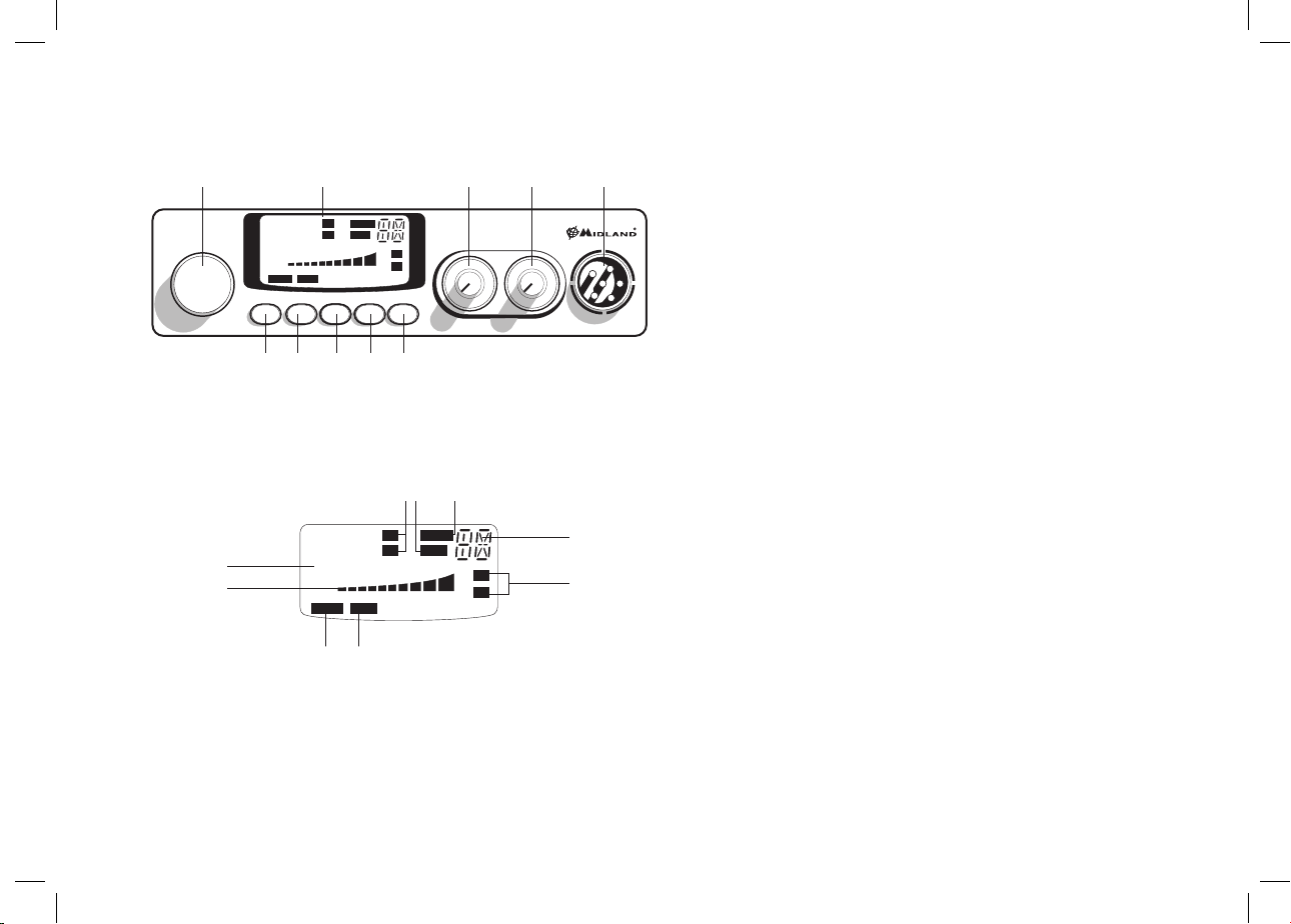
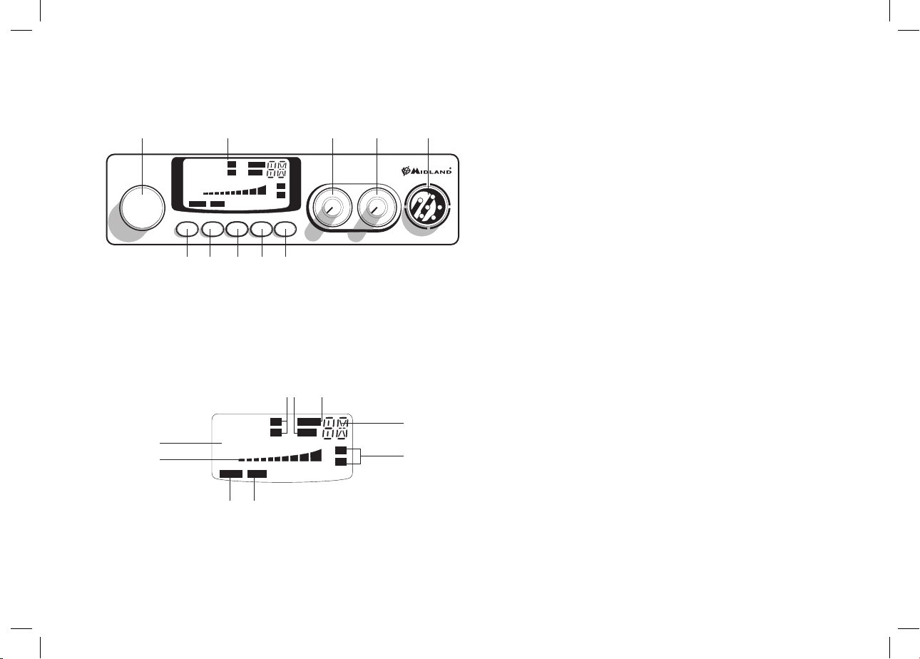
DESCRIZIONE COMANDI
3 4 5 6 7
9 1021 8
FM
SCAN
ALAN 78 PLUS
MULTI
CHANNEL
1. Ricerca manuale canali
2. Display retroilluminato multifunzione:
A
B
A. Numero canali selezionati.
B. Indicatore di intensità del segnale ricevuto e di potenza di segnale
trasmesso
C. AM/FM: indicatore del modo di emissione
D. RX/TX: indicatore ricezione (RX) e trasmissione (TX)
E. SCAN: indicatore funzione SCAN attivata
F. EMG: indicatore lampeggiante canale d’emergenza attivato
2
CH
AM
LOW
SIG
88
1
0.5
EMG Q.UP Q.DOWN AM/FM SCAN
9
5
3
1 2 3 4 PWR
EMGLOCK
88
1
0.5
EMGLOCK
+30
RX
TX
LCR
FM
CH
AM
5
3
1 2 3 4 PWR
FI
C E
H
SCAN
LOW
+30
9
SQUELCH ON/OFF VOL
SIG
RX
TX
G. Indica la banda di frequenza selezionata.
H. LOW: viene visualizzato quando la radio trasmette in bassa potenza
(condizione che si verifica solo per determinate bande di frequenza –
vedi tabella bande).
I. LOCK: Attivazione del blocco tastiera (UP/DOWN) del microfono.
3. Pulsante “EMG” canale d’emergenza: premendo questo tasto si ci posizio-
nerà automaticamente sul canale 9 (canale d’emergenza). Sul display lampeggerà “EMG” e non sarà possibile cambiare accidentalmente il canale.
4.5. Pulsanti “Q.UP/Q.DOWN’’: per selezionare 10 canali verso l’alto (UP) o
verso il basso (DOWN).
6. Pulsante “AM/FM (LCR)”: Per selezionare il modo di emissione (AM/
MICON/OFF
FM). Se lo si preme all’accensione con il tasto “SCAN”, seleziona la banda
operativa. Le relative scelte saranno visualizzate sul display. Se si seleziona
una banda di frequenza che opera solamente la modalità FM, il tasto “AM/
FM” attiva la funzione LCR (richiamo ultimo canale selezionato).
7. Pulsante “SCAN”: tramite questo comando si potrà ricercare automatica-
mente un canale occupato.
• Ruotare lo Squelch in senso orario fino a quando non sparisce il rumore di fondo.
G
D
• Premere il pulsante “SCAN”. Il ricetrasmettitore scansionerà automaticamente e ripetutamente tutti i canali fino a quando non troverà
un canale occupato.
Se lo si preme all’accensione con il tasto “AM/FM”, seleziona la banda
operativa. Le relative scelte saranno visualizzate sul display.
8. Manopola “Squelch” regolazione livello di soglia della ricezione: per la mas-
sima sensibilità del ricevitore è preferibile che il comando sia regolato solo
al preciso livello dove il rumore di fondo del ricevitore viene eliminato.
9. Manopola “ON/OFF-VOLUME”:
Posizione “OFF”: Apparato spento.
Posizione “Volume”: Ruotando la manopola, regolare il volume al livello
desiderato.
10. Presa microfono: inserire lo spinotto del microfono nella presa. Con i tasti
UP/DOWN del microfono, si potranno cambiare manualmente i canali.
I
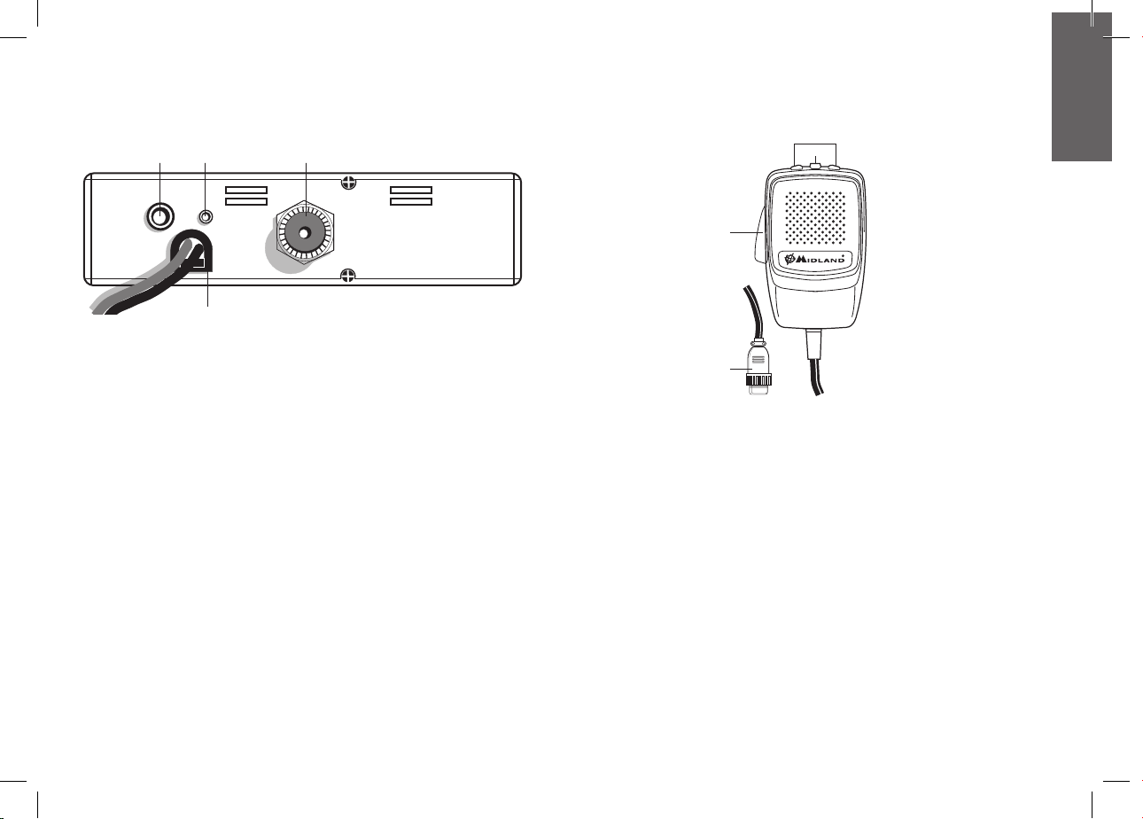
PANNELLO POSTERIORE
111213 14
MICROFONO
2
3
EXT
S. METER
ANTENNA
11. Presa EXT: presa altoparlante esterno (questo collegamento esclude l’uso
dell’alto-parlante interno).
12. Power 12.6 VCC: presa d’alimentazione.
13. Presa S. Meter: permette il collegamento di uno strumento esterno.
14. Connettore antenna: è previsto il connettore SO 239.
1
4
1. PTT: pulsante di trasmissione
2. Pulsanti UP/DOWN:
selezione canali verso l’alto (UP) e verso il basso (DN)
3. Tasto LOCK: permette di bloccare i tasti UP/DOWN del microfono.
4. Connettore microfonico 6 pin
3

INSTALLAZIONE
Ricercare e localizzare, sul mezzo mobile, la posizione per installare l’apparato,
utilizzando la staa di supporto in dotazione o, eventualmente, un estraibile. Tale
posizionamento deve essere fatto in modo da non creare intralcio a chi guida, ma
deve anche essere facilmente accessibile. Praticare i fori (diametro di circa 3 mm)
in una parte metallica per il fissaggio con le viti. Posizionare l’apparato nella staa di
fissaggio. Controllare che le viti siano ben serrate, in considerazione delle notevoli
vibrazioni create dal mezzo mobile.
COLLEGAMENTO ELETTRICO
Prima di procedere in questa operazione, controllare che il ricetrasmettitore sia
spento (posizione OFF= la manopola del volume completamente girata a sinistra,
dopo lo scatto).
L’apparato è dotato di un cavetto d’alimentazione bicolore con un portafusibile inserito sul cavo rosso (positivo). Nel collegamento, è molto importante rispettare la
polarità anche se l’apparato è protetto contro l’inversione accidentale.
Di norma si identifica il polo positivo con il colore rosso o con il segno “+”, e il polo
negativo con il colore nero o con il segno “-”.
Gli stessi segni (o colori) identificativi li troveremo sulla batteria (accumulatore od
altro) e nella scatola dei fusibili dell’automobile. Si raccomanda di collegare in modo
corretto e stabile i terminali del cavetto alla batteria.
ATTENZIONE: Per l’ottimizzazione delle prestazioni si consiglia l’installazione dell’apparecchiatura in luoghi che possano consentire un suciente riciclo d’aria.
INSTALLAZIONE DELL’ANTENNA
Informazioni utili:
1. Installare l’antenna nella parte più alta del veicolo
2. Maggiore è la lunghezza dell’antenna e migliore sarà il suo rendimento
3. Se possibile, installare l’antenna al centro della superficie metallica scelta
4. Tenere il cavo dell’antenna lontano da fonti di disturbi elettrici
5. Assicurarsi di avere una buona massa
6. Evitare danni ai cavi
Attenzione: Non usare mai la radio CB senza aver installato un’antenna appropriata
per non correre il rischio di danneggiare il trasmettitore; per la stessa ragione controllare periodicamente il ROS tramite l’apposito strumento.
SOSTITUZIONE DEL FUSIBILE
Sostituire il fusibile del cavo di alimentazione con un similare di tipo F 2A 250V. I
parametri ed il simbolo del fusibile sono indicati nella seguente etichetta:
F2A 250V +
ISTRUZIONI DI FUNZIONAMENTO
Dopo aver installato e cablato il vostro CB e la vostra antenna, seguire attentamente le seguenti istruzioni per raggiungere un funzionamento soddisfacente del
vostro apparato.
1. Avvitare la spina nella presa del microfono sul pannello e controllare il
montaggio
2. Assicurarsi che l’antenna sia collegata al proprio connettore
3. Assicurarsi che il comando di squelch sia completamente ruotato verso sinistra
4. Accendere l’apparato e regolare il comando del volume per un buon livello
sonoro
5. Selezionare il canale desiderato, cambiando il canale in senso orario o antiorario
6. Per trasmettere, premere il pulsante di trasmissione PTT sul microfono
7. Per ricevere, rilasciarlo
4

I
SELEZIONE BANDE DI FREQUENZA
La scelta delle bande di frequenza deve essere eseguita a seconda del paese nel
quale si intende operare.
Procedimento:
1. Spegnere la radio.
2. Accendere l’apparecchio premendo contemporaneamente i tasti “AM/FM” e
“SCAN”.
3. Ruotare la manopola “CHANNEL” e selezionare la banda di frequenza
desiderata (vedi tabella bande).
4. Premere il tasto “AM/FM” per terminare la selezione.
1
NOTA
: nella banda di frequenza UK è possibile selezionare direttamente la banda EC
premendo il tasto “AM/FM” per 2 secondi circa.
2
: se si seleziona una banda di frequenza che opera solamente la modalità FM, il
NOTA
tasto “AM/FM” attiva la funzione LCR (richiamo ultimo canale selezionato).
TABELLA BANDE DI FREQUENZA
Sigla sul display Paese
I Italia 40 CH AM/FM 4Watt
I2 Italia 34 CH AM/FM 4Watt
D4 Germania 80 CH FM 4Watt / 40 CH AM 4Watt
EU Europa 40 CH FM 4Watt / 40 CH AM 1Watt
EC CEPT 40 CH FM 4Watt
E Spagna 40 CH AM/FM 4Watt
F Francia 40 CH FM 4Watt / 40 CH AM 1Watt
PL Polonia 40 CH AM/FM 4W
UK Inghilterra 40 CH FM 4 Watt frequenze inglesi + EC 40 CH
FM 4Watt frequenze CEPT
ATTENZIONE! Lo standard sicuramente riconosciuto in tutti i paesi europei è 40CH
FM 4W (EC) - vedi tabella “Restrizioni all’uso”.
5

CARATTERISTICHE TECNICHE
GENERALI
Canali.................................................................................................(vedi tabella bande)
Gamma di frequenza* ..............................................................26.565-27.99125 MHz
Ciclo di utilizzo (% su 1 ora) .........................................TX 5%; RX 5%; Stand-by 90%
Controllo di frequenza ........................................................................................... a PLL
Temperatura .................................................................................................-10° ± 55°C
Tensione d’alimentazione .....................................................................12.6V CC ±10%
Dimensione .................................................................... 180 (L)* 35 (H)* 140 (P) mm
Peso ....................................................................................................................0,850 kg
RICEVITORE
Sistema ricevente.............................................. Supereterodina a doppia conversione
Frequenza intermedia ......................................... I° IF: 10.695 MHz • II° IF: 455 KHz
Sensibilità ................................................................................0.5µV per 20dB SINAD
Potenza d’uscita audio @10% THD ..................................................2.0W @ 8 Ohm
Distorsione audio ....................................................................... meno dell’8% @ 1KHz
Reiezione alle immagini ...........................................................................................65dB
Selettività sul canale ................................................................................................65dB
Rapporto segnale disturbo ..................................................................................... 45dB
Assorbimento all’attesa ...................................................................................... 250mA
TRASMETTITORE
Potenza d’uscita .................................................................................................4W max
Modulazione ...............................................................................FM: 1,8KHz ± 0,2KHz
........................................................................................................... AM: da 85% a 95%
Frequenza di risposta ..............................................................................300 Hz/3 KHz
Impedenza d’uscita...................................................................RF 50 Ohm sbilanciato
Rapporto segnale disturbo ...........................................................................40 dB MIN
Corrente assorbita ............................................................................................. 1100mA
* (considerando tutte le bande di frequenza europee approvate)
Le specifiche sono soggette a modifiche senza preavviso.
Un dispositivo di sezionamento adatto deve essere previsto nell’impianto elettrico. Tale dispositivo deve disconnettere entrambi i poli simultaneamente.
6

UK
INDEX
Introduction Pag.1
Function and location of the controls Pag. 2
Installation Pag.4
Power supply Pag. 4
Installing an antenna Pag. 4
How to operate with your transceiver Pag. 4
Frequency band selection Pag. 4
Frequency band chart Pag. 5
Technical specifications Pag. 6
Your ALAN 78PLUS MULTI B represents the state-of-the art in high-tech engineering. Designed for the Citizen Band Mobile operation, this compact package
is big in performance. It is a quality piece of electronic equipment, skillfully constructed with the finest components. The circuitry is all a solid-state, mounted on
rugged printed circuit boards. It is designed for many years of reliable, trouble-free
performance.Your mobile CB has a built Phase-Locked Loop synthesizer circuit.
The PLL circuit achieves a new technique for generating all the required frequencies with fewer crystals. The result is much tighter frequency control and superior
reliability.
1
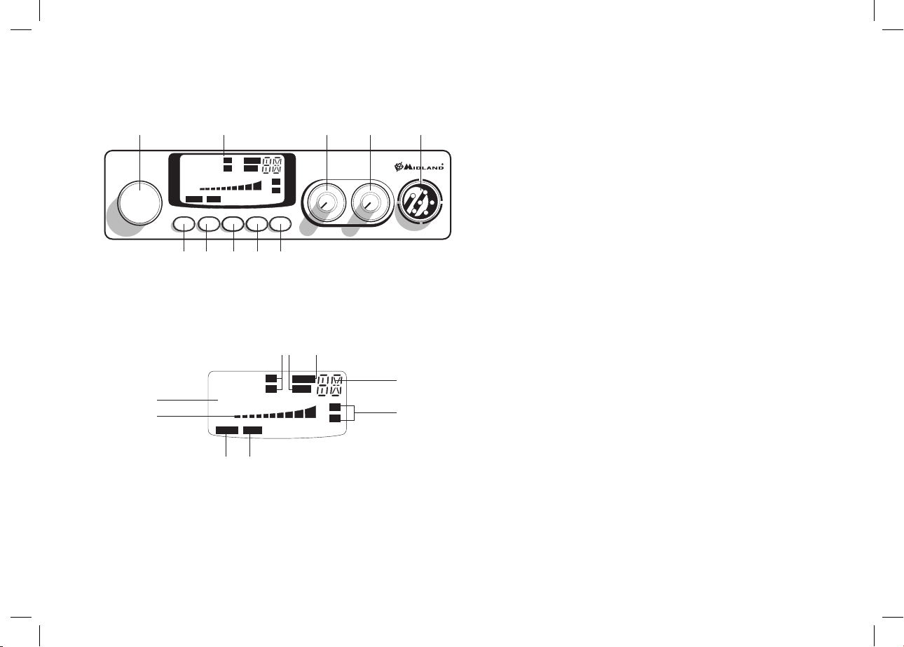
FUNCTION AND LOCATION
3 4 5 6 7
OF THE CONTROLS
9 1021 8
FM
SCAN
ALAN 78 PLUS
MULTI
CHANNEL
1. Channel selector
2. Multifunction backlighted display. It shows:
A
B
A. Channel selected number
B. The received signal strength and the power of the transmitting signal
C. AM/FM mode
2
CH
AM
LOW
SIG
88
1
0.5
EMG Q.UP Q.DOWN AM/FM SCAN
9
5
3
1 2 3 4 PWR
EMGLOCK
88
1
0.5
EMGLOCK
+30
RX
TX
LCR
FM
CH
AM
5
3
1 2 3 4 PWR
FI
C E
H
SCAN
LOW
+30
9
SQUELCH ON/OFF VOL
SIG
RX
TX
D. RX/TX:TX=transmit mode; RX=receive mode
E. SCAN mode
F. EMG mode
G. Frequency band selected.
H. LOW: displayed when the radio transmits in low power (this mode is
possible with some frequency bands only – see the Frequency band
chart).
I. LOCK: microphone (UP/DOWN buttons) lock enabled.
3. ”EMG” button: Emergency channel. By pressing it, you will be automa-
tically positioned on CH 9 (emergency channel). The display will show
MICON/OFF
“EMG”. It will not be possibile to change accidentally the channel.
4. 5. “Q.UP/Q.DOWN” buttons: To skip 10 channels UP (Q. UP) or 10 chan-
nels DOWN (Q.DOWN).
6. “AM/FM”(LCR) button: To select AM or FM mode. If you switch on the
unit and push “AM/FM”(LCR) and “SCAN” at the same time, you will
select the operating band, which will be visualised on the display.
If you select a frequency band operating in FM mode only, this button
enables the LCR function (Last Channel Recall).
G
D
7. “SCAN” button: With this control, you can automatically seek for a busy
channel.
Turn the Squelch clockwise until the background noise is no longer heard.
Press the “SCAN” button: the transceiver will scan automatically all the
channels.
If you switch on the unit and push “SCAN” and “AM/FM”(LCR) at the
same time, you will select the operating band, which will be visualised on
the display.
8. “Squelch” Control: For the maximum receiver sensitivity, the control must
be regulated exactly where the receiver background noise disappears.
9. “ON/OFF Volume” Control. In “OFF” position your transceiver is OFF.
Turn this control clockwise to switch on the unit. Turn the knob clockwise a
little more to set the audio level, until you get a comfortable reception.
10. Microphone jack: Insert the mic connector into this jack.

UK
REAR PANEL
MICROPHONE
111213 14
EXT
S. METER
ANTENNA
11. ”EXT” jack: external loudspeaker jack.(the internal loudspeaker is excluded)
12. Power 12.6V DC: power supply cable
13. S.Meter jack: it allows an external “S. Meter” connection
14. Antenna connector (SO239 connector type)
2
3
1
4
1. PTT: transmission button
2. UP/DOWN buttons: manual channels selector.
3. LOCK button: it allows you to lock the UP/DOWN buttons.
4. 6 pin microphone connector
3

INSTALLATION
Safety and convenience are the primary consideration for mounting any piece of
mobile equipment. All controls must readily available to the operator without interfering with the movements necessary for safe operation of the vehicle. Set the
proper position in the car to install the transceiver using the supplied supporting
bracket or eventually the slide bracket. Tighten the retaining screws. The fixing bracket must be close to metallic parts.
REPLACING FUSE
If you replace the fuse for DC power Cord, use F 2A 250V type. The parameters
and the symbol of the fuse are indicated in the following label.
F2A 250V +
POWER SUPPLY
Be sure the transceiver is OFF. In the direct-voltage power supply, is very important to observe the polarity even if the unit is protected against the accidental
inversion:
Red = positive pole (+)
Black = negative pole (-)
The same colors are present on the battery and in the fuse box of the car. Correctly
connect the cable terminal to the battery.
ATTENTION: To obtain best performances we recommend to install the radio in a
place with enough air circulation.
INSTALLING AN ANTENNA
1. Place the antenna as high as possible
2. The longer is the antenna, the better will be the performance
3. If possible, mount the antenna in the center of whatever surface you choose
4. Keep antenna cable away from noise sources, such as the ignition switch,
gauges,etc.
5. Make sure you have a solid metal-to-metal ground connection.
6. Prevent cable damage during antenna installation.
WARNING: To avoid damage, never operate your CB radio without connecting a
proper antenna. A periodical control of the cable and of the S.W.R. is recommended.
4
HOW TO OPERATE WITH YOUR TRANSCEIVER
1. Screw the microphone plug into the microphone jack.
2. Make sure your antenna is securely connected to the antenna connector.
3. Make sure the SQUELCH control is turned fully counterclockwise.
4. Turn on the unit and adjust the volume control.
5. Select your desired channel.
6. To transmit, press the PTT button and speak in a normal tone of voice.
7. To receive, release the PTT button.
FREQUENCY BAND SELECTION
The frequency bands must be chosen according to the country where you are
going to operate.
Procedure:
1. Switch o the unit.
2. Turn it on while pushing the “AM/FM” e “SCAN” buttons at the same time.
3. Rotate the “CHANNEL” knob and select the desired frequency band (see the
chart here below).
4. To stop your selection, press the “AM/FM” button.
1
: In the UK frequency band, you can select directly the EC band by pushing the
NOTE
“AM/FM” button for 2 seconds.
2
: If you select a frequency band which operates in FM mode only, the “AM/FM”
NOTE
control enables the LCR function (last channel recall).

UK
FREQUENCY BAND CHART
Digits displayed Country
I Italy 40 CH AM/FM 4Watt
I2 Italy 34 CH AM/FM 4Watt
D4 Germany 80 CH FM 4Watt / 40 CH AM 4Watt
EU Europe 40 CH FM 4Watt / 40 CH AM 1Watt
EC CEPT 40 CH FM 4Watt
E Spain 40 CH AM/FM 4Watt
F France 40 CH FM 4Watt / 40 CH AM 1Watt
PL
UK England 40 CH FM 4 Watt English frequencies + EC 40
ATTENTION!
The frequency band definitely allowed all over Europe is 40 CH FM 4W (EC).
Poland 40 CH AM/FM 4Watt
CH FM 4Watt CEPT frequencies
TECHNICAL SPECIFICATIONS
GENERAL
Channels ......................................................................(see the frequency band chart)
Frequency Range* ..................................................................26.565-27.99125 MHz
Duty cycle (% on 1 hour) ........................................ TX 5% - RX 5% - Stand-by 90%
Frequency Control ................................................................................................... PLL
Operating Temperature Range ................................................................. -10°/+55° C
DC input voltage ..................................................................................12.6V DC ±10%
Size....................................................................................180 (L)x35 (H)x140 (P) mm
Weight ................................................................................................................0,850 kg
RECEIVER
Receiving system .....................................................dual conversion superheterodyne
Intermediate frequency .....................................I° IF: 10.695 MHz • II° IF: 455 KHz
Sensitivity .........................................................0.5µV for 20 dB SINAD in FM mode
...........................................................................0.5µV for 20 dB SINAD in AM mode
Audio output power @10% THD ..................................................... 2.0 W @ 8 Ohm
Audio distortion ...........................................................................less than 8% @ 1 KHz
Image rejection ........................................................................................................65 dB
Adjacent channel rejection ....................................................................................65 dB
Signal/Noise ratio ................................................................................................... 45 dB
Current drain at stand/by................................................................................... 250mA
TRANSMITTER
Output power ......................................................................................................4W max
Modulation .......................................AM: from 85% to 95% FM: 1,8 KHz ± 0,2 KHz
Frequency response ...............................................................................300 Hz/3 KHz
Output impedance ................................................................ RF 50 Ohm unbalanced
Signal/Noise Ratio ........................................................................................40 dB MIN
Current drain ......................................................................................................1100mA
* (covering all approved EU frequency bands)
Specifications are subject to change without notice.
A readily accessible disconnect device shall be incorporated in the installation wiring. The discon-
nect device shall disconnect both poles simultaneously.
5

6

D
INHALT
Einführung Seite 1
Funktion und Lage der Bedienelemente Seite 2
Einbau des ALAN 78PLUS MULTI B im Kraftfahrzeug Seite 4
Anschluß an die Spannungsversorgung Seite 4
Montage der Antenne Seite 4
Bedienung Ihres ALAN 78PLUS MULTI B Seite 4
Ihr CB-Mobilfunkgerät ALAN 78PLUS MULTI B verkörpert den aktuellen Stand
der Entwicklung auf dem Gebiet der Funkgerätetechnik. Dank der kompakten
Abmessungen und der kompromißlosen Auslegung für den Mobilbetrieb wird die
besondere Leistungsfähigkeit auf allen CB-Kanälen sichergestellt. Sie haben ein
elektronisches Qualitätsprodukt vor sich, das professionell konstruiert und mittels
ausgesuchter, erstklassiger Komponenten gebaut worden ist. Eine leistungsfähige
Halbleitertechnik mit aktueller PLL-Schaltung ermöglicht durch ihre hohe Frequenzkonstanz und dem Auau auf einer stabilen Leiterplatte einen jahrelang
störungsfreien Betrieb Ihres Gerätes.
Auswahl der Frequenzbänder Seite 5
Frequenztabelle Seite 5
Technische Daten Seite 6
1
FUNKTION UND LAGE DER BEDIENELE-
3 4 5 6 7
MENTE
9 1021 8
FM
SCAN
ALAN 78 PLUS
MULTI
CHANNEL
1. Kanalwahlschalter: mit diesem Schalter lassen sich die Kanäle einstellen.
2. Multifunktions-Display mit Hintergrundbeleuchtung. Im Display werden
die folgenden Informationen angezeigt:
A
B
A. Zweistellige Kanalanzeige
B. Relative Empfangsfeldstärke und Sendeleistung
C. AM/FM-Betriebsart
D. RX-/TX-Anzeige: TX = Sendebetrieb, RX = Empfangsbetrieb
2
CH
AM
LOW
SIG
88
1
0.5
EMG Q.UP Q.DOWN AM/FM SCAN
9
5
3
1 2 3 4 PWR
EMGLOCK
88
1
0.5
EMGLOCK
+30
RX
TX
LCR
FM
CH
AM
5
3
1 2 3 4 PWR
FI
C E
H
SCAN
LOW
+30
9
SQUELCH ON/OFF VOL
SIG
RX
TX
MICON/OFF
G
D
E. SCAN-Betrieb, Suchlauf nach belegten Kanälen
F. EMG-Kanal, Fernfahrer-/Notruf-Kanal
G. Zeigt das gewählte Frequenzband an.
H. LOW: erscheint, wenn das Funkgerät auf niedrige Ausgangsleistung
schaltet (betrifft nur bestimmte Frequenzbänder – siehe
Frequenztabelle)
I. LOCK: Aktivierung der Mikrofon-Tastaturverriegelung (UP/
DOWN).
3. Kanal 9 Direkttaste, EMG: Auf Knopfdruck läßt sich der Notrufkanal 9
direkt einschalten. In der Anzeige erscheint der Schriftzug “EMG”. Ein
anderer Kanal läßt sich nicht einstellen, solange der EMG-Kanal aktiv ist.
4. 5. 10-Kanal-Tasten, Q.UP und Q.DOWN: Drücken der Q. UP-Taste schaltet
10 Kanäle höher, Q. DOWN schaltet 10 Kanäle tiefer.
6. Taste “AM/FM” (LCR): Zur Auswahl der gewünschten Betriebsart (AM/
FM). Hält man beim Einschalten die Tasten “AM/FM” und “SCAN”
gleichzeitig gedrückt, kommt man in die Frequenzbandauswahl. Die
entsprechende Wahl wird im Display angezeigt.
Wird ein Frequenzband gewählt, das nur in der Betriebsart FM arbeitet,
übernimmt die Taste “AM/FM” statt der Betriebsartwahl die LCRFunktion (Last Channel Recall – Aufruf des zuletzt genutzten Kanals).
7. Suchlauftaste, SCAN: Durch Einschalten des Suchlaufbetriebs lassen
sich belegte Kanäle automatisch suchen. Dazu muß die Rauschsperre so
aktiviert sein, daß das Hintergrundrauschen unterdrückt wird. Drücken der
Scan-Taste startet den Suchlauf. Der Suchlauf stoppt, sobald ein belegter
Kanal gefunden ist. Hält man beim Einschalten die Tasten “AM/FM” und
“SCAN” gleichzeitig gedrückt, kommt man in die Frequenzbandauswahl.
Die entsprechende Wahl wird im Display angezeigt.
8. Rauschsperre, Squelch: Um die höchstmögliche Empfangsempfindlichkeit
zu nutzen, muß der Regler so eingestellt werden, daß das
Hintergrundrauschen gerade unterdrückt wird.
9. Ein/Aus-Schalter, Lautstärkeregler: In der Stellung “OFF” ist Ihr
ALAN 78PLUS MULTI B ausgeschaltet. Durch Drehen des Reglers
im Uhrzeigersinn wird das Gerät eingeschaltet. Weiteres Drehen im
Uhrzeigersinn erhöht die Wiedergabelautstärke nach Wunsch.
10. Mikrofonbuchse: Hier wird der Stecker des Mikrofons eingesteckt.
 Loading...