

Page 1
ALAN 78 PLUS MULTI
Page 2

ENGLISH
1
INDEX
Introduction Pag.1
Function and location of the controls Pag. 2
Installation Pag.4
Power supply Pag. 4
Installing an antenna Pag. 4
How to operate with your transceiver Pag. 5
Frequency band selection Pag. 5
Frequency band chart Pag. 5
Technical specifications Pag. 6
Your ALAN 78 PLUS MULTI represents the state-of-the art in high-tech engineering.
Designed for the Citizen Band Mobile operation, this compact package is big in
performance. It is a quality piece of electronic equipment, skillfully constructed with
the finest components. The circuitry is all a solid-state, mounted on rugged printed
circuit boards. It is designed for many years of reliable, trouble-free performance.
Your mobile CB has a built Phase-Locked Loop synthesizer circuit.
The PLL circuit achieves a new technique for generating all the required frequen-
cies with fewer crystals. The result is much tighter frequency control and superior
reliability.
Important Note
Following national regulations have been modified:
Residents of Belgium, Great Britain, Spain and Switzerland need a CB licence in
their countries, while visitors may use their CB radios in FM free of licence, for AM
they should be able to present their home-country’s licence document. In Italy, even
visitors need a valid Italian authorization.
Austria does not accept any multi-standard or programmable CB radio. Please
respect this requirement and do not use Your radio during driving through Austria.
In Germany transmitting as a base station on channels 41-80 is restricted in some
areas along the country borders. No restrictions apply for mobile use. More details
can be obtained from the local RegTP authority office.
Changes in European or national regulations will be published on the service website
of ALAN-Albrecht under www.alan-albrecht.info
Page 3
2
FUNCTION AND LOCATION OF THE CONTROLS
1. Channel selector
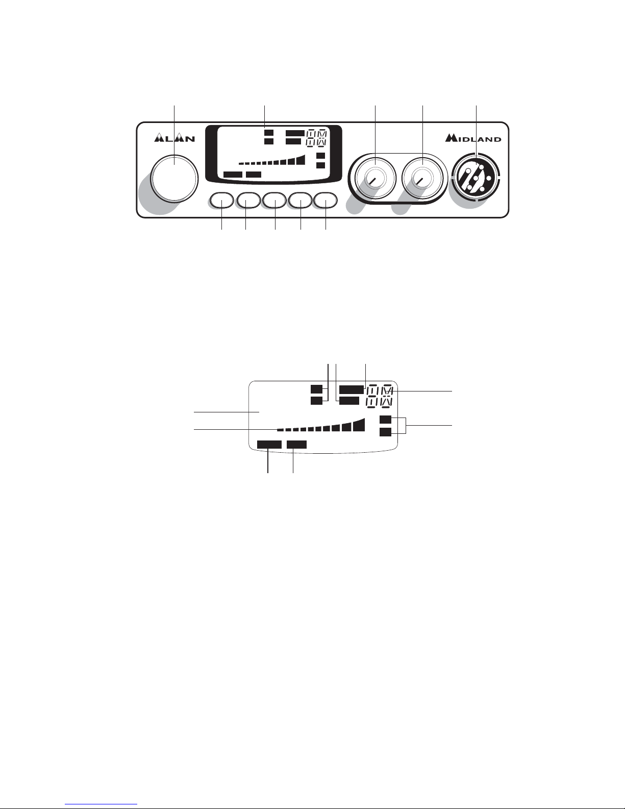
2. Multifunction backlighted display. It shows:
A. Channel selected number
B. The received signal strength and the power of the transmitting signal
C. AM/FM mode
D. RX/TX:TX=transmit mode; RX=receive mode
E. SCAN mode
F. EMG mode
G. Frequency band selected.
H. LOW: displayed when the radio transmits in low power (this mode is pos-
sible with some frequency bands only – see the Frequency band chart).
I. LOCK: microphone (UP/DOWN buttons) lock enabled.
3. ”EMG” button: Emergency channel. By pressing it, you will be automatically
positioned on CH 9 (emergency channel). The display will show “EMG”. It will
not be possibile to change accidentally the channel.
4. 5. “Q.UP/Q.DOWN” buttons: To skip 10 channels UP (Q. UP) or 10 channels
DOWN (Q.DOWN).
6. “AM/FM”(LCR) button: To select AM or FM mode. If you switch on the unit
and push “AM/FM”(LCR) and “SCAN” at the same time, you will select the
78 PLUS MULTI
CHANNEL
EMG Q.UP Q.DOWN AM/FM SCAN
SQUELCH ON/OFF VOL
MICON/OFF
3 4 5 6 7
9 1021 8
CH
5
9
+30
SIG
0.5
1 2 3 4 PWR
FM
AM
LOW
SCAN
EMGLOCK
TX
RX
LCR
1
3
CH
1
3
5
9
+30
SIG
0.5
1 2 3 4 PWR
A
CE
G
D
FI
B
H
LOW
SCAN
TX
RX
FM
AM
EMGLOCK
Page 4

ENGLISH
3
operating band, which will be visualised on the displayed.
If you select a frequency band operating in FM mode only, this button enables
the LCR function (Last Channel Recall).
7. "SCAN" button: With this control, you can automatically seek for a busy chan-
nel.
Turn the Squelch clockwise until the background noise is no longer heard.
3UHVVWKH6&$1EXWWRQWKHWUDQVFHLYHUZLOOVFDQDXWRPDWLFDOO\DOOWKHFKDQ-
nels until a carrier is being received. If you switch on the unit and push “SCAN”
and “AM/FM”(LCR) at the same time, you will select the operating band, which
will be visualised on the displayed.
8. "Squelch" Control: For the maximum receiver sensitivity, the control must be
regulated exactly where the receiver background noise disappears.
9. “ON/OFF Volume” Control.,Q2)) SRVLWLRQ \RXUWUDQVFHLYHULV 2))7XUQ
this control clockwise to switch on the unit. Turn the knob clockwise a little
more to set the audio level, until you get a comfortable reception.
10. Microphone jack: Insert the mic connector into this jack.
REAR PANEL
11. ”EXT” jack: external loudspeaker jack.(the internal loudspeaker is excluded)
12. Power 13.8V DC: power supply cable
13. S.Meter jack: it allows an external “S. Meter” connection
14. Antenna connector (SO239 connector type)
EXT
S. METER
DC13,8V
ANTENNA
11
12
13 14
Page 5

4
MICROPHONE
1. PTT: transmission button
2. UP/DOWN buttons: manual channels selector.
3. LOCK button: it allows you to lock the UP/DOWN buttons.
4. 6 pin microphone connector
INSTALLATION
Safety and convenience are the primary consideration for mounting any piece of
mobile equipment. All controls must readily available to the operator without interfering with the movements necessary for safe operation of the vehicle. Set the proper
position in the car to install the transceiver using the supplied supporting bracket or
eventually the slide bracket. Tighten the retaining screws. The fixing bracket must
be close to metallic parts.
POWER SUPPLY
Be sure the transceiver is OFF. In the direct-voltage power supply, is very important
to observe the polarity even if the unit is protected against the accidental inversion:
5HG SRVLWLYHSROH
Black = negative pole (-)
The same colors are present on the battery and in the fuse box of the car. Correctly
connect the cable terminal to the battery.
ATTENTION
To obtain best performances we recommend to install the radio in a place with
enough air circulation.
INSTALLING AN ANTENNA
1.Place the antenna as high as possible
2.The longer the antenna, the better will be the performance
3.If possible, mount the antenna in the center of whatever surface you choose
4.Keep antenna cable away from noise sources, such as the ignition switch,
gauges,etc.
5.Make sure you have a solid metal-to-metal ground connection.
6.Prevent cable damage during antenna installation.
WARNING: To avoid damage, never operate your CB radio without connecting a
proper antenna. A periodical control of the cable and of the S.W.R. is recommended.
4
2
1
3
Page 6

ENGLISH
5
HOW TO OPERATE WITH YOUR TRANSCEIVER
1.Screw the microphone plug into the microphone jack.
2.Make sure your antenna is securely connected to the antenna connector.
3.Make sure the SQUELCH control is turned fully conterclockwise.
4.Turn on the unit and adjust the volume control.
5.Select your desired channel.
6.To transmit, press the PTT button and speak in a normal tone of voice.
7.To receive, release the PTT button.
FREQUENCY BAND SELECTION
The frequency bands must be chosen according to the country where you are going
to operate.
Procedure:
Switch off the unit.
Turn it on while pushing the “AM/FM” e “SCAN” buttons at the same time.
Rotate the “CHANNEL” knob and select the desired frequency band (see the chart
here below).
To stop your selection, press the “AM/FM” button.
NOTE1: In the UK frequency band, you can select directly the EC band by pushing
the “AM/FM” button for 2 seconds.
NOTE2: If you select a frequency band which operates in FM mode only, the “AM/
FM” control enables the LCR function (last channel recall).
FREQUENCY BAND CHART
Digits displayed Country
I Italy 40 CH AM/FM 4Watt
I2 Italy 34 CH AM/FM 4Watt
D Germany 80 CH FM 4Watt / 12 CH AM 1Watt
D2 Germany 40 CH FM 4Watt / 12 CH AM 1Watt
D3 Germany 80 CH FM 4Watt / 40 CH AM 1Watt
EU Europe 40 CH FM 4Watt / 40 CH AM 1Watt
EC CEPT 40 CH FM 4Watt
E Spain 40 CH AM/FM 4Watt
F France 40 CH FM 4Watt / 40 CH AM 1Watt
PL Poland 40 CH AM/FM 4Watt
UK (QJODQG&+ )0 :DWW(QJOLVK IUHTXHQFLHV (& &+
FM 4Watt CEPT frequencies
ATTENTION!
The frequency band definitely allowed all over Europe is 40 CH FM 4W (EC).
Page 7

6
TECHNICAL SPECIFICATIONS
GENERAL
Channels ....................................................40 FM (see the frequency band chart)
Frequency Range ................................................................... 26.565-27.99125 MHz
Frequency Control ............................................................................................... PLL
Operating Temperature Range .................................................................-10°/+55° C
DC input voltage ...............................................................................13.8V DC ±15%
Size.................................................................................180 (L)x35 (H)x140 (P) mm
Weight .......................................................................................................... 0,850 kg
RECEIVER
Receiving system ..............................................dual conversion superheterodyne
Intermediate frequency .......................................,,)0+],,,).+]
Sensitivity ........................................................0.5µV for 20 dB SINAD in FM mode
........................................................................ 0.5µV for 20 dB SINAD in AM mode
Audio output power @10% THD...................................................... 2.0 W @ 8 Ohm
Audio distortion......................................................................less than 8% @ 1 KHz
Image rejection..................................................................................................65 dB
Adjacent channel rejection ................................................................................65 dB
Signal/Noise ratio ..............................................................................................45 dB
Current drain at stand/by................................................................................. 250mA
TRANSMITTER
Output power.........................................................duty cycle 10% 4W @ 13.8V DC
Modulation..............................................................................AM: from 85% to 95%
...............................................................................................FM: 1,8 KHz ± 0,2 KHz
Frequency response............................................................ from 400 Hz to 2.5 KHz
Output impedance .............................................................. RF 50 Ohm unbalanced
Signal/Noise Ratio..................................................................................... 40 dB MIN
Current drain ..................................1100mA (Power position with no modulation)
All specifications are subject to change without notice.
Page 8

Produced or imported by: CTE INTERNATIONAL srl
Via. R.Sevardi 7, 42010 Mancasale - Reggio Emilia - Italy - www.cte.it
 Loading...