

Page 1

ITALIANO
1
INDICE
Introduzione Pag. 1
Descrizione comandi Pag. 2
Installazione Pag. 4
Collegamento elettrico Pag. 4
Installazione dell'antenna Pag. 4
Istruzioni di funzionamento dell’Alan 78 Plus Multi Pag. 5
Selezione delle bande di frequenza Pag. 5
Tabella bande di frequenza Pag. 5
Caratteristiche tecniche Pag. 6
ALAN 78 PLUS MULTI operante sui canali della banda cittadina, ha come importante ed
innovativa peculiarità di essere controllato a microprocessore. Apparato estremamente
compatto, è frutto delle più avanzate tecnologie e garantisce il massimo delle prestazioni
e del rendimento, essendo stato costruito utilizzando i migliori componenti. La circuiteria,
tutta allo stato solido, è montata su robusti circuiti stampati, garantendo un uso per molti
anni anche nelle situazioni più gravose. ALAN 78 PLUS MULTI è sintetizzato in frequenza
tramite circuito PLL, soluzione che permette di generare, tramite un quarzo le frequenze
richieste, consentendo una maggior affidabilità e flessibilità nel controllo delle stesse.
Page 2
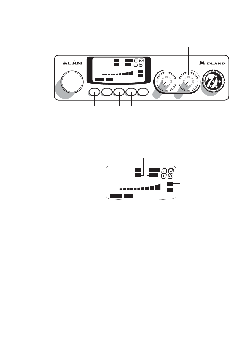
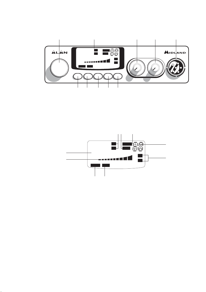
DESCRIZIONE COMANDI
1. Ricerca manuale canali
2. Display retroilluminato multifunzione:
A. Numero canali selezionati.
B. Indicatore di intensità del segnale ricevuto e di potenza di segnale trasmesso
C. AM/FM: indicatore del modo di emissione
D.RX/TX: indicatore ricezione (RX) e trasmissione (TX)
E. SCAN: indicatore funzione SCAN attivata
F. EMG: indicatore lampeggiante canale d’emergenza attivato
G.Indica la banda di frequenza selezionata.
H.LOW: viene visualizzato quando la radio trasmette in bassa potenza (condizione che
si verifica solo per determinate bande di frequenza – vedi tabella bande).
I. LOCK: Attivazione del blocco tastiera (UP/DOWN) del microfono.
3. Pulsante “EMG” canale d’emergenza: premendo questo tasto si ci posizionerà auto-
maticamente sul canale 9 (canale d’emergenza). Sul display lampeggerà “EMG” e non
sarà possibile cambiare accidentalmente il canale.
4.5. Pulsanti “Q.UP/Q.DOWN’’: per selezionare 10 canali verso l’alto (UP) o verso il basso
(DOWN).
2
78 PLUS MULTI
CHANNEL
EMG Q.UP Q.DOWN AM/FM SCAN
SQUELCH ON/OFF VOL
MICON/OFF
3 4 5 6 7
9 1021 8
88
CH
5
9
+30
SIG
0.5
123 4PWR
FM
AM
LOW
SCAN
EMGLOCK
TX
RX
LCR
1
3
88
CH
1
3
5
9
+30
SIG
0.5
123 4PWR
FM
AM
LOW
SCAN
EMGLOCK
TX
RX
A
CE
G
D
FI
B
H
Page 3
ITALIANO
6. Pulsante “AM/FM (LCR)”: Per selezionare il modo di emissione (AM/FM). Se lo si
preme all’accensione con il tasto “SCAN”, seleziona la banda operativa. Le relative
scelte saranno visualizzate sul display. Se si seleziona un banda di frequenza che opera
solamente la modalità FM, il tasto “AM/FM” attiva la funzione LCR (richiamo ultimo
canale selezionato).
7. Pulsante "SCAN": tramite questo comando si potrà ricercare automaticamente un
canale occupato.
• Ruotare lo Squelch in senso orario fino a quando non sparisce il rumore di fondo.
•Premere il pulsante "SCAN". Il ricetrasmettitore scansionerà automaticamente e
ripetutamente tutti i canali fino a quando non troverà un canale occupato.
Se lo si preme all’accensione con il tasto “AM/FM”, seleziona la banda operativa. Le
relative scelte saranno visualizzate sul display.
8. Manopola "Squelch" regolazione livello di soglia della ricezione: per la massima sen-
sibilità del ricevitore è preferibile che il comando sia regolato solo al preciso livello
dove il rumore di fondo del ricevitore viene eliminato.
9. Manopola "ON/OFF-VOLUME":
Posizione "OFF": Apparato spento.
Posizione "Volume": Ruotando la manopola, regolare il volume al livello desiderato.
10. Presa microfono: inserire lo spinotto del microfono nella presa. Con i tasti UP/DOWN
del microfono, si potranno cambiare manualmente i canali.
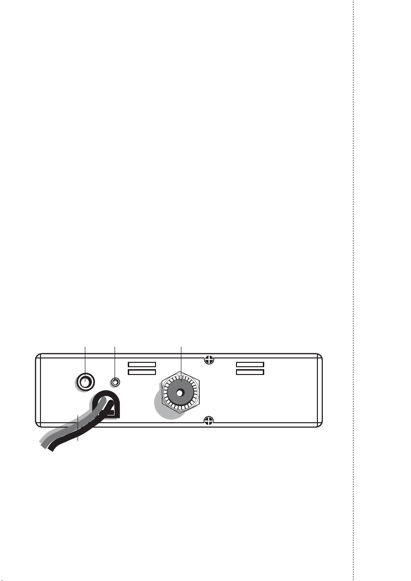
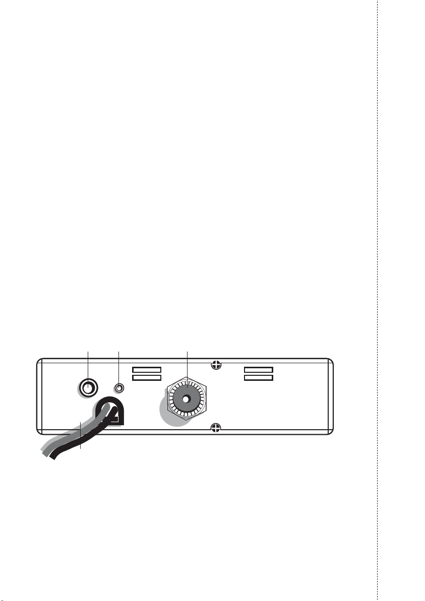
PANNELLO POSTERIORE
11. Presa EXT: presa altoparlante esterno (questo collegamento esclude l’uso dell’alto-
parlante interno).
12. Power 13.8 VCC: presa d'alimentazione.
13. Presa S. Meter: permette il collegamento di uno strumento esterno.
14. Connettore antenna: è previsto il connettore SO 239.
3
EXT
S. METER
DC
13,8V
ANTENNA
11
12
13 14
Page 4
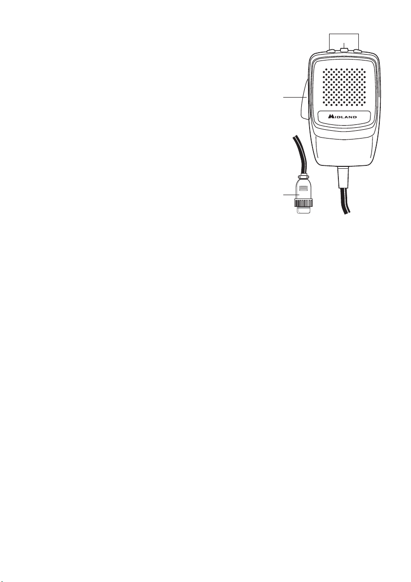
MICROFONO
1. PTT: pulsante di trasmissione
2. Pulsanti UP/DOWN:
selezione canali verso l’alto (UP) e verso il basso
(DN)
3. Tasto LOCK: permette di bloccare i tasti UP/DOWN
del microfono.
4. Connettore microfonico 6 pin
INSTALLAZIONE
Ricercare e localizzare, sul mezzo mobile, la posizione per installare l’apparato, utilizzando
la staffa di supporto in dotazione o, eventualmente, un estraibile. Tale posizionamento deve
essere fatto in modo da non creare intralcio a chi guida, ma deve anche essere facilmente accessibile. Praticare i fori (diametro di circa 3 mm) in una parte metallica per il fissaggio con le viti. Posizionare l’apparato nella staffa di fissaggio. Controllare che le viti siano
ben serrate, in considerazione delle notevoli e vibrazioni create dal mezzo mobile.
COLLEGAMENTO ELETTRICO
Prima di procedere in questa operazione, controllare che il ricetrasmettitore sia spento
(posizione OFF= la manopola del volume completamente girata a sinistra, dopo lo scatto).
L’apparato è dotato di un cavetto d'alimentazione bicolore con un portafusibile inserito sul
cavo rosso (positivo). Nel collegamento, è molto importante rispettare la polarità anche se
l’apparato è protetto contro l’inversione accidentale.
Di norma si identifica il polo positivo con il colore rosso o con il segno "+", e il polo negativo con il colore nero o con il segno "-".
Gli stessi segni (o colori) identificativi li troveremo sulla batteria (accumulatore od altro) e
nella scatola dei fusibili dell’automobile. Si raccomanda di collegare in modo corretto e stabile i terminali del cavetto alla batteria.
INSTALLAZIONE DELL’ANTENNA
Informazioni utili:
1. Installare l’antenna nella parte più alta del veicolo
2. Maggiore è la lunghezza dell’antenna e migliore sarà il suo rendimento
3. Se possibile, installare l’antenna al centro della superficie metallica scelta
4. Tenere il cavo dell’antenna lontano da fonti di disturbi elettrici
5. Assicurarsi di avere una buona massa
6. Evitare danni ai cavi
Attenzione: Non usare mai la radio CB senza aver installato un’antenna appropriata per
non correre il rischio di danneggiare il trasmettitore; per la stessa ragione controllare
periodicamente il ROS tramite l’apposito strumento.
4
4
2
1
3
Page 5
ITALIANO
ISTRUZIONI DI FUNZIONAMENTO DELL’ALAN 78 PLUS MULTI
Dopo aver installato e cablato il vostro CB e la vostra antenna, seguire attentamente le
seguenti istruzioni per raggiungere un funzionamento soddisfacente del vostro apparato.
1. Avvitare la spina nella presa del microfono sul pannello e controllare il montaggio
2. Assicurarsi che l’antenna sia collegata al proprio connettore
3. Assicurarsi che il comando di squelch sia completamente ruotato verso sinistra
4. Accendere l’apparato e regolare il comando del volume per un buon livello sonoro
5. Selezionare il canale desiderato, cambiando il canale in senso orario o antiorario
6. Per trasmettere, premere il pulsante di trasmissione PTT sul microfono
7. Per ricevere, rilasciarlo
SELEZIONE BANDE DI FREQUENZA
La scelta delle bande di frequenza deve essere eseguita a seconda del paese nel quale si
intende operare.
Procedimento:
1. Spegnere la radio.
2. Accendere l’apparecchio premendo contemporaneamente i tasti “AM/FM” e “SCAN”.
3. Ruotare la manopola “CHANNEL” e selezionare la banda di frequenza desiderata (vedi
tabella bande).
Premere il tasto “AM/FM” per terminare la selezione.
NOTA
1
: nella banda di frequenza UK è possibile selezionare direttamente la banda EC pre-
mendo il tasto “AM/FM” per 2 secondi circa.
NOTA
2
: se si seleziona un banda di frequenza che opera solamente la modalità FM, il tasto
“AM/FM” attiva la funzione LCR (richiamo ultimo canale selezionato).
TABELLA BANDE DI FREQUENZA
Sigla Paese
sul display
I Italia 40 CH AM/FM 4Watt
I2 Italia 34 CH AM/FM 4Watt
D Germania 80 CH FM 4Watt / 12 CH AM 1Watt
D2 Germania 40 CH FM 4Watt / 12 CH AM 1Watt
EU Europa 40 CH FM 4Watt / 40 CH AM 1Watt
EC CEPT 40 CH FM 4Watt
E Spagna 40 CH AM/FM 4Watt
F Francia 40 CH FM 4Watt / 40 CH AM 1Watt
UK Inghilterra 40 CH FM 4 Watt frequenze inglesi + EC 40 CH FM 4Watt
frequenze CEPT
ATTENZIONE!
Lo standard sicuramente riconosciuto in tutti i paesi europei è 40CH FM 4W (EC)– vedi
tabella “Restrizioni all’uso”.
5
Page 6

CARATTERISTICHE TECNICHE
GENERALI
Canali........................................................................................40 FM (vedi tabella bande)
Gamma di frequenza ............................................................................25.615-30.105 MHz
Contollo di frequenza ..................................................................................................a PLL
Temperatura ......................................................................................................-10° ± 55°C
Tensione d'alimentazione ..........................................................................13.8V CC ±15%
Dimensione ..........................................................................180 (L)* 35 (H)* 140 (P) mm
Peso ........................................................................................................................0,850 kg
RICEVITORE
Sistema ricevente ..................................................Supereterodina a doppia conversione
Frequenza intermedia....................................................I° IF: 10.695 MHz • II° IF: 455 KHz
Sensibilità ........................................................................................0.5µV per 20dB SINAD
Potenza d’uscita audio @10% THD ............................................................2.0W @ 8 Ohm
Distorsione audio ............................................................................meno dell’8% @ 1KHz
Reiezione alle immagini ................................................................................................65dB
Selettività sul canale......................................................................................................65dB
Rapporto segnale disturbo............................................................................................45dB
Assorbimento all’attesa..............................................................................................250mA
TRASMETTITORE
Potenza d’uscita ..............................................................duty cycle 10% 4W @ 13.8V CC
Modulazione........................................................................................FM: 1,8KHz ± 0,2KHz
..............................................................................................................AM: da 85% a 95%
Frequenza di risposta ................................................................................400Hz @ 2.5KHz
Impedenza d’uscita..........................................................................RF 50 Ohm sbilanciato
Rapporto segnale disturbo ..................................................................................40 dB MIN
Corrente assorbita ..................................................................................................1100mA
............................................................................(posizione potenza senza modulazione)
Queste specifiche sono soggette a variazione senza preavviso.
6
Page 7

ENGLISH
1
INDEX
Introduction Pag.1
Function and location of the controls Pag. 2
Installation Pag.4
Power supply Pag. 4
Installing an antenna Pag. 4
How to operate with your transceiver Pag. 5
Frequency band selection Pag. 5
Frequency band chart Pag. 5
Technical specifications Pag. 6
Your ALAN 78 PLUS MULTI represents the state-of-the art in high-tech engineering.
Designed for the Citizen Band Mobile operation, this compact package is big in performance. It is a quality piece of electronic equipment, skillfully constructed with the finest
components. The circuitry is all a solid-state, mounted on rugged printed circuit boards.
It is designed for many years of reliable, trouble-free performance.Your mobile CB has a
built Phase-Locked Loop synthesizer circuit.
The PLL circuit achieves a new technique for generating all the required frequencies with
fewer crystals. The result is much tighter frequency control and superior reliability.
Page 8
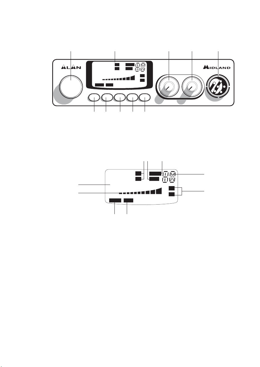
FUNCTION AND LOCATION OF THE CONTROLS
1. Channel selector
2. Multifunction backlighted display.It shows:
A. Channel selected number
B. The received signal strength and the power of the transmitting signal
C. AM/FM mode
D. RX/TX:TX=transmit mode; RX=receive mode
E. SCAN mode
F. EMG mode
G.Frequency band selected.
H.LOW: displayed when the radio transmits in low power (this mode is possible with
some frequency bands only – see the Frequency band chart).
I. LOCK: microphone (UP/DOWN buttons) lock enabled.
3. ”EMG” button: Emergency channel. By pressing it, you will be automatically positio-
ned on CH 9 (emergency channel). The display will show “EMG”. It will not be possibile to change accidentally the channel.
4. 5.“Q.UP/Q.DOWN” buttons: To skip 10 channels UP (Q. UP) or 10 channels DOWN
(Q.DOWN).
2
78 PLUS MULTI
CHANNEL
EMG Q.UP Q.DOWN AM/FM SCAN
SQUELCH ON/OFF VOL
MICON/OFF
3 4 5 6 7
9 1021 8
88
CH
5
9
+30
SIG
0.5
123 4PWR
FM
AM
LOW
SCAN
EMGLOCK
TX
RX
LCR
1
3
88
CH
1
3
5
9
+30
SIG
0.5
123 4PWR
FM
AM
LOW
SCAN
EMGLOCK
TX
RX
A
CE
G
D
FI
B
H
Page 9
ENGLISH
6. “AM/FM”(LCR) button: To select AM or FM mode. If you switch on the unit and push
“AM/FM”(LCR) and “SCAN” at the same time, you will select the operating band,
which will be visualised on the displayed.
If you select a frequency band operating in FM mode only, this button enables the LCR
function (Last Channel Recall).
7. "SCAN" button: With this control, you can automatically seek for a busy channel.
Turn the Squelch clockwise until the background noise is no longer heard.
Press the "SCAN" button: the transceiver will scan automatically all the channels until
a carrier is being received. If you switch on the unit and push “SCAN” and
“AM/FM”(LCR) at the same time, you will select the operating band, which will be
visualised on the displayed.
8. "Squelch" Control: For the maximum receiver sensitivity, the control must be regula-
ted exactly where the receiver background noise disappears.
9. “ON/OFF Volume” Control. In "OFF" position your transceiver is OFF. Turn this control
clockwise to switch on the unit. Turn the knob clockwise a little more to set the audio
level, until you get a comfortable reception.
10. Microphone jack: Insert the mic connector into this jack.
REAR PANEL
11. ”EXT” jack: external loudspeaker jack.(the internal loudspeaker is excluded)
12. Power 13.8V DC: power supply cable
13. S.Meter jack: it allows an external “S. Meter” connection
14. Antenna connector (SO239 connector type)
3
EXT
S. METER
DC
13,8V
ANTENNA
11
12
13 14
Page 10

MICROPHONE
1. PTT: transmission button
2. UP/DOWN buttons: manual channels selector.
3. LOCK button: it allows you to lock the UP/DOWN buttons.
4. 6 pin microphone connector
INSTALLATION
Safety and convenience are the primary consideration for mounting any piece of mobile
equipment. All controls must readily available to the operator without interfering with the
movements necessary for safe operation of the vehicle. Set the proper position in the car
to install the transceiver using the supplied supporting bracket or eventually the slide bracket. Tighten the retaining screws. The fixing bracket must be close to metallic parts.
POWER SUPPLY
Be sure the transceiver is OFF. In the direct-voltage power supply, is very important to
observe the polarity even if the unit is protected against the accidental inversion:
Red = positive pole (+)
Black = negative pole (-)
The same colors are present on the battery and in the fuse box of the car. Correctly connect the cable terminal to the battery.
INSTALLING AN ANTENNA
1. Place the antenna as high as possible
2. The longer the antenna, the better will be the performance
3. If possible, mount the antenna in the center of whatever surface you choose
4. Keep antenna cable away from noise sources, such as the ignition switch, gauges,etc.
5. Make sure you have a solid metal-to-metal ground connection.
6. Prevent cable damage during antenna installation.
WARNING: To avoid damage, never operate your CB radio without connecting a proper
antenna. A periodical control of the cable and of the S.W.R. is recommended.
4
4
2
1
3
Page 11
ENGLISH
HOW TO OPERATE WITH YOUR TRANSCEIVER
1. Screw the microphone plug into the microphone jack.
2. Make sure your antenna is securely connected to the antenna connector.
3. Make sure the SQUELCH control is turned fully conterclockwise.
4. Turn on the unit and adjust the volume control.
5. Select your desired channel.
6. To transmit, press the PTT button and speak in a normal tone of voice.
7. To receive, release the PTT button.
FREQUENCY BAND SELECTION
The frequency bands must be chosen according to the country where you are going to
operate.
Procedure:
Switch off the unit.
Turn it on while pushing the “AM/FM” e “SCAN” buttons at the same time.
Rotate the “CHANNEL” knob and select the desired frequency band (see the chart here
below).
To stop your selection, press the “AM/FM” button.
NOTE
1
: In the UK frequency band, you can select directly the EC band by pushing the
“AM/FM” button for 2 seconds.
NOTE
2
: If you select a frequency band which operates in FM mode only, the “AM/FM” con-
trol enables the LCR function (last channel recall).
FREQUENCY BAND CHART
Digits Country
displayed
I Italy 40 CH AM/FM 4Watt
I2 Italy 34 CH AM/FM 4Watt
D Germany 80 CH FM 4Watt / 12 CH AM 1Watt
D2 Germany 40 CH FM 4Watt / 12 CH AM 1Watt
EU Europe 40 CH FM 4Watt / 40 CH AM 1Watt
EC CEPT 40 CH FM 4Watt
E Spain 40 CH AM/FM 4Watt
F France 40 CH FM 4Watt / 40 CH AM 1Watt
UK England 40 CH FM 4 Watt English frequencies + EC 40 CH FM 4Watt
CEPT frequencies
ATTENTION!
The frequency band definitely allowed all over Europe is 40 CH FM 4W (EC).
5
Page 12

TECHNICAL SPECIFICATIONS
GENERAL
Channels ................................................................40 FM (see the frequency band chart)
Frequency Range ..............................................................................25.615 to 30.105 MHz
Frequency Control ..........................................................................................................PLL
Operating Temperature Range ..........................................................................-10°/+55° C
DC input voltage ........................................................................................13.8V DC ±15%
Size ..........................................................................................180 (L)x35 (H)x140 (P) mm
Weight......................................................................................................................0,850 kg
RECEIVER
Receiving system ..........................................................dual conversion superheterodyne
Intermediate frequency ................................................I° IF: 10.695 MHz • II° IF: 455 KHz
Sensitivity....................................................................0.5µV for 20 dB SINAD in FM mode
....................................................................................0.5µV for 20 dB SINAD in AM mode
Audio output power @10% THD ................................................................2.0 W @ 8 Ohm
Audio distortion................................................................................less than 8% @ 1 KHz
Image rejection ............................................................................................................65 dB
Adjacent channel rejection ..........................................................................................65 dB
Signal/Noise ratio ........................................................................................................45 dB
Current drain at stand/by ..........................................................................................250mA
TRANSMITTER
Output power....................................................................duty cycle 10% 4W @ 13.8V DC
Modulation........................................................................................AM: from 85% to 95%
..........................................................................................................FM: 1,8 KHz ± 0,2 KHz
Frequency response ........................................................................from 400 Hz to 2.5 KHz
Output impedance ..........................................................................RF 50 Ohm unbalanced
Signal/Noise Ratio................................................................................................40 dB MIN
Current drain..............................................1100mA (Power position with no modulation)
All specifications are subject to change without notice.
6
Page 13

FRANÇAIS
Sommaire
Introduction Pag.1
Fonctions et controles Pag.2
Installation Pag.4
Alimentation Pag.4
Installation de l'antenne Pag.4
Utilisation de l’Alan 78 Plus Multi Pag.5
Sélection des bandes de fréquence Pag.5
Tableau des bandes de fréquence Pag.5
Specifications techniques Pag.6
Vous venez d’acquérir un équipement Emetteur Récepteur CB équipé de composants
modernes au sommet de la technologie.
C’est une belle réalisation utilisant des composants de qualité dans un boîtier robuste.
L’utilisation de composants miniatures montés en surfaces (CMS) garanti un fonctionnement fiable de longue durée.
Votre équipement CB est équipé d’un synthétiseur de fréquence permettant le balayage
rapide des tous les canaux, une grande précision des fréquences et une excellente pureté
d’émission.
1
Page 14
FONCTIONS ET CONTROLES
1. Sélection des canaux.
2. Afficheur multifonctions. Il visualise:
A.Le numéro du canal utilisé.
B.Le niveau relatif du signal reçu avec la puissance émise.
C.Le mode de fonctionnement FM ou AM.
D.RX : Réception, TX : Emission.
E. Le mode de balayage (SCAN).
F. Le canal de sécurité (EMG).
G.Indique la bande de fréquence sélectionnée.
H.LOW: est visualisé quand la radio transmet en basse puissance (cette condition se
vérifie seulement pour certaines bandes de fréquence – voir le tableau).
I. LOCK: Blocage du clavier du microphone (UP/DOWN) activé.
3. Le bouton EMG L’appui sur ce bouton sélectionne immédiatement le canal 9 utilisé
pour l’urgence et la sécurité. L’afficheur indique «EMG». Il n’est pas possible de modi-
fier accidentellement le canal. Supprimer la fonction «EMG» pour changer le
canal.
4.5.Les boutons Q.UP et Q.DOWN Ces boutons permettent de modifier les canaux par
dizaine.
2
78 PLUS MULTI
CHANNEL
EMG Q.UP Q.DOWN AM/FM SCAN
SQUELCH ON/OFF VOL
MICON/OFF
3 4 5 6 7
9 1021 8
88
CH
5
9
+30
SIG
0.5
123 4PWR
FM
AM
LOW
SCAN
EMGLOCK
TX
RX
LCR
1
3
88
CH
1
3
5
9
+30
SIG
0.5
123 4PWR
FM
AM
LOW
SCAN
EMGLOCK
TX
RX
A
CE
G
D
FI
B
H
Page 15

FRANÇAIS
6. Bouton “AM/FM” (LCR): Pour sélectionner le mode AM ou FM. Si vous l’appuyez avec
le bouton “SCAN” quand vous allumez l’émetteur, “AM/FM” sélectionne la bande operative. Votre choix sera visualisée sur l’écran.
Si vous sélectionnez une bande de fréquence seulement en modalité FM, cette touche
active la fonction LCR (rappeler le dernier canal utilisé).
7. Bouton SCAN. Ce bouton permet le balayage automatique des 40 canaux de la bande.
Si vous l’appuyez avec le bouton “AM/FM”, quand vous allumez l’émetteur, “SCAN”
sélectionne la bande operative. Votre choix sera visualisée sur l’écran.
NOTE : Il est impératif que le bouton de Squelch ou silencieux soit lentement tourné
dans le sens horaire à la limite ou le bruit disparaît du haut parleur en l’absence de
réception utile.
8. SQUELCH ou SILENCIEUX A régler comme ci-dessus.
9. ON/OFF VOLUME Ce bouton cumule les fonctions d’arrêt-marche général de
l’équipement ainsi que le réglage de volume d’écoute sur haut parleur. Embase pour
connections du microphone.
PANNEAU ARRIERE
11. EXT: Cette embase JACK 3,5 mm permet le raccordement d’un haut parleur extérieur.
12. Câble d’alimentation 13,8 Vcc.
13. S. Meter: Cette embase JACK 2,5 mm permet le raccordement d’un instrument de
mesure
affichant le niveau du signal reçu.
3
EXT
S. METER
DC
13,8V
ANTENNA
11
12
13 14
Page 16

14. Connecteur Antenne (SO239 pour PL239).
MICROPHONE
1. PTT: bouton pour l’émission.
2. UP/DOWN: boutons de changement de canal.
3. Touche LOCK: permet le blocage des touches
UP/DOWN du microphone.
4. Fiche de raccordement du microphone.
INSTALLATION
Sécurité et montage aisé doivent guider toute l’installation. Tous les contrôles doivent être
accessibles à l’opérateur sans provoquer de mouvements pouvant mettre en danger le
conduite du véhicule. Sélectionner la meilleure position pour l’équipement afin d’allier discrétion et sécurité. Utiliser l’étrier de montage livré avec l’équipement. Bien fixer l’équipement.
ALIMENTATION
S’assurer que l’appareil est arrêté (position OFF).
Vérifier la polarité du câble d’alimentation :
* Le fil rouge doit être relié à la borne positive +
* Le fil noir doit être relié à la borne négative -.
Les dégâts éventuels provoqués par un mauvais câblage ne sont pas couverts par la garantie.
INSTALLATION DE L’ANTENNE
Le rendement de votre installation est totalement lié à la qualité de l’antenne utilisée.
Respecter les règles suivantes:
1. Placer l’antenne le plus haut possible.
2. La longueur de l’antenne doit être la plus importante possible.
3. Si possible centrer l’antenne sur une surface métallique plane.
4. Eloigner le plus possible le câble de l’antenne des sources d’interférences du véhicule
(alternateur, bobines, calculateurs, etc.)
5. Assurer un excellent contact de la masse de votre antenne avec la masse du véhicule.
6. Contrôler soigneusement le passage du câble d’antenne. Eviter les courbures trop rai-
4
4
2
1
3
Page 17

FRANÇAIS
des qui pourraient le blesser.
ATTENTION: il est recommandé de contrôler régulièrement la qualité de votre installation
d’antenne si possible à l’aide d’un Wattmètre TOS mètre
UTILISATION DE L’ALAN 78 PLUS MULTI
Une fois l’installation réalisée :
1 Connecter votre microphone,
2 Régler le silencieux (Squelch),
3 Règler l’appareil et régler le volume en position médiane,
4 Sélectionner le canal désiré,
5 Pour émettre appuyer sur le PTT du micro et parler normalement à 10 cm du micro.
6 Pour écouter, relâcher le PTT.
SELECTION DES BANDES DE FREQUENCE
Les bandes de fréquence doivent être choisies selon le pays ou vous voulez opérer.
1. Eteignez l’appareil.
2. Allumez la radio et appuyez dans le même temps les touches “AM/FM” et “SCAN”.
3. Avec le commande “CHANNEL”, sélectionnez la bande de fréquence désirée (voir le
tableau des bandes de fréquence).
4. Appuyez le bouton “AM/FM” pour terminer la sélection.
NOTE
1
: dans la bande de fréquence UK, c’est possible de sélectionner directement la
bande EC en appuyant la touche “AM/FM” pour 2 secondes environ.
NOTE
2
: Quand vous sélectionnez une bande de fréquence seulement en modalité FM, la
touche “AM/FM” active la fonction LCR (rappeler le dernier canal utilisé).
TABLEAU DES BANDES DE FREQUENCE
Sigle Pays
sur l’écran
I Italie 40 CH AM/FM 4Watt
I2 Italie 34 CH AM/FM 4Watt
D Allemagne 80 CH FM 4Watt / 12 CH AM 1Watt
D2 Allemagne 40 CH FM 4Watt / 12 CH AM 1Watt
EU Europe 40 CH FM 4Watt / 40 CH AM 1Watt
EC CEPT 40 CH FM 4Watt
E Espagne 40 CH AM/FM 4Watt
F France 40 CH FM 4Watt / 40 CH AM 1Watt
UK Angleterre 40 CH FM 4 Watt fréquences anglaises + EC 40 CH FM 4Watt
fréquences CEPT
ATTENTION!
La bande de fréquences reconnue sûrement dans tous les pays européens est 40CH FM
4W (EC) - voir le tableau pour les réstrictions à l’usage.
5
Page 18

SPECIFICATIONS TECHNIQUES
GENERALITES
Canaux .............................................. 40 FM (voir le tableau des bandes de fréquences)
Bande de fréquence ..........................................................................25.615 à 30.105 Mhz
Générateur de fréquence ..........................................................................par synthétiseur
Température d’utilisation ..................................................................................-1O°/+55°C
Tension d’alimentation ..........................................................................13,8 V DC+/- 15 %
Dimensions ..........................................................................................180 x 35 x 140 mm
Poids......................................................................................................................0,850 kg
RECEPTEUR
Système de réception ............................................Superhétérodyne à double conversion
Fréquence intermédiaire........................................................1er 10,695 Mhz. 2è 455 Khz
Sensibilité ..................................................................0,5 µv pour 20 dB SINAD AM et FM
Puissance audio ..........................................................................................2 W @ 8 Ohms
Distorsion ....................................................................................Mieux que 8 % @ 1 Khz
Réjection image..........................................................................................................65 dB
Réjection canal adjacent..............................................................................................65dB
Consommation........................................................................................................250 mA
EMETTEUR
Puissance........................................................................duty cycle 10% 4 W @ 13,8 VCC
Modulation........................................................................................FM 1,8 KHz ± 0,2 KHz
Bande audio..............................................................................................400 Hz à 2,5 Khz
Impédance antenne ..............................................................................................50 Ohms
Consommation............................................................................1,100 A sans modulation
Spécifications pouvant être modifiées sans préavis.
6
Page 19

DEUTSCH
INHALT
Einführung Seite 1
Funktion und Lage der Bedienelemente Seite 2
Einbau des ALAN 78 PLUS MULTI im Kraftfahrzeug Seite 4
Anschluß an die Spannungsversorgung Seite 4
Montage der Antenne Seite 4
Bedienung Ihres ALAN 78 PLUS MULTI Seite 5
Auswahl der Frequenzbänder Seite 5
Frequenztabelle Seite 5
Technische Daten Seite 6
Ihr CB-Mobilfunkgerät ALAN 78 PLUS MULTI verkörpert den aktuellen Stand der Entwicklung auf
dem Gebiet der Funkgerätetechnik. Dank der kompakten Abmessungen und der kompromißlosen
Auslegung für den Mobilbetrieb wird die besondere Leistungsfähigkeit auf allen CB-Kanälen
sichergestellt. Sie haben ein elektronisches Qualitätsprodukt vor sich, das professionell konstruiert und mittels ausgesuchter, erstklassiger Komponenten gebaut worden ist. Eine leistungsfähige Halbleitertechnik mit aktueller PLL-Schaltung ermöglicht durch ihre hohe
Frequenzkonstanz und dem Aufbau auf einer stabilen Leiterplatte einen jahrelang störungsfreien
Betrieb Ihres Gerätes.
1
Page 20

FUNKTION UND LAGE DER BEDIENELEMENTE
1. Kanalwahlschalter: mit diesem Schalter lassen sich die Kanäle einstellen.
2. Multifunktions-Display mit Hintergrundbeleuchtung. Im Display werden die folgenden
Informationen angezeigt:
A. Zweistellige Kanalanzeige
B. Relative Empfangsfeldstärke und Sendeleistung
C. AM/FM-Betriebsart
D.RX-/TX-Anzeige: TX = Sendebetrieb, RX = Empfangsbetrieb
E. SCAN-Betrieb, Suchlauf nach belegten Kanälen
F. EMG-Kanal, Fernfahrer-/Notruf-Kanal
G. Zeigt das gewählte Frequenzband an.
H. LOW: erscheint, wenn das Funkgerät auf niedrige Ausgangsleistung schaltet (betrifft nur
bestimmte Frequenzbänder – siehe Frequenztabelle)
I. LOCK: Aktivierung der Mikrofon-Tastaturverriegelung (UP/DOWN).
3. Kanal 9 Direkttaste, EMG: Auf Knopfdruck läßt sich der Notrufkanal 9 direkt einschalten. In
der Anzeige erscheint der Schriftzug “EMG”. Ein anderer Kanal läßt sich nicht einstellen,
solange der EMG-Kanal aktiv ist.
4. 5. 10-Kanal-Tasten, Q.UP und Q.DOWN: Drücken der Q. UP-Taste schaltet 10 Kanäle höher, Q.
DOWN schaltet 10 Kanäle tiefer.
2
78 PLUS MULTI
CHANNEL
EMG Q.UP Q.DOWN AM/FM SCAN
SQUELCH ON/OFF VOL
MICON/OFF
3 4 5 6 7
9 1021 8
88
CH
5
9
+30
SIG
0.5
123 4PWR
FM
AM
LOW
SCAN
EMGLOCK
TX
RX
LCR
1
3
88
CH
1
3
5
9
+30
SIG
0.5
123 4PWR
FM
AM
LOW
SCAN
EMGLOCK
TX
RX
A
CE
G
D
FI
B
H
Page 21

DEUTSCH
6. Taste “AM/FM” (LCR): Zur Auswahl der gewünschten Betriebsart (AM/FM). Hält man beim
Einschalten die Tasten “AM/FM” und “SCAN” gleichzeitig gedrückt, kommt man in die
Frequenzbandauswahl. Die entsprechende Wahl wird im Display angezeigt.
Wird ein Frequenzband gewählt, das nur in der Betriebsart FM arbeitet, übernimmt die Taste
“AM/FM” statt der Betriebsartwahl die LCR-Funktion (Last Channel Recall – Aufruf des zuletzt
genutzten Kanals).
7. Suchlauftaste, SCAN: Durch Einschalten des Suchlaufbetriebs lassen sich belegte Kanäle
automatisch suchen. Dazu muß die Rauschsperre so aktiviert sein, daß das
Hintergrundrauschen unterdrückt wird. Drücken der Scan-Taste startet den Suchlauf. Der
Suchlauf stoppt, sobald ein belegter Kanal gefunden ist. Hält man beim Einschalten die Tasten
“AM/FM” und “SCAN” gleichzeitig gedrückt, kommt man in die Frequenzbandauswahl. Die
entsprechende Wahl wird im Display angezeigt.
8. Rauschsperre, Squelch: Um die höchstmögliche Empfangsempfindlichkeit zu nutzen, muß
der Regler so eingestellt werden, daß das Hintergrundrauschen gerade unterdrückt wird.
9. Ein/Aus-Schalter, Lautstärkeregler: In der Stellung “OFF” ist Ihr ALAN 78 PLUS MULTI
ausgeschaltet. Durch Drehen des Reglers im Uhrzeigersinn wird das Gerät eingeschaltet.
Weiteres Drehen im Uhrzeigersinn erhöht die Wiedergabelautstärke nach Wunsch.
10. Mikrofonbuchse: Hier wird der Stecker des Mikrofons eingesteckt.
GERÄTERÜCKSEITE
11. Anschluß für externen Lautsprecher, EXT: An diese Buchse kann ein externer
Wiedergabelautsprecher angeschlossen werden. Der eingebaute Lautsprecher schaltet sich
dann automatisch ab.
12. Buchse zum Anschluß der Spannungsversorgung, Power 13.8 V: über diese Buchse wird
das 12 V Anschlußkabel mit dem Gerät verbunden.
13. S-Meter-Anschluß, S. Meter: An diese Buchse kann ein externes S-Meter angeschlossen
werden.
14. Antennenbuchse (SO 239): Hier wird der Stecker des Antennenkabels mit dem ALAN 78
PLUS MULTI verbunden.
3
EXT
S. METER
DC
13,8V
ANTENNA
11
12
13 14
Page 22

MIKROFON
1. PTT: Taste zur Sende-/Empfangsumschaltung
2. UP-/DOWN-Tasten: Kanalwahltasten
3. Taste LOCK: Verriegelung der Tasten UP/DOWN am
Mikrofon
4. 6-poliger Mikrofonanschluß
EINBAU DES ALAN 78 PLUS MULTI
IM KRAFTFAHRZEUG
Einfache Bedienbarkeit ohne Beeinträchtigung der Verkehrssicherheit sollte beim Fahrzeugeinbau
im Vordergrund stehen. Suchen Sie eine geeignete Einbauposition in Ihrem Fahrzeug und bauen
Sie Ihr ALAN 78 PLUS MULTI mit Hilfe des Halte-bügels allein oder unter Verwendung der
Führungsschienen ein. Der Haltebügel sollte möglichst Verbindung mit Metallteilen der
Karosserie haben.
ANSCHLUß AN DIE SPANNUNGSVERSORGUNG
Stellen Sie zunächst sicher, daß Ihr ALAN 78 PLUS MULTI ausgeschaltet ist. Es ist ganz wichtig,
daß Sie den Anschluß des Stromkabels polaritätsrichtig vornehmen. Dies gilt auch dann, wenn
Ihr Gerät gegen mögliche Verpolung geschützt ist:
Rote Kabelader = Pluspol (+)
Schwarze Kabelader = Minuspol (-)
Die gleichen Farben finden Sie an den Batteriepolen und manchmal auch im Sicherungskasten
Ihres Fahrzeugs. Schließen Sie die Kabelenden besonders sorgfältig an die Stromversorgung des
Fahrzeugs an.
MONTAGE DER ANTENNE
1. Wählen Sie den Antennenstandort so hoch wie möglich.
2. Je größer die mechanische Länge der Antenne ist, desto besser wird die Leistung sein.
3. Falls möglich, montieren Sie die Antenne in der Mitte der gewählten Montagefläche.
4. Verlegen Sie das Antennenkabel möglichst weit entfernt von störenden Aggregaten (Zündung,
elektrischen Verbrauchern usw.).
5. Stellen Sie sicher, daß metallisch leitende Teile des Antennenfußes einen möglichst großflächigen Kontakt zum metallisch blanken Karosserieblech haben.
6. Achten Sie darauf, daß das Antennenkabel bei der Montage nicht beschädigt wird und sich
durch Vibrationen im Fahrbetrieb nicht durchscheuern kann.
WARNUNG!:
Um Schäden zu vermeiden, sollten Sie Ihr ALAN 78 PLUS MULTI niemals ohne geeignete CBAntenne betreiben. Darüber hinaus empfehlen wir Ihnen, das Antennenkabel sowie das
Stehwellenverhältnis (SWR) in regelmäßigen Abständen zu überprüfen.
4
4
2
1
3
Page 23

DEUTSCH
BEDIENUNG IHRES ALAN 78 PLUS MULTI
1. Stecken Sie den Mikrofonstecker in die Mikrofonbuchse Ihres ALAN 78 PLUS MULTI.
2. Stellen Sie sicher, daß Ihre Funkantenne über das Antennenkabel fest und sicher mit dem
Antennenanschluß Ihres ALAN 78 PLUS MULTI verbunden ist.
3. Vergewissern Sie sich, daß die Rauschsperre (Squelch) geöffnet ist, d. h. der Regler bis zum
Anschlag gegen den Uhrzeigersinn gedreht ist.
4. Schalten Sie Ihr ALAN 78 PLUS MULTI ein und stellen Sie die Wiedergabelautstärke nach Ihren
persönlichen Wünschen ein.
5. Stellen Sie den gewünschten Funkkanal ein.
6. Zum Senden drücken Sie die PTT-Taste und besprechen das Mikrofon mit normaler Lautstärke
und Tonlage.
7. Zum Empfangen lassen Sie einfach die PTT-Taste wieder los.
AUSWAHL DER FREQUENZBÄNDER
Bei der Auswahl der Frequenzbänder sind die Vorschriften der Länder zu beachten, in denen das
Funkgerät betrieben wird.
Vorgehensweise:
1. Schalten Sie das Funkgerät aus.
2. Schalten Sie das Funkgerät wieder ein und halten Sie dabei gleichzeitig die Tasten „AM/FM“ und
„SCAN“ gedrückt.
3. Drehen Sie den Kanalwahlschalter “CHANNEL” und wählen Sie das gewünschte Frequenzband
aus (siehe Frequenzbandtabelle).
4. Drücken Sie die Taste “AM/FM”, um die Auswahl zu bestätigen.
NOTIZ
1
: Auf dem Frequenzband UK besteht die Möglichkeit das Frequenzband EC (CEPT) direkt
auszuwählen. Halten Sie dazu die Taste “AM/FM” ca. zwei Sekunden gedrückt.
NOTIZ2: Wird ein Frequenzband gewählt, das nur in der Betriebsart FM arbeitet, übernimmt die
Taste “AM/FM” statt der Betriebsartwahl die LCR-Funktion (Last Channel Recall – Aufruf
des zuletzt genutzten Kanals).
FREQUENZTABELLE
Anzeige Land
im Display
I Italien 40 Kanäle AM/FM 4 Watt
I2 Italien 34 Kanäle AM/FM 4 Watt
D Deutschland 80 Kanäle FM 4 Watt / 12 Kanäle AM 1 Watt
D2 Deutschland 40 Kanäle FM 4 Watt / 12 Kanäle AM 1 Watt
EU Europa 40 Kanäle FM 4 Watt / 40 Kanäle AM 1 Watt
EC CEPT 40 Kanäle FM 4 Watt
E Spanien 40 Kanäle AM/FM 4 Watt
F Frankreich 40 Kanäle FM 4 Watt / 40 Kanäle AM 1 Watt
UK England 40 Kanäle FM 4 Watt Englische Frequenzen + EC 40 Kanäle FM
4 Watt CEPT Frequenzen
ZULASSUNG: Das Alan 78 PLUS MULTI ist entsprechend den europäischen Bestimmungen in
5
Page 24

allen Ländern notifiziert, die die europäische R&TTE Direktive anwenden und darf entsprechend
den landesüblichen Bestimmungen benutzt werden. In Deutschland ist für den Betrieb in den
Programmierstellungen D (80/12 Kanäle) EU (40/40 Kanäle) und D 2 (40/12 Kanäle) eine
Anmeldung und eine "Einzelzuteilung" bei der zuständigen RegTP Aussenstelle erforderlich.
Zum Zeitpunkt der Drucklegung dieser Anleitung werden dafür regelmässige Gebühren erhoben.
Der Betrieb in der Programmierstellung EC ist in Deutschland und in den meisten europäischen
Ländern für Reisende anmelde-und gebührenfrei.
TECHNISCHE DATEN
Allgemeine Daten
Kanäle ......................................................................................40 FM (siehe die Frequenztabelle)
Frequenzbereich..............................................................................................25.615 - 30.105 MHz
Frequenzerzeugung ......................................................................................................PLL-System
Betriebstemperatur....................................................................................................10° C - +55° C
Spannungsversorgung..............................................................................nom. 13,8 V DC +/- 15%
Abmessungen..........................................................................................180x35x140 mm (BxHxT)
Gewicht................................................................................................................................0,850 kg
Empfänger
Empfangsprinzip ..........................................................................................................Doppelsuper
Zwischenfrequenzen................................................................1. ZF: 10,695 MHz • 2. ZF: 455 kHz
Empfindlichkeit ........................................................................................0,5 µV bei 20 dB SINAD
NF-Wiedergabeleistung..........................................................................2 W an 8 Ohm, 10 % Klirr
Wiedergabeverzerrungen........................................................................weniger als 8% bei 1 kHz
Spiegelfrequenzunterdrückung................................................................................................65 dB
Nachbarkanaldämpfung ..........................................................................................................65 dB
Geräuschspannungsabstand ..................................................................................................45 dB
Ruhestromaufnahme............................................................................................................250 mA
Sender
Sendeleistung ............................................................................duty cycle 10% 4 W bei 13,8 Vdc
Modulation..............................................................FM: 1,8 kHz +/-200 Hz AM: von 85% bis 95%
Sendefrequenzgang................................................................................................400 Hz - 2,5 kHz
Ausgangsimpedanz (HF) ..........................................................................50 Ohm, unsymmetrisch
Geräuschspannungsabstand ........................................................................................mind. 40 dB
Stromaufnahme ........................................................................................................................1,1 A
Die Änderung der Technischen Daten ohne vorherige Ankündigung im Zuge der
Weiterentwicklung bleibt vorbehalten.
6
Page 25

ESPAÑOL
INDICE
Introducción Pag. 1
Funciones y posicion de los controles Pag. 2
Instalacion Pag. 4
Alimentacion Pag. 4
Instalacion de la antena Pag. 4
Funcionamiento del transceptor Pag. 5
Selección de la banda de frequencias Pag. 5
Tabla de bandas disponibles Pag. 5
Especificaciones Pag. 6
El ALAN 78 PLUS MULTI representa el máximo exponente en la nueva generación de equipos CB al
haberse utilizado en su diseño y producción la más avanzada tecnología en ingeniería electrónica.
Dotado de todos los controles y funciones necesarios para satisfacer al más exigente de los radioaficionados, la calidad de los materiales empleados en su fabricación así como su versatilidad y funcionalidad le harán disfrutar de excelentes momentos de radio a la vez que generará una sana envidia entre sus colegas.
El ALAN 78 PLUS MULTI es un equipo electrónico de alta calidad, construido con los mejores componentes. La circuitería es de estado sólido montada sobre robustas placas de circuito impreso. Su
diseño le permitirá trabajar con esta unidad durante muchos años, sin merma alguna en sus prestaciones.
El moderno circuito PLL utiliza una nueva técnica para generar todas la gama de frecuencias requerida con un mínimo de cristales. El resultado es un control más eficiente de la frecuencia y una fiabilidad insuperable.
Estamos convencidos de que acaba de adquirir uno de los mejores equipos CB que existen en el mercado. Disfrútelo muchos años.
1
Page 26

FUNCIONES Y POSICION DE LOS CONTROLES
1. Selector de canales
2. Pantalla retroiluminada multifunción. Muestra:
A. El número del canal seleccionado.
B. La intensidad de la señal recibida y la potencia de la señal transmitida.
C. Modo AM/FM
D.RX / TX: TX = modo de transmisión; RX = modo de recepción
E. Modo de exploración (SCAN)
F. Modo de emergencia (EMG)
G.Indica la banda de frecuencias seleccionada (véase tabla de bandas disponibles)
H.LOW: se visualiza cuando la radio transmite con baja potencia (condición que se da sólo en
determinadas bandas de frecuencia – véase tabla de bandas)
I. LOCK: teclado (UP/DOWN) del micrófono bloqueado
3. Botón EMG: Canal de emergencia. Pulse este botón para posicionarse automáticamente en el CH
9 (canal de emergencia). La pantalla muestra "EMG". Con esta función activada, el selector de
canales queda inhabilitado.
4-5.Botones Q,UP/Q.DOWN: Para saltar rápidamente 10 canales hacia arriba (Q.UP) o 10 canales
hacia abajo (Q.DOWN).
6. Botón AM/FM (LCR): Sirve para seleccionar el tipo de modulación deseada: AM o FM. Si mien-
tras se enciende el equipo se pulsa juntamente con la tecla “SCAN”, selecciona la banda operativa. La selección se visualizará en el display.
2
78 PLUS MULTI
CHANNEL
EMG Q.UP Q.DOWN AM/FM SCAN
SQUELCH ON/OFF VOL
MICON/OFF
3 4 5 6 7
9 1021 8
88
CH
5
9
+30
SIG
0.5
123 4PWR
FM
AM
LOW
SCAN
EMGLOCK
TX
RX
LCR
1
3
88
CH
1
3
5
9
+30
SIG
0.5
123 4PWR
FM
AM
LOW
SCAN
EMGLOCK
TX
RX
A
CE
G
D
FI
B
H
Page 27

Si selecciona una banda de frecuencia que opera sólo en modo FM, la tecla “AM/FM” activa la función LCR (llamada del último canal seleccionado)
7. Botón SCAN (exploración): Con esta función activada el equipo busca automáticamente los canales
ocupados.
Gire hacia la derecha el botón del silenciador (SQUELCH) hasta que desaparezca el ruido de fondo.
Pulse el botón SCAN: el transceptor efectuará el barrido automático de todos los canales hasta que
en alguno de ellos encuentre una señal. Tres 3 segundos después del cese de ésta, el equipo reanudará automáticamente la exploración.
Si desea detenerla, pulse el PTT.
Si mientras se enciende el equipo se pulsa juntamente con la tecla “AM/FM”, selecciona la banda
operativa. La selección se visualizará en el display
8. Control SQUELCH (silenciador): Para obtener la máxima sensibilidad del receptor, este control debe
regularse exactamente en el punto en que desaparece el ruido de fondo.
9. Control ON/OFF Volume (encendido y volumen): En la posición OFF el transceptor está apagado.
Gire este control hacia la derecha para encender la unidad. Gírelo todavía un poco más hacia la derecha para alcanzar el nivel de audio deseado. Con el selector PA-CB en la posición PA, el botón controla el nivel de salida de audio.
10. Toma para el micrófono: Inserte el conector del micrófono.
PANEL POSTERIOR
11. Jack EXT: para la conexión de un altavoz externo (al conectar el altavoz externo, el interno queda
desactivado.
12. Power 13.8 VCC: Entrada de alimentación.
13. Jack S.Meter: Permite la conexión de un medidor de señal externo.
14. Conector de antena: (Conector tipo SO239).
3
ESPAÑOL
EXT
S. METER
DC
13,8V
ANTENNA
11
12
13 14
Page 28

MICROFONO
1. PTT: botón de transmisión
2. Pulsadores UP/DOWN: Selector manual de canales.
3. Tecla LOCK: permite bloquear los pulsadores UP/DOWN del
micrófono
4. Conector del micrófono de 6 pines
INSTALACION
La seguridad y la facilidad son las consideraciones primordiales para efectuar el montaje de cualquier
equipo móvil. Todos los controles deben ser fácilmente accesible al operador, sin que ello interfiera en
la correcta conducción del vehículo. Seleccione la posición adecuada del vehículo donde instalar el transceptor y use el soporte suministrado o eventualmente un soporte deslizante (opcional). Coloque los tornillos de retención. El soporte de fijación debe estar en contacto con las partes metálicas.
Atención: le recordamos que está totalmente prohibido utilizar micrófonos de mano en las comunicaciones móviles (en vehículos). Existe a su dispoción un “kit manos libres” original ALAN que le permitirá utilizar la radio sin necesidad de apartar las manos del volante, manteniendo las prestaciones del equipo y aumentando considerablemente tanto su seguridad como la del resto de conductores.
ALIMENTACION
Asegúrese de que el transceptor está apagado. En la alimentación de corriente continua es muy importante observar la polaridad incluso si la unidad está protegida contra una inversión accidental:
Rojo = polo positivo (+); Negro = polo negativo (-)
Los mismos colores se encuentran presentes en la batería y en la caja de fusibles del vehículo. Conecte
correctamente el terminal del cable a la batería.
INSTALACION DE LA ANTENA
1. Instale la antena lo más alta posible.
2. Cuanto más larga sea la antena, mejores prestaciones obtendrá.
3. Si es posible, monte la antena en el centro de la superficie escogida.
4. Mantenga el cable de antena a resguardo de fuentes de ruido, tales como el encendido del coche, etc.
5. Asegúrese de que dispone de una sólida conexión a masa metal a metal.
6. Evite que se dañe el cable durante la instalación de la antena.
Advertencia: Para evitar provocar daños, nunca opere su radio sin que esté conectada a una antena adecuada. Se recomienda un control periódico del cable y de las ROE.
4
4
2
1
3
Page 29

ESPAÑOL
FUNCIONAMIENTO DEL TRANSCEPTOR
1. Enchufe el micrófono en el jack correspondiente.
2. Asegúrese de que la antena esté conectada al equipo.
3. Verifique que el control del silenciador esté girado completamente hacia la izquierda.
4. Encienda la unidad y ajuste el control de volumen.
5. Seleccione el canal deseado.
6. En ausencia de señal, ajúste el silenciador (squelch) para eliminar el ruído de fondo.
7. Para transmitir, pulse el botón PTT y hable a unos 10cm del micrófono i con un tono de voz normal.
8. Para recibir, libere el botón PTT.
SELECCIÓN DE LA BANDA DE FRECUENCIAS
La selección de la banda de frecuencias debe ser acorde al país de uso del equipo.
Procedimiento:
a) Apague el equipo
b) Enciéndalo mientras pulsa las teclas “AM/FM” y “SCAN”
c) Seleccione la banda deseada girando el mando “CHANNEL” (consulte la tabla de las bandas disponi-
bles).
d) Pulse la tecla “AM/FM” para confirmar la selección
NOTA
1
: en la banda de frecuencia UK se puede seleccionar directamente la banda EC pulsando la tecla
“AM/FM” durante 2 segundos
NOTA
2
: si selecciona una banda de frecuencia que opera sólo en modo FM, la tecla “AM/FM” activa la
función LCR (llamada del último canal seleccionado)
TABLA DE BANDAS DISPONIBLES
Sigla en País
el display
I Italia 40 CH AM/FM 4W
I2 Italia 34 CH AM/FM 4W
D Alemania 80 CH FM 4W / 12 CH AM 1W
D2 Alemania 40 CH FM 4W / 40 CH AM 1W
EU Europa 40 CH FM 4W / 40 CH AM 1W
EC CEPT 40 CH FM 4W
E España 40 CH AM/FM 4W
F Francia 40 CH FM 4W / 40 CH AM 1W
UK Reino Unido 40 CH FM 4W frecuencias UK + 40 CH CEPT FM 4W
¡ATENCIÓN!
El estándar reconocido en todos los países europeos es 40CH FM 4W (EC) - vea la tabla "Restricciones
al uso"
5
Page 30

ESPECIFICACIONES
Generales
Canales........................................................................................................................40 FM (ver la tabla)
Rango de frecuencias ..............................................................................................25.615 a 30.105 MHz
Control de frecuencia ............................................................................................................................PLL
Gama de temperaturas de operación..................................................................................-10 ºC a +55 ºC
Tensión CC de entrada ......................................................................................................13.8 Vcc ± 15%
Tamaño ........................................................................................................................180 x 35 x 140 mm
Peso ..............................................................................................................................................0.850 Kg
Receptor
Sistema de recepción ..........................................................................Conversión dual superheterodina
Frecuencia intermedia ..........................................................................................Primera FI: 10.695 MHz
..................................................................................................................................Segunda FI: 455 KHz
Sensibilidad ......................................................................................0.5 µV @ 20 dB SINAD en modo FM
..........................................................................................................0.5 µV @ 20 dB SINAD en modo AM
Potencia de salida de audio a 10% THD ......................................................................2.0 W @ 8 Ohmios
Distorsión de audio................................................................................................Menos de 8% @ 1 KHz
Rechazo de imagen ............................................................................................................................65 dB
Rechazo del canal adyacente..............................................................................................................65 dB
Relación señal/ruido ..........................................................................................................................45 dB
Consumo en espera ........................................................................................................................250 mA
Transmisor
Potencia de salida ....................................................................................duty cycle 10% 4W @ 13.8 Vcc
Modulación ............................................................................................................AM: desde 85% a 95%
................................................................................................................................FM: 1.8 KHz ± 0.2 KHz
Respuesta de frecuencia ......................................................................................Desde 400 Hz a 2.5 KHz
Impedancia de salida ................................................................................RF 50 Ohmios no balanceados
Relación señal/ruido ............................................................................................................40 dB mínimo
Consumo......................................................................1100 mA (posición de potencia sin modulación)
Funciones y especificaciones sujetas a modificaciones sin previa notificación
6
Page 31

POLSKI
SPIS TRESCI
Wprowadzenie str. 1
Funkcje i elementy sterowania str. 2
Instalacja str. 4
Zasilanie str. 4
Podlaczenie anteny str. 4
Obsluga radiotelefonu str. 5
Wybieranie przedzialu czestotliwosci str. 5
Tabela czestotliwosci str. 5
Dane techniczne str. 6
Alan-78 Plus Multi jest wielokanalowym, przewoznym radiotelefonem CB, w ktorym zastosowano
nowoczesne rozwiazania techniczne zapewniajace wyjatkowy komfort uzytkowania i wysoka skutecznosc lacznosci.
Dzieki uzyciu materialow najwyzszej jakosci, obwodow drukowanych odpornych na wstrzasy, monolitycznych ukladow scalonych, syntezera czestotliwosci PLL Alan-78 Plus Multi gwarantuje, oprocz
dokladnej kontroli stabilnosci czestotliwosci, cale lata bezawaryjnej pracy
1
Page 32

FUNKCJE, WSKAZNIKI I ELEMENTY STEROWANIA
1. Przelacznik kanalow
2. Wielofunkcyjny wyswietlacz
A.Numer aktualnie uzywanego kanalu
B.Poziom odbieranego i wysylanego sygnalu
C.AM/FM rodzaj emisji
D.RX/TX stan nadawanie / odbior
E. SCAN sygnalizuje dzialanie skanera
F. EMG pokazuje status kanalow uznanych powszechnie za ratunkowe
G.Wybrany zakres czestotliwosci
H.LOW informuje o nadawaniu z mala moca ( funkcja dostepna w niektorych zakresach czestot-
liwosci – patrz Tabela Czestotliwosci )
I. LOCK zablokowana mozliwosc przelaczania kanalow w mikrofonie
3. EMG przycisk pozwala szybko przelaczyc radiotelefon na kanal 9. Przypadkowa zmiana kanalu
nie bedzie mozliwa.
4.5.Q UP/Q DOWN przyciski pozwalaja na zmiane kanalow co 10 w gore lub w dol.
6. AM/FM przelacznik sluzy do wyboru rodzaju emisji w modulacji amplitudy AM lub czestotliwo-
sci FM.
2
78 PLUS MULTI
CHANNEL
EMG Q.UP Q.DOWN AM/FM SCAN
SQUELCH ON/OFF VOL
MICON/OFF
3 4 5 6 7
9 1021 8
88
CH
5
9
+30
SIG
0.5
123 4PWR
FM
AM
LOW
SCAN
EMGLOCK
TX
RX
LCR
1
3
88
CH
1
3
5
9
+30
SIG
0.5
123 4PWR
FM
AM
LOW
SCAN
EMGLOCK
TX
RX
A
CE
G
D
FI
B
H
Page 33

POLSKI
7. SCAN przelacznik umozliwia szybkie przegladanie kanalow w poszukiwaniu aktywnosci radio-
wej. Aby skorzystac z tej funkcji :
a) przekrecaj pokretlo blokady szumow zgodnie z ruchem wskazowek zegara az do
b)momentu gdy szumy tla stana sie nieslyszalne.
b)nacisnij przycisk SCAN; na wyswietlaczu pojawi sie znak SCAN
Skaner zatrzyma sie gdy znajdzie sygnal mocniejszy od poziomu blokady szumow. Funkcje
wylacza sie tym samym przyciskiem lub zmieniajac kanal albo wciskajac nadawanie.
8. SQUELCH pokretlo reguluje poziom blokady szumow. Prawidlowe ustawienie polega na
powolnym przekrecaniu pokretla z lewego skrajnego polozenia zgodnie z ruchem wskazowek
zegara do momentu az szumy tla przestana byc slyszalne. Dalsze przekrecanie spowoduje, ze
slabe sygnaly od dalszych korespondentow nie beda odbierane.
9. ON/OFF VOL pokretlo wlacza/wylacza radiotelefon i reguluje sile glosu. W pozycji OFF urzadze-
nie jest wylaczone. Przekrecanie zgodnie z ruchem wskazowek zegara powoduje najpierw wlaczenie radiotelefonu a potem wzrost poziomu odsluchiwanych w glosniku dzwiekow.
10. Gniazdo mikrofonowe: tu nalezy podlaczyc wtyk mikrofonu.
PANEL TYLNY
11. Gniazdo EXT zewnetrznego glosnika ( wlozenie wtyku automatycznie wylacza
wbudowany glosnik wewnetrzny ).
12. Kabel zasilajacy 13V DC.
13. Gniazdo miernika sygnalu - pozwala podlaczyc zewnetrzny miernik.
14. Gniazdo antenowe ( zlacze SO239 ).
3
EXT
S. METER
DC
13,8V
ANTENNA
11
12
13 14
Page 34

MIKROFON
1. PTT przycisk wlaczajacy nadawanie.
2. UP/DOWN przyciski zmiany kanalow.
3. LOCK przycisk blokujacy dzialanie sasiednich, sluzacych do
zmiany kanalow.
4. Wtyk mikrofonowy 6-pin.
INSTALACJA
Przed przystapieniem do montazu radiotelefonu w samochodzie nalezy starannie wybrac najlepsze
dla niego miejsce. Dostep do elementow sterujacych powinien byc swobodny, a manipulacja nimi nie
moze utrudniac prowadzenia pojazdu. Do zamontowania moze posluzyc obejma bedaca w komplecie albo odpowiednia kieszen, pozwalajaca na szybkie wyjmowanie urzadzenia. Obejma lub kieszen
powinna byc mocowana blisko metalowych czesci samochodu. Wszystkie sruby, z dwoma mocujacymi radio wlacznie, musza byc mocno dokrecone.
ZASILANIE
Przed podlaczeniem zasilania upewnij sie, ze radiotelefon jest wylaczony ( pokretlo w pozycji OFF ).
Zasilanie pradem stalym wymaga bacznego zwrocenia uwagi na polaryzacje nawet jesli urzadzenie
posiada odpowiednie zabezpieczenia.
Czerwony - biegun dodatni ( + ).
Czarny - biegun ujemny ( - ).
Tych samych kolorow uzyto na akumulatorze i w skrzynce bezpiecznikow w samochodzie dla oznaczenia polaryzacji. Lacz ze soba tylko kable w tym samym kolorze.
INSTALOWANIE ANTENY
1. Montuj antene zawsze w mozliwie najwyzszym punkcie.
2. Dluzsza antena zapewnia z reguly dalsza lacznosc.
3. Montuj antene dokladnie w centrum wybranej powierzchni.
4. Prowadz kabel antenowy z dala od zrodel zaklocen takich jak aparaty zaplonowe itp.
5. Upewnij sie, ze oplot kabla ( masa ) jest polaczony z metalowymi czesciami nadwozia.
6. Podczas instalacji chron kabel przed uszkodzeniem.
4
4
2
1
3
Page 35

POLSKI
UWAGA:
Aby uniknac zniszczenia radiotelefonu ( tranzystora mocy ) nigdy nie uzywaj go bez wlasciwie podlaczonej, dobrze zestrojonej anteny. Zaleca sie okresowe ogledziny kabla i sprawdzenie wartosci
Wspolczynnika Fali Stojacej ( SWR ).
UZYTKOWANIE RADIOTELEFONU
1. Podlacz mikrofon do gniazda w przednim panelu.
2. Upewnij sie, ze antena jest podlaczona wlasciwie i dobrze zestrojona.
3. Sprawdz, czy pokretlo blokady szumow SQUELCH znajduje sie w skrajnym, lewym polozeniu.
4. Wlacz radiotelefon i ustaw odpowiedni dla siebie poziom glosnosci.
5. Wybierz kanal na ktorym chcesz nawiazac lacznosc.
6. Chcac nadawac trzymaj wcisniety przycisk PTT i mow w normalny sposob.
7. Zwalniajac przycisk PTT przelaczasz radiotelefon na odbior.
WYBIERANIE PRZEDZIALU CZESTOTLIWOSCI
Przedzial czestotliwosci jest wybrany przez importera radiotelefonow zgodnie z prawem obowiazujacym na terenie wprowadzania ich do obrotu.
Ponizej wyszczegolniono rozne ustawienia stosowane w krajach Europy.
TABELA CZESTOTLIWOSCI
WYSWIETLANE KRAJ, ZAKRES
OZNACZNIE
I Wlochy 40 kanalow AM/FM, 4 W
I2 Wlochy 34 kanaly AM/FM, 4 W
D Niemcy 80 kanalow FM, 4 W/12 kanalow AM, 1W
D2 Niemcy 40 kanalow FM, 4 W/12 kanalow AM, 1W
EU Europa 40 kanalow FM, 4 W/40 kanalow AM, 1 W
EC CEPT 40 kanalow FM, 4 W
E Hiszpania 40 kanalow AM/FM, 4 W
F Francja 40 kanalow FM, 4 W/40 kanalow AM, 1 W
PL Polska 40 kanalow AM/FM, 4 W, "0"
PX Polska czterystukanalowa AM/FM, 4 W, "0"
RU Rosja czterystukanalowa AM/FM, 4 W
SW Szwecja 24 kanaly FM, 4 W, 31 MHz
UK Wielka Brytania 40 kanalow FM, 4 W, angielski zakres + europejski
Uwaga!
40ch AM/FM 4W (czestotliwosci polskie) - dostepne tylko w urzadzeniach sprzedawanych w Polsce.
Wersja czterystukanalowa dostepna na rynki zagraniczne.
5
Page 36

DANE TECHNICZNE
OGOLNE
Ilosc kanalow ......................................................................40 AM/FM (czterystukanalowa AM/FM )
Zakres czestotliwosci ..................................................26.960 – 27.400 MHz (26.615 – 30.105 MHz)
Kontrola czestotliwosci............................................................................................Petla fazowa PLL
Temperatura pracy..............................................................................................................-10/+55 °C
Zasilanie ......................................................................................................13,8 V prad staly ± 15 %
Wymiary zewnetrzne ................................................................................................180x35x140 mm
Waga ........................................................................................................................................0,85kg
ODBIORNIK
System odbioru ..........................................superheterodyna z podwojna przemiana czestotliwosci
Czestotliwosci posrednie..................................................................................10.695 MHz i 455 kHz
Czulosc ........................................................................................0,5 µV przy 20dB SINAD w AM/FM
Moc wyjsciowa audio ........................................................................................................2,0 W, 8 W
Znieksztalcenia akustyczne ......................................................................................< 8 % przy 1 kHz
Tlumienie czestotliwosci lustrzanej ............................................................................................65 dB
Separacja kanalow......................................................................................................................65 dB
Odstep sygnal/szum ..................................................................................................................45 dB
Pobor pradu przy odbiorze......................................................................................................250 mA
NADAJNIK
Moc wyjsciowa..............................................................................................................................4 W
Mudulacja........................................................................................................FM: 1.8 kHz ± 0.2 kHz
..............................................................................................................................AM: 85% do 95%
Pasmo przenoszenia....................................................................................................500 Hz ÷ 3 kHz
Impedancja wyjsciowa ................................................................................................................50 W
Odstep sygnal/szum............................................................................................................min 40 dB
Pobor pradu ..................................................................................................1100mA bez modulacji
Producent zastrzega mozliwosc zmian
©
6
Page 37

RESTRIZIONI ALL'USO - Ricetrasmettitori CB
ImpostazioniPAESE Introduz. CB Restrizioni all'uso e commenti
AUSTRIA No Non autorizzato
BELGIO Sì Autorizzato:
40 Ch - 4W FM - Richiesta la licenza individuale
40 Ch - 1W AM - Richiesta la licenza individuale
DANIMARCA Sì Autorizzato: 40 Ch - 4W FM - Libero utilizzo
FINLANDIA Sì Autorizzato:
40 Ch - 4W FM - Libero utilizzo
e 1W AM - Libero utilizzo
FRANCIA Sì Autorizzato:
40 Ch - 4W FM - Libero utilizzo
40 Ch -1W AM - Libero utilizzo
GERMANIA Sì Autorizzato:
80 Ch - 4W FM - Richiesta la licenza individuale
12 Ch - 1W AM - Richiesta la licenza individuale
40 Ch - 1W AM - Utilizzare solamente ch 4-15
40 Ch - 4W FM - Libero utilizzo
12 Ch - 1W AM - Richiesta la licenza individuale
fx Autorizzato: da 26.960 a 27.410 MHz
"BAPT 222 ZV 104"
GRECIA Sì Autorizzato:
40 Ch - 4W FM - Libero utilizzo
40 Ch - 5W AM - Libero utilizzo
T/R 20-02
IRLANDA Sì Autorizzato:
40 Ch - 4W FM - Libero utilizzo
40 Ch - 4W AM - Libero utilizzo
S.I. No 436 of 1998. WIRELESS TELEGRAPHY ACT, 1926
(SECTION3) (ESENZIONE PER LE RADIO CB OPERANTI
SULLA BANDA CITTADINA) ORDER, 1998
ITALIA Sì Autorizzato:
40 Ch - 4W FM - Richiesta la licenza individuale
40 Ch - 4W AM - Richiesta la licenza individuale
34 Ch - AM/FM 4W
D.M. 15-07-77 - D.M. 02-04-85
LUSSEMBURGO
Sì Autorizzato: 40 Ch - 4W FM - Libero utilizzo
NORVEGIA Sì Autorizzato: 40 Ch - 4W FM - Libero utilizzo
OLANDA Sì Autorizzato:
40 Ch - 4W FM - Libero utilizzo
40 Ch - 1W AM - Libero utilizzo
PORTOGALLO Sì Autorizzato:
40 Ch - 4W FM - Libero utilizzo
40 Ch - 1W AM - Libero utilizzo
REGNO UNITO Sì Autorizzato:
40 Ch - 4W FM - Richiesta la licenza individuale
UK-RA-MPT 1382/MPT1320; UK-R&TTE -S.IL. 2000:730
SPAGNA Sì Autorizzato:
40 Ch - 4W FM - Richiesta la licenza individuale
40 Ch - 4W AM - Richiesta la licenza individuale
Articolo 57 della Legge 11/1998 del 24 aprile
SVEZIA Sì Autorizzato:
40 Ch - 4W FM - Libero utilizzo
40 Ch - 1W AM - Richiesta la licenza individuale
SVIZZERA Sì Autorizzato:
40 Ch - 4W FM - Richiesta la licenza individuale
40 Ch - 1W AM - Richiesta la licenza individuale
EC
EC
EC
EC
EC
EC
I2
EC
EC
EU
EC
D
D2
EC
EC
EC
EU F
EC
EU F
EU F
E EU F I
E EU F I
E EU F I
EC
EC
EU F
EU F
UK EC
E EU F
EU F
EU F
Page 38

RESTRICTIONS ON THE USE
-
CB transceivers
COUNTRY CB introduced Use restrictions and other comments
AUSTRIA No Not allowed
BELGIUM YesAllowed:
40 Ch - 4W FM - Individual licence is required
40 Ch - 1W AM - Individual licence is required
DENMARK Yes Allowed: 40 Ch - 4W FM - Free use
FINLAND YesAllowed:
40 Ch - 4W FM - Free use
and 1W AM - Free use
FRANCE YesAllowed:
40 Ch - 4W FM - Free use
40 Ch -1W AM - Free use
GERMANY YesAllowed:
80 Ch - 4W FM - Individual licence is required
12 Ch - 1W AM - Individual licence is required
40 Ch - 1W AM - Use ch 4-15 only
40 Ch - 4W FM - Free use
12 Ch - 1W AM - Individual licence is required
fx Allowed: from 26.960 to 27.410 MHz
"BAPT 222 ZV 104"
GREECE Ye sAllowed:
40 Ch - 4W FM - Free use
40 Ch - 5W AM - Free use
T/R 20-02
IRELAND YesAllowed:
40 Ch - 4W FM - Free use
40 Ch - 4W AM - Free use
S.I. No 436 of 1998. WIRELESS TELEGRAPHY ACT, 1926
(SECTION3) (EXEMPTION OF CITIZENS' BAND (CB)
RADIOS) ORDER, 1998
ITALY YesAllowed:
40 Ch - 4W FM - Individual licence is required
40 Ch - 4W AM - Individual licence is required
34 Ch - AM/FM 4W
D.M. 15-07-77 - D.M. 02-04-85
LUXEMBOURG Yes Allowed: 40 Ch - 4W FM - Free use
NETHERLANDS YesAllowed:
40 Ch - 4W FM - Free use
40 Ch - 1W AM - Free use
NORWAY Ye s Allowed: 40 Ch - 4W FM - Free use
PORTUGAL YesAllowed:
40 Ch - 4W FM - Free use
40 Ch - 1W AM - Free use
SPAIN Ye sAllowed:
40 Ch - 4W FM - Individual licence is required
40 Ch - 4W AM - Individual licence is required
Art. 57 - Law 11/1998 dated 24th April
SWEDEN Ye sAllowed:
40 Ch - 4W FM - Free use
40 Ch - 1W AM - Individual licence is required
SWITZERLAND YesAllowed:
40 Ch - 4W FM - Individual licence is required
40 Ch - 1W AM - Individual licence is required
UNITED YesAllowed:
KINGDOM 40 Ch - 4W FM - Individual licence is required
UK-RA-MPT 1382/MPT1320; UK-R&TTE -S.IL. 2000:730
EC
EC
EC
EC
EC
EC
EC
EC
EC
D
EU
D2
E EU F I
EU F
EC
EU F
EC
EC
EU F
EC
E EU F I
E EU F I
I2
EC
EU F
EC
EU F
E EU F
EU F
EU F
UK EC
Settings
Page 39

RESTRICTIONS A L'USAGE - Emetteur-récepteurs CB
EC
EC
EC
EC
EC
EC
EC
EC
EC
EC
EC
EU F
EC
E EU F
EU F
EU F
E EU F I
E EU F I
E EU F I
I2
EC
EC
EU F
EU F
EU F
EU F
EU
EC
D
D2
UK EC
SiglePAYS CB presenté Restrictions à l'usage et autres commentaires
ALLEMAGNE Oui Autorisè:
80 Ch - 4W FM - Licence individuelle demandée
12 Ch - 1W AM - Licence individuelle demandée
40 Ch - 1W AM - Utiliser seulement les ch 4-15
40 Ch - 4W FM - Utilisation libre
12 Ch - 1W AM - Licence individuelle demandée
fx Autorisè: de 26.960 à 27.410 MHz
"BAPT 222 ZV 104"
ANGLETERRE Oui Autorisè:
40 Ch - 4W FM - Licence individuelle demandée
UK-RA-MPT 1382/MPT1320; UK-R&TTE -S.IL. 2000:730
AUTRICHE Non Non autorisè
BELGIQUE Oui Autorisè:
40 Ch - 4W FM - Licence individuelle demandée
40 Ch - 1W AM - Licence individuelle demandée
DANEMARK Oui Autorisè: 40 Ch - 4W FM - Utilisation libre
ESPAGNE Oui Autorisè:
40 Ch - 4W FM - Licence individuelle demandée
40 Ch - 4W AM - Licence individuelle demandée
Art. 57 - Norme 11/1998 du 24 avril
FINLANDE Oui Autorisè:
40 Ch - 4W FM - Utilisation libre
e 1W AM - Utilisation libre
FRANCE Oui Autorisè:
40 Ch - 4W FM - Utilisation libre
40 Ch -1W AM - Utilisation libre
GRECE Oui Autorisè:
40 Ch - 4W FM - Utilisation libre
40 Ch - 5W AM - Utilisation libre
T/R 20-02
IRLANDE Oui Autorisè:
40 Ch - 4W FM - Utilisation libre
40 Ch - 4W AM - Utilisation libre
S.I. No 436 of 1998. WIRELESS TELEGRAPHY ACT, 1926
(SECTION3) (EXEMPTION POUR LES EMETTEUR-RECEPTEURS CB)
ORDER, 1998
ITALIE Oui Autorisè:
40 Ch - 4W FM - Licence individuelle demandée
40 Ch - 4W AM - Licence individuelle demandée
34 Ch - AM/FM 4W
D.M. 15-07-77 - D.M. 02-04-85
LUXEMBOURG Oui Autorisè: 40 Ch - 4W FM - Utilisation libre
NORVEGE Oui Autorisè: 40 Ch - 4W FM - Utilisation libre
PAYS-BAS Oui Autorisè:
40 Ch - 4W FM - Utilisation libre
40 Ch - 1W AM - Utilisation libre
PORTUGAL Oui Autorisè:
40 Ch - 4W FM - Utilisation libre
40 Ch - 1W AM - Utilisation libre
SUEDE Oui Autorisè:
40 Ch - 4W FM - Utilisation libre
40 Ch - 1W AM - Licence individuelle demandée
SUISSE Oui Autorisè:
40 Ch - 4W FM - Licence individuelle demandée
40 Ch - 1W AM - Licence individuelle demandée
Page 40

NUTZUNGSHINWEIS - CB Handfunkgeräten
EC
E EU F I
EC
EC
EC
EC
EC
EC
EC
EC
EC
EC
EC
LAND CB eingeführt Abweichungen und Kommentare
BELGIEN Ja Gestattet:
40 Ch - 4W FM - Lizenz erforderlich
40 Ch - 1W AM - Lizenz erforderlich
DÄNEMARK Ja Gestattet: 40 Ch - 4W FM - Freier Betrieb
DEUTSCHLAND Ja Gestattet:
80 Ch - 4W FM - Lizenz erforderlich
12 Ch - 1W AM - Lizenz erforderlich
40 Ch - 1 W AM - Nur Kanäle 4 bis 5 benutzen
40 Ch - 4W FM - Freier Betrieb
12 Ch - 1W AM - Lizenz erforderlich
fx Gestattet: von 26.960 bis 27.410 MHz
"BAPT 222 ZV 104"
FINNLAND Ja Gestattet:
40 Ch - 4W FM - Freier Betrieb
and 1W AM - Freier Betrieb
FRANKREICH Ja Gestattet:
40 Ch - 4W FM - Freier Betrieb
40 Ch -1W AM - Freier Betrieb
GRIECHENLAND Ja Gestattet:
40 Ch - 4W FM - Freier Betrieb
40 Ch - 5W AM - Freier Betrieb
T/R 20-02
GROßBRITANNIEN Ja Gestattet:
40 Ch - 4W FM - Lizenz erforderlich
UK-RA-MPT 1382/MPT1320; UK-R&TTE -S.IL. 2000:730
IRLAND Ja Gestattet:
40 Ch - 4W FM - Freier Betrieb
40 Ch - 4W AM - Freier Betrieb
S.I. No 436 of 1998. WIRELESS TELEGRAPHY ACT, 1926 (SECTION3)
(Ausnahme von der Genehmigungspflicht für CB-Geräte) ORDER, 1998
ITALIEN Ja Gestattet:
40 Ch - 4W FM - Lizenz erforderlich
40 Ch - 4W AM - Lizenz erforderlich
34 Ch - AM/FM 4W
D.M. 15-07-77 - D.M. 02-04-85
LUXEMBURG Ja Gestattet: 40 Ch - 4W FM - Freier Betrieb
NIEDERLANDE Ja Gestattet:
40 Ch - 4W FM - Freier Betrieb
40 Ch - 1W AM - Freier Betrieb
NORWEGEN Ja Gestattet: 40 Ch - 4W FM - Freier Betrieb
ÖSTERREICH Nein Betrieb nicht gestattet
PORTUGAL Ja Gestattet:
40 Ch - 4W FM - Freier Betrieb
40 Ch - 1W AM - Freier Betrieb
SPANIEN Ja Gestattet:
40 Ch - 4W FM - Lizenz erforderlich
40 Ch - 4W AM - Lizenz erforderlich
Art. 57 - Ges. 11/1998 von 24th April
SCHWEDEN Ja Gestattet:
40 Ch - 4W FM - Freier Betrieb
40 Ch - 1W AM - Lizenz erforderlich
SCHWEIZ Ja Gestattet:
40 Ch - 4W FM - Lizenz erforderlich
40 Ch - 1W AM - Lizenz erforderlich
EU
EU F
EC
D
D2
EU F
EU F
UK EC
E EU F I
E EU F I
I2
EC
EU F
EC
EU F
E EU F
EU F
EU F
Settings
Page 41

RESTRICCIONES POR EL USO - Transceptores CB
EC
EC
EC
EC
EC
EC
EC
EC
EC
EC
EC
EC
EC
EC
EC
EC
UK
I2
EU
PAÍS CB introducida Restricciones al uso y otros comentarios
ALEMANIA Sí Autorizado:
80 CH - 4W FM - Requiere licencia individual
12 CH - 1W AM - Requiere licencia individual
40 CH - 1W AM - Utilizar sólo CH 4-15
40 CH - 4W FM - Libre uso
12 CH - 1W AM - Requiere licencia individual
Autorizado: de 26.960 a 27.410 MHz
"BAPT 222 ZV 104"
AUSTRIA No No permitida
BÉLGICA Sí Autorizado:
40 CH - 4W FM - Requiere licencia individual
40 CH - 1W AM - Requiere licencia individual
DINAMARCA Sí Autorizado: 40 CH - 4W FM - Libre uso
ESPAÑA Sí Autorizado:
40 CH - 4W FM - Requiere licencia individual
40 CH - 4W AM - Requiere licencia individual
Artículo 57 de la Ley 11/1998 del 24 abril
FINLANDIA Sí Autorizado:
40 CH - 4W FM - Libre uso
y 1W AM - Libre uso
FRANCIA Sí Autorizado:
40 CH - 4W FM - Libre uso
40 CH -1W AM - Libre uso
GRECIA Sí Autorizado:
40 CH - 4W FM - Libre uso
40 CH - 5W AM - Libre uso
T/R 20-02
HOLANDA Sí Autorizado:
40 CH - 4W FM - Libre uso
40 CH - 1W AM - Libre uso
IRLANDA Sí Autorizado:
40 CH - 4W FM - Libre uso
40 CH - 4W AM - Libre uso
S.I. No 436 of 1998. WIRELESS TELEGRAPHY ACT, 1926 (SECTION3)
(EXCEPCIONAL PARA LAS RADIOS CB QUE OPERAN EN LA BANDA
CIUDADANA) ORDER, 1998
ITALIA Sí Autorizado:
40 CH - 4W FM - Requiere licencia individual
40 CH - 4W AM - Requiere licencia individual
34 CH - AM/FM 4W
D.M. 15-07-77 - D.M. 02-04-85
LUXEMBURGO Sí Autorizado: 40 CH - 4W FM - Libre uso
NORUEGA Sí Autorizado: 40 CH - 4W FM - Libre uso
PORTUGAL Sí Autorizado:
40 CH - 4W FM - Libre uso
40 CH - 1W AM - Libre uso
REINO UNIDO Sí Autorizado:
40 CH - 4W FM - Requiere licencia individual
UK-RA-MPT 1382/MPT1320; UK-R&TTE -S.IL. 2000:730
SUECIA Sí Autorizado:
40 CH - 4W FM - Libre uso
40 CH - 1W AM - Requiere licencia individual
SUIZA Sí Autorizado:
40 CH - 4W FM - Requiere licencia individual
40 CH - 1W AM - Requiere licencia individual
D
EU F
E EU F
EU F
EU
F
E EU F I
EU F
E EU F I
E EU F I
EU F
EU F
EU F
D2
Siglas en display
Page 42

SCHÈMA ELECTRIQUE • SCHALTPLAN • ELECTRICAL DIAGRAM • SCHEMA ELETTRICO
• CIRCUITO ELECTRICO • SCHEMAT IDEOWY
Page 43

Page 44

SCHÈMA A BLOCS • BLOCKSCHALFBILD • BLOCK DIAGRAM • SCHEMA A BLOCCHI
• DIAGRAMA DE BLOQUES • SCHEMAT BLOKOWY
 Loading...