

Page 1
Alan 48Plus Multi B
” I N
STRUCTION GU I DE
Page 2

UK
1
INDEX
Introduction .................................................................................................................. Pag. 1
Function and location of the controls..................................................................Pag. 2
Installation ...................................................................................................................... Pag.4
Power supply ................................................................................................................. Pag.4
Installing an antenna .................................................................................................. Pag.4
How to operate with your transceiver .................................................................. Pag.5
Frequency band selection ......................................................................................... Pag.5
Frequency band chart ................................................................................................ Pag.5
Technical specifications ............................................................................................. Pag.6
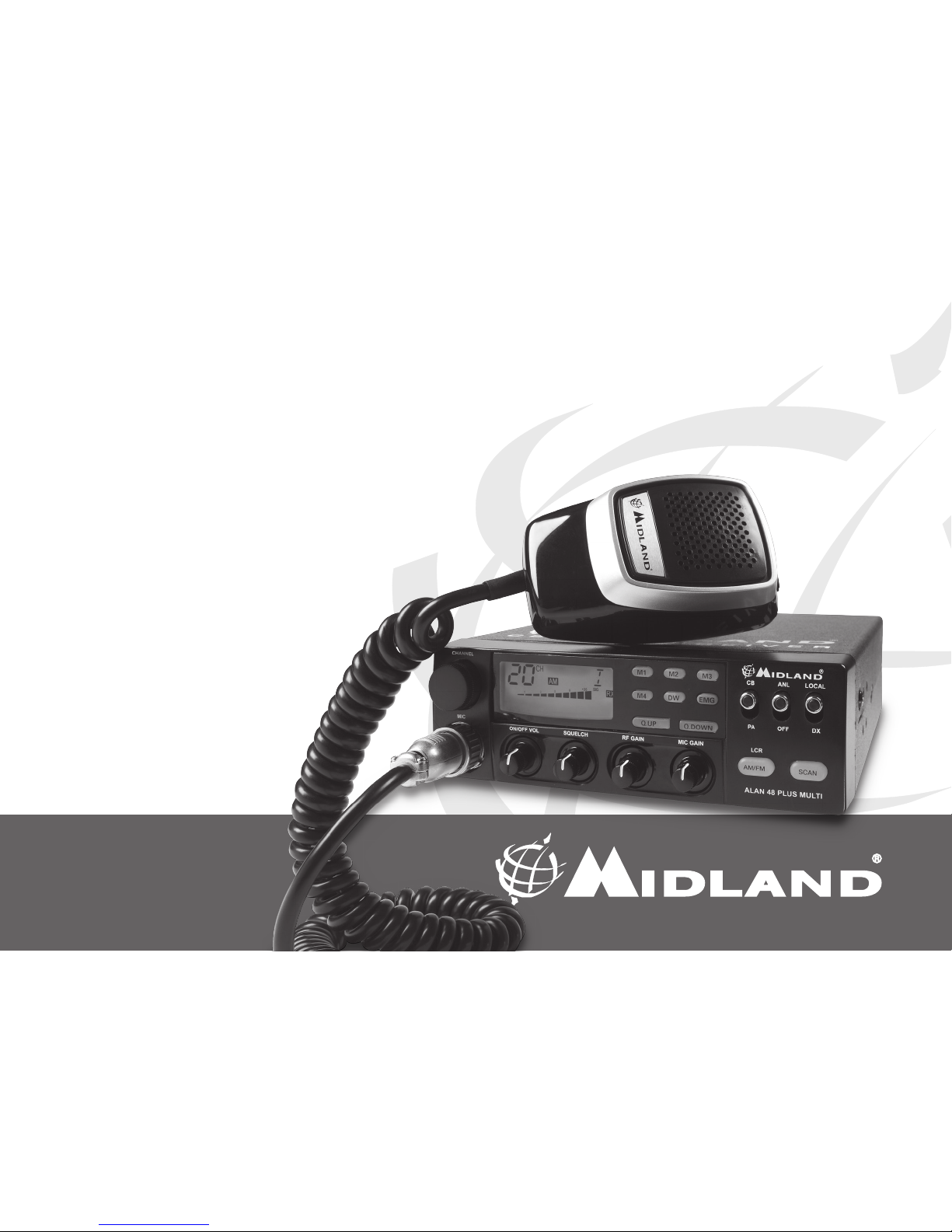
Your ALAN 48 PLUS MULTI B represents the state-of-the art in high-tech
engineering. Designed for the Citizen Band Mobile operation, this compact
package is big in performance. It is a quality piece of electronic equipment,
skillfully constructed with the finest components. The circuitry is all a solid-
state, mounted on rugged printed circuit boards. It is designed for many
years of reliable, trouble-free performance.The night-light buttons allow the
night use.Your ALAN 48 PLUS MULTI B has a built Channel Phase-Locked
Loop synthesizer circuit.
The PLL circuit achieves a new technique for generating all the required
frequencies with fewer crystals. The result is much tighter frequency control
and superior reliability.
Page 3
2
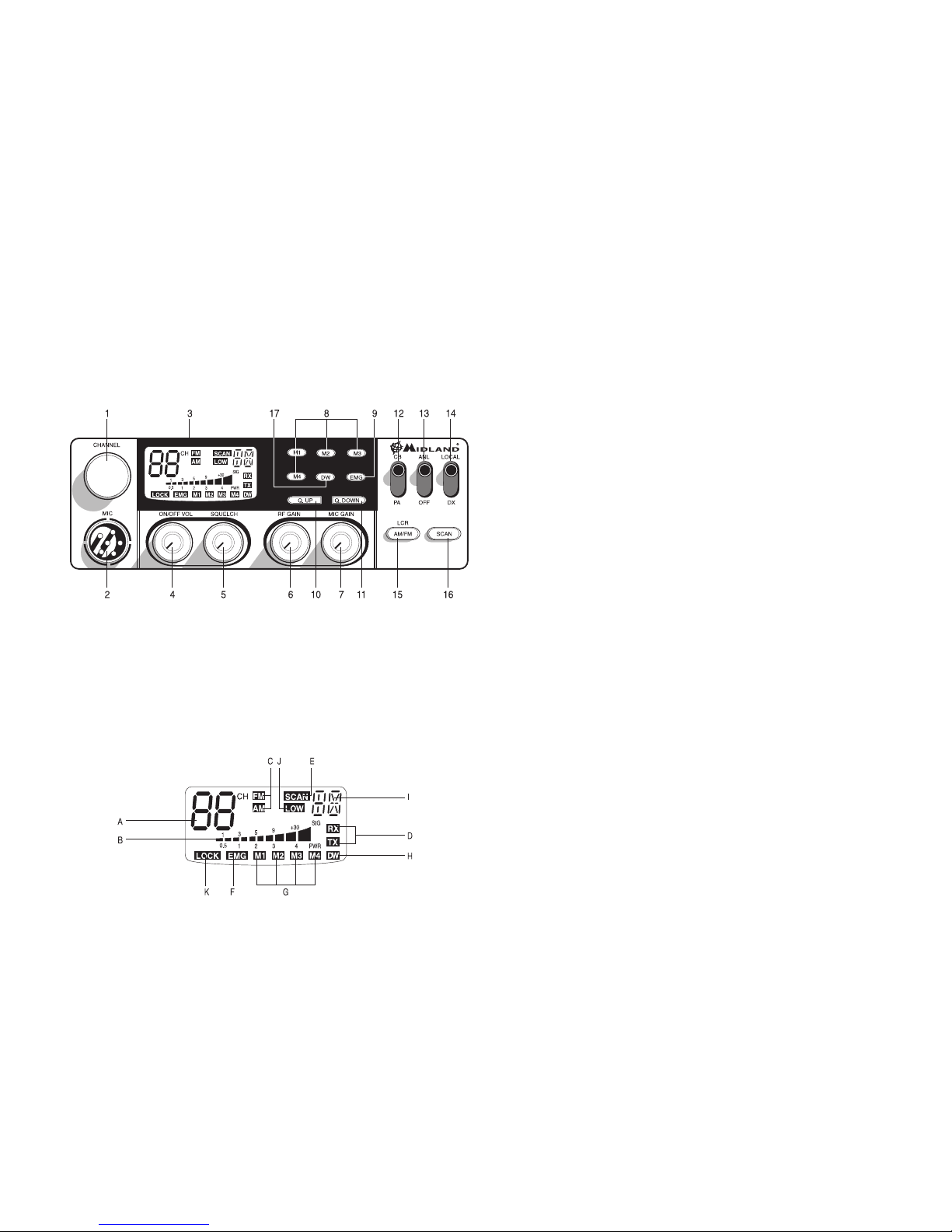
FUNCTION AND LOCATION OF THE CONTROLS
1. Channel selector
2. Microphone jack: Insert the mic connector into this jack.
3. Multifunction backlighted display.
A. Channel selected number
B. The received signal strength and the power of the transmitting
signal
C. AM/FM mode
D. RX/TX: TX=transmit mode; RX=receive mode
E. SCAN mode
F. EMG mode
G. M1-M2-M3-M4: preset memory channels
H. DW: Dual Watch activated
I. Frequency band selected.
J. LOW: displayed when the radio transmits in low power (this mode is
possible with some frequency bands only – see the frequency band
chart).
K. LOCK: microphone (UP/DOWN buttons) lock enabled.
4. “ON/OFF Volume” Control: in ‘’off’’ position your transceiver is OFF. Turn
this control clockwise to switch on the unit. Turn the knob clockwise a
little more to set the audio level, until you get a comfortable reception.
With ‘’PA-CB’’ selector set in ‘’PA’’ position, the knob controls the audio
output level.
5. “Squelch” Control: for the maximum receiver sensitivity, the control
must be regulated exactly where the receiver background noise disappears.
6. “RF” (Radio Frequency) Gain Control: it controls the reception sensitivi-
ty. To increase sensitivity, simply turn it clockwise. Sensitivity decreases
turning it counterclockwise. Low sensitivity is useful when very strong
signals are present in the band.
7. “Mic (Microphone) Gain Control”: in TX mode, it controls the micropho-
ne amplification. To get the best results, use the microphone and set the
optimum position for both the distance from your mouth and for the
amplification level, asking your partner when the modulation comes out
better.
8. “M1-M2-M3-M4” buttons: These buttons allow the storing and recalling
of 4 preselected channels. How to store: select the desired channel and
press M1 for at least 3 sec to store the choosen channel in the M1 memory. Repeat these steps to memorise the other presets.
9. EMG button: Emergency channel. By pressing it, the unit will be auto-
matically positioned on CH 9 (emergency channel). The display will show
“EMG”. It will not be possibile to accidentally change the channel.
ALAN 48 PLUS MULTI
Page 4

UK
3
10/11. “Q. UP-Q. DOWN” buttons: To skip 10 channels up (Q. UP) or 10 chan-
nels down (Q. DOWN).
12. ’’CB/PA’’ Selector. In the “CB” position, the unit operates as a transceiver.
You can use the PA (public address) function only if you connect a speaker to the PA jack. In this case the ‘’Volume’’ knob controls the amplification level.
13. ‘’ANL/OFF’’ Selector. In the ‘’ANL’’ position it activates an automatic noise
limiter for the impulsive noises (caused by the engine of the car or other
sources).
14. “Local/DX” Selector ”Local” position: to receive strong signal only.”DX”
position: to receive weak signals.
15. “AM/FM”(LCR) button: To select AM or FM mode. If you push it along
with the “SCAN” button at the switching on of the radio, it selects the
operating band, which will be displayed. If you select a frequency band
operating in FM mode only, this button enables the LCR function (Last
Channel Recall).
16. “SCAN” button: with this control, you can automatically seek for a busy
channel. Turn the Squelch clockwise until the background noise is no
longer heard.
Press the ‘’SCAN’’ button: the transceiver will scan automatically all the
channels until a carrier is being received. If you push it along with the
“AM/FM” button at the switching on of the radio, it selects the operating
band, which will be displayed.
17. DW button: This feature allows you to scan 2 channels of your choice.
When a signal on the second channel is picked up, the conversation on
the first is automatically interrupted and the receiver switches on the
second channel. The monitoring starts again 4 seconds after the carrier
disappears.
To activate this function, operate as follows:
a. Select the desired channel through the channel selector.
b. Press the “DW” button (DW blinks on the display).
c. Select the second channel.
d. Push the “DW” button again: the reading DW will remain fixed.
e. To disable this function, press the “DW” control.
REAR PANEL
18. Antenna connector (SO239 connector type).
19. S. Meter jack: it allows an external “S. Meter” connection.
20. “PA” jack: by connecting with an external loudspeaker, you can use the
unit as an audio-amplifier.
21. ”EXT” jack: external loudspeaker jack (the internal loudspeaker is exclu-
ded).
22. Power 12.6V DC: power supply cable.
Page 5

4
MICROPHONE
1. PTT: transmission button
2. UP/DOWN buttons: manual chan-
nel selector
3. LOCK button: it allows you to lock
the UP/DOWN buttons.
4. 6 pin microphone connector
INSTALLATION
Safety and convenience are the primary consideration for mounting any
piece of mobile equipment. All controls must readily available to the operator without interfering with the movements necessary for safe operation of
the veicle. Set the proper position in the car to install the transceiver using
the supplied supporting bracket or eventually the slide bracket. Tighten the
retaining screws. The fixing bracket must be close to metallic parts.
POWER SUPPLY
Be sure the transceiver is off. In the direct-voltage power supply, is very
important to observe the polarity even if the unit is protected against the
accidental inversion:
Red = positive pole (+)
Black = negative pole (-)
The same colors are present on the battery and in the fuse box of the car.
Correctly connect the cable terminal to the battery.
ATTENTION: To obtain best performances we recommend to install the radio in a place with enough air circulation.
INSTALLING AN ANTENNA
1. Place the antenna as high as possible.
2. The longer is the antenna, the better will be the performance.
3. If possible, mount the antenna in the center of whatever surface you
choose.
4. Keep antenna cable away from noise sources, such as the ignition switch,
gauges, etc.
5. Make sure you have a solid metal-to-metal ground connection.
6. Prevent cable damage during antenna installation.
WARNING: To avoid damage, never operate your CB radio without connecting a proper antenna. A periodical control of the cable and of the S.W.R. is
recommended.
REPLACING FUSE
If you replace the fuse for DC power Cord, use F 2A 250V type. The parameters and the symbol of the fuse are indicated in the following label.
F2A 250V +
Page 6

UK
5
HOW TO OPERATE WITH YOUR TRANSCEIVER
1. Screw the microphone plug into the microphone jack.
2. Make sure your antenna is securely connected to the antenna connector.
3. Make sure the SQUELCH control is turned fully counterclockwise.
4. Turn on the unit and adjust the volume control.
5. Select your desired channel.
6. To transmit, press the PTT button and speak in a normal tone of voice.
7. To receive, release the PTT button.
FREQUENCY BAND SELECTION
The frequency bands must be chosen according to the country where you
are going to operate.
Procedure:
1. Switch off the unit.
2. Turn it on while pushing the “AM/FM” e “SCAN” buttons at the same time.
3. Rotate the “CHANNEL” knob and select the desired frequency band (see
the chart here below).
4. To stop your selection, press the “AM/FM” button.
NOTE1: In the UK frequency band, you can select directly the EC band by
pushing the “AM/FM” button for 2 seconds.
NOTE2: If you select a frequency band which operates in FM mode only, the
“AM/FM” control enables the LCR function (Last Channel Recall).
FREQUENCY BAND CHART
Digits displayed Country
I Italy 40 CH AM/FM 4Watt
I2 Italy 34 CH AM/FM 4Watt
D Germany 80 CH FM 4Watt / 12 CH AM 1Watt
D2 Germany 40 CH FM 4Watt / 12 CH AM 1Watt
D3 Germany 80 CH FM 4Watt / 40 CH AM 1Watt
D4 Germany 80 CH FM 4Watt / 40 CH AM 4 Watt
EU Europe 40 CH FM 4Watt / 40 CH AM 1Watt
EC 40 CH FM 4Watt
E Spain 40 CH AM/FM 4Watt
F France 40 CH FM 4Watt / 40 CH AM 1Watt
PL Poland 40 CH AM/FM 4Watt
UK
England 40 CH FM 4 Watt English frequencies + EC
40 CH FM 4Watt
ATTENTION!
The frequency band definitely allowed all over Europe is 40CH FM 4W (EC)
Page 7

6
TECHNICAL SPECIFICATIONS
GENERAL
Channels ...................................................................... (see the frequency band chart)
Frequency Range* ....................................................................26.565 - 27.99125 MHz
Duty cycle (% on 1 hour) ......................................... TX 5% - RX 5% - Stand-by 90%
Frequency Control .......................................................................................................... PLL
Operating Temperature Range ................................................................... -10°/+55° C
DC input voltage ..................................................................................... 12.6V DC ±10%
Size ........................................................................................... 180 (L)x50 (H)x150 (P) mm
Weight ..................................................................................................................................1kg
RECEIVER
Receiving system ................................................. dual conversion superheterodyne
Intermediate frequency ........................................I° IF: 10.695 MHz • II° IF: 455 KHz
Sensitivity ..............................................................0.5µV for 20 dB SINAD in FM mode
..................................................................................0.5µV for 20 dB SINAD in AM mode
Audio output power @10% THD .........................................................2.0 W @ 8 Ohm
Audio distortion .............................................................................less than 8% @ 1 KHz
Image rejection ............................................................................................................. 65 dB
Adjacent channel rejection ......................................................................................65 dB
Signal/Noise ratio .........................................................................................................45 dB
Current drain at stand/by .......................................................................................250mA
TRANSMITTER
Output power ........................................................................................................... 4W max
Modulation .....................................................................................AM: from 85% to 95%
..............................................................................................................FM:1,8 KHz ± 0,2 KHz
Frequency response ..................................................................................... 300 Hz/3 KHz
Output impedance .................................................................. RF 50 Ohm unbalanced
Signal/Noise Ratio ...............................................................................................40 dB MIN
Current drain ............................................................................................................ 1100mA
* (covering all approved EU frequency bands)
Specifications are subject to change without notice.
A readily accessible disconnect device shall be incorporated in the installation wiring.
The disconnect device shall disconnect both poles simultaneously.
Hereby, CTE International declares that this device is in compliance with the essential
requirements and other relevant provisions of Directive 99/05/EC.
 Loading...