

Midland A-22075, A-22076 Maintance Manual
7733 Gross Point Road • Skokie, IL 60077 • (847) 677-0333 • Fax (847) 677-0138 • www.midlandmfg.com
Part Number: A-22075/6, Rev. 1.1
Issue Date: July 25, 2016
Supersedes: A-22075/6, Rev. 1.0
Internal-Style Pressure Relief Valve
A-22075 Series and A-22076 Series
Installation, Operation and Maintenance (IOM) Manual

P/N: A-22075/6, Rev. 1.1
Page 2 of 45
Table of Contents
1.0! Introduction .......................................................................................................................... 3!
1.1! Technical Specifications .................................................................................................. 3!
1.2! Valve Perspectives .......................................................................................................... 5!
1.3! Pre-Installation Regulations/Requirements ..................................................................... 8!
2.0! Valve Installation ............................................................................................................... 10!
2.1! Preliminary Considerations ............................................................................................ 10!
2.2! Procedure ...................................................................................................................... 10!
2.3! Leak Inspection ............................................................................................................. 12!
2.4! Valve Operation Notes and Precautions ....................................................................... 12!
3.0! Valve Disassembly ............................................................................................................ 13!
3.1! Procedure ...................................................................................................................... 13!
4.0! Valve Inspection ................................................................................................................ 19!
4.1! Inspection Procedure ..................................................................................................... 20!
5.0! Valve Assembly ................................................................................................................. 28!
6.0! Special Guidelines and Precautions on Pressure-Testing and Adjustment ...................... 29!
7.0! Valve-Pressure Testing Procedure .................................................................................... 30!
7.1! Initial Setup .................................................................................................................... 30!
7.2! Testing ........................................................................................................................... 32!
8.0! Valve-Adjustment Procedure ............................................................................................. 33!
8.1! Valve-Setting Adjustment .............................................................................................. 33!
8.2! Post-Test Procedure ...................................................................................................... 37!
9.0! Maintenance ...................................................................................................................... 39!
9.1! Prior to Maintenance Tasks Performed ......................................................................... 39!
9.2! Leak Repair on a Mounted Valve .................................................................................. 39!
10.0! Warranty .......................................................................................................................... 44!
P/N: A-22075/6, Rev. 1.1
Page 3 of 45
1.0 Introduction
The A-22075 Series and A-22076 Series Internal-Style Pressure Relief Valves are high-flow, corrosionresistant devices designed for use with crude-oil and ethanol tank cars requiring high-flow pressure relief.
• High-quality steel construction
• Triple seals on all potential leak paths to atmosphere
• Easy-to-replace seal design for ease of maintenance
1.1 Technical Specifications
Valve Model
Net Flow Area (in2)
Flow Rate (scfm)
Valve Pressure Setting
(psig)
A-22075/A-22076 Series
20
29,550
75
Table 1-1 Valve Specifications
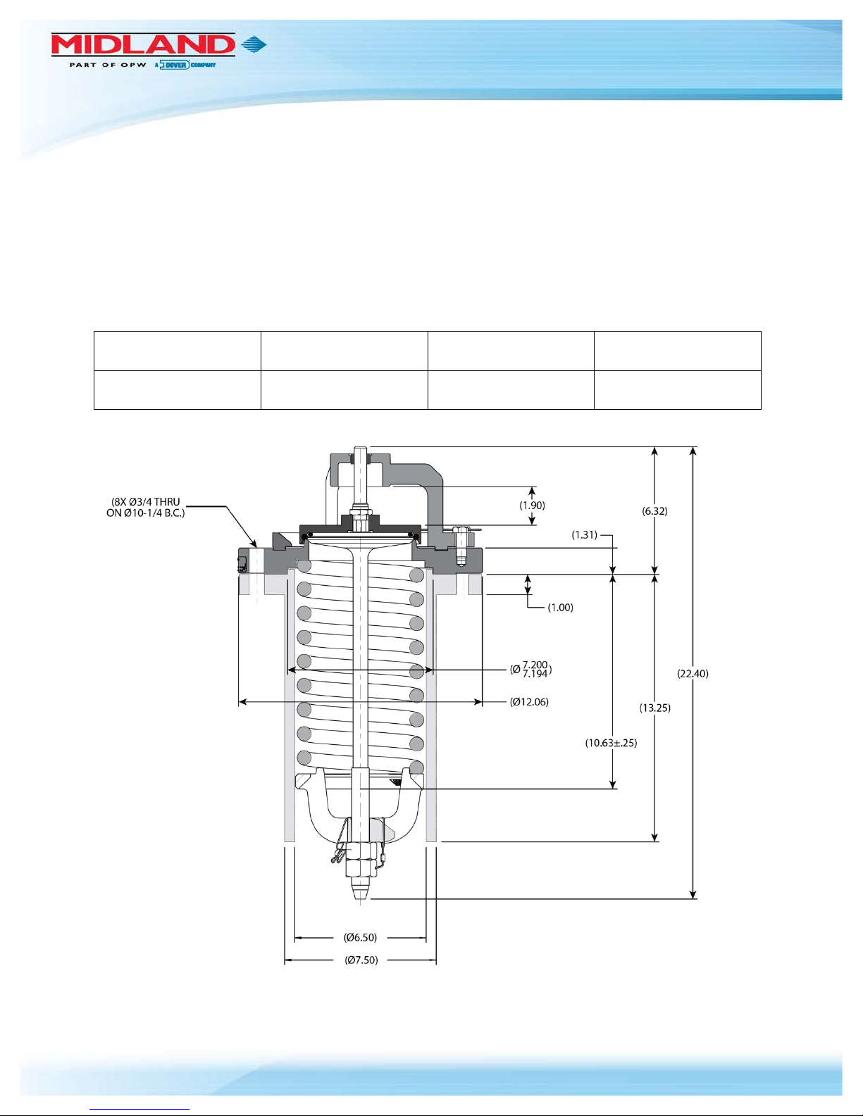
Figure 1-1 A-22075/A-22076 Valve Dimensions
P/N: A-22075/6, Rev. 1.1
Page 4 of 45
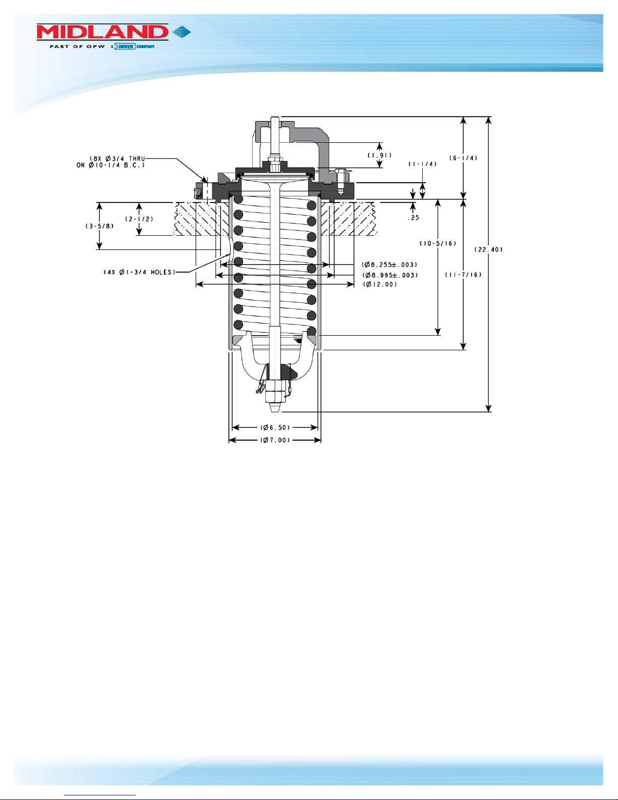
Figure 1-2 A-22075-PI and A-22076-PI Valve Dimensions
P/N: A-22075/6, Rev. 1.1
Page 5 of 45
1.2 Valve Perspectives
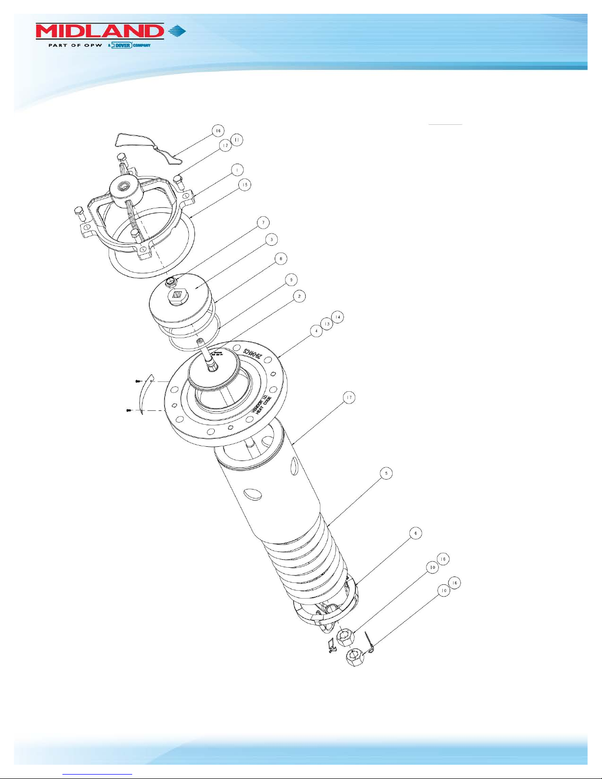
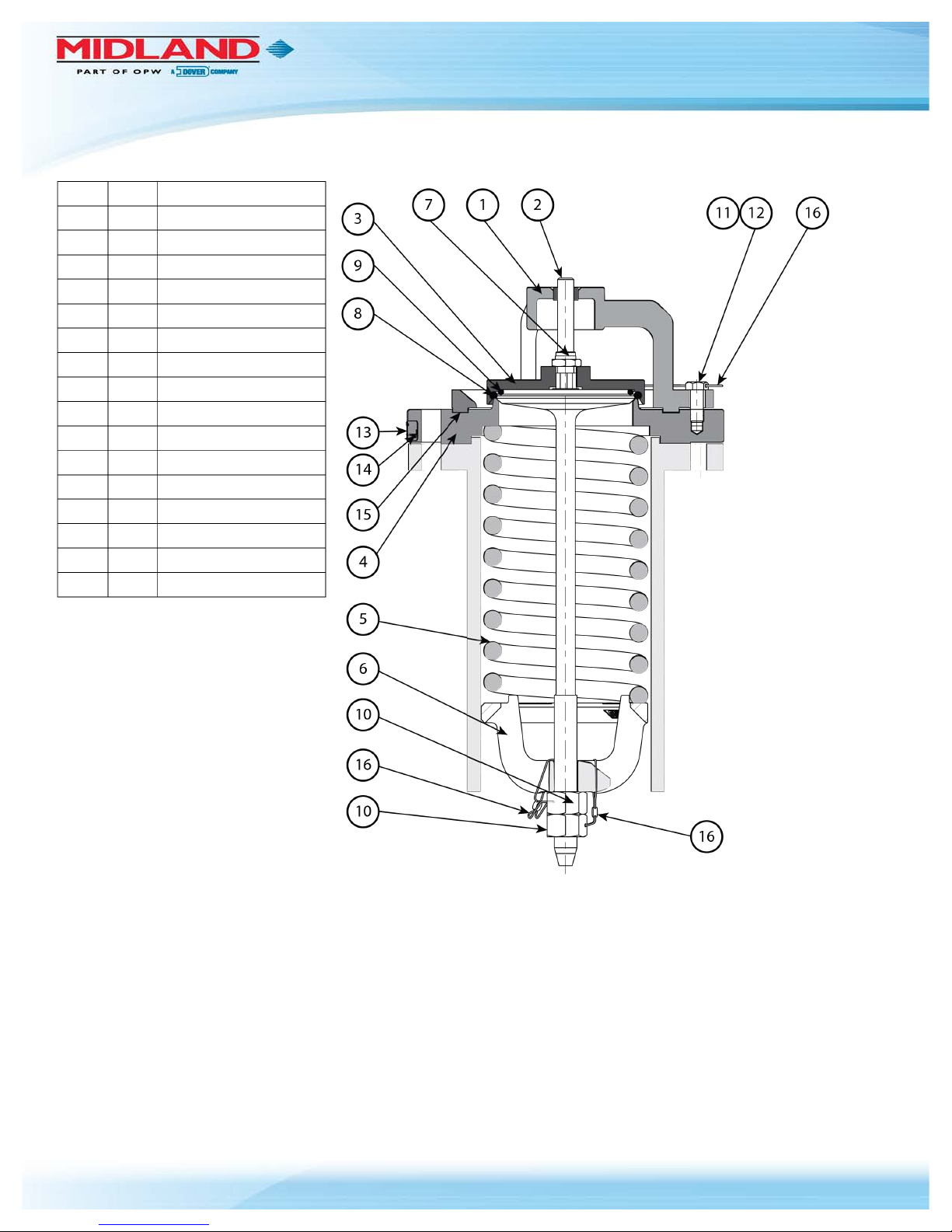
Figure 1-3 A-22075-PI/A-22076-PI Valve Exploded View
P/N: A-22075/6, Rev. 1.1
Page 6 of 45
Item
Qty.
Part Name
1 1 Top Guide with Insert
2 1 Valve Stem
3 1 Assembly Retainer
4 1 Valve Body
5 1 PRV Spring
6 1 Follower
7 1 Insert Locknut
8 1 O-ring (2-431)
9 1 O-ring (2-351)
10 2 Hex Nut
11 2 Hex-Head Cap Screw
12 2 Hex-Head Cap Screw
13 1 Name Plate
14 2 Drive Screw
15 1 Gasket
16 3 Wire-Seal Kit
Figure 1-4 A-22075/A-22076 Valve Components
P/N: A-22075/6, Rev. 1.1
Page 7 of 45
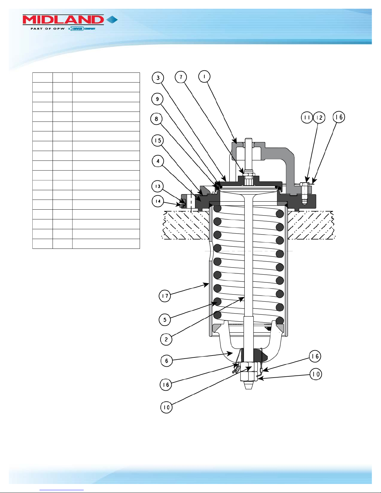
Item
Qty.
Part Name
1 1 Top Guide with Insert
2 1 Valve Stem
3 1 Assembly Retainer
4 1 Valve Body
5 1 PRV Spring
6 1 Follower
7 1 Insert Locknut
8 1 O-ring (2-431)
9 1 O-ring (2-351)
10 2 Hex Nut
11 2 Hex-Head Cap Screw
12 2 Hex-Head Cap Screw
13 1 Name Plate
14 2 Drive Screw
15 1 Gasket
16 3 Wire-Seal Kit
17 1 Tube Assembly
Figure 1-5 A-22057-PI/A-22076-PI Valve Components
P/N: A-22075/6, Rev. 1.1
Page 8 of 45
1.3 Pre-Installation Regulations/Requirements
1.3.1 Regulations
Midland internal-style valves are used in contact with a variety of products, many of which are hazardous
materials. The acceptance and transportation of products are regulated by the DOT and AAR in the
U.S.A., and in Canada by CTC and Transport Canada. Regulations of other governmental bodies must
be complied with for stationary and mobile applications. All personnel should be familiar with and follow
these regulations. Nothing in these instructions is intended to conflict with or supersede these regulations.
The information in this document was gathered from knowledgeable sources, but Midland Manufacturing
Corporation makes no representations or guarantees about its accuracy or completeness and assumes
no liability for this information.
Specifications are subject to change without notice.
1.3.2 Safety Precautions
Midland valves are used in connection with a variety of products, many of which are hazardous materials
and could cause serious injury or damage.
This valve should only be installed, operated and maintained by qualified personnel.
Read all of these instructions carefully before proceeding.
CAUTION: Toxic Hazard. Always use extreme caution and proper equipment when
involved with hazardous materials. To avoid exposure to toxic or hazardous
materials, make sure the tank car is empty and clean, and that the work area is free
of hazardous chemicals before removing or installing any valve.
WARNING: These internal-style pressure relief valves are spring-loaded assemblies
with a large amount of stored potential energy in the spring. Handle with care to
avoid damage to the valve stem, which could result in breakage and ejected piece
parts.
WARNING: When assembling or disassembling the valve, DO NOT position oneself
directly in front of the spring and stem. Instead, position oneself to the side away
from the valve. Unexpected component failure – valve stem or spring breakage may cause a sudden energy release discharging component parts a short distance
in an uncontrolled manner. Personal injury may be a result.
CAUTION
WARNING
WARNING
P/N: A-22075/6, Rev. 1.1
Page 9 of 45
1.3.3 Precautions for Mounted-Valve Repair
When performing maintenance on a pressure relief valve that is mounted on a railcar, observe the
following precautions:
• Wear protective clothing and equipment suitable for withstanding the materials to which you may
be exposed
• Position yourself on the upwind side of the valve when possible
• Work in a well-ventilated area
• Work with a partner who can help you in the event of an emergency
• Follow approved safety precautions for hazardous or toxic materials
• Obtain MSDS sheets for all the commodities used with the associated valve
1.3.4 Required Tools
Before arriving at the installation site obtain the required tools and supplies prior to performing the
procedures indicated in this guide.
Recommended Wrenches
SAE
Component
Torque (ft-lb)
Item #
3/4"
1/2-13 UNC Grade 8 Top-Guide Bolt
80
11 & 12
1-1/32"
3/4" Retainer Locking Nut
120
7
1-7/16"
7/8-9 UNJ Adjustment and Locking Nut
300
10
1-1/2"
Flats on Small Valve O-ring Retainer
Table 1-2 Required Tools with Torque Specifications
Other Tools and Supplies
Screwdrivers
Lint-free Cloth
2-Ton Two-Arm Puller
Emery Paper (400 grit, cut in 1" strips)
Silicone Grease (or equivalent lubrication)
Wire Brush
Torque Wrenches (0 – 300 ft-lb)
Table 1-3 Additional Recommended Tools and Supplies
P/N: A-22075/6, Rev. 1.1
Page 10 of 45
2.0 Valve Installation
2.1
Preliminary Considerations
2.1.1 New valves are tested, adjusted and sealed at Midland. If a new valve has been left in its original
packaging, is undamaged and is not more than six (6) months old, it may be installed on a tank
car without retesting or recalibration.
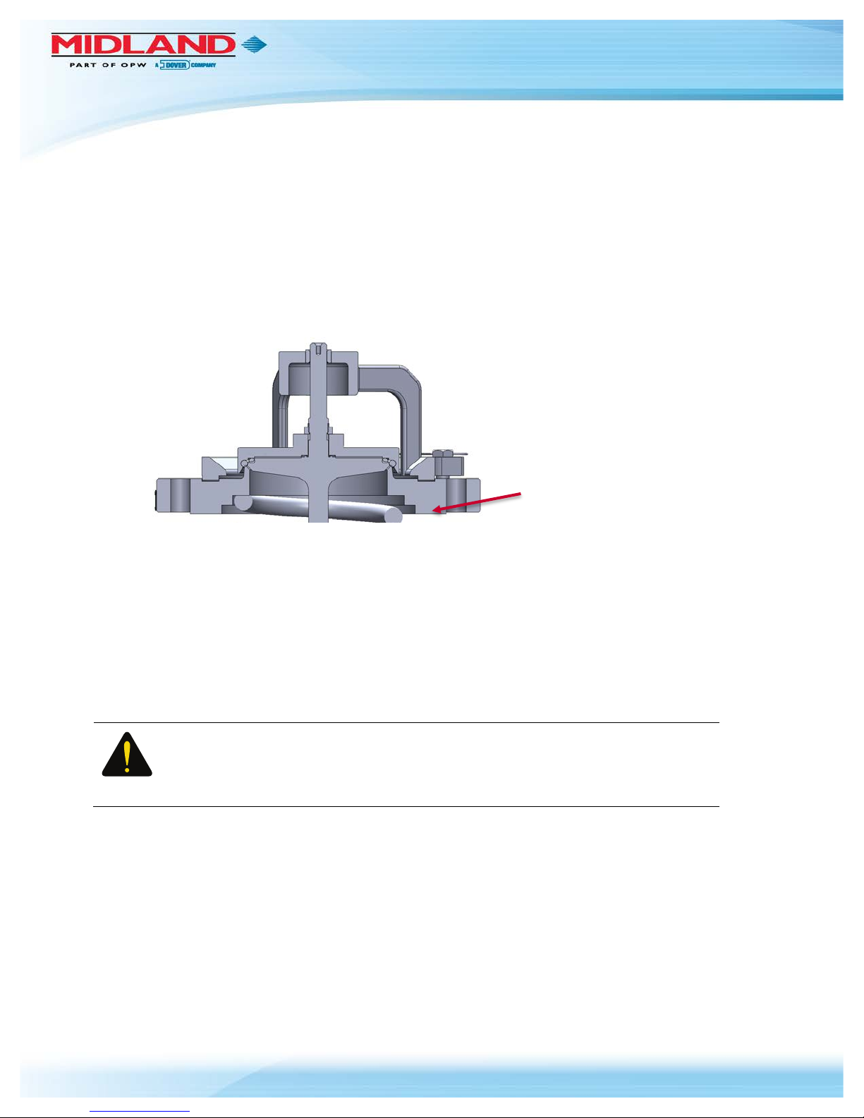
2.1.2 Prior to installation, ensure that the valve remains clean and the gasket-sealing surfaces are not
damaged.
Figure 2-1 Gasket-Sealing Surfaces
2.2 Procedure
2.2.1 Remove the old valve and then insert a soft rubber plug into the tank opening to prevent debris
from entering the tank during cleaning of the valve-mounting groove and studs on the manway
cover plate.
2.2.2 Using a wire brush, brush the threads of the mounting studs to remove rust or scale. Nuts should
move freely on clean studs. Studs should not exhibit excessive corrosion.
2.2.3 Remove and discard all used gasket material.
CAUTION: Groove Damage. In order to avoid groove damage, do not scratch the
metal in the bottom of the groove when removing the old gasket.
2.2.4 Using a lint-free cloth and appropriate cleaning solvent, wipe clean the valve and cover-plate
sealing surfaces and the mounting-stud threads.
2.2.5 For tongue-and-groove mountings, examine the sides of the groove. Because the valve tongue
fits tightly into the groove, any peening-over of the edges of the groove may make it difficult to
properly fit the valve tongue into the groove. If the sides of the groove are peened over, make
corrections to meet the AAR’s groove tolerances.
2.2.6 Install the new gasket. Ensure it is fully seated. When a groove gasket is fully seated, 1/16" of
free space should remain above the gasket to permit locating and entry of the valve tongue.
CAUTION
Gasket-Sealing
Surfaces
P/N: A-22075/6, Rev. 1.1
Page 11 of 45
CAUTION: Do not use a sharp tool to press the new gasket into place or gasket
damage may result.
2.2.7 For tongue-and-groove mountings, inspect the tongue of a reconditioned or retested valve by
running your fingernail around its inner and outer edges to check for damage. The tongue
dimensions have diameter tolerances of ±0.003", thus any excess material on these diameters
will make it difficult to fit the tongue into the groove. If the tongue is peened over, remove excess
material to meet AAR tongue tolerances.
CAUTION: To prevent tongue damage, do not install a valve having damaged
sealing surfaces.
2.2.8 Remove the rubber plug (which was inserted in Step 2.2.1) from the cover plate.
2.2.9 Position the valve gently into the mounting. Align the body holes over the studs and lower the
valve while positioning the valve tongue in the cover-plate groove.
CAUTION: Tongue Not in Cover-Plate Groove. Verify that the valve tongue has fit
into the cover-plate groove. It must be so engaged before continuing with the next
step or valve damage may result.
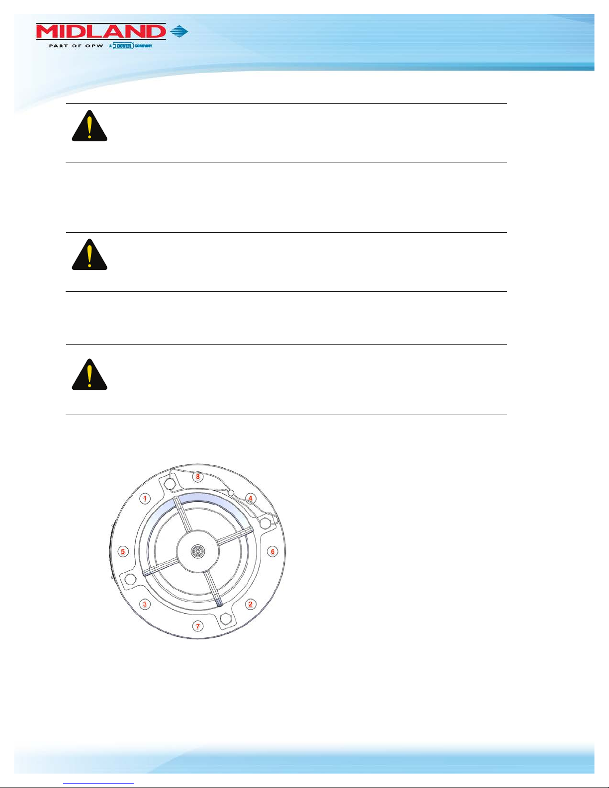
2.2.10 Install the nuts and tighten them in 1/3-torque increments in a diagonally alternating sequence to
a torque specified by the gasket specified, as shown in in Figure 2-2 below. Consult gasket
manufacturer for recommended torque requirements.
Figure 2-2 Tighten in Alternating Sequence
CAUTION
CAUTION
CAUTION
P/N: A-22075/6, Rev. 1.1
Page 12 of 45
CAUTION: Uneven Gasket Compression. Do not over-tighten the nuts on one
side of the valve as this may tilt the valve and result in uneven gasket compression.
2.3 Leak Inspection
2.3.1 Test all newly installed valves under pressure to confirm that no leaks are present.
WARNING: Valve Leakage. Improper valve-tongue seating in the flange groove,
loose nuts and damaged gaskets may result in leaks at the valve-mounting joint.
2.4 Valve Operation Notes and Precautions
NOTICE: Operation of the valve must conform with all applicable TC, AAR, DOT
specifications (Parts 173.31, 174.67, etc.), other governmental bodies, and the
operating instructions of your company.
The pressure relief valves are spring-loaded and are actuated by overpressure in
the railcar tank. There are no provisions for manual activation of the valve.
CAUTION: Incorrect Setting. Never adjust the spring compression of a valve while
it is mounted on the vessel cover plate or incorrect settings may result.
CAUTION
WARNING
NOTICE
CAUTION
P/N: A-22075/6, Rev. 1.1
Page 13 of 45
3.0 Valve Disassembly
NOTICE: Valve disassembly should only be done by trained personnel with access
to the proper machines, tools, procedures and personal-protective equipment
(PPE).
3.1 Procedure
CAUTION: Spring-loaded Assembly. During valve-spring disassembly, the valve
contains springs under load. DO NOT attempt to disassemble the valve without first
reading these instructions or injury may result. Spring pressure must be adjusted to
minimum and a bench clamp or press used for disassembly.
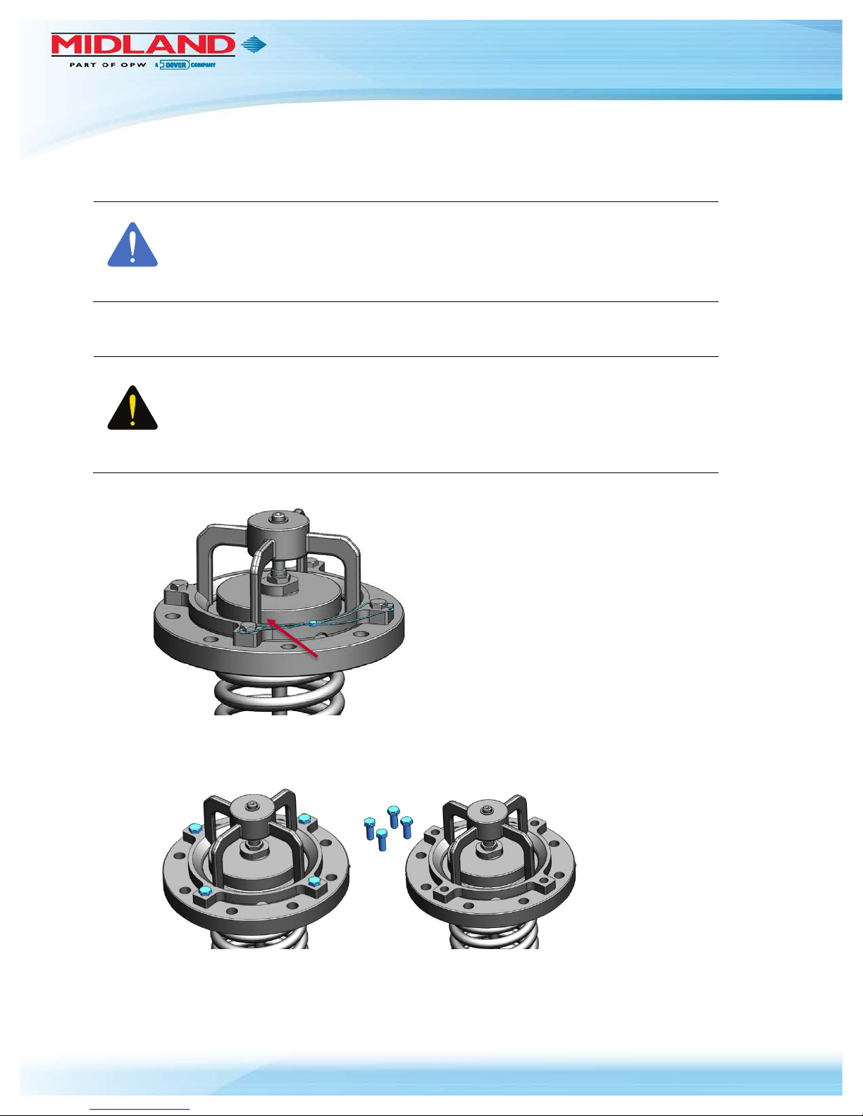
3.1.1 Remove the seal wires (item 16) from top-guide bolts (items 11 and 12).
Figure 3-1 Remove Wire
3.1.2 Remove the four (4) bolts (items 11 and 12) securing the top guide (item 1) to the valve body
(item 4).
Figure 3-2 Remove Four (4) Bolts
3.1.3 Remove the top guide (item 1) from the body (item 4). You may have to tap it loose with a brass
hammer.
NOTICE
CAUTION
P/N: A-22075/6, Rev. 1.1
Page 14 of 45
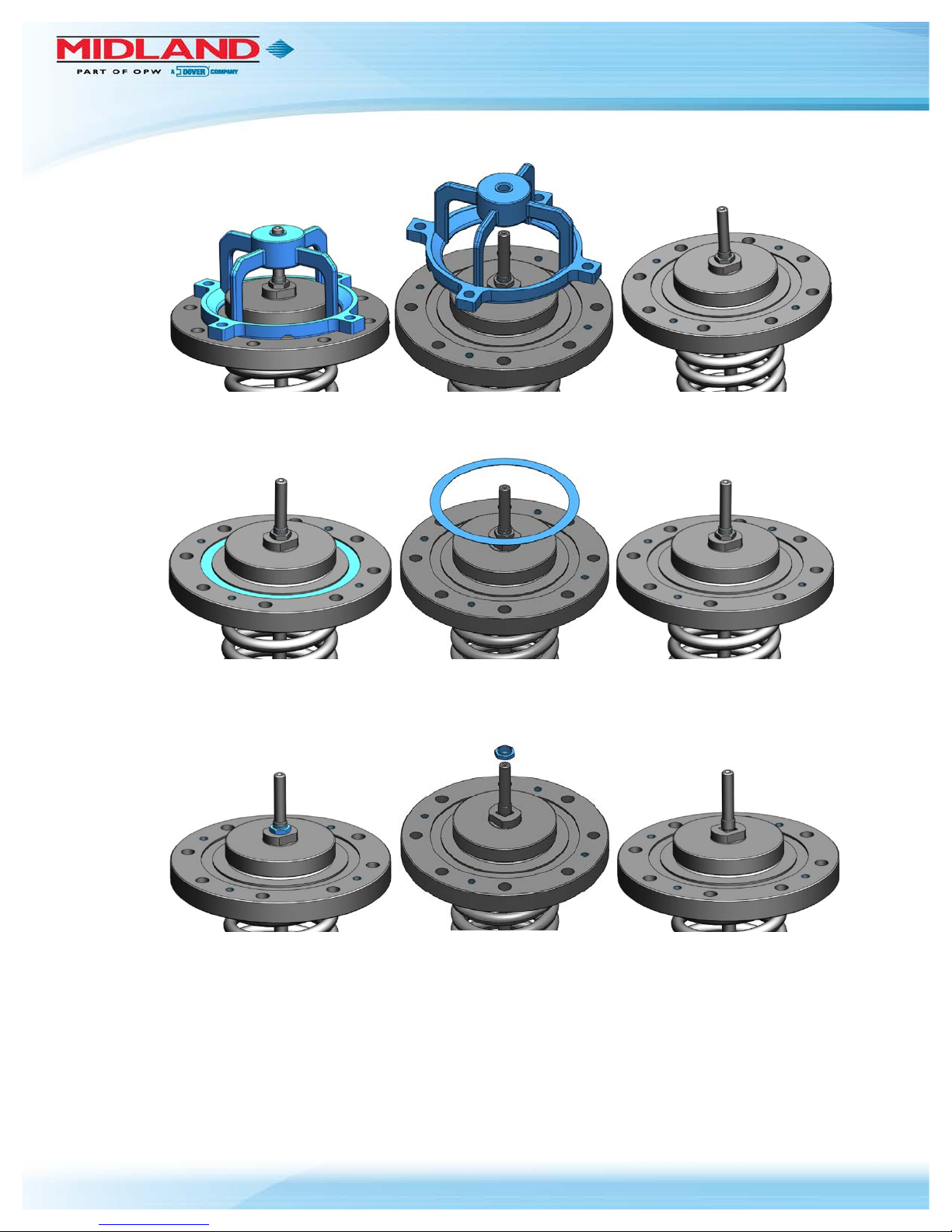
Figure 3-3 Remove Top Guide from Body
3.1.4 Remove the sealing gasket (item 15) and dispose.
Figure 3-4 Remove Sealing Gasket
3.1.5 Loosen the locknut (item 7) on the stem (item 2) while holding the retainer in place. See Table 1-2
for recommended wrench size. Remove the locknut from the valve stem.
Figure 3-5 Remove Locknut from Valve Stem
 Loading...