

Page 1

USER MANUAL
for
MBBS – MIDI controller
firmware version 2.0
www.midi-hardware.com
Roman Sowa 2011
Page 2

Table of contents
1 Overview..............................................................................................4
2 Connections & Power Supply..................................................................4
3 Keyboards.............................................................................................5
3.1 Split for special function inputs - #905......................................................6
3.2 Keyboard contacts debouncing - #99........................................................7
4 Potentiometers & Control Voltages..........................................................7
4.1 Analog inputs update rate - #98..............................................................8
4.2 Bitwise resolution of analog inputs - #96..................................................8
5 MIDI settings and special functions........................................................9
5.1 Transposition (starting note)...................................................................10
5.1.1 Middle "C" select - #1................................................................................10
5.1.2 Transpose +/- buttons................................................................................10
5.1.3 Transpose +/- command - #10, #11...........................................................10
5.1.4 Global Transpose........................................................................................11
5.2 MIDI event assignment for keyboards and analog inputs..........................11
5.2.1 Control Change - #2 CC.............................................................................11
5.2.2 Pitch Bend - #2128....................................................................................11
5.2.3 Program Change - #2129...........................................................................12
5.2.4 Channel After Touch - #2130......................................................................12
5.2.5 Standard keyboard action – single notes - #2131.........................................12
5.2.6 Note on only - #2132.................................................................................12
5.2.7 Note off only - #2133.................................................................................12
5.2.8 One-touch Patch Recall - #2134..................................................................12
5.2.9 CC keyboard - #2135.................................................................................13
5.2.10 MIDI channel shift for all controls - #2136.................................................13
5.2.11 Small Transposer - #2137.........................................................................13
5.2.12 Big Transposer - #2138............................................................................13
5.2.13 Velocity - #2139.......................................................................................13
5.2.14 Native Instruments B4 chorus/vibrato - #2140...........................................14
5.2.15 MidiTzer stops control - #2141..................................................................14
5.2.16 Ahlborn Archive module stops control - #2142...........................................14
5.2.17 Ahlborn Organs stops control - #2143.......................................................14
5.2.18 Program selector - #2144.........................................................................14
5.2.19 Bank selector - #2145..............................................................................15
5.2.20 Ahlborn Common Functions - #2146.........................................................15
5.2.21 3-note chord collect - #2147.....................................................................15
5.2.22 Dual note (layered sound) - #2148...........................................................15
5.2.23 One time velocity setup - #2149...............................................................15
5.2.24 Single keyboard transposition buttons - #2150 to #2153............................16
5.2.25 Channel set buttons - #2154 & #2155......................................................16
5.2.26 All keyboards transposition - #2156 to #2159............................................16
5.2.27 MIDI notes for stops control - #2160........................................................16
5.2.28 Reversed notes action- #2161..................................................................16
5.3 MIDI Channel - #3.................................................................................17
5.4 Program Change - #4.............................................................................17
2
Page 3

5.5 Keyboard split - #5.................................................................................17
5.6 Programming Patch Recall Buttons - #6...................................................18
6 MIDI utilities.......................................................................................19
6.1 MIDI monitor - #971..............................................................................19
6.2 Factory defaults - #979..........................................................................19
7 Scanners.............................................................................................20
7.1 PDS - diode matrix pedal scanner............................................................20
7.2 DMS-2K dual keyboard matrix scanner.....................................................20
7.3 BBSP - common ground pedals scanner...................................................21
7.4 BBS-1K common ground keyboard scanner..............................................22
7.5 BBS24 little scanner for contacts & pots...................................................22
7.6 LITSW - button scanner with LED drivers.................................................23
7.6.1 Split point - #905.......................................................................................24
7.6.2 Independent mode - #908..........................................................................24
7.6.3 Dependent mode - #909............................................................................24
7.6.4 Bank/preset select - #910...........................................................................25
7.6.5 Disable bank/select mode - #911................................................................25
7.6.6 Contact on/off (keyboard scanner) mode - #912..........................................25
7.6.7 CC value (pot scanner) mode - #913...........................................................25
7.6.8 Left split blink - #916.................................................................................25
7.6.9 Right split blink - #917...............................................................................25
7.6.10 All LEDs blink - #918................................................................................25
7.6.11 Reset to defaults - #929...........................................................................26
7.7 POT12 - potentiometer scanner...............................................................26
7.8 MiDisp - 2x16 characters display..............................................................27
7.8.1 Toggle mode - #908...................................................................................27
7.8.2 Momentary mode - #909............................................................................27
7.8.3 Device ID set - #911..................................................................................27
7.8.4 Device ID show - #920...............................................................................28
7.8.5 Display blink - #918...................................................................................28
7.9 KEYPAD - numeric entry for user MIDI settings........................................28
MIDI controller boards described here are products of:
"MIDI-hardware" Roman Sowa
ul. Azotowa 15B
41-503 Chorzów
Poland
phone +48 32 7633 931
email [email protected]
www.midi-hardware.com
www.midimplant.com
© 2011, Roman Sowa
boards made and manual printed in Poland, EU
manual edition 9
3
Page 4
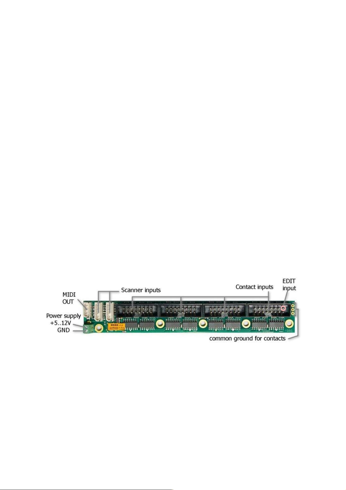
1 Overview
This manual describes the use and functionality of MBBS, a small MIDI controller
for one 5-octave keyboard, as well as all compatible scanners. The board described
here is intended for small 1-keyboard controllers, and smaller organ consoles. Apart
from direct inputs for 5-octave keyboard with common bus bar, there are 2 scanner
inputs. Each of them can take up to 128 keys if keyboard scanner is connected, or
up to 64 potentiometers if pot scanner is used. This way up to 5 keyboard scanners
can work together but only one input at a time can work with a chain of
potentiometer scanners. It is possible to combine keyboard and potentiometer
scanners on one input, thus 319 keys and 64 pots.
Features:
• 63 direct inputs for keyboard switches
• 2 scanner inputs, for keyboards and potentiometers
• user defined split for every keyboard
• independent transposition for all keyboards/splits
• user defined MIDI channel for each keyboard/split and pot
• user defined MIDI event for each pot and keyboard split
• up to 15 special function, user defined inputs (transpose, channel, etc.)
• select Program Change from keyboard by entering number 001-999.
• all settings remain after disconnecting power
• DC power supply (5V-12V DC)
2 Connections & Power Supply
Recommended power supply range is between 5 and 12V DC. It is possible to run
this board from lower voltage, but its operation is not guaranteed then. Current
consumption depends on the number of attached scanners and varies between 1 to
5mA, making it suitable for battery operation. This figure doesn't include the load
caused by potentiometers if they are used with appropriate scanners. If LCD
module takes more current, about 15mA per display. The board comes with screw
terminals for power. Make sure to use proper polarity of power supply. Connecting
power in reverse will not cause any damage, but of course it will only work with
proper power polarity.
4
Page 5
The last (64th) contact pin marked in the picture as "EDIT" should be connected to
momentary switch. This allows changing al user settings as described in chapter 5.
You don't need that if special programing KEYPAD is present in the MIDI system or
if you don't want to change any default settings.
Typical DIN5 MIDI output is available with supplied special cable connected to 3way connector as indicated.
3 Keyboards
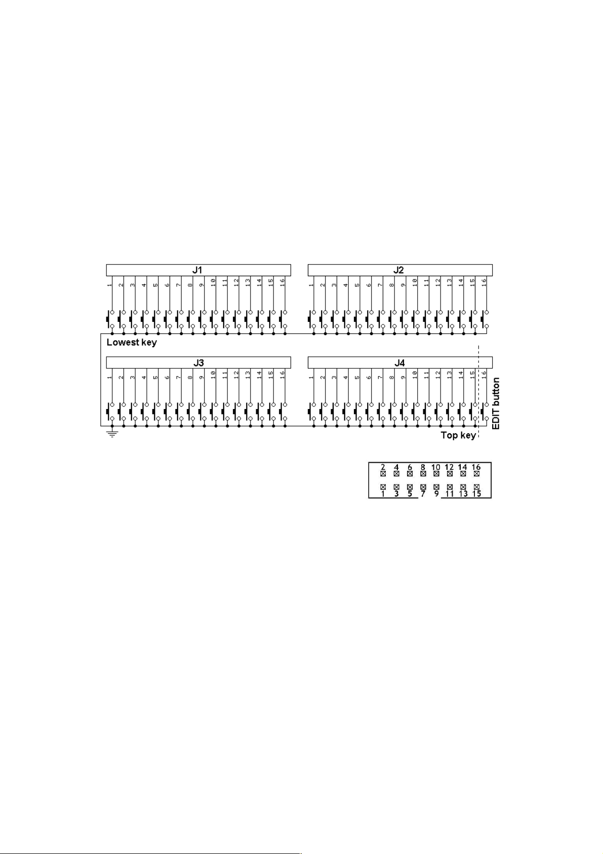
Main keyboard connects to 4 on-board IDC headers according to the schematic
below.
Each black connector holds 16 inputs for keyboard
switches. The pin numbering within one connector
is shown here. Notice orientation of the keying slot:
At the edge of the board there are 3 soldering pads (holes) to connect common
ground of all switches in a keyboard. The common may be connected there, or at
the minus (GND) supply lead of MBBS, whatever is more convenient.
Additional keyboard switches may be connected to keyboard scanners. There are
several scanners available: for 32, 64, 128 keys, with switches organized in 8x8
matrix and single-rod bus-bar. All are described in chapter 7. Type of the scanner is
determined by keyboard size and the way how switches are organized. Connection
between keyboard scanner and MBBS main board is always the same, regardless of
the type of scanner. MIDI settings of those keyboards can be changed by the user
after all connections are in place.
Most commonly found in modern keyboards is 8x8 diode matrix. 8x8 scanner driver
can be used in such keyboards. The matrix is very simple circuit, made of diodes
forming electric XY array of 8 rows and 8 columns. It is integral part of the contacts
board found beneath the keys. Those kind of keyboards can work directly with
DMS-2K scanner. Its advantage is that you can connect 2 keyboards to one board.
5
Page 6

Older keyboards, and especially those used in old analog organs, usually don't have
such a thing, so in order to use 8x8 scanner, you must build diode matrix yourself,
assuming it is possible to separate the contacts into groups of 8 keys. In other
cases, when making diode matrix is impractical, you may use bus-bar type of
scanners (BBS), where all keys share only one common bus. This is typical
keyboard arrangement in all old organ consoles. Below is a short table showing
which scanner type can be used with different keyboards:
Keyboard type DMS BBS PDS
Independent switches, no connections
Switches organized in 8x8 diode matrix
Switches organized in 6x12 and other
One common rail for all switches
● - can be used directly
◊ - with additional diodes
‡ - requires rewiring of existing contacts.
◊ ● ◊
● ‡ ●
‡
‡◊ ● ‡◊
3.1 Split for special function inputs - #905
By default all 63 on-board inputs are treated as keyboard interface, playing notes,
or other similar MIDI events as described in chapter 5. But you can designate a few
inputs for other tasks if less keyboard inputs are required. Such altered inputs work
like they would be potentiometer inputs, but only with min and max values (0 and
127) possible. If those buttons are assigned this way, each of them can be
individually set to different event type and MIDI channel. It creates some new
possibilities - for example you can assign transpose/octave +/- buttons, channel
+/- buttons, and a few non-continuous CCs, with most obvious examples like
Sustain or Portamento.
There can be up to 15 such inputs, and they are always placed at the top of note
contacts, in the last, 4th connector (J4) of MBBS. This special mode is available
only in MBBS and not in any of connected scanners.
To define the split point between normal note inputs, and special CC inputs, play
any note at MBBS on-board inputs, enter command #905 from the keypad (or use
on-board inputs in sequence: 64, 10, 1, 6), and then press the top key of desired
note part. All inputs above this point, up to the EDIT input, will be now acting like
inputs of POT scanner and can be individually programmed. To cancel this setting,
and turn the whole range as normal inputs, repeat the procedure, but now set the
split point at the last note input (63). Do NOT connect any potentiometer, or
variable voltage to those inputs. They are only capable of working with switches, or
logic levels. Applying other voltages may damage the board.
This kind of split has nothing to do with keyboard split described in chapter 5.5 and
can be used independently of that one.
6
Page 7

3.2 Keyboard contacts debouncing - #99
Every kind of contact bounces sometimes. This is very short series of contact
closures and openings, making instable signals for detecting key on and key off. To
prevent the controller from sending MIDI notes on every bounce, a special
technique is performed, called debouncing. All boards from midi-hardware.com
perform contact debouncing, but MBBS also provides possibility to adjust the
strength of this process. By default debouncing is set to 20ms, but you can change
it to one of 10 steps from 2ms to over 40ms. If there are no bouncing effects
apparent in your keyboard, there's no need for long debouncing, and it can be
shortened to reduce latency. But wwith old rusty wire contacts, it may be necessary
to set the debouncing to a higher level. This increases latency, but prevents from
burst of unwanted notes with every key going up or down. To change debouncing
time, you must play any note on the keyboard connected to internal inputs of MBBS
(not on the scanners) and use command #99x, where 3rd digit (x) determines
debouncing strength. 0 means almost no debouncing and minimum latency, while 9
is maximum debouncing and biggest latency. See chapter 5 for general guidelines
on how to enter commands. If you have dedicated LCD module setting is easier to follow because short prompts are displayed after each digit.
MiDisp
, this
4 Potentiometers & Control Voltages
Pot inputs are available with use of proper expanders, like POT12, BBS24, PDS or
BBSP. They can be used as continuous controllers for things like volume,
modulation etc. Usually those inputs would be connected to potentiometers, but it's
possible to use them as analog inputs with range of 0..+5V. Applying voltage of 0V
causes generation of CC with lowest value, while +5V makes highest possible value
of assigned MIDI parameter. Each input in the system has separately assigned MIDI
event and channel. This assignment can be easily changed by the user with use of
special programing keypad, or lowest 10 keys of any connected keyboard. Every
potentiometer scanner is described in chapter 7, with connection schematics.
All potentiometers must be linear taper (not audio) in range 10-50k,
preferably 20k.
If there are 2 or more potentiometer scanners in the system, they must be chained,
i.e. first board is connected to MBBS, and second one is connected to first POT
board, etc. If you use 2 inputs of MBBS to connect POT boards, they both will share
the same settings. That means it would be like having 2 potentiometers for the
same MIDI parameter on the same channel. The chain of potentiometer scanners
can be connected to any one of the MBBS inputs, or any daisy-chain input of other
connected scanners, but only one. Only keyboard scanners can be connected to all
inputs at the same time. You can mix different kinds of POT scanners in one chain.
There can be for example two POT12, and BBSP at the end. The total number of
potentiometer inputs should not exceed 64. All additional inputs will be ignored.
Every POT scanner has pins for connecting outer leads of the pots. They are
7
Page 8
described as +5V and GND. You must not connect any power to those pins, they
are only for connection end potentiometer taps.
All cables leading from POT scanners to potentiometers should be either shielded or
very short (no more than 30cm). Using long non-shielded cable may generate
spurious MIDI messages when unexpected. Typical microphone cable is good
enough for preventing this, even the low-cost one.
4.1 Analog inputs update rate - #98
All analog inputs of potentiometer scanners (POT12, BBS24, PDS, BBPS) translate
input voltages, or potentiometer position into MIDI. Actual pot position is updated
via MIDI every time it changes. This update is however not immediate - this is
common to any MIDI knob box. The fastest response for potentiometer movement
on a single input is about 5ms. It means that when you constantly move the pot,
MBBS will update the MIDI parameter every 5ms. This is more than enough for
most of uses. In some instruments, either hardware, or virtual, some problem may
occur when there is heavy MIDI load. It is also sometimes desirable to limit MIDI
traffic e.g. to minimize the size of MIDI file recorded in a sequencer. It is possible to
change this setting using command "#98n" from the keypad, where "n" determines
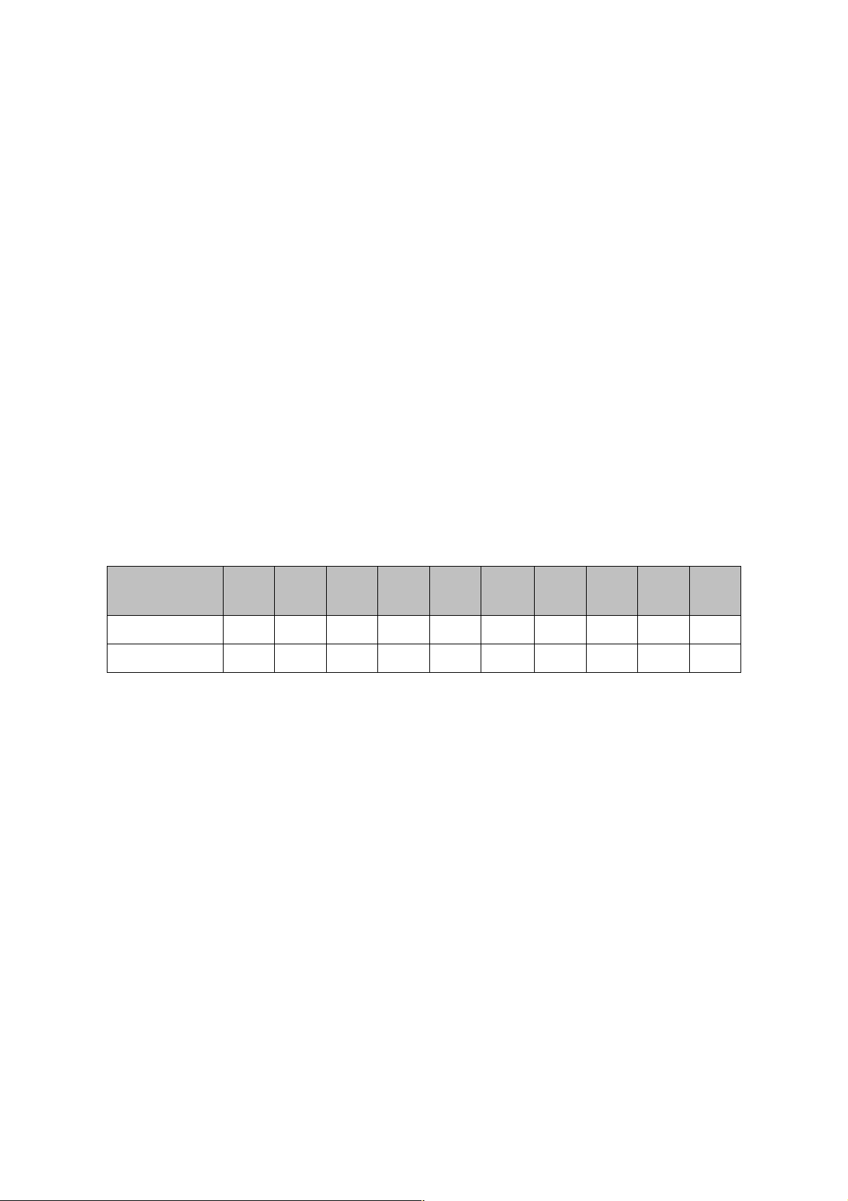
update rate according to the table below. More on how to enter digits and setting
procedures, in chapter 5. Default factory setting is 18ms.
keypad
sequence
pot latency 5ms 7ms 9ms 13ms
update rate
This setting is available for all pot-capable boards (POT12, BBS24, BBSP, PDS)
connected to MBBS board. Each board can have different update rates, but all
inputs in one POT board work with one rate. For example you can set it to 50ms on
first POT scanner, and 13ms on second one (assuming you have 2). As usual, to
change any settings for particular board, select it first by moving a bit any
potentiometer connected to board in question. Then using your keypad enter the
code from above table. New settings will be activated and remembered.
#980 #981 #982 #983
200Hz 145Hz 115Hz 80Hz 55Hz 40Hz 30Hz 20Hz 15Hz 10Hz
#984
18ms
#985 #986 #987 #988 #989
25ms 35ms 50ms 70ms 0.1s
4.2 Bitwise resolution of analog inputs - #96
Usually all MIDI parameters have 128 possible levels, determined by 7 bit nature of
MIDI standard. In some cases it may be useful to reduce the number of possible
levels, or in another words - number of information bits. For example if you want to
use MIDI channel rotary selector, described in chapter 5.2.10, it's better to reduce
resolution to 4 bits, and have only 16 levels in full pot rotation. In some software
synthesizers you can select parameters using only a fraction of the full CC range.
And in organ emulators it's also sometimes desirable to have only a few steps in full
8
Page 9

pedal travel if it's used e.g. for crescendo.
Bit resolution is user adjustable in a similar way as update rate described above, by
using command #96x, where "x" is desired bit resolution. For example #967 makes
the pot input 7-bits wide (128 levels), this is default mode of operation. For
example #963 sets it to 3-bit resolution, allowing for only 8 levels (and 8 possible
MIDI messages sent) per full pot rotation.
It's adjustable per single input, so you can set every analog input in the system
individually To change resolution of the input, turn the potentiometer connected to
that input, and then enter #96 from the keypad, followed by number of bits you
want to set. If this potentiometer was previously set to very low resolution, like 1 or
2 bits, you have to turn the pot almost full rotation to select it for EDIT operations.
To start any pot for any kind of configuration (event, channel, resolution) it must
first make some action, and when you have only so little levels, it takes much more
rotation to cross next valid level and indicate to MBBS board "hi, I'm the last used
pot, any setting changes apply to me now!"
Bit resolution is available only with the following boards: POT12 v1.2 and higher,
PDS, BBS24 and BBSP v1.0 and higher.
5 MIDI settings and special functions
All settings are accessible from any keyboard connected to MBBS. Last contact pin
of MBBS should be connected to momentary switch. This is the entry to EDIT mode
and allows changing all settings of entire set. Detailed procedures for all settings
are described later in this chapter. To make the settings more ergonomic and easier,
there's optional numeric keypad available, similar to phone keypad. It is connected
the same way as any keyboard scanner with 4-wire cable, and works like actual
keyboard, meaning it is possible to play notes with it. But the advantage is the „#”
key, which duplicates the EDIT button.
To change any settings in EDIT mode, you must enter new value of given
parameter. To do so, use lowest 10 keys of the keyboard as numeric entry. Lowest
key is digit „0”, while 10th key is digit „9”. This becomes obvious with mentioned
numeric keypad. As a general rule, any change to a controller (keyboard, or
potentiometer) requires selecting this controller first before making change.
For example, if you want to change MIDI channel of certain potentiometer, move it
enough to generate some action (see 4.2.), and go into MIDI channel settings
mode. Or to change the split point – first play any note on the keyboard to be split,
and enter split-point change mode.
In this chapter, describing how to set all parameters, whenever „#” sign is
mentioned, it means the "EDIT" key, connected to last pin shown in the layout
section, or the „#” or "*" key on numeric keypad if one is present in the system.
All three have exactly the same function. Numeric entries are provided with the
assumption that numeric keypad is used, but the same can be achieved with lowest
10 keys of any keyboard. It helps to add a sticker over those keys with numbers
9
Page 10

from 0 to 9 if only musical keyboard is used.
If you also have dedicated LCD module It's much easier then to follow what stage of programming you are in, and short
prompts are displayed according to your selection.
MiDisp
, all setting activity is clearly visible.
5.1 Transposition (starting note)
Transposition of any keyboard connected to MBBS is unlimited, that means any key
can generate any note from full MIDI range of more than 10 octaves. Each
keyboard, or actually each split in every keyboard scanner, can be individually set.
Change is always performed for the last controller that was used prior entering
transposition edit mode. There are three ways of single keyboard transpose, and
one for global transposition. If MiDisp module is available, transposition is displayed
after each change.
5.1.1 Middle "C" select - #1
This one is usable when you want to quickly align your keyboard with actual MIDI
notes. First you select the keyboard to edit by playing any note in it. Enter „#”
followed by „1" on the keypad (or EDIT pin, and lowest contact in any keyboard
scanner). Now, whatever key you press, it will be the new position of the middle C
MIDI note afterwards - MIDI note number 36. You can select new position of
middle C note anywhere between 3rd and top key of the keyboard.
5.1.2 Transpose +/- buttons
Second option is to use transposition buttons. There can be 4 of them, two for
semitone steps up/down, and two for octave steps up/down. Such buttons can be
assigned as special events for potentiometer inputs. The event numbers for this
feature are:
- one semitone up: 150
- one semitone down: 151
- one octave up: 152
- one octave down: 153
Pressing such button (shorting input to ground) will affect the last played keyboard,
and this setting will be memorized in non volatile memory. Here you don't have to
enter entire command every time, instead, setting is accessible with single button
stroke. Go to chapter 5.2. for details on how to assign events to inputs.
5.1.3 Transpose +/- command - #10, #11
Third option uses lowest 2 keys of the keyboard, or numbers "0" and "1" of the
keypad. It doesn't matter if keyboard starts with key C or F or whatever, those are
always two lowest keys. The lowest one shifts the keyboard one semitone down
with each sequence (#10), the 2nd key shifts the keyboard one semitone up (#11).
This is useful if you want to slightly change the transposition once, and there's no
need for easy accessible +/- buttons.
10
Page 11

5.1.4 Global Transpose
Apart from methods just described, which are mostly used during initial setup,
there's different kind of transposing, more suitable for live playing. Global transpose
affects ALL keyboards in the system with the same number of semitones shift from
default position. This one is not memorized in nonvolatile memory. After power
cycle, all keyboards return to initial state. To access this way of transposing you can
assign special functions to any POT inputs. Available are +/-1 semitone and octave
steps. The event numbers for this feature are:
- one semitone up: 156
- one semitone down: 157
- one octave up: 158
- one octave down: 159
Go to chapter 5.2. for details on how to assign events to inputs.
5.2 MIDI event assignment for keyboards and analog
inputs
MIDI event assigned to given potentiometer or keyboard split can be easily
changed. To perform this, turn the knob, or play a key on the split you want to
assign, and then select the controller type by entering keys # then 2 and then
appropriate number from the list that follows. You need to enter 2 or 3 digits for
each input controller depending on entered number. To assign another one, again
you must turn the pot it a bit, or play the key on another split, and then start from
"#2" sequence followed by event type number.
Possible MIDI event codes are from 000 to 161.
Standard setting for a keyboard is "# 2 131" - single notes, and for
analog input it's Continuous Controller: "# 2 nnn" - where "nnn" is number
from 001 up. This is factory default.
If a keyboard is assigned to note on/off event (131 or 161 only), starting note by
default is MIDI number 36, the same as most MIDI keyboards use. Any other event
sends MIDI values starting from 0 at lowest contact. If, for example keyboard is
assigned to After Touch event, the lowest contact will send MIDI After Touch with
value 0, next - value 1 and so on. The starting point can be adjusted with
transposition setting (chapter 5.1), so the first contact can actually take any
possible value.
5.2.1 Control Change - #2 CC
Any MIDI Control Change number, where "CC" is number in range from "000" up to
"127".
5.2.2 Pitch Bend - #2128
The pot will work then like typical pitch bender. If assigned to a keyboard, each key
will set pitch bender in 1/128 steps across the keyboard. Range can be adjusted
with transposition settings.
11
Page 12

5.2.3 Program Change - #2129
If assigned to a keyboard, pressing each key will generate MIDI Program Change
message with different patch number. Starting number can be adjusted with
transposition setting. This is useful for organ emulators, where bank of Program
Change buttons can be used to work as pistons (sets of registers). Although this is
rather unusual usage for a potentiometer, it will generate MIDI Program Change
messages with its every move. Program Change can be also generated from the
keypad, by using sequence "# 4 <number>" – this is described later.
5.2.4 Channel After Touch - #2130
Turning such pot will cause Channel After Touch messages to be sent out. If
assigned to a keyboard, each key will set After Touch in 1/128 steps across the
keyboard. Range can be adjusted with transposition settings.
5.2.5 Standard keyboard action – single notes - #2131
Whenever MIDI event 131 is assigned to a keyboard, it works as typical MIDI
keyboard, playing MIDI notes. It is also possible to generate a burst of glissando
notes, when this event is assigned to a pot. Select the pot to be edited, enter "# 2
131". This knob becomes then a note generator resembling quantized Theremin,
spitting series of notes with every pot move. There's only one note played at a time
(with velocity set like described later) and it is released just before new note is
about to play. Whole knob slow rotation plays 128 notes from entire MIDI range.
5.2.6 Note on only - #2132
This mode is somehow similar to the action described just before, but only "noteon" messages are generated, that means whenever you move this pot, new notes
will be played, and they will stay on forever unless proper note-off message will be
issued by another means.
5.2.7 Note off only - #2133
This is like "note-on" mode described before, but instead it sends out only note-off
messages. Both modes can be used if you want separate inputs for note-on, and
note off, like for example in dual-contact stop tabs in organs. If assigned to a
keyboard, it will send only note-offs, so it may be used to quiet some notes played
earlier.
5.2.8 One-touch Patch Recall - #2134
Keyboard in this mode serves as an array of Program Change memory buttons.
Each key recalls Program Change (or in another words - selects a patch/preset)
that was earlier programmed. There's 64 memory locations, so you can use one full
64 key scanner. For example you can program key 1 to send Program Change 37,
key 2 as PC#76, key 3 as PC#20 etc. All buttons work in one channel selected with
#3 command as described in chapter 5.3. Assigning Program Change numbers to a
specific key is described later, in chapter 5.6 "Programming Patch Recall Buttons".
12
Page 13

5.2.9 CC keyboard - #2135
This feature can be used only with keyboard. In this mode you can use keyboard as
toggle switches selecting min/max values in a subset of CCs. All keys have
increasing MIDI Continuous Controller assigned. Pressed key sends CC with max
value (127), while key release generates the same CC but with minimum value (0).
5.2.10 MIDI channel shift for all controls - #2136
This is mostly usable with contact scanners. First 16 keys work like MIDI channel
selector for all controllers. After one of the keys is hit, notes played on all
keyboards are played in altered channel. Individual channel settings for every
keyboard and potentiometer described in chapter 5.3 work together with this
setting. For example if one keyboard was set to channel 3, and you change the
channel using this feature to +4 (by hitting 5th key), resulting channel is 7 (3+4).
If all controllers are set to channel 1, then all 16 keys assigned to this feature are
direct channel selectors from 1 to 16.
To use pot, you should first reduce its resolution to 4 bits (chapter 4.2).
After using controls assigned this way, actual channel change is displayed in MiDisp
module if such is connected.
5.2.11 Small Transposer - #2137
Select the pot to be edited, enter "# 2 137". Turning such pot will shift all notes
played on ALL connected keyboard scanners by number of semitones determined
by pot position. In the middle it gives no shift, and full rotation covers range from
-4 to +4 semitones. It's most useful when pot is replaced by 9-position switch with
8 resistors of equal value connected between switch leads. Assigning this to a
keyboard is also possible, but you cannot reach full range of transposition then.
After using controls assigned this way, actual transposition is displayed in MiDisp
module if such is connected.
5.2.12 Big Transposer - #2138
Turning such pot will shift all notes played on all connected keyboard scanners by
number of semitones determined by pot position. In the middle it gives no shift,
and full rotation covers range from -8 to +8 semitones. Assigning this to a
keyboard is also possible, but you cannot reach full range of transposition then.
After using controls assigned this way, actual transposition is displayed in MiDisp
module if such is connected.
5.2.13 Velocity - #2139
Position of this pot will then determine velocity parameter of all MIDI notes played.
If assigned to a keyboard, each key will set velocity of all notes in 1/128 steps
across the keyboard. Range can be adjusted with transposition settings. There can
be only one such potentiometer for the whole system, and its settings affect all
notes played on all keyboards in all channels. It's not intended for initialisation
setup during installation, but rather as a way of performance expression during
play. To set the velocity once, and always use chosen value, even after power cycle,
13
Page 14
use parameter #2149 (chapter 5.2.23). It works exactly like the one described
here, but additionally it remembers last position in nonvolatile memory, so it will
use the same value after next power-up.
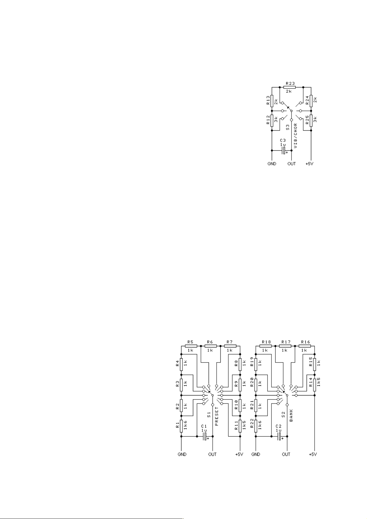
5.2.14 Native Instruments B4 chorus/vibrato #2140
Turning this pot will be reflected in B4 as "chorus/vibrato"
switch move. It has only 6 positions, and appropriate command
will be sent from MBBS to B4 every time the potentiometer
crosses each threshold representing another vibrato/chorus
mode. The circuit on the right shows proper B4 connection.
5.2.15 MidiTzer stops control - #2141
When assigned to a keyboard, each key becomes specific stop
controller. When a key is pressed, MIDI controller 81 (51 hex) is sent, and when it
is released, MIDI controller 80 (50 hex). Value of the controller is determined by
the button pressed. This is default way of controlling stops in MidiTzer organ
software.
5.2.16 Ahlborn Archive module stops control - #2142
If assigned to a keyboard, each key becomes stop control in Ahlborn Archive organ
sound-module. When a key is pressed, MIDI controller 73 (49 hex) is sent, when
released, MIDI controller 74 (4A hex). Value of the controller is determined by the
button pressed. This is default way of controlling stops in Ahlborn Archive module.
5.2.17 Ahlborn Organs stops control - #2143
When assigned to a keyboard, each key becomes specific stop controller in Ahlborn
Organs. When a key is pressed, MIDI controller 70 (46 hex) is sent with bit 6 of the
value set, and when it is released, the same MIDI controller but with bit 6 of the
value cleared. Other bits of the value are determined by the button pressed. In
another words, pressing the button sends CC 70 with value range 0-63, and
releasing a button - CC 70 with value range 64-127. This is default way of
controlling stops in Ahlborn Organs.
5.2.18 Program selector - #2144
Together with another pot configured
as in 5.2.19 this mode allows to
select one of 120 available MIDI
Program Changes (presets) by use of
2 rotary switches. Program selector
selects one of 12 Programs within a
bank. For better feel, you should
rather use 12-position rotary switch.
To do so, use the following
14
Page 15

schematics to build appropriate resistor network around the switch.
5.2.19 Bank selector - #2145
This mode works in combination with the one described in 5.2.18. A potentiometer
or switch assigned to this mode selects banks of 12 Programs. E.g. if it is in lowest
position, you can select any of Program numbers from range 1-12 using Program
selector described before. If you change the bank one position higher, Program
selector will then select programs from range 13-24, and so on, up until program
number 120. To use 10-position rotary switch instead of potentiometer, you must
add appropriate resistor network around the switch leads, as shown in schematics
above.
Bank selector and Program selector are useful only if you really want to select
programs by rotary switches, for example to match MIDI controller behavior to NI
B4 Hammond emulator, where bank selector works exactly like that. In typical case
you'd probably use different way of selecting programs, like "#4<number>
described in chapter 5.4.
5.2.20 Ahlborn Common Functions - #2146
When assigned to a keyboard, the buttons act in a way usable for group of controls
in Ahlborn module called "Common Functions" like general cancel, tutti, etc. It
works very much like mode 143 described in chapter 5.2.17. When a key is
pressed, MIDI controller 71 (47 hex) is sent with value 64-127, and when it is
released, the same MIDI controller but with value lower by 64.
5.2.21 3-note chord collect - #2147
This mode of operation is used only for keyboard scanners. You must play at least 3
notes at once to see any MIDI activity. When 3 notes are pressed, whole 3-note
chord is immediately sent. This assures that the chord is played clean, and it's not
spread in time. All additional notes (4th, 5th etc.) are played in MIDI right after
they are detected. This is especially usable in chord section of MIDI accordions,
where mechanically coupled switches do not always close in the same time.
5.2.22 Dual note (layered sound) - #2148
If assigned to a keyboard, every note played will be doubled in MIDI as 2 notes,
played in user selected channels and music interval. The settings of channel and
starting note of doubled (layered) channel are the same as used for upper split. So
in order to change defaults, you should first set the split at any point of the
keyboard
channel number)
(# 5 and any key)
and optionally change starting note of upper split
, then set the channel
(any key in upper split, # 3 and
(# 1 and one of
the 2 lowest key in the keyboard, which are actually located in lower split - see
chapter 5.1 for details)
the top key. Go to chapter 5.5 for details on split usage.
. When finished - cancel the split by setting its position to
5.2.23 One time velocity setup - #2149
This is similar to velocity settings described in 5.2.13, but in addition, it saves last
15
Page 16

used velocity settings in nonvolatile memory. This should be used only during
installation, when you want to set default velocity of notes after each power up. For
expression and frequent usage, control the velocity by assigning #2139.
5.2.24 Single keyboard transposition buttons - #2150 to #2153
A potentiometer, or special switch input can be assigned as setup buton for
keyboard transposition. There are 4 of them to choose and their event numbers are
150 to 153: one semitone up (150), one semitone down (151), one octave up (152)
and octave down (153). Pressing such button (shorting input to ground) will affect
only the last played keyboard, and this setting will be memorized in non volatile
memory. Go to chapter 5.1.2 for more details.
5.2.25 Channel set buttons - #2154 & #2155
MIDI channel of the last used keyboard or potentiometer can be changed in single
steps up or down, by using these special events. They can be assigned to any pot,
or special switch input. Event 154 rises the channel number of last played
keyboard, or last turned pot by one up, while event 155 does the same, but one
channel down. The settings are stored in non volatile memory.
5.2.26 All keyboards transposition - #2156 to #2159
This is similar to transposition setting described in chapter 5.2.24, also you can
have +/-1 semitone buttons (events 156 & 157), and +/-1 octave buttons (events
158 & 159). But there are 2 main differences. Here, transposition is set at once for
ALL keyboards in the system, regardless of what was played last, and this setting is
applicable only as long as the power is on. After power cycle, transposition returns
to initial settings, as adjusted by other means. This way of transposing is
recommended for performance control, where you may want to frequently shift all
keyboards. Go to chapter 5.1.2 for more details.
5.2.27 MIDI notes for stops control - #2160
In this mode keyboard plays normal MIDI notes, just like with standard note event
131 (chapter 5.2.5), but there are 2 differences: Global Transposition does NOT
affect this keyboard, and starting note number is 0, like other non-note events. This
is useful in organ emulators, where stops can be controlled by note-on/off
messages, but you really don't want the stops to change positions, every time
Global Transposition is used.
5.2.28 Reversed notes action- #2161
If keyboard's contacts are normally closed, and open only when key is pressed, you
may take advantage of this mode. If keyboard is assigned to reversed action, MIDI
note-on is sent when contact opens, and note-off when contact closes. There is no
need to short any unused inputs of keyboard scanner.
16
Page 17

5.3 MIDI Channel - #3
Channel of each potentiometer and keyboard or split can be set individually. To
change MIDI channel of certain potentiometer select the pot by simply turning it a
bit. Likewise, to select a contact scanner, play any note or flip any switch, whatever
is connected. Then you can select MIDI channel with the following sequence: "# 3
<channel number>". The channel number must be in range 1-16. Channels from 2
to 9 require only 1 key stroke, while channel 1 needs to be entered as 2 digits –
namely "01". Channel 10 and above of course need 2 keystrokes too. Then turn
another potentiometer or strike a key in other keyboard and select its channel the
same way.
Channel can be also set by +/- buttons if you assign any 2 potentiometer, or special
switch inputs in the system to proper events. They become then 2 inputs for
buttons, that change channel in steps one up or down for last used device in the
system, like keyboard or potentiometer. Go to chapter 5.2.25 for details.
There's also temporary channel shift control for all devices (keyboards and pots)
available if you assign event 136 for example to a small contact scanner like BBS24.
This way you can have direct inputs for selecting MIDI channel with single key
stroke. Go to chapter 5.2.10 for details.
5.4 Program Change - #4
MBBS allows to send Program Change MIDI messages in range 1-128. Several ways
are available, here's summary of them:
- series of Program Change buttons in continuous numbering range using event
129 described in chapter 5.2.3
- same as above but with each input programmable to a specific number, using
event 134 described in 5.2.8
- rotary switches for Bank and Program select described in chapters 5.2.18-19
It is also possible to select numbers greater than 128 with help of Bank Select MSB
message. This is exactly how patch select works in mode described here. To select
any patch number from range 1-999, you can use #4 command followed by the
patch number. To change the patch on selected keyboard directly to specific
number, play a note on this keyboard and enter the sequence: "# 4 <program
number>". The Bank Select and Program Change MIDI messages are sent directly
after 3rd digit of entered patch number. You must type 3 digits every time, even for
single digit program, like 001.
5.5 Keyboard split - #5
It is possible to split each keyboard into 2 independent parts. The split point can be
anywhere on the keyboard, and both parts can work with independently adjusted
MIDI channel, type of event and starting note (transposition) or range of other
controllers if something else than notes is assigned to a keyboard. Assuming that
all inputs of MBBS are equipped with DMS-2K dual keyboard scanner, it is possible
to make a system with 10 splits. To set up the split point, you have to select the
17
Page 18

keyboard by playing a note on it, and then enter sequence „# 5” followed by stroke
of the key that you want to be the top one of the lower part. Since then lower part
remains at the same channel that was used for whole keyboard, while upper part
takes settings of upper part, which by default is 5 MIDI channels higher. To change
MIDI channel, type of event, transposition, or send a Program Change for split
part, follow directions described before, regarding non-split keyboard, but now
changes are made only to the split last played before entering the edit mode.
To cancel existing split of a keyboard, as usual play any note on that keyboard, and
set the split for the top note like this: # 5 <top note>. This sets the end of 1st split
at the top note, so in fact the upper one is not visible anymore.
Channel and starting note settings of upper split are also used in dual note mode
described in 5.2.22.
5.6 Programming Patch Recall Buttons - #6
Whenever a program/patch/instrument selected from MBBS is often used, it is
worth to memorize as fast recall button. There can be 64 such buttons, working in
single MIDI channel. Those buttons can be connected to any keyboard scanner.
MBBS will send the patch number in channel previously assigned to all those
buttons with #3 command (see chapter 5.3.). To memorize any patch this way, you
have to first select this patch somehow by using any method described in chapter
5.4. Then simply press "# 6", and the key where the patch should be stored. Next
time whenever you press this key/button, the MIDI Program Change message will
be transmitted, with the number previously stored.
The number stored this way can only have range 1-128. If last selected program
was entered with #4 command, i.e. was greater than 128, the number memorized
will be the one from Program Change part, regardless of actual Bank Select used.
For example if patch 700 was selected as #4 700, actual number stored will be 700
modulo 128, that is 60.
To have Program Change memory in multiple channels, you may use multiple
keyboard scanners or splits, but total number of PC recall buttons must not be
greater than 64 in entire MBBS system. Also, if 2 or more scanners are used this
way, the same input in every scanner will generate the same Program Change,
although in separately defined channel.
18
Page 19

6 MIDI utilities
6.1 MIDI monitor - #971
MBBS board has one outstanding feature that helps during installation and
troubleshooting. You can use MIDI monitor if you have MiDisp - dedicated LCD
module (chapter 7.8). To activate this function, select #971, and the LCD will turn
red, showing "DEBUG MODE". Each activity on any scanner will be shown in the
display. Every time you press or release any key, or turn the potentiometer, the
display will indicate last transmitted data. The meaning of displayed values are:
● "D" - internal device number in the system
● "Ch" - MIDI channel
● "E" - event number as described in chapter 5.2.
● "S" - MIDI status byte in hex
● "V1" - value of 1st MIDI data byte in hex
● "V2" - value of 2nd MIDI data byte in hex.
MIDI monitor should not be enabled at all times, it increases MIDI latency and
may cause dropped or hung notes if LCD is connected in one chain with other
scanners. To turn off the MIDI monitor, enter #970 from the keypad. MIDI monitor
is always disabled at power-up.
6.2 Factory defaults - #979
MBBS has a lot of features to set and you may sometimes go one step too far, so it
may be useful to have last resort in form of factory defaults reset.
To do so, play any note on the keyboard connected to internal MBBS inputs and
enter command #979 either from the keypad if you have one, or from any contact
scanner, using lowest 10 keys as numbers from 0 to 9, in a way described in
chapter 5. About one second later MBBS is ready to use with all factory settings in
place. If MiDisp module is used, this process is clearly indicated at the display.
19
Page 20
7 Scanners
MBBS board is the merging point for all keyboard and potentiometer scanners.
Depending on their sizes, the whole system can cover up to 5 keyboards with 319
keys over single MIDI socket together with 64 potentiometers at the same time.
Currently available sizes are: 32, 64 and 128 keys, the last one has the 128 keys
grouped in 2 keyboards. For analog (pots) there are boards with 3 and 12 inputs
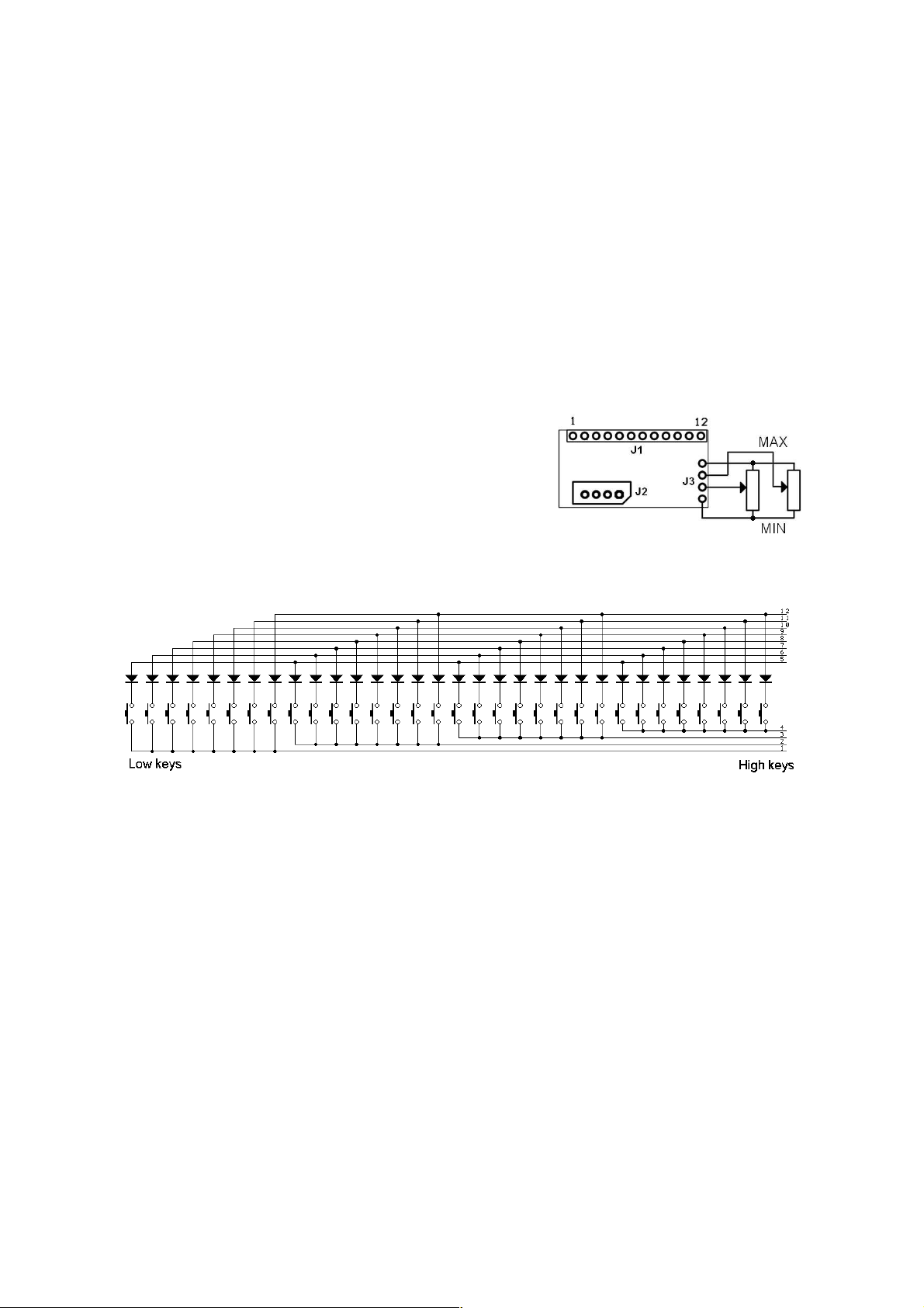
7.1 PDS - diode matrix pedal scanner
Pedal board controller takes care of 32 keys and two analog inputs, usually all
what's needed for pedals with 2 swell shoes. It's a small board that fits inside pedal
board, and it connects to the main board via
supplied 4-wire cable from J2 connector. 4 pads
labeled in this picture as J3, are for
potentiometers. The picture shows how to connect
the pots, and also in which pot position you get
the maximum, or minimum value of given MIDI
parameter controlled by the pot. Go to chapter 4
for more about potentiometer connection.
Keys must be connected in diode matrix exactly like in the schematics below:
The groups of 8 switches with 1 common lead must be separate. In case
of keyboard with 1 common bus bar going through entire keyboard, you
have to cut the bar every 8th key.
7.2 DMS-2K dual keyboard matrix scanner
For keyboards with diode matrix ideal solution is DMS-2K, adding 128 inputs. This
can be described as "diode matrix driver" for 2 keyboards. The layout is shown on
the next page. There are two 16-way connectors, used to connect diode-matrix
keyboards. Smaller connector is to connect with main controller board - MBBS. The
keyboards must have “8x8 scanning diode matrix”, that's very simple circuit, made
of diodes forming electric XY matrix. Usually all modern keyboards are equipped
with it although sometimes the matrix is organized differently, in 5x12 or 6x11. In
such case you must rewire the diodes, or order customized DMS-2K.
20
Page 21
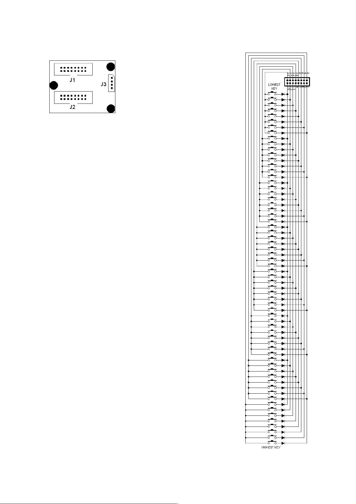
J1 – connector of 1st group of
keys (1 to 64)
J2 – connector of 2nd group of
keys (65 to 128)
J3 – connector linking this board to
the main board
Each 16-way connector covers one keyboard.
Schematic on the right shows example of diode matrix
compatible with DMS-2K board. Although this is default
matrix layout, DMS-2K can be reconfigured by the user to
work with 4 different diode matrix types. It must be 8x8 but
can have different order of notes. The only requirement is
that cathodes are connected to odd pins of DMS-2K
connector, and anodes to even pins. Either directly or via
key switch. If, after the keyboard is connected, the order of
keys is not correct, you can try one of the 4 modes of DMS2K operation in the following way:
1. play any note on a keyboard connected to DMS-2K
2. enter EDIT mode either by pressing "#" keypad
button or by shorting to GND the 64th pin on MBBS
board
3. enter "92" from numeric keypad or internal MBBS
contact inputs (pin 10th and then 3rd)
4. enter one digit from range 1-4 the same way as you
entered "92". Each digit turns the scanner into
different one of 4 modes of how notes are ordered.
5. play the DMS-2K keyboard to check if it is OK now.
If not, start from the beginning, but now select
different digit from range 1-4 in step 4.
7.3 BBSP - common ground pedals
scanner
This one is especially suitable for small keyboards (or
pedals) with single wire used as common bus for all
switches in entire keyboard. This one does not use diode
matrix, and can be used with almost any type of switch
arrangement, it can also be controlled by logic gates. Apart
from contacts it also has 3 analog inputs for
potentiometers, that can be used in swell/crescendo pedals.
Keyboard is connected to 2 16-pin connectors - J1 and J2
shown below. Each of them covers 16 keys. Potentiometers
connect to 5-pin header at the right hand side of the board,
21
Page 22
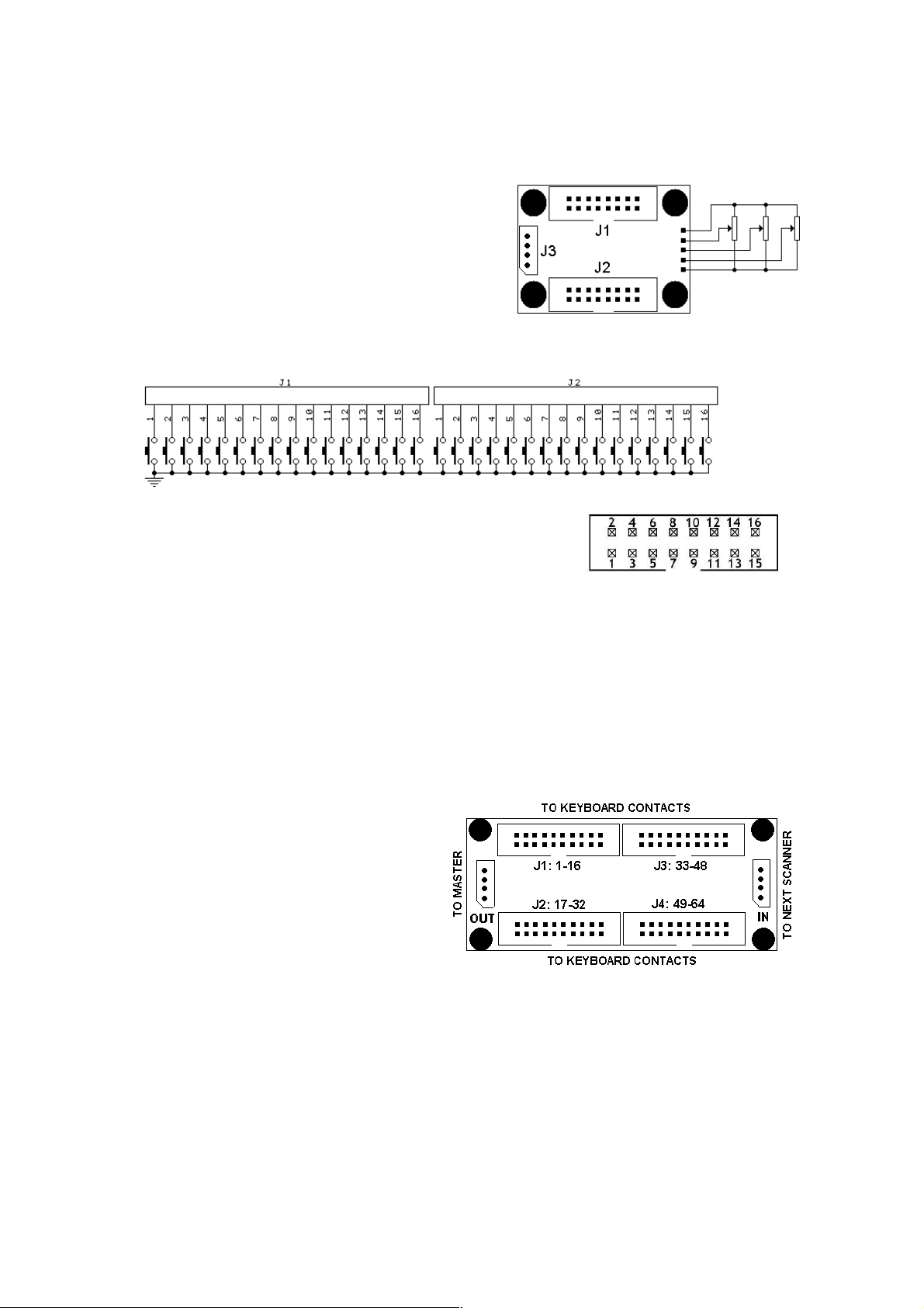
according to the diagram below. See chapter 4 for more info on potentiometers
usage.
The key contacts must use one common buss
bar (with GND), or logic IC may control BBSP
inputs. 0V at an input means “key pressed”,
+5V at input or left open means “key
released”. Keyboard should be connected to
two 16-pin headers according to the diagram
below.
Works best with 2 IDC plugs and 16-wire ribbon cable, ordered separately.
Each black connector holds 16 inputs for keyboard
switches. The pin numbering within one connector is
shown here. Notice orientation of the keying slot. This
pinout is valid for every 16-pin connector in every board.
7.4 BBS-1K common ground keyboard scanner
This board is mainly used as a scanner of 5-octave keyboard. It has 64 contact
inputs, and daisy-chain input, so you can use 2 such boards connected to 1 MBBS
input. All 4 connectors for ribbon cable and the pinout are the same as used in
BBSP - see above. Each black connector covers 16 keys. BBS-1K must be connected
towards the MBBS with 4-way connector indicated "OUT". The connector marked
"IN" is for the purpose of adding
next optional scanner. There can be
only 2 keys scanners (BBS-1K, BBSP,
DMS-2K, PDS, LITSW) in one chain.
If third keyboard scanner is chained,
it will work like paralleled inputs of
2nd keyboard in the chain.
7.5 BBS24 little scanner for contacts & pots
This one is especially suited for the bass/chord part of MIDI accordions. It works
with 24 switches, and 3 analog sources like pots, or voltages e.g. from pressure
sensor. If split is set in the middle (chapter 5.5.) 12 inputs can be assigned to
basses, and 12 to chord contacts in accordion and play in different channels. The
board is small enough to put it inside bass/chord part of an accordion. Unlike other
22
Page 23
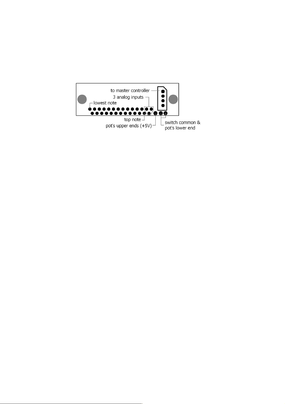
scanners, all user inputs are bare pads to solder wires. This further reduces space
required for installation, because typical IDC headers would be too big. Of course it
may work in any other instrument/controller requiring limited (24) number of
contacts, and up to 3 potentiometers. The diagram below describes all connections
to BBS24.
7.6 LITSW - button scanner with LED drivers
LITSW is the controller for lighted switches. It has 24 inputs for contacts, and 24
outputs for LEDs associated with them. Currently available modes of operation for
this board are:
1. independent registers ("check boxes"), where each button click lights up or
darkens the LED, and proper MIDI message is generated according to MBBS
setting for that scanner. If this is MIDI note, a note-on is generated at LED
turn-on and note-off when LED turns off. If it is Program Change, only one
event is generated, when the LED turns on
2. dependent choice ("radio buttons"), where only one LED-button can be
active (lights up). Pressing any other button causes previously lighted to turn
off, and the one pressed lights up now. If assigned to notes, only MIDI noteon is generated, this is more suitable for use with Program Change
3. contact on/off mode, where button action is recognized as typical contact
scanner (BBS). So all kinds of MIDI events applicable to a keyboard are also
possible here giving predictive results.
4. CC value mode, where LITSW works like potentiometer scanner, but with
only min and max values. The advantage of this mode is that you can assign
totaly different MIDI channel and event to each button.
5. bank/select, useful for preset selectors. In this mode LITSW must be split in
2 parts. One is serving as bank select, the other one - as program select. If
the split is made on 10th key, lower split is representing units of given
Program number, and the upper one - tens of this number. Of course it
makes more sense when MIDI event 129 is assigned to that LITSW (that's
Program Change)
It is possible to select more than one mode at once, although not always it makes
sense. For example modes 1-2, as well as 3-4 are mutually exclusive, but you can
set for example modes 1, 3 and 5 together. The mode of operation can be assigned
to all buttons or differently to each of the 2 splits if it was divided (chapter 7.6.1.)
23
Page 24
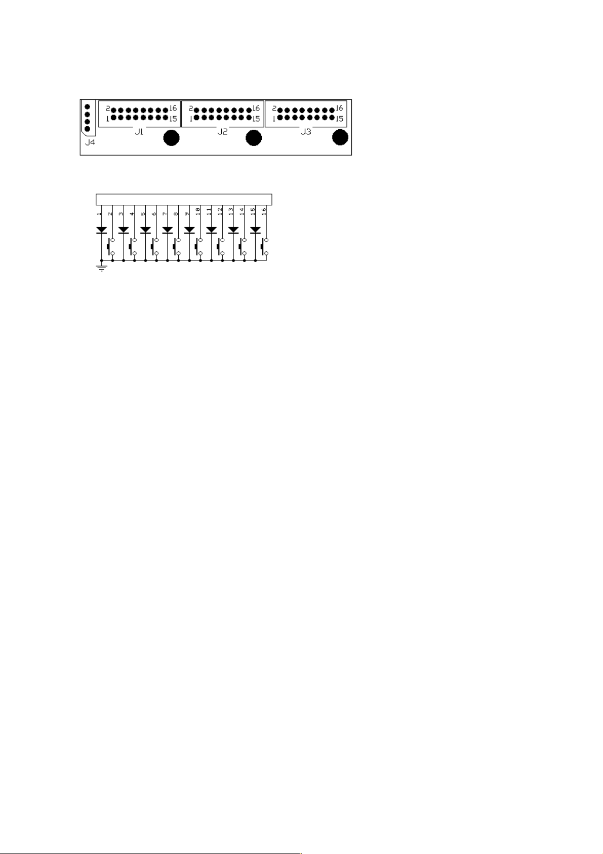
J1 - LED-buttons 1-8
J2 - LED buttons 9-16
J3 - LED buttons 17-24
J4 - connector to MBBS
The pins of each LED-button connector are
interlaced for easier installation. Odd pins
are LED outputs, and even pins are button
inputs in the following manner: pin 1 - LED
1, pin 2 - button 1, pin 3 - LED 2, pin 4 button 2, etc. This is shown in the
schematic on the left. Each 16-pin
connector layout is the same.
Out of the box it generates note-on and note-off messages with momentary
buttons and LEDs (independent mode), most useful as register control in organ
emulator. But it can be converted into a few variations, finding its way toward other
non-typical uses. Possible controls are:
7.6.1 Split point - #905
This is different kind of split than the one described in chapter 5.5 and is
independent of that one. So you can use both kinds of split at one time, and they
can be at different points, even though it may not make much sense. The
split controls only button's behavior, and not actual MIDI data transmitted by MBBS
to MIDI OUT socket. Each split can work in different mode, with independent or
dependent buttons, generating CC values or contact on/offs. To have different MIDI
events or channels in the splits you have to also split it logically, using procedure
described in 5.5.
#905
7.6.2 Independent mode - #908
In independent mode, all buttons work without interactions to each other. If a
button is pressed, associated LED lights, and note-on is sent by MBBS (only if it is
configured to send notes on this input - sequence #2131). Another touch of this
button and LED turns off and note-off is sent. To set this mode on a split, you have
to select it first by pressing one of the buttons in that split.
7.6.3 Dependent mode - #909
In dependent mode, there can be only one LED active at a time. If you press
another button, it will light up and any one that was previously lit, will now turn off.
In this mode only note-on messages are generated, there is no note-off. This is
most useful for selecting presets on MIDI instrument, like described in chapters
5.2.3., and 5.2.8. To set this mode on a split, you have to select it first by pressing
one of the buttons in that split.
24
Page 25

7.6.4 Bank/preset select - #910
This mode requires prior split of the LITSW keypad sequence #905 described in
chapter 7.5.1. If you then type #910 on the keypad, LITSW board will work as
patch selector with separate row of "banks" buttons and "presets" buttons. If the
split is made after 10 keys, lowest 10 buttons will act like preset selector within a
bank, and all buttons above 10 - as bank selectors. Although it is possible to use
this mode with independent buttons, described in 7.5.2, most obvious use is
together with dependent butons mode described in 7.5.3. To use it as Program
Change selector, you should program appropriate MIDI event on this input, which
for Program Change is - #2129. The split point doesn't have to be after 10 buttons.
It can be e.g. after 6 buttons. Then first bank will select patches from 1 to 6,
second bank from 7 to 12 etc.
7.6.5 Disable bank/select mode - #911
To disable bank/select mode described above, you must type #911 sequence on
the keypad. It then returns to normal mode, where each button in both splits have
constant value, regardless of what was pressed in the other split.
7.6.6 Contact on/off (keyboard scanner) mode - #912
This is normal way of operation for this scanner. When a button is pressed, MBBS
can then generate MIDI notes, or any other MIDI event usable with a keyboard
scanner. This is the oposite to CC value mode described next. To set this mode on a
split, you have to select it first by pressing one of the buttons in that split.
7.6.7 CC value (pot scanner) mode - #913
In this mode LITSW works a bit like potentiometer scanner. When button is on, it
simulates turning a potentiometer to a maximum, and when the button is off (LED
is turned off) it resembles a potentiometer turned to minimum. So it's like 24 pots
with only 2 valid positions: min and max. This is useful for switching parameters in
virtual instruments, e.g. Hammond emulators. For each button you can assign
individual MIDI event (like CC or anything else) and MIDI channel. To set this mode
on a split, you have to select it first by pressing one of the buttons in that split.
7.6.8 Left split blink - #916
When you type this sequence on a keypad, LITSW will blink all LEDs in lower split
of LITSW. This can be used to determine where the split point is, and where are
the LEDs connected.
7.6.9 Right split blink - #917
When you type this sequence on a keypad, LITSW will blink all LEDs in upper split
of LITSW. This can be used to determine where the split point is, and where are
the LEDs connected.
7.6.10 All LEDs blink - #918
When you type this sequence on a keypad, whole LITSW will blink all LEDs. This
25
Page 26
can be used to see if every LED is connected properly and where they are located.
7.6.11 Reset to defaults - #929
If your LITSW has been set with a strange combination of modes, it may be useful
to return to the state where it was as it came out of the box. To do so, press any of
the LITSW buttons, and enter command #929. LITSW then returns to factory
defaults, which is independent mode, no split, and keyboard scanner mode. This is
confirmed with short blink of all LEDs. This is available since LITSW version 2.8
7.7 POT12 - potentiometer scanner
POT12 adds 12 potentiometers to MIDI system built
around MBBS. It has one 14-pin black connectors for
potentiometers, and 2 small 4-pin sockets, typical for all
midi-hardware.com MIDI board. The one indicated
"OUT" is used to connect the to the MBBS. The other
one can be used to connect another scanner, be it
keyboard or another POT board. If you reverse connections between those 2
sockets, the board will not work, and potentiometer movement will not result in any
MIDI activity. However this does not cause any damage to the POT12 board.
You can chain up to 5 POT12 scanners and make 60 inputs for the whole system.
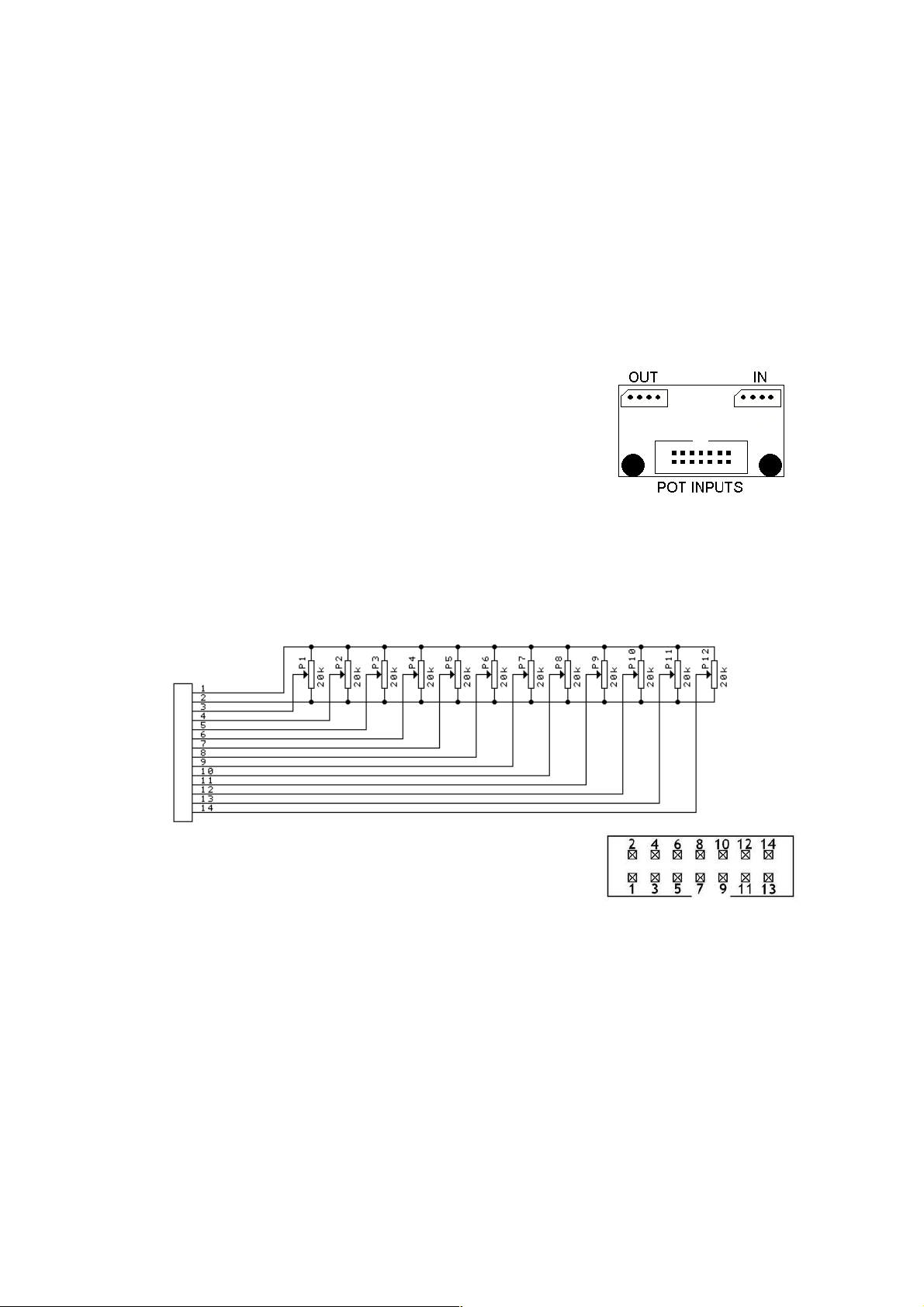
The bigger black connector holds potentiometer inputs. Its connection is shown
here:
The black connector holds 12 inputs for pot wipers, and 2
for top and bottom taps. The pin numbering within one
connector is shown here. Notice orientation of the keying
slot.
If you don't use all potentiometers you may want to connect unused inputs to VCC
(pin 1). Keeping any, or all inputs open is quite safe, but in some cases
may result in unexpected MIDI messages. That's most likely to happen with
fast response settings described in chapter 4.1. With fast update rate and inputs
left open, moving one potentiometer may trigger unexpected other MIDI messages.
In such cases it is enough to connect all unused inputs to VCC (pin 1 or 11 of each
black connector) and spurious messages will never appear again.
26
Page 27

7.8 MiDisp - 2x16 characters display
MBBS boards have lots of useful features, and all are available to the user without
need of any PC or custom programmer. Simply because there are so many
parameters, it may sometimes become difficult to follow every setup procedure
without any clear indication what is happening. To help in user settings and add yet
another functionality, you may use MiDisp module, with the following features:
● one input for external switch, assignable the same way as any other scanner
● text messages indicating every stage of user settings
● backlit color changing depending on current EDIT, or other modes
● MIDI monitor useful when checking communication
MiDisp module can be connected anywhere in the system, directly to MBBS, or in
the chain with other scanners. There may be several MiDisp modules connected to
one MBBS master controller, but due to power limitations there should be no more
than 5 display modules in one system. To have more, you should use power
booster available on request. Only one MiDisp will become system display during
startup. It will show all EDIT messages and MIDI monitor. Other displays may be
used only as 1-button controls with visual indication. To maintain full compatibility,
you should use MiDisp in version 1.4 or later.
You may change the way how MiDisp operates to some extent. To do any settings
on particular display module, you must select it first, and the only way of doing that
is to press the button connected to MiDisp button input (or simply short those 2
pads temporarily with a piece of wire). The pads to connect MiDisp button are
located at the back of it and are clearly indicated. More general guidelines about
entering commands can be found in chapter 5.
Possible controls are:
7.8.1 Toggle mode - #908
In toggle mode, the module works like bistable (SPDT) switch. If a button is
momentarily pressed, the display shows "ON" and turns white. Appropriate MIDI
message is sent via MBBS's MIDI OUT. Another button press, and display turns
blue, showing "OFF", and another MIDI message is sent. You can assign completely
different MIDI events and channels for "ON" state and "OFF" state, like described in
chapters 5.2. and 5.3. Both states work like potentiometer action, but the value is
always the same, determined by device ID, see 7.8.3 for details.
7.8.2 Momentary mode - #909
In momentary mode, it works almost like a keyboard. It is useful if you want to
connect mechanical toggle switch. Apart from momentary action, all other
functionality is exactly like in toggle mode - ON state generates different event than
OFF state, and can be programmed.
7.8.3 Display ID set - #914
Each MiDisp in the system has individually set parameter called "Display ID".
Currently it is used only as value for on/off events of the button connected to
27
Page 28

MiDisp. To change display ID, you have to select the display by pressing its button
first. Then enter command #914, and the display will show current device ID,
waiting for new digits. Possible values are from 00 to 99. This parameter is
associated with the display itself, and does change when you replace the module to
another MBBS input, or another position in a chain.
7.8.4 Display ID show - #920
You can check display IDs of all MiDisp modules in the system at once. First you
have to press a button of any LCD in the chain, and then enter command #920.
Then all displays connected to MRG will show their current display ID.
7.8.5 Display blink - #918
This is simply to make the MiDisp blink for a while. If you have chain of displays,
they will blink in a sequence determined by their position in the chain.
7.9 KEYPAD - numeric entry for user MIDI settings
Small keypad, resembling the ones used in phone sets, is all you need for changing
every setting available in MBBS. When not in edit mode, buttons 0-9 work exactly
like any music keyboard, playing notes if default setting was not changed. Button
"#" works like the last (64th) pin in contacts connector on-board MBBS. It brings
the system in EDIT mode. If MiDisp module is connected, it is clearly indicated
there. To quit from EDIT mode without changing anything, for example if "#" was
pressed by mistake, simply enter "0". There's no command starting with 0, so it
immediately returns to normal playing mode.
The KEYPAD, as setup entry, does not have to follow the rule of "only 2 keyboards
in a chain". It may be connected at the end of 2 BBS-1K chain and it will work
correctly. The channel, event, and starting note of the KEYPAD will be the same as
2nd BBS-1K in the chain, but this in any way des not disturb the KEYPAD in correct
function as setup keypad.
The electronic board mounted at the back of the keypad (since version 7.0) allows
to connect one rotary encoder, called sometimes "endless potentiometer". It is
treated like any other POT input, meaning it can be assigned to any possible event.
Most obvious use for example is Program Change knob (event 129), but it may be
global transposition, channel shift, or simply any Continuous Controller.
The encoder used must have no detents, or 2 detents per pulse. If 1 detent per
pulse is used, every step of the encoder will result in 2 MIDI messages, crossing 2
steps. The encoder must be soldered to 3 empty pads by the side of 4-way scanner
connector. Pinout is the same as in encoder itself, with common lead at the middle,
and pulse inputs at the sides.
28
 Loading...