

Page 1
This service manual is not available to the general users, but only applies to professional
technicians with relevant qualifications. Any incorrect maintenance may result in other
dangers!
The power and gas supply must be cut off before maintenance!
A new power cord which meets the relevant technical requirements must be used once
possible hidden malfunctions are found with the current power cord (refer to this
Manual)!
Please read carefully all safety warnings in this Manual before maintenance!
The product is prohibited from using until test is conducted as per relevant regulations
after maintenance!
This service manual applies to many models, so the specific operations please prevail in
kind!
Service Manual For Free-standing Oven
( 90X60 Gas COOKTOP and Electric oven )
Warnings
V2.0
Mar, 2014
Page 2

Contents
1. Precaution .................................................................................................................................................................. 1
1.1. Safety Precaution ................................................................................................................................................ 1
1.2. Warning ............................................................................................................................................................... 1
2. Dimension................................................................................................................................................................... 1
3. Function ...................................................................................................................................................................... 2
3.1 Flame thrower function............................................................................................................................................ 2
3.2 Oven function ........................................................................................................................................................... 2
4. Attention .................................................................................................................................................................... 3
5. Circuit diagram ........................................................................................................................................................... 4
6. Disassembly ................................................................................................................................................................ 5
6.1 Disassembly of cooktop ........................................................................................................................................ 5
6.2 Disassembly of knob .............................................................................................................................................. 6
6.3 Disassembly of drawer .......................................................................................................................................... 7
6.4 Disassembly of oven door ..................................................................................................................................... 7
6.5 Overview of inside structure ................................................................................................................................. 8
6.6 Disassembly of heating element(upper) ............................................................................................................... 9
6.7 Disassembly of heating element(bottom)........................................................................................................... 11
6.8 Disassembly of oven lamp ................................................................................................................................... 12
6.9 Disassembly of rotary motor ............................................................................................................................... 13
7. Troubleshooting ....................................................................................................................................................... 15
7.1 Gas troubleshooting ............................................................................................................................................ 15
7.2 Electronics troubleshooting ................................................................................................................................ 16
8. Maintenance and test .............................................................................................................................................. 17
8.1 Air leakage test .................................................................................................................................................... 17
8.2 Replacement of injector and adjustment of valve .............................................................................................. 18
8.3 Replacement of valve body ................................................................................................................................. 19
8.4 Replacement of gas-type fitting .......................................................................................................................... 19
Page 3
1. Precaution
1.1. Safety Precaution
1. To prevent injury to the user or other people and property damage, the following instructions must
be followed.
2. Incorrect operation due to ignoring instructions will cause harm or damage.
3. Before maintenance, please read carefully the following instructions at first.
1.2. Warning
1. The power cord shall be replaced withan insulation power line which is no less than AWG*2
+AWG10*1 and resists temperature of greater than 60℃.
2. All apparatus within a radius of 50mm from this product must resist temperature of greater than
75°C, otherwise, deformations are easily to be caused during the application process of this product.
3.When the wrapping materials are removed, keep such materials like metal sheet, packingbag, foam
and screws out of reach of children’s reach to avoid potential dangers. For example, the children
may suffocate as a result of swallowing tiny components or playing with packing bag
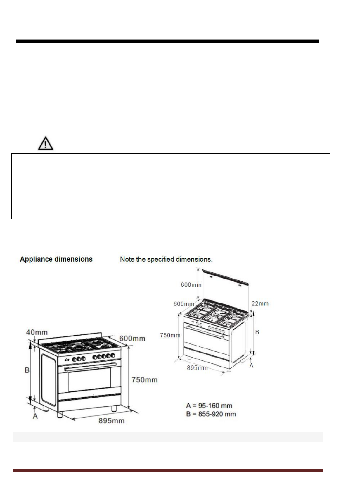
2. Dimension
Note: Dimensions for reference only.
Page1
Page 4
3. Function
Function
Power
lamp
96W
Fan
162W
heating element (upper)+infrared element+fan+rotary barbecue+lamp
2966W
heating element (upper)+ infrared element + rotary barbecue+lamp
2900W
infrared element + rotary barbecue+lamp
1900W
heating element (upper) + heating element (bottom)+ fan+lamp
2862W
heating element (upper) + heating element (bottom) +lamp
2796W
heating element (bottom) +lamp
1796W
Heating air+lamp
2562W
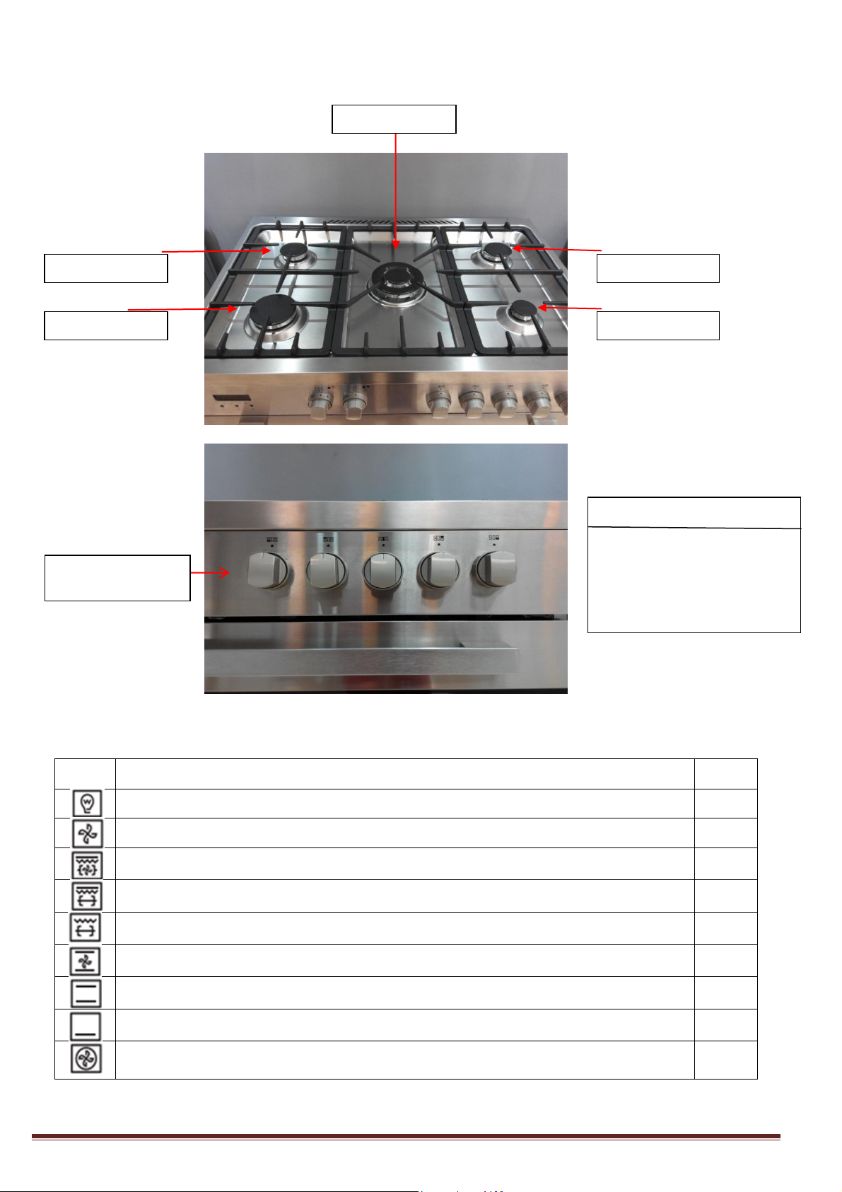
Flame thrower 1
Flame thrower 2
Flame thrower 3
Flame thrower 5
Flame thrower 4
Switch 1~5
(from left to right)
One-to-one match
Switch 1 ~Flame thrower 1
Switch 2 ~Flame thrower 2
Switch 3 ~Flame thrower 3
Switch 4 ~Flame thrower 4
Switch 5 ~Flame thrower 5
3.1 Flame thrower function
3.2 Oven function
Page2
Page 5
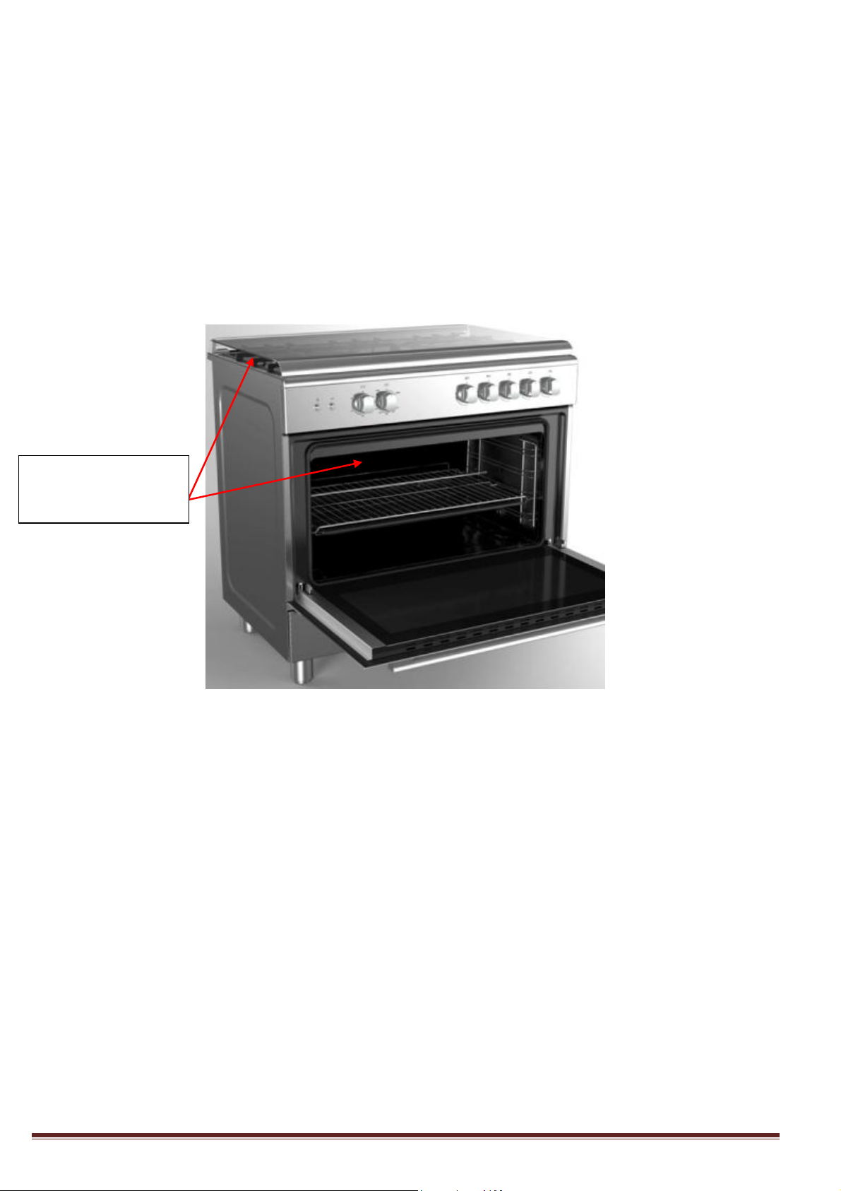
4. Attention
Hand holding
position when oven is
moved
The oven door shall be opened to contact the upper part and back of the oven cavity if the oven is
required to be lifted or moved. It is prohibited from using door handle directly to lift the oven(see the
following figure).
All inflammable, combustible and non-heat resistant articles shall be kept away from the surrounding of
the oven.
The ground shall be maintained flat enough for placing the oven to ensure sufficient stability of the
product.
Page3
Page 6
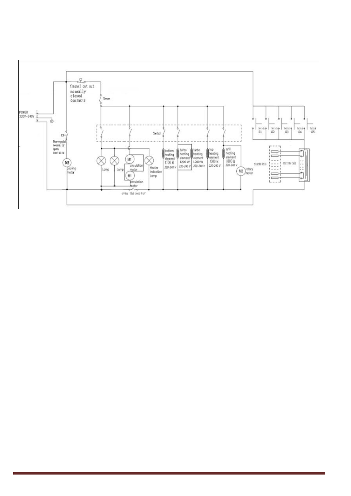
5. Circuit diagram
Circuit diagram for gas oven
Page4
Page 7
6. Disassembly
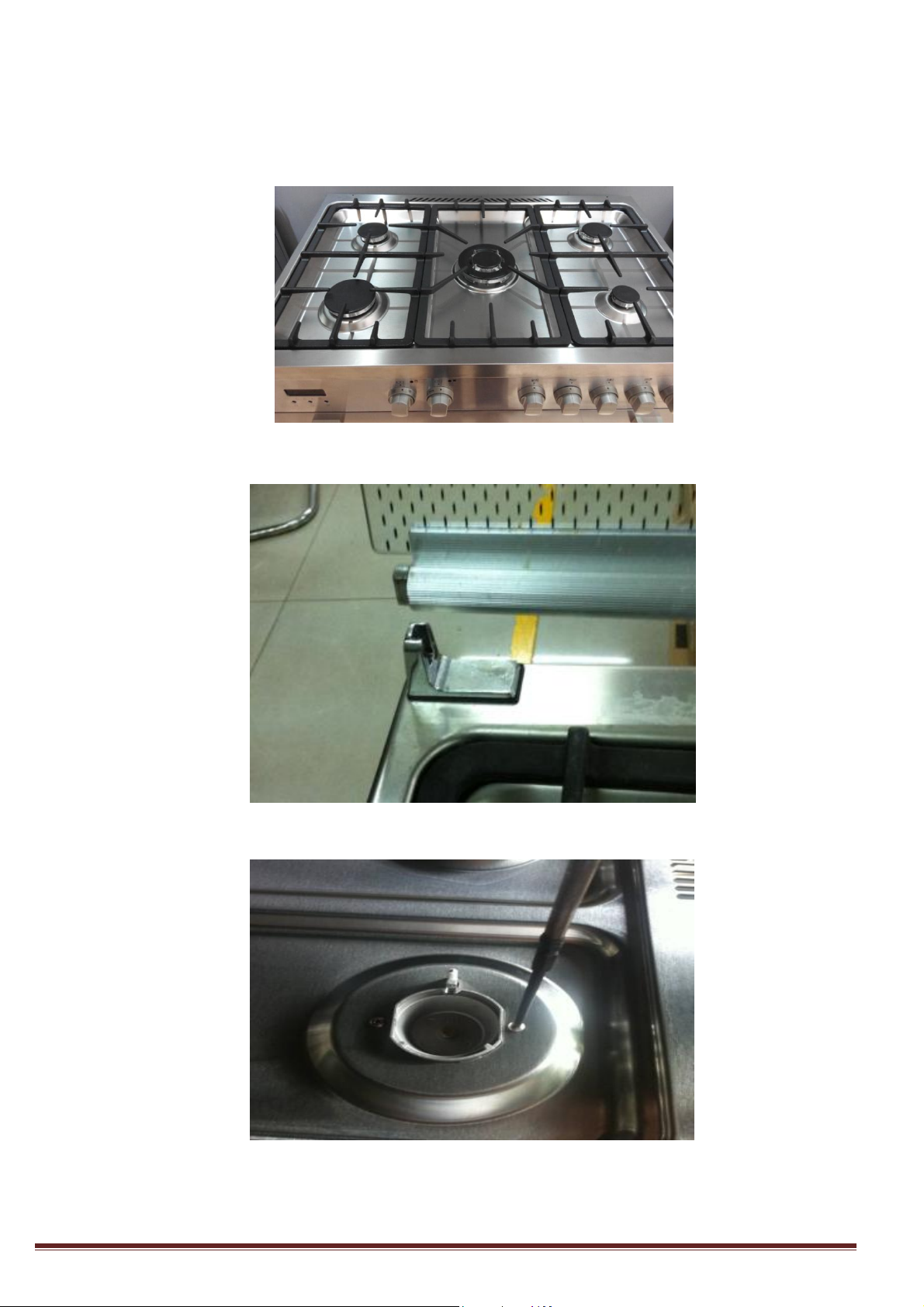
6.1 Disassembly of cooktop
Step 1: Remove the pan supports, sprayers and burner caps on the cooktop.
Step2: Remove the cook top lid
Step 3: Unscrew the screws used on the burner cup
Page5
Page 8

Step 4: Unscrew rear section.
Screw
1.PUSH UP
2.PUSH FORWARD
Step 5: Lift the rear of cook top gently and push forward to front.
6.2 Disassembly knob
Step 1: Lift the knob base and pull it out.
Page6
Page 9

6.3 Disassembly of drawer
Step 1: Open the drawer to a maximum angle.
Step 2: Remove the four screws attached to the drawer hinge with a screwdriver.
6.4 Disassembly of oven door
In reference to the instruction manual “Removing and fitting the appliance door”.
Page7
Page 10

6.5 Overview of inside structure
Valve body *5
The main gas tupe
Bottom cup*5
Flame ignitor
Rotating motor
Thermo switch 55℃
normal open
Heating element (upper)
Lamp
Terminal block
Rotating motor
Heating element
(Bottom)
Cooling motor
Picture 1.Inside structure
Page8
Page 11

Heater Terminals
screw
6.6 Disassembly the heating element(upper)
Step 1: disassembly the rear panel.
Step 2: Pull out the terminal of upper heating element.
Page9
Page 12

Step 3:Open the door, take out the Cooking grid ,Cooking grid(with cooking pan) and cooking pan.
Screw
cooking grid
cooking grid
(with cooking pan)
door
cooking pan
Step 4:Unscrew four screws, take out the heating element(upper)
Page10
Page 13

6.7 Disassembly the heating element(bottom)
screw
Screw
Step 1: Disassemble screws, open the rear panel.
Step 2: Pull out the terminal, unscrew the bracket of heating element(bottom).
Page11
Page 14

6.8 Disassembly of oven lamp
Lamp wire
Ground wire
Bulb cover
Bulb
Step 1: Disassemble the cooktop and pull out the lamp wire and ground wire.
Step 2: Remove the bulb by screwing the bulb cover off the cavity only if the bulb is required to be replaced.
Page12
Page 15

6.9 Disassembly of rotary motor
wire harness
Step 1: Disassemble the control panel.
Step 2:Ddisassemble the left side board to expose the rotary motor.
Step 3: Pull out the wire harness on the rotary motor.
Page13
Page 16

Step 4: Remove the rotary motor and loosen the fixed screws at both ends of the rotary motor support.
screw
Page14
Page 17

7. Trouble shooting
Phenomenon
Inspection method
Repair measures
(I)The burner is detected with
yellow flame.
1 Examine if the gas source of the
product is in conformity with the
application requirements;
2 Examine if the gas pressure is in
conformity with the application
requirements;
Please turn to Inspection method
(II)The burner flames out.
Examine if the gas source of the
product is in conformity with the
application requirements;
(III) The burner cannot be
ignited easily;
1 Examine if the gas source of the
product is in conformity with the
application requirements;
2 Examine if the gas pressure is in
conformity with the application
requirements;
3 Check if the ignition holes of the
burner are blocked or detected with
burrs;
4 Check if the fire-conductive leaf
overlaps with the flash hole;
Replace or adjust
(IV) No suction of flame-out
protection valve and
temperature controller valve
1 Check if the flame ignites the
thermocouple;
2 Check the joint between
thermocouple and electromagnetic
valve for any loosening and if the
connecting wire of the
thermocouple is cut off;
3 Adjust the distance between the
head of thermocouple and the
burner to 2mm to 4mm.
thermocouple
7.1 Gas trouble shooting
Page15
Page 18

Phenomenon
Cause
Solution
(I) The heating elements are
not heated.
1 The heating element is damaged.
2 Wire fault(open circuit)
3 Failure on heating element control switch
1 Replace the heating element
2 Change the wireharness
3 Change the control switch
(II) The oven lamp cannot be
light up
1.The oven lamp is damaged;
2.Wire failure
3.Failure on lamp control switch
1 Replace the oven lamp
2 Change the wireharness
3.Chnage the lamp control switch
(III) The ignition needle can
not strike fire.
1 The pulse igniter is damaged;
2 The ignition needle is damaged or ill
contacted;
3 Wire failure
4 Failure on ignition control switch
1 Replace the pulse igniter
2 Replace the ignition needle
3 Change the wire harness
4 Change the ignition control switch.
(IV) The rotary motor did not
rotate at all.
1 The rotary motor is damaged.
2 Wire failure
3 Failure on rotary control switch
1 Replace the rotary motor
2 Change the wire harness
3 Change the rotary control switch
Note!
1 Check the ground wire before the fault is detected;
2 Enough attention must be given to high voltage circuit.
7.2 Electronics troubleshooting
Page16
Page 19

8. Maintenance and test
Smear with suds-immersed
fabric each joint of the gas
pipe lines and check visually
for any air bubbles.
8.1 Air leakage test
Tool: Air leakage device, soap water
1. Professional repair procedures
a) Connect product to the air leakage device and set the test pressure at 15kPa;
b) The plug valve shall be kept closed and the gas pipelines may be tested its leakage through air leakage
device;
c) All plug valves shall be kept open, block the injector at the burner, the flame-out protection valve is kept
open and the gas pipelines may be tested their leakage through air leakage device.
The leakage must be controlled below 0.5mL/min as required in the test.
2. Simple procedures:
a) Connect the product to the gas being used;
b) Smear soap water at each joint of the product gas pipelines, the plug valve is kept closed, check visually
each joint for air bubbles;
c) Smear soap water at each joint of product gas pipelines, all plug valves shall be kept open, the injector of
the burner shall be blocked, the flameout protection device valve shall be kept open and check visually
for any air bubbles;
No air bubbles shall be detected at each joint as required in the test.
Note: Any component of the product gas pipelines shall not be disassembled or replaced only if the air
leakage is proved in conformity with relevant requirements.
Page17
Page 20

8.2 Replacement of injector and adjustment of valve
烤箱换喷嘴
调阀
Comparison list forinjectorreplacement
Change the injector
Replace the injector in the oven
Adjustable valve
Tool: Inner hexagon S7 sleeve/straight screwdriver of 2mm diameter
Steps for operation:
a) Disassembly respectively the cooktop, the injectors of upper and lower burners with sleeve.
b) Get a corresponding substitute injector(see the following table), apply thread sealant around its screw
thread and reassemble with sleeve.
c) Switch on the gas source, ignite corresponding burner and turn to small fire mode;
d) Pull out the knob, use screwdriver to enter from the small holes on the valve stem, adjust the core of
valve and observe the size of flame until moderate small flame is seen(the flame envelope is 4mm higher
than the burner); Adjust the fire of lower burner until moderate small fire is seen and no flameout as the
door is being closed.
Page18
Page 21

8.3 Replacement of valve body
Gas tube
Joint
Seal washer
Disassembly (assembly) aluminum gas tube
Disassembly (assembly) aluminum gas tube
Tool: screwdriver, open spanner
Steps for operation:
a) Disassembly the thermocouple connected to the valve body;
b) Disassembly the aluminum gas tube connected to the valve body with open spanner (see the picture);
c) Unscrew the screws on the mounting valve with screwdriver
d) Assembly a replaceable valve onto the product by following a reverse order of above mentioned
procedures and connect aluminum gas tube and thermocouple.
8.4 Replacement of gas-type fitting
Tool: open spanner
Steps for operation:
a) Disassembly the gas-type fittings from main gas tube with spanner.
b) To replace gas-type fitting ,note to lock tightly onto the main gas tube.
Page19
 Loading...