

Page 1

Midea R410A Direct Heating Commercial Heat Pump 50Hz Technical Manual MCAC-HTSM-201506
1
Midea R410A
Direct Heating Commercial Heat Pump
50Hz
Technical Manual
Applicable Model:
RSJ-420/SZN1-H
RSJ-800/SZN1-H
Midea reserves the right to discontinue, or change specification or designs at any time without notices and
without incurring obligations.
Page 2

MCAC-HTSM-201506 Midea R410A Direct Heating Commercial Heat Pump 50Hz Technical Manual
2
Content
Part. 1 General information ............................ 3
Part. 2 Performance ........................................ 5
Part. 3 Installation ......................................... 26
Part. 4 Controller ........................................... 62
Page 3

Midea R410A Direct Heating Commercial Heat Pump 50Hz Technical Manual MCAC-HTSM-201506
3
Part. 1 General information
1. Model Names of Units ........................................................... 4
2. External Appearance ............................................................. 4
3. Nomenclature ....................................................................... 4
Page 4
MCAC-HTSM-201506 Midea R410A Direct Heating Commercial Heat Pump 50Hz Technical Manual
4
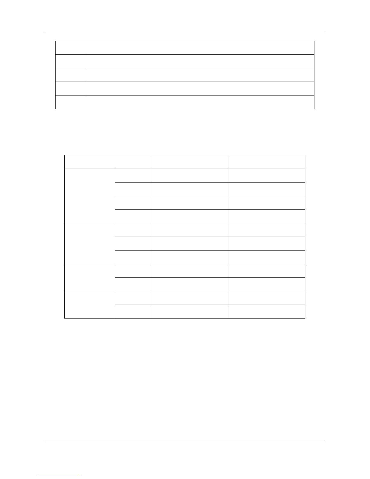
1. Model Names of Units
Model
Power supply
Direct-heating Type
RSJ-420/SZN1-H
380-415V~, 3Ph, 50Hz
RSJ-800/SZN1-H
380-415V~, 3Ph, 50Hz
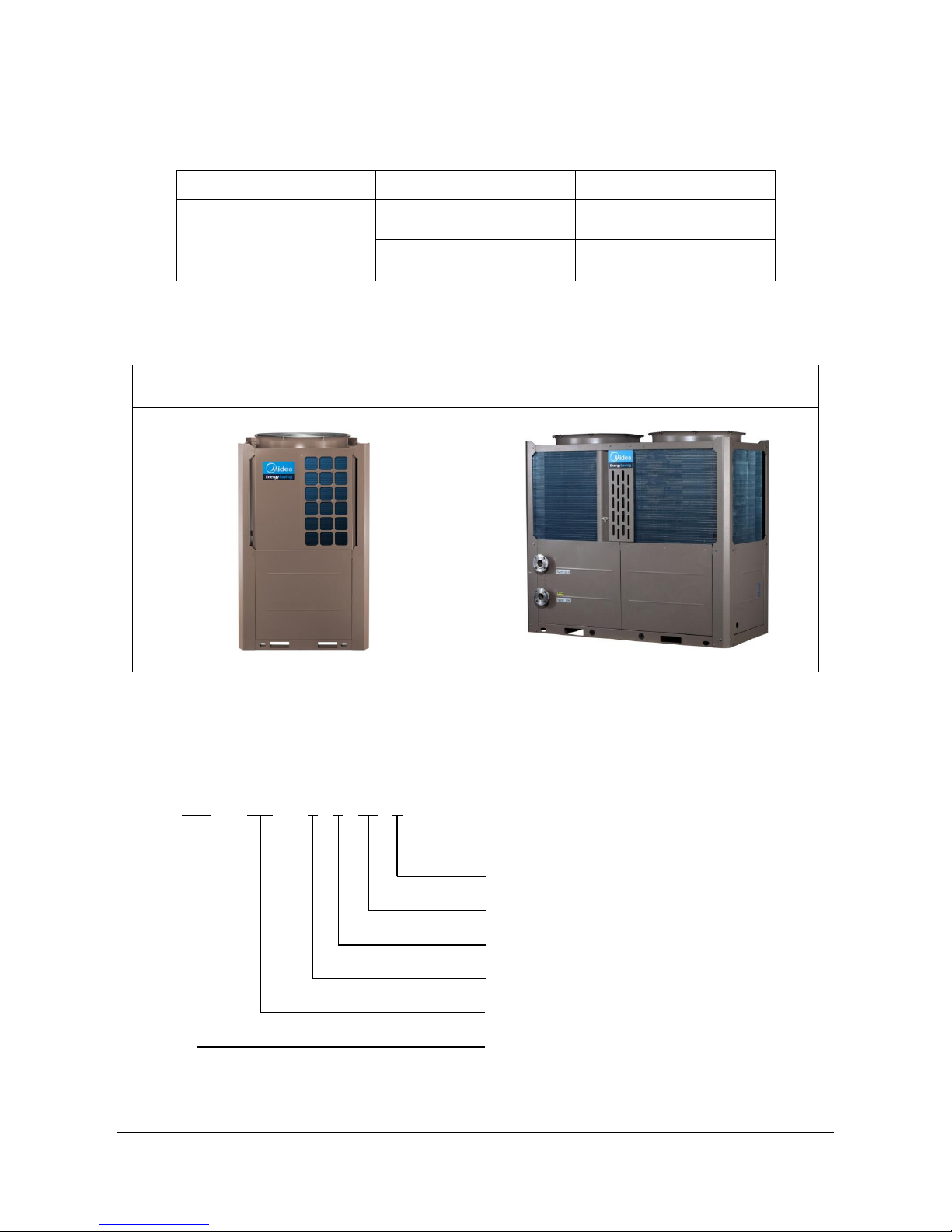
2. External Appearance
RSJ-420/PZN1-H
RSJ-800/PZN1-H
3. Nomenclature
RSJ - 420 / S Z N1 - H
H type
Refrigerant type - N1: R410A
Direct-heating type & Pressure water tank
Power supply: 380-415V 3Ph 50Hz
Nominal heating capacity (420×100W)
Midea heat pump water heater
Page 5

Midea R410A Direct Heating Commercial Heat Pump 50Hz Technical Manual MCAC-HTSM-201506
5
Part. 2 Performance
1. Features .............................................................................. 6
2. Specifications ...................................................................... 7
3. Dimensions (Unit: mm) ........................................................ 9
4. Service Space (Unit: mm) .................................................. 11
5. Refrigerant circuit .............................................................. 13
6. Wiring Diagrams ................................................................ 15
7. Electric Characteristics ...................................................... 22
8. Capacity Table ................................................................... 23
9. Accessories ....................................................................... 25
Page 6

MCAC-HTSM-201506 Midea R410A Direct Heating Commercial Heat Pump 50Hz Technical Manual
6
1. Features
High capacity of hot water producing,
High efficient, COP is up to 4.04 (39kW) and 4.00 (80kW).
Unit applies refrigerant heating technology to increase the total energy absorb.
Refrigerant E-heater design can ensure that hot water can be produced stably during defrosting
period.
Multi protection: High and low pressure protection, over-load current protection, anti-freezing
function, etc.
Multi-temperature sensors always monitor the unit operating status.
Max. 4 units can be connected in parallel (39kW); Max. 2 units can be connected in parallel
(80kW).
User-friendly wired controller as standard, real-time clock function, power-off memory function.
Page 7
Midea R410A Direct Heating Commercial Heat Pump 50Hz Technical Manual MCAC-HTSM-201506
7
2. Specifications
Model
RSJ-420/SZN1-H
Power supply \ 380-415V~, 3Ph, 50Hz
Water heating
Capacity
kW
39.0
Input
kW
9.65
COP
W/W
4.04
Running ambient temperature
\
-15 ºC ~46 ºC
Outlet water temperature
\
Default 56ºC, 40 ºC~60 ºC
Rated input
kW
14.5
Rated current
A
24.0
Noise level
dB(A)
66
Refrigerant type
\
R410A
Quantity
\
4.5kg
Refrigerant control
\
EXV
Fan
Type
\
Axial fan
Motor model
\
YDK550-6E
Motor brand \ Yongan/Dayang/Welling/Matchwell
Quantity
\ 1 Motor input
W
810/680
Capacitor
25μF/450V
Speed (Hi/lo)
r/min
850/750
Coil
Type
\
Copper tube and aluminum fin
Tube size
mm
Ф7
No. of rows
\ 2 Fin spacing
mm
1.5
Tube pitch(a)×row pitch(b)
mm
21×13.37
Length× height
mm
2,827×798
Number of circuits
\
19
Compressor
Model
\
ZP120KCE-TFD-522
Type
\
Scroll
Brand
\
Copeland
Quantity
\ 1 Capacity
kW
29.2
Input
W
9,200
Rated current (RLA) A 20
Locked rotor Amp.(LRA) A 118
Thermal protector \ Internal
Refrigerant oil
ml
3,253
Controller \ KJR-51/BMKE-A (Wired controller)
Air flow
m3/h
≥12,000
Page 8
MCAC-HTSM-201506 Midea R410A Direct Heating Commercial Heat Pump 50Hz Technical Manual
8
Continues
Model
RSJ-420/SZN1-H
Water pipe
Inlet pipe
mm
DN32
Outlet pipe
mm
DN32
Hot water yield
m3/h
0.85
Dimension (W×H×D)
mm
1,015×1,775×1,026
Packing (W×H×D)
mm
1,070×1,900×1,030
Net/Gross weight
kg
323/343
Notes:
The heating capacity is tested under a standard ambient with temperature of outdoor 20 ºC (DB)/15 ºC (WB),
inlet water temperature of the unit is 15 ºC , outlet water temperature is 55 ºC .
Model
RSJ-800/SZN1-H
Power supply \ 380-415V~, 3Ph, 50Hz
Water
heating
Capacity
kW
80.0
Input
kW
20.00
COP
W/W
4.00
Running ambient temperature
\
-15 ºC ~46 ºC
Outlet water temperature
\
Default 56ºC, 40 ºC~60 ºC
Rated input
kW
26.0
Rated current
A
34.0
Noise level
dB(A)
68
Refrigerant type
\
R410A
Quantity
\
4.4kg×2
Refrigerant control
\
EXV
Fan
Type
\
Axial fan
Motor model
\
YDK550-6E
Motor brand \ Yongan/Dayang/Welling/Matchwell
Quantity
\
2
Motor input
W
810/680
Capacitor
25μF/450V
Speed (Hi/lo)
r/min
850/750
Coil
Type
\
Copper tube and aluminum fin
Tube size
mm
Ф7
No. of rows
\ 2 Fin spacing
mm
1.5
Tube pitch(a)×row pitch(b)
mm
21×13.37
Length× height
mm
(2,827×798)+(2,827×798)
Number of circuits
\
20+20
Page 9
Midea R410A Direct Heating Commercial Heat Pump 50Hz Technical Manual MCAC-HTSM-201506
9
Continues
Model
RSJ-800/SZN1-H
Compressor
Model
\
SH120A4ALC
Type
\
Scroll
Brand
\
Danfoss
Quantity
\ 2 Capacity
kW
29.95
Input
W
9,462
Rated current (RLA) A 20.7
Locked rotor Amp.(LRA) A 142
Thermal protector \ Internal
Refrigerant oil
ml
3,300
Controller \ KJR-51/BMKE-A (Wired controller)
Air flow
m3/h
≥25,000
Water pipe
Inlet pipe
mm
DN50
Outlet pipe
mm
DN50
Hot water yield
m3/h
1.72
Dimension (W×H×D)
mm
1,015×1,775×1,026
Packing (W×H×D)
mm
1,070×1,900×1,030
Net/Gross weight
kg
599/627
Notes:
The heating capacity is tested under a standard ambient with temperature of outdoor 20 ºC (DB)/15 ºC (WB),
inlet water temperature of the unit is 15 ºC , outlet water temperature is 55 ºC .
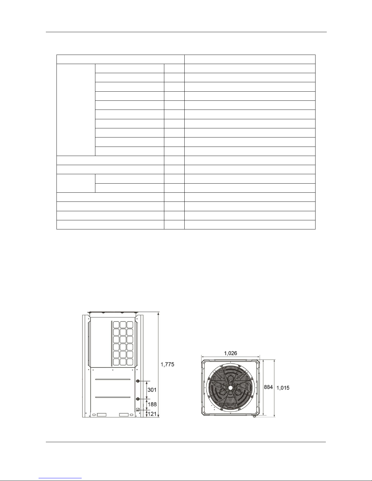
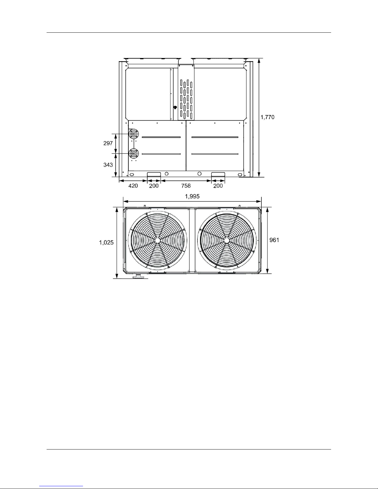
3. Dimensions (Unit: mm)
RSJ-420/SZN1-H
Top view
Page 10
MCAC-HTSM-201506 Midea R410A Direct Heating Commercial Heat Pump 50Hz Technical Manual
10
RSJ-800/SZN1-H
Top view
Page 11
Midea R410A Direct Heating Commercial Heat Pump 50Hz Technical Manual MCAC-HTSM-201506
11
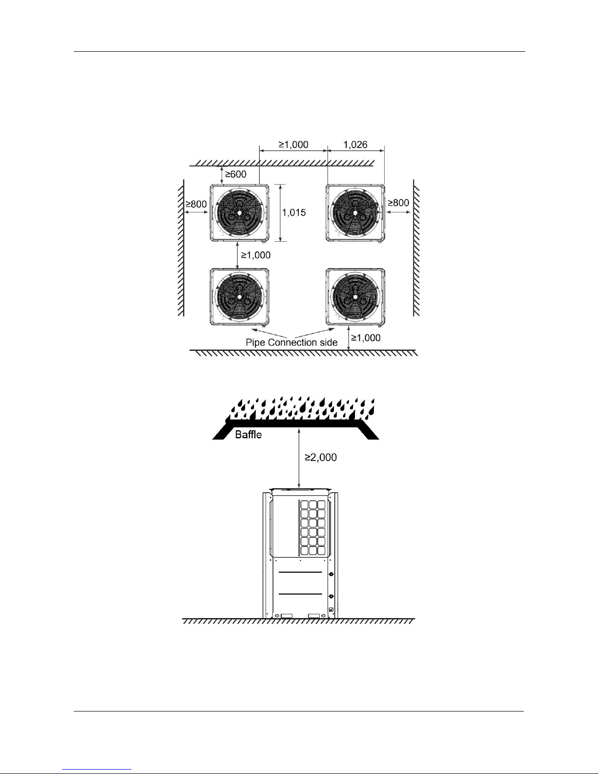
4. Service Space (Unit: mm)
RSJ-420/SZN1-H
Page 12
MCAC-HTSM-201506 Midea R410A Direct Heating Commercial Heat Pump 50Hz Technical Manual
12
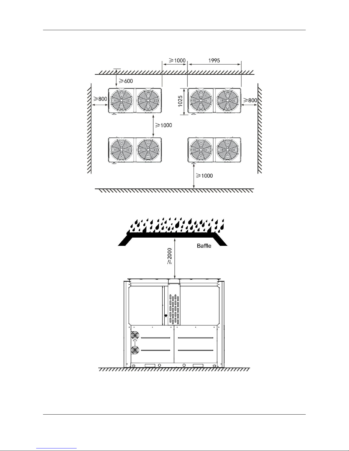
RSJ-800/SZN1-H
Page 13
Midea R410A Direct Heating Commercial Heat Pump 50Hz Technical Manual MCAC-HTSM-201506
13
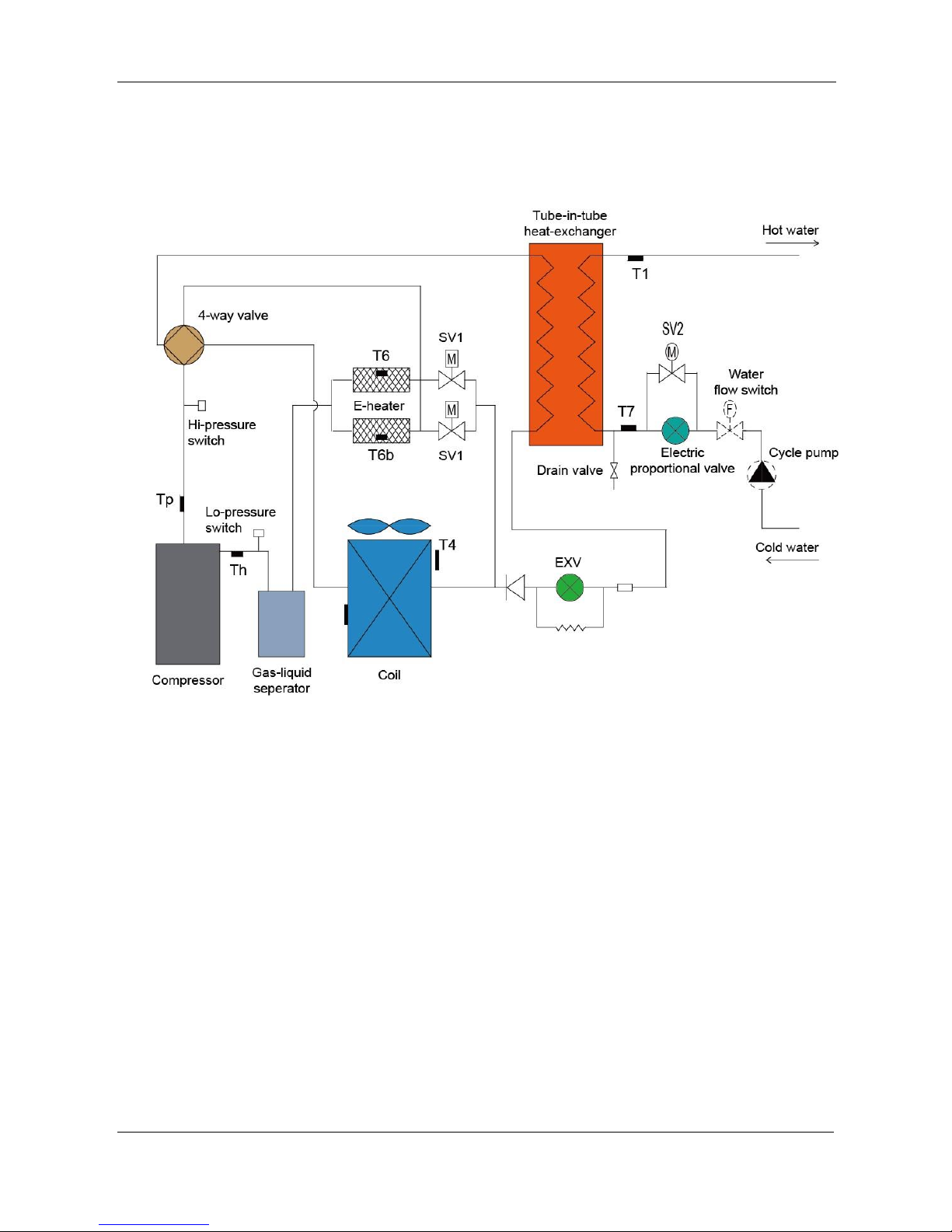
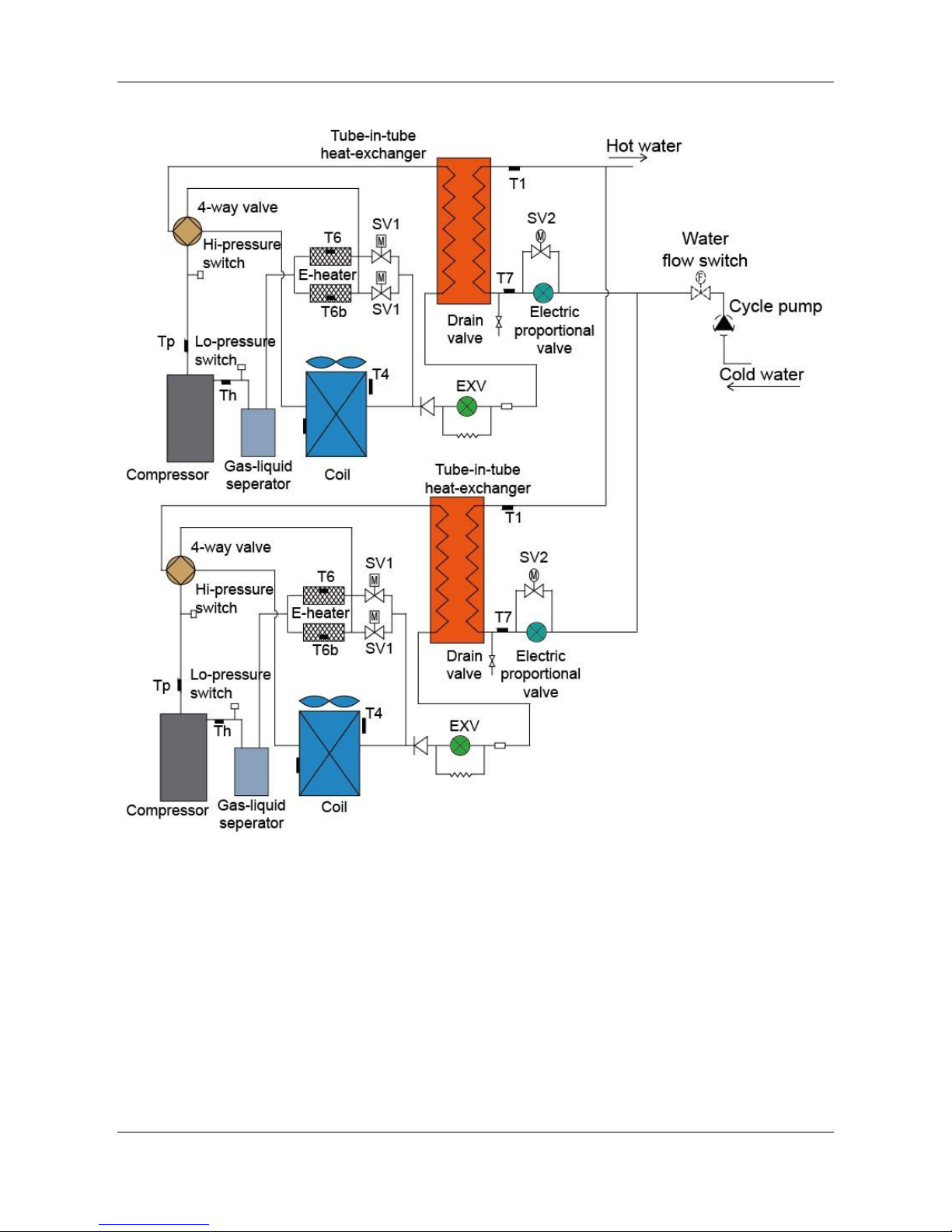
5. Refrigerant circuit
RSJ-420/SZN1-H
Page 14
MCAC-HTSM-201506 Midea R410A Direct Heating Commercial Heat Pump 50Hz Technical Manual
14
RSJ-800/SZN1-H
Page 15
Midea R410A Direct Heating Commercial Heat Pump 50Hz Technical Manual MCAC-HTSM-201506
15
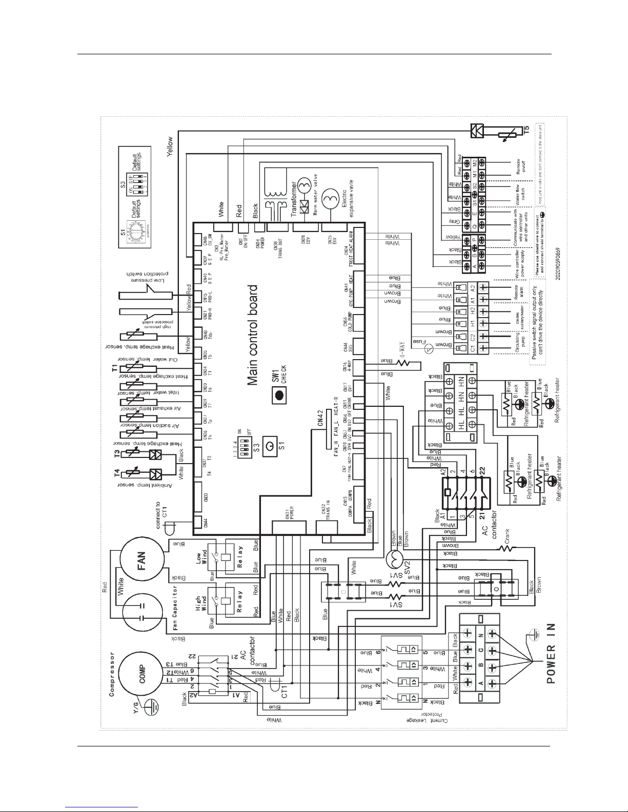
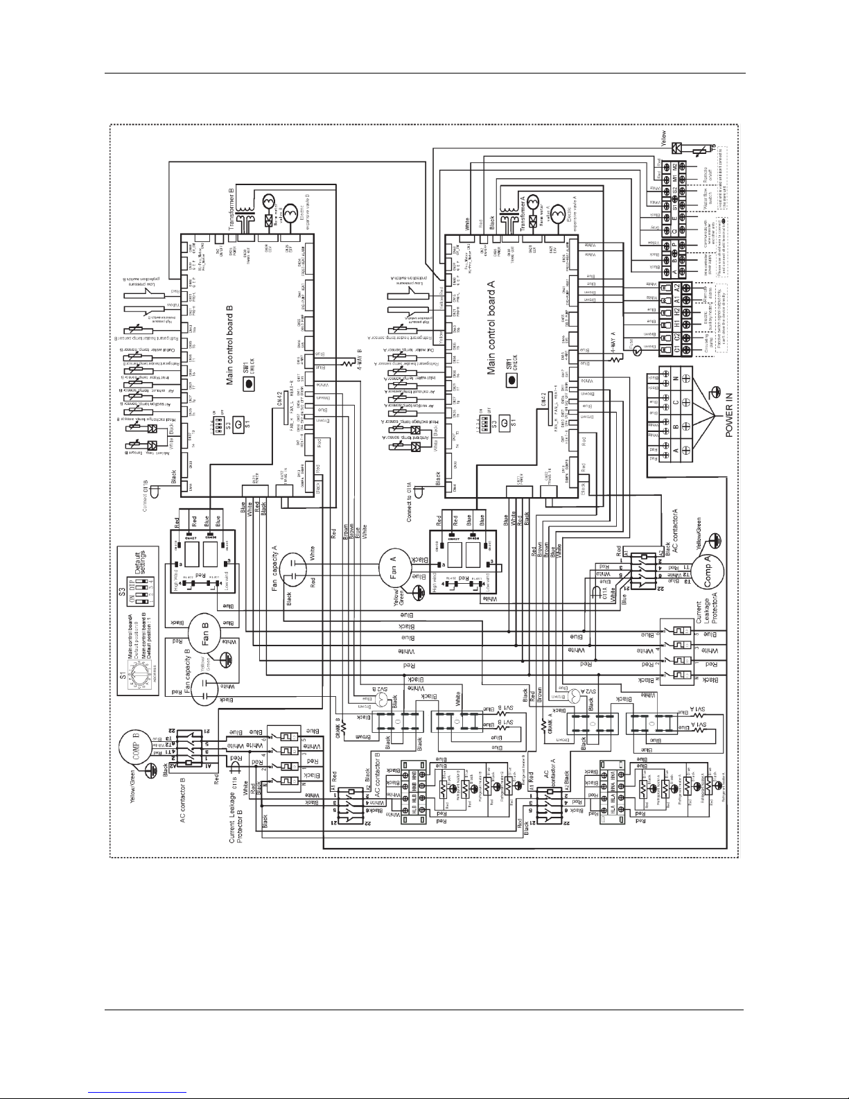
6. Wiring Diagrams
RSJ-420/SZN1-H
Page 16
MCAC-HTSM-201506 Midea R410A Direct Heating Commercial Heat Pump 50Hz Technical Manual
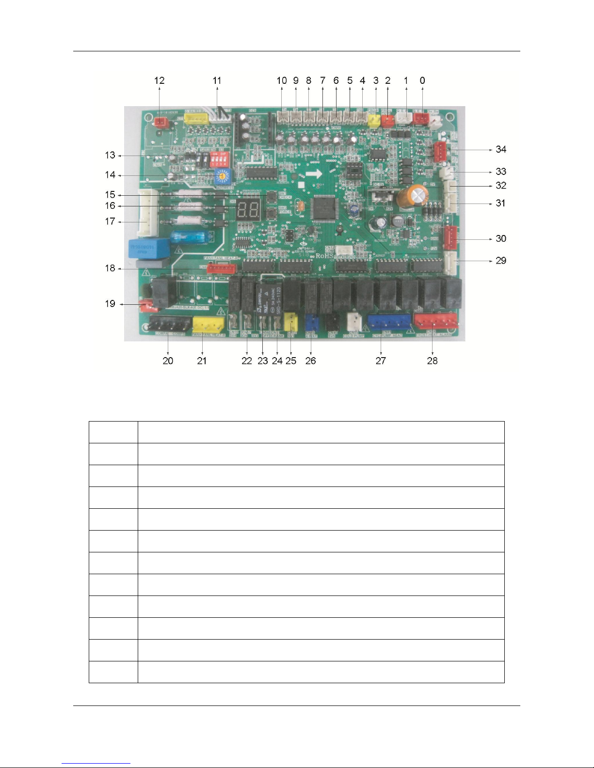
16
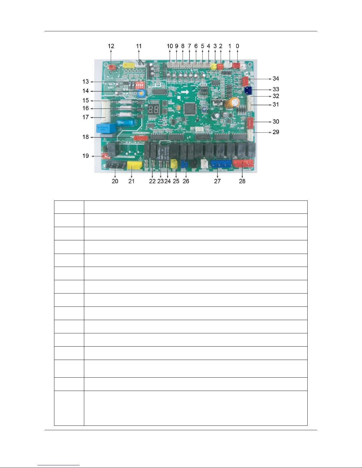
Item
Detail
0
Communication port for other unit
1
Communication port for wired controller
2
System low pressure protection connector
3
System high pressure protection connector
4
E-heater Temp. Sensor of refrigerant connector
5
Water tank (pook) Temp. sensor connector, only the host is valid, the slave is invalid
6
Water outlet Temp. sensor connector
7
E-heater pipe Temp. sensor connector of refrigerant
8
Water inlet Temp. sensor connector
9
Discharge Temp. sensor connector
10
Suction sensor connector
Page 17
Midea R410A Direct Heating Commercial Heat Pump 50Hz Technical Manual MCAC-HTSM-201506
17
11
T3: Evaporator Temp. sensor connector
T4: Outdoor ambient Temp. sensor connector
12
Detection port for compressor current
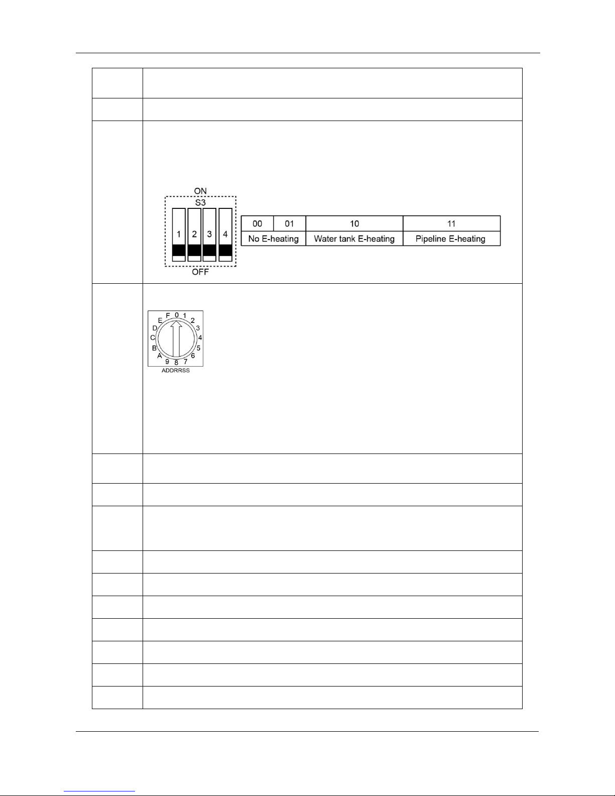
13
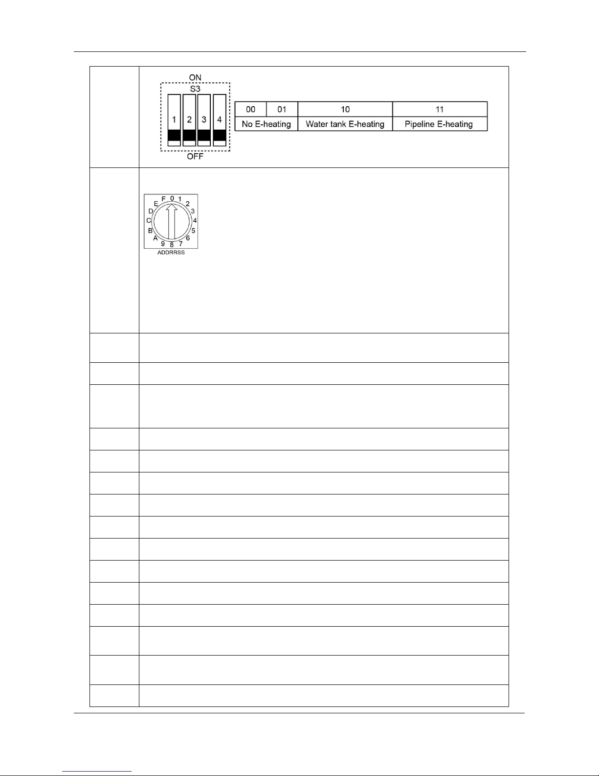
S3-1: Remote ON/OFF functional status (OFF: inactive (default); ON: active)
S3-2: Defrost periodical choice (OFF: default time by program; ON: 28 minutes)
S3-3,4: Auxiliary heater choice (OFF: indicates 0, ON indicates 1, the factory default
is 00)
14
Address dial code
0~3 separately stands for address 0~3, means 0~3 set units. When
dial the dial switch to 4 or more, then it will invalid.
Each module of water heat pump has the electric control function. Set the host unit
through the address dial code on electric control board. Stipulate the unit with
address dial code 0# as the host unit. Only after setting the host unit , the function of
direct communication with wired controller and other function can be activated.
15
Left side: CHECK, spot check button, for checking the operating state of unit.
Right side: FORCE, constraint button, special function for constraint exit.
16
Digital screen.
17
3-phase, 4-wire system power input. Lack of phase or wrong phase only is detected
on the initial stage of power on without detection during operation.
18
High and low fan speed.
19
Tranformer input, 220V AC current.
20
Control port for compressor.
21
Refrigerant E-heater control port.
22
Electric ball valve on.
23
Electric ball valve off.
24
Control port for crankcase E-heating belt.
Page 18
MCAC-HTSM-201506 Midea R410A Direct Heating Commercial Heat Pump 50Hz Technical Manual
18
25
One-way solenoid control port.
26
4-way valve control power.
27
Left side: Circulating water pump control; right side: E-heater control. Only supply
ON/OFF signal, not supply power signal.
28
Right side: Remote alarm signal output. Only supply non-source ON/OFF signal, not
supply power signal.
29
EXV connector.
30
Electric proportional valve connector.
31
Transformer output connector.
32
Power connector for wired controller.
33
Remote control port.
34
Water flow switch connector.
Page 19
Midea R410A Direct Heating Commercial Heat Pump 50Hz Technical Manual MCAC-HTSM-201506
19
RSJ-800/SZN1-H
Page 20
MCAC-HTSM-201506 Midea R410A Direct Heating Commercial Heat Pump 50Hz Technical Manual
20
Item
Detail
0
Communication port for other unit
1
Communication port for wired controller
2
System low pressure protection connector
3
System high pressure protection connector
4
E-heater Temp. Sensor of refrigerant connector
5
Water tank (pook) Temp. sensor connector, only the host is valid, the slave is invalid.
6
Water outlet Temp. sensor connector
7
E-heater pipe Temp. sensor connector of refrigerant
8
Water inlet Temp. sensor connector
9
Discharge Temp. sensor connector
10
Suction sensor connector
11
T3: Evaporator Temp. sensor connector
T4: Outdoor ambient Temp. sensor connector
12
Detection port for compressor current
13
S3-1: Remote ON/OFF functional status (OFF: inactive (default); ON: active)
S3-2: Defrost periodical choice (OFF: default time by program; ON: 28 minutes)
S3-3,4: Auxiliary heater choice (OFF: indicates 0, ON indicates 1, the factory default
is 00)
Page 21
Midea R410A Direct Heating Commercial Heat Pump 50Hz Technical Manual MCAC-HTSM-201506
21
14
Address dial code
0~1 separately stands for address 0~1, means 0~1 set units. When
dial the dial switch to 2 or more, then it will invalid.
Each module of water heat pump has the electric control function. Set the host unit
through the address dial code on electric control board. Stipulate the unit with
address dial code 0# as the host unit. Only after setting the host unit , the function of
direct communication with wired controller and other function can be activated.
15
Left side: CHECK, spot check button, for checking the operating state of unit.
Right side: FORCE, constraint button, special function for constraint exit.
16
Digital screen.
17
3-phase, 4-wire system power input. Lack of phase or wrong phase only is detected
on the initial stage of power on without detection during operation.
18
High and low fan speed.
19
Tranformer input, 220V AC current.
20
Control port for compressor.
21
Refrigerant E-heater control port.
22
Electric ball valve on.
23
Electric ball valve off.
24
Control port for crankcase E-heating belt.
25
One-way solenoid control port.
26
4-way valve control power.
27
Left side: Circulating water pump control; right side: E-heater control. Only supply
ON/OFF signal, not supply power signal.
28
Right side: Remote alarm signal output. Only supply non-source ON/OFF signal, not
supply power signal.
29
EXV connector.
Page 22
MCAC-HTSM-201506 Midea R410A Direct Heating Commercial Heat Pump 50Hz Technical Manual
22
30
Electric proportional valve connector.
31
Transformer output connector.
32
Power connector for wired controller.
33
Remote control port.
34
Water flow switch connector.
Notes: RSJ-800/SZN1-H has two same PCB boards. Here only explains one PCB board.
7. Electric Characteristics
Model
RSJ-420/SZN1-H
RSJ-800/SZN1-H
Outdoor unit
Hz
50
50
Voltage
380~415V, 3Ph
380~415V, 3Ph
Min.
342V
342V
Max.
456V
456V
Power supply
MCA
21
26
TOCA
30
60
MFA
30
60
Compressor
MSC
118
142
RLA
16.6
20.7
OFM
kW
0.8
0.8
FLA
3.7
3.7
Note:
MCA: Min. Current Amps. (A) MFA: Max. Fuse Amps. (A)
TOCA: Total Over-current Amps. (A) MSC: Max. Starting Amps. (A)
RLA: Rated Locked Amps. (A) OFM: Outdoor Fan Motor
kW: Fan Motor Rated Output (kW) FLA: Full Load Amps. (A)
Page 23
Midea R410A Direct Heating Commercial Heat Pump 50Hz Technical Manual MCAC-HTSM-201506
23
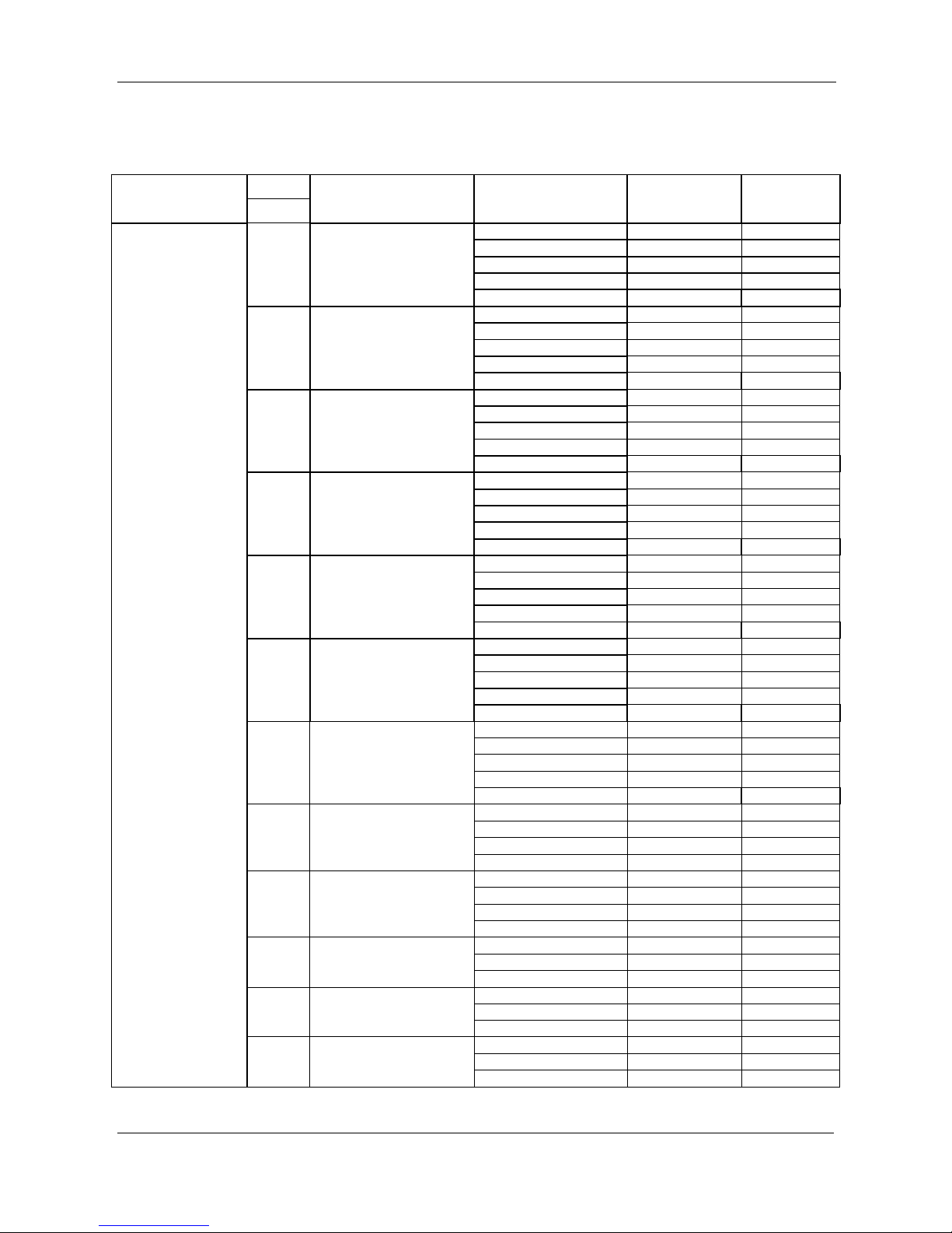
8. Capacity Table
RSJ-420/SZN1-H
Mode
OT(℃)
Inlet water Temp. (℃)
Outlet water Temp.
(℃)
Capacity(kW)
COP
DB
RSJ-420/SZN1-H
43
29
60
52.46
5.03
40
29
45
55.14
5.89
60
52.67
5.19
35
29
45
51.13
5.36
30
15
45
46.31
5.32
25
15
45
42.62
4.86
55
44.28
4.34
20
15
55
39.76
4.01
15
9
55
37.54
3.90
7
9
40
32.23
4.65
2
9
0
9
-7
9
-15
9
Page 24
MCAC-HTSM-201506 Midea R410A Direct Heating Commercial Heat Pump 50Hz Technical Manual
24
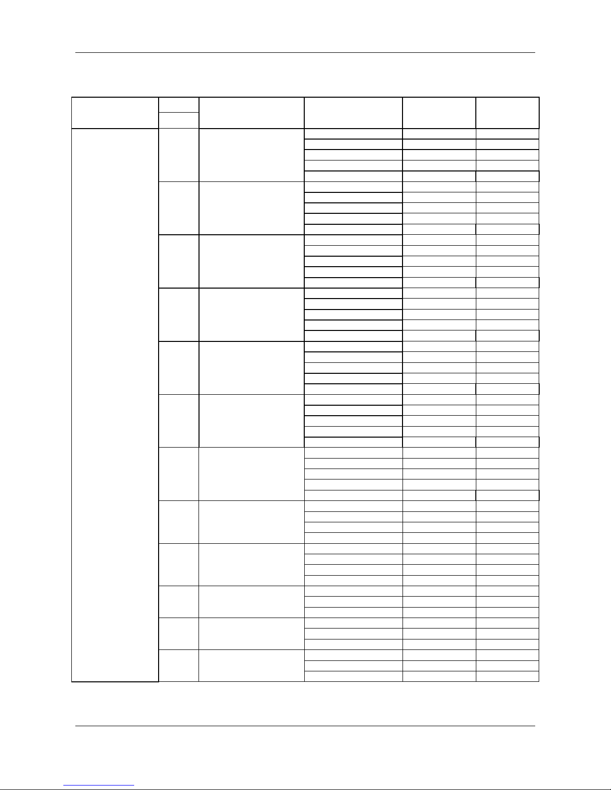
RSJ-800/SZN1-H
Note: OT – Outdoor Temperature (DB);
Mode
OT(℃)
Inlet water Temp. (℃)
Outlet water Temp.
(℃)
Capacity(kW)
COP
DB
RSJ-800/SZN1-H
43
29
60
99.08
4.44
40
29
60
97.95
4.35
35
29
45
94.75
5.06
30
15
45
88.62
5.00
25
15
45
83.64
4.64
55
83.70
4.15
20
15
55
81.05
4.04
15
9
55
75.04
3.84
7
9
40
65.25
4.04
2
9
0
9
-7
9
-15
9
Page 25

Midea R410A Direct Heating Commercial Heat Pump 50Hz Technical Manual MCAC-HTSM-201506
25
9. Accessories
Name
Qty.
Purpose
Installation & operation manual
1
Water tank temperature sensor
1
For water tank temperature inspection.
Wired controller
1
Control the unit and display unit status.
Wire harness matched with wired controller
1
Connect the master unit with wired controller.
Y-shaped filter
1
Only for RSJ-420/SZN1-H
Page 26

MCAC-HTSM-201506 Midea R410A Direct Heating Commercial Heat Pump 50Hz Technical Manual
26
Part. 3 Installation
1. Safety information ............................................................... 27
2. Unit Installation ................................................................... 28
3. Trial run ............................................................................... 44
4. Fault analysis and solutions ................................................ 46
5. Maintenance ....................................................................... 59
Page 27

Midea R410A Direct Heating Commercial Heat Pump 50Hz Technical Manual MCAC-HTSM-201506
27
1. Safety information
To prevent injury to the user or other people and property damage, the following instructions must be
followed. Incorrect operation due to ignoring of instructions may cause harm or damage.
The unit must be earthed effectively. The earthing pole of socket must be grounded well, make
sure that power supply socket and plug are dry enough and connected tightly.
How to check the power supply socket and plug are qualified? Turn on power supply and keep
the unit running for a half hour, then turn off power supply and plug out, check whether the
socket and plug is hot or not.
Do not remove, cover or deface any permanent instructions, labels, or the data labels from either
the outside of the unit or inside of unit panels.
Ask qualified person to perform the installation of this unit in accordance with local national
regulations and this manual. Improper installation may result in water leakage, electric shock or
fire.
Ask qualified person for relocating, repairing and maintaining the unit. Improper installation may
result in water leakage, electric shock or fire.
Electric connection work should obey the instructions of local power company, local electric
utility and this manual.
Never use the wire and fuse with wrong rated current, otherwise unit may break down and cause
fire furthermore.
Do not insert fingers, rods or other objects into the air inlet or outlet. When the fan is rotating at
high speed, it will cause injury.
Never use a flammable spray such as hair spray, lacquer paint near the unit. It may cause a fire.
This appliance is not intended for use by person (including children) with reduced physical,
sensory or mental capabilities, or lack of experience and knowledge, unless they have been
given supervision or instruction concerning use of the appliance by a person responsible for their
safety. Children should be supervised to ensure that they do not play with the appliance.
If the supply cord is damaged, it must be replaced by the manufacturer or its service agent or
Page 28

MCAC-HTSM-201506 Midea R410A Direct Heating Commercial Heat Pump 50Hz Technical Manual
28
similarly qualified person.
Do not dispose this product as unsorted municipal waste. Collection of such waste separately for
special treatment is necessary. Do not dispose of electrical appliances as unsorted municipal
waste, use separate collection facilities. Contact your local government for information regarding
the collection systems available. If electrical appliances are disposed of in landfills or dumps,
hazardous substances can leak into the ground water and get into the food chain, damaging
people’s health and well-being.
Before cleaning, be sure to stop the operation and turn the breaker off or pull out the power plug.
Otherwise, an electric shock and injury may be caused.
Water temperature over 50°C can cause severe burns instantly or death from scalds. Children,
disabled and elderly are at highest risk of being scalded. Feel water before bathing or showering
valves are recommended.
Do not operate the unit with a wet hand. An electric shock may be caused.
The installation height of power supply should be over 1.8m, if there is any water spattered,
separate the power supply from water.
A one-way valve must be installed on the water inlet side, which is available from accessories.
Arrange the drain pipe to ensure smooth draining. Improper drainage work may cause wetting of
the building, furniture, etc.
Do not touch the inner parts of the controller. Do not remove the front panel. Some parts inside
are dangerous to touch, otherwise a machine malfunction may be caused.
Do not turn off the power supply. System will stop or restart heating automatically. A continuous
power supply for water heating is necessary, except service and maintenance.
2. Unit Installation
Except for accessories supplied by factory, the water flow switch should be supplied by site. The
cut-off value of switch should be more than V (V=0.1m3/h × Amount of units). The water flow switch is
used to detect the circulating water flow volume.
A single unit must be installed a set of water flow switch and wired controller, several units parallel
connected can choose one or more sets of above accessories as required.
Page 29

Midea R410A Direct Heating Commercial Heat Pump 50Hz Technical Manual MCAC-HTSM-201506
29
2.1 Unit outlook
RSJ-420/SZN1-H
RSJ-800/SZN1-H
2.2 Carrying of unit
Handling rope should at least can bear 3 times of the unit weight, and must go through the
handling holes shown in following pictures, and make sure there is enough strength to add a
Page 30

MCAC-HTSM-201506 Midea R410A Direct Heating Commercial Heat Pump 50Hz Technical Manual
30
pad between the rop and unit in order to protect the unit.
Distance between the hood and air outlet mesh shoule be more than 1 meter, and ensure
that the hood has enough strength as well as reliability in handling process.
Unit gradient (α) should be less than 3º. Handle with care, do not collide and drag drastically.
DO NOT stand in handling operating radius.
The distance between the air outlet mesh of unit and lift hook should be more than 1 meter.
RSJ-420/SZN1-H
RSJ-800/SZN1-H
2.3 Unit installation caution
The unit can be installed on the ground or on the suitable roof, but enough ventilation
volume should be ensured in both cases.
The unit should not be installed where noise and vibration are required to a certain extent.
Page 31

Midea R410A Direct Heating Commercial Heat Pump 50Hz Technical Manual MCAC-HTSM-201506
31
The installed unit should be sheltered from direct sunlight as much as possible, and be far
away from boiler flues and ambient air which may erode condenser coils and copper tube
parts of the unit, such as the places that full of dust and oil fume.
Safety measures of isolation should be taken, such as rail guards. These measures will
avoid artificial damages and accidental damages.
The height of the installation foundation for the unit should not be less than 100mm, and
floor drains are required in installation sites, to ensure smooth drainage and remove any
seeper.
In case of installation on the ground, the steel base of the unit should be located on the
concrete foundation, and the concrete plinth should extend below frozen soil layer. The
foundation of the unit should not be connected to the foundation of the building, to avoid
affecting the people due to transfer of noise and vibration. The base of the unit is provided
with installation holes, which can be used to connect the unit and the foundation firmly.
In case of installation on the roof, the roof must possess enough strength to sustain weight
of the unit and maintenance personnel. The unit can be supported on concrete foundations
or channel steel frames similar to those used in the unit installation on the ground. The
load-bearing channel steel must be in alignment with the installation holes of the unit
damper, and the channel steel should posses enough width for installing the damper.
Consult the building contractor, the archietectural designer or other specialists about the
cased with special installation requirements.
The unit can be installed on the ground or ont the suitable roof, but it should follows the
relative standards or laws to all lightnin-proof measures for the whole water heating system.
2.4 distance of unit ground screws (Unit: mm)
RSJ-420/SZN1-H
Page 32

MCAC-HTSM-201506 Midea R410A Direct Heating Commercial Heat Pump 50Hz Technical Manual
32
RSJ-800/SZN1-H
2.5 Unit installation space
Ensure enough space for installation and maintenance.
RSJ-420/SZN1-H
(Unit: mm)
RSJ-800/SZN1-H
(Unit: mm)
Page 33

Midea R410A Direct Heating Commercial Heat Pump 50Hz Technical Manual MCAC-HTSM-201506
33
Ensure there is enough air flow to supply the heat exchanger, Take influence of down draft
caused by tall building around the unit to air discharge into condenser when installing.
If install the unit at a place where ventilation is drastic, such as exposed roofs, short wall or
louvers can be applied in case of turbulence disturbs air inlet. If short walls are applied, it
should be shorter than the unit. Distance between short walls or louvers to unit should either
satisfy requirements of unit installation minimum intervals.
If the unit runs in winter, and the location has accumulated snow, the unit should stand
higher than snow in order to let airflow ge through heat exchanger fluently.
The unit circulating air volume is at least 12,000m3/h. If the unit is installed in the basement,
ensure air around the unit and outdoor air can circulate without obstruction.
RSJ-420/SZN1-H
(Unit: mm)
RSJ-800/SZN1-H
(Unit: mm)
Page 34

MCAC-HTSM-201506 Midea R410A Direct Heating Commercial Heat Pump 50Hz Technical Manual
34
2.6 Water pipeline system
Water pipe joint specifications of single unit.
Water inlet pipe joint
Water outlet pipe joint
RSJ-420/SZN1-H
DN32
DN32
RSJ-800/SZN1-H
DN50
DN50
Water pipeline system design and construction must meet the national water and heating
pipeline design requirements and relative standards.
All the pipes are recommended to use PPR pipe, and the PPR pipe specificatons refers to
up table.
It must prevent dust and other sundries enter into the pipeline system during the pipeline
installation and connection.
The water flow switch which is used to detect the circulating water flow volume should be
prepaired in site. The cut-off value of water flow switch is not less than (0.1m3/h×amount of
units).
Only after unit is fixed, the water pipes can be installed.
Use thermal insulation material to wrap the inlet water pipe, outlet water pipe and circulative
water pipes.
The pipe diameter of main water pipes:
RSJ-420/SZN1-H
Amount of units connected in parallel
Water inlet pipe joint
Water outlet pipe joint
1
DN32
DN32
2
DN50
DN50
3
DN65
DN65
4
DN80
DN80
RSJ-800/SZN1-H
Amount of units connected in parallel
Water inlet pipe joint
Water outlet pipe joint
1
DN50
DN50
2
DN80
DN80
Page 35

Midea R410A Direct Heating Commercial Heat Pump 50Hz Technical Manual MCAC-HTSM-201506
35
Connection diagrammatic drawing of water pipe system
Icon specifications:
Stop valve
Motor operated valve
Flexible rubber joint (soft-connect)
Water pump
Water using end
Water supply controller
Solenoid valve
Pressure reducing valve
Reflux valve
Auto air-exhaust valve
Pressure gage
E-heater
Y-shape filter
Water flow switch
RSJ-420/SZN1-H
Single unit drawing:
Page 36

MCAC-HTSM-201506 Midea R410A Direct Heating Commercial Heat Pump 50Hz Technical Manual
36
Double units drawing:
RSJ-800/SZN1-H
Single unit drawing:
Page 37

Midea R410A Direct Heating Commercial Heat Pump 50Hz Technical Manual MCAC-HTSM-201506
37
Double units drawing:
2.7 Water tank installation
The water tank temperature sensor (T5) can not be placed in the water or on the water pipe
directly. The water tank must be set a temperature pipe where the temperature sensor (T5)
is installed.
The water tank must have some safty devices to protect it such as temperature cut off
switch, pressure and temperature relief vale, etc.
Make sure E-heater is covered with water all the time.
Page 38

MCAC-HTSM-201506 Midea R410A Direct Heating Commercial Heat Pump 50Hz Technical Manual
38
Water cycle pump selection:
RSJ-420/SZN1-H
Circulative heating rated water flow
7 m3/h
Water resistance of circulative rated water flow
160 kPa
RSJ-800/SZN1-H
Circulative heating rated water flow
14 m3/h
Water resistance of circulative rated water flow
160 kPa
The hot water circulative pump must use hot water pump; the temperature resistance of the
circulative water pump cannot lower than 80°C.
Rated head of circulative pump:
ΣOn-way resistance + ΣLocal resistance + Unit resistance
Rated flow of circulative pump:
Rated flow of a single circulation heating unit × Circulating unit quantity
2.8 E-heater capacity selection
As the requirement, the auxiliary electric heater can be selected. The host unit provides the
passive control signals of the auxiliary heater.
The installation location of the auxiliary heater must strictly comply with the installation
schematatic diagram.
Rated heating capacity of total unit × 10%~30%.
E-heater can apply the pipe-type or water tank E-heater. After installation, it must through
dialing codes to choose the relative E-heating mode, otherwise it will damage the unit or
Page 39

Midea R410A Direct Heating Commercial Heat Pump 50Hz Technical Manual MCAC-HTSM-201506
39
E-heater.
The selection of auxiliary heater is only for reconmendation, and the selection of auxiliary
heater can be selected according to the actual conditions.
Make sure E-heater is covered with water all the time.
2.9 Electric connection of the unit
Only use the electric components specified by product manufacture.
Electronic installation must comply with the native regulations. Independent power supply
should be applied. Power supply should satisfy electrical specifications that the unit
requires.
The unit must be ground wiring reliably.
Set leakage protective devices according to the requirements of national technical standard
about electric equipment.
Power supply wire and signal wire should be arranged properly without interruption to each
other, do not contact with connecting pipes and valves as well.
When strong electricity and weak electricity are in parallel, please put the cable into each
other’s circuit and leave a proper space.
No power supply wire is provided, please refer to the requirements in national standards or
factory.
In following table, power supply wire and connection length is the situation when voltage
drop range is within 2%, if wire continuous length exceeds the ones listed in the table,
please choose wires with a right diameters according to relative regulation.
When finishing wiring, power on when there is no mistakes after a careful inspections.
RSJ-420/SZN1-H
Power supply
380-415V, 3Ph, 50Hz
Min. wire size
(metal pipe & synthetic resin pipe wire)
Wire size (˂30m)
10# (UL1015)
Ground wire
10# (UL1015)
Manual switch
Capacity
63 A
Fuse
50 A
Leakage protector
30mA 0.1sec below
Page 40

MCAC-HTSM-201506 Midea R410A Direct Heating Commercial Heat Pump 50Hz Technical Manual
40
RSJ-800/SZN1-H
Power supply
380-415V, 3Ph, 50Hz
Min. wire size
(metal pipe & synthetic resin pipe wire)
Wire size (˂30m)
25mm2
Ground wire
25mm2
Manual switch
Capacity
125A
Fuse
100A
Leakage protector
30mA 0.1sec below
Specifications of controlling wire
Item
Size (UL1015)
Remarks
E-heater controlling wire
18#
2-core
Circulating water pump controlling wire
18#
2-core
Remote alarm control wire
18#
2-core
Communication cable (shield)
22#
3-core
Wired controller power supply wire
22#
2-core
Targe flow switch
22#
2-core
Wiring diagram of water heater power
Single unit:
Page 41

Midea R410A Direct Heating Commercial Heat Pump 50Hz Technical Manual MCAC-HTSM-201506
41
Multi-units:
RSJ-420/SZN1-H
RSJ-800/SZN1-H
Page 42

MCAC-HTSM-201506 Midea R410A Direct Heating Commercial Heat Pump 50Hz Technical Manual
42
Electric wiring figure
Electric control schematic diagram of the unit (Only for reference)
Page 43

Midea R410A Direct Heating Commercial Heat Pump 50Hz Technical Manual MCAC-HTSM-201506
43
When power supply wire of the wired controller is less than 20m, wiring can be applied as
the location shown as imaginary lines, when it it exeeds 20m, the power adapter is
necessery.
Pay attention to the power phase sequence, if wrong connection of the phase sequence,
the compressor will not operate, and digital screen of the water heater electrical control
board will display error code. Change the phase sequence, and powering again until the
digital screen does not display error and compressor starts normally.
The water flow switch, water pump, ON/OFF singal and E-heater are only connected with
the host unit, which are not 220V control signal. So do not directly drive loading.
When the host unit has any one error of E1, E2 or E8, all the water heaters stop operation.
When the main unit has E4 error, the host unit and wired controller alarm the error, the slave
units do not display error, then all the unit can not normally heat water, and go into backup
mode.
When the host unit has other errors (except E1, E2, E8), then only stop the host unit, other
units will not be affected. When the slave unit has error, only stop the operation of the error
unit, other units will not be affected.
When the main or slave unit has protecton, only stop that unit, other units will not be
affected.
Page 44

MCAC-HTSM-201506 Midea R410A Direct Heating Commercial Heat Pump 50Hz Technical Manual
44
Dial code specification
S3-1: Remote ON/OFF functional status (OFF: inactive (default); ON: active).
S3-2: Defrost periodical choice (OFF: default time by program; ON: 28 minutes).
S3-3,4: Auxiliary heater choice (OFF: indicates 0, ON indicates 1, the factory default is 00).
Address dial code
0~3 separately stands for address 0~3, means 0~3 set units. When dial the
dial switch to 4 or more for the unit RSJ-420/SZN1-H, and when dial the dial switch to 2 or
more for the unit RSJ-800/SZN1-H, then it will invalid.
Each module of water heat pump has the electric control function. Set the host unit through
the address dial code on electric control board. Stipulate the unit with address dial code 0#
as the host unit. Only after setting the host unit , the function of direct communication with
wired controller and other function can be activated.
3. Trial run
When use the wired controller to operate the water heater, please check as the following list:
No.
Item
Remark
1
Whether the unit is installed firmly.
2
Whether the air inlet and outlet of the unit has obstacle.
3
Whether the dial codes of each unit has dial to the correct position.
4
Whether check the leakage of the water system.
5
Whether the water system is clean.
Page 45

Midea R410A Direct Heating Commercial Heat Pump 50Hz Technical Manual MCAC-HTSM-201506
45
6
Whether the filter is clean.
7
Whether the water drain is smoothly.
8
Whether complete the heat insulation of the water pipe.
9
Whether vacuum the pipeline of water side.
10
Whether all the valves in the water side pipeline are under correct status.
11
Whether the water flow switch work well.
12
Whether the grounding correctly.
13
Whether the power voltage meets the requirements of the unit.
14
Whether the leakage protector can work effectively.
When use the wired controller to operate the water heater, please check as the following listed:
No.
Item
Remark
1
Whether all the buttons of wired controller are normal.
2 Whether the input voltage of the unit meet the requirements of the unit.
3 Whether the electronic lock has been unlocked.
4 Whether the water outlet temperature is normal.
5 Whether there is any abnormal vibration and noise during operation.
Notes:
The unit also has one function; it can easily to make the unit enter other modes.
Enter ‘Debugging replenishing’ method: Long press ‘CHECK’ button for 3~20s within 1 minute after
power on, then the digital screen will display ‘0’ and be flashed with 2Hz frequency, means enter to
the function selection state. Short check, the digital screen will successively display each
corresponding number:
No. 4: Capacity testing mode I;
No. 5: Drain water mode;
No. 6: Force cycle pump operating;
No. 8: Force defrosting;
No.10: Capacity testing mode II.
After 5s, the digital pipe will flash with 1Hz frequency; means has already entered the debugging
replenishing function.
Page 46

MCAC-HTSM-201506 Midea R410A Direct Heating Commercial Heat Pump 50Hz Technical Manual
46
4. Fault analysis and solutions
Not distribute to malfunction
Phenomena
Cause
White aerosol or globule is given out.
Or make sound of ‘hiss’ every now
and then.
When the unit is defrosting, the sound of the 4-way valve
being shifted. Air supply motor stop automatically to defrost.
At the beginning and the end of the defrost process, sound
is given out in motor valve occur.
During the process or just after have stopped, sound likes
water flow occurs, which will be amplified at the first 2~3
minutes, this is caused by process of refrigerant current or
water discharge at dehumidifying operation.
Slight ‘hiss’ is caused by heat exchanger as temperature
changes. The sound gives out, because of heat expands
and cold contracts of heat exchanger.
During the beginning or just after have stopped, sound likes
clock occur, which is caused by electric expanding valve
operation.
Water outlet temperature fluctuation.
Because of different water inlet pressure, under special
working condition that may show up water outlet
temperature fluctuation, which is a normal phenomenon,
and will not affect the actual use; appropriately adjust the
water pressure can improve this phenomenon.
Water outlet temperature cannot reach
the setting temperature.
Under low temperature condition, for the purpose of
protecting the unit, the water outlet temperature may not
reach the higher setting temperature, which is a normal
phenomenon.
The terminal circulating water
temperature lower than the setting
temperature
For purpose of protecting the unit, the terminal circulating
water temperature cannot reach 60ºC, which is a
phenomenon, and will not affect the actual use.
Re-start after the unit stop, after 3
minutes then can be operated.
Compressor delay protection. It is a normal phenomenon.
The fan operates low speed or only
operates one fan.
When the ambient temperature is high, for protecting the
unit then the fan will shift to low speed or only operate one
fan.
Heat exchanger defrosting.
If operated in winter, for the heat exchanger surface
temperature is lower than the ambient one, and the heat
exchanger surface temperature is lower than 0ºC, the
surface will be frosted, which will affect the heat exchanging
effect, so the unit should be periodically defrosting.
The fan cannot operate.
During defrosting, the fan will not be operated.
Page 47

Midea R410A Direct Heating Commercial Heat Pump 50Hz Technical Manual MCAC-HTSM-201506
47
Need to check again
Phenomena
Cause
Stop operation or drive up
automatically
Detect the timer whether be given wrong operation.
Detect anti-freezing mode is opened.
No operation
Whether the power is cut.
Whether the manual power supply switch is off.
Whether the fuse is broken.
Whether the protection device works. (Operation lamp is
lightened.)
Whether it is the time set. (Operation lamp is lightened.)
Compressor is unable to drive
Possible reason
Detect and settle measure
1. Power errors.
Connected with wrong phase sequence.
2. Wire connection is loosening.
Check and fasten again.
3. Relay or fuse errors.
Check and repair.
4. Compressor errors.
Change the compressor.
Fan has loud noise
Possible reason
Detect and settle measure
1. Fixing screw of the fan is loosening.
Re-fasten the fixing screw of the fan.
2. Fan blade touched the cover shell
or screen
Check and adjust.
3. The fan operated unsteadily.
Change the fan.
Abnormal noise given out from compressor
Possible reason
Detect and settle measure
1. Liquid refrigerant flows into
compressor and produces liquid
strikes.
Check the EXV, and whether the temperature sensor
loosen and repair.
Page 48

MCAC-HTSM-201506 Midea R410A Direct Heating Commercial Heat Pump 50Hz Technical Manual
48
2. Damages of the compressor inner
components.
Change the compressor.
Water pump not operated or abnormal operated
Possible reason
Detect and settle measure
1. Power errors.
Check and repair.
2. Relay error.
Change the relay.
3. There is gas in the water pipe.
Drain off the gas.
Compressor ON and OFF frequently
Possible reason
Detect and settle measure
1. Bad circulation of water system.
Blocked the water system or has air in the water system.
Check the water pump, valves, pipeline, and clean the
water filter or drain off the air.
2. Low load.
Adjust the load or add stored energy device.
Compressor operated with no heating
Possible reason
Detect and settle measure
1. Refrigerant leakage.
Check, repair and replenish the refrigerant.
2. Compressor error.
Change the compressor.
No obvious heating effect of the unit
Possible reason
Detect and settle measure
1. Bad thermal insulation of water
system.
Enlarge the thermal insulation of the system.
2. Bad heat exchanging of evaporator.
Check the air inlet and outlet whether are normal and clean
the evaporator.
3. Lack of refrigerant.
Check whether has refrigerant leakage.
4. The water side heat exchanger has
blocked.
Clean or change the heat exchanger.
In case the unit runs under abnormal condition, failure protection code will display on both digital tube
on PCB board and wired controller. The indicator on the wired controller will flash with 5Hz. The
display codes are shown in the following table:
Page 49

Midea R410A Direct Heating Commercial Heat Pump 50Hz Technical Manual MCAC-HTSM-201506
49
No.
Error
code
Reason
1
E1
Power phase sequence error.
2
E2
Communication error of host unit and wired controller, main unit and slave unit.
3
E3
Error of water outlet temperature sensor (T1).
4
E4
Error of water temperature sensor in the water tank (only host unit displays) (T5).
5
E5
Error of air heat-exchanger temperature sensor (T3).
6
E6
Error of outdoor ambient temperature sensor (T4)
7
E7
Error of E-heater pipe temperature sensor (T6, reserved).
8
E8
Error of circulating water flow detector (Only host unit displays).
9
E9
Error of suction temperature sensor (Th).
10
Ed
Error of water inlet temperature sensor (T7).
11
EA
Error of discharge temperature sensor (Tp).
12
EE
Error of EEprom
13
P0
System low pressure protection
14
P1
System high pressure protection
15
P2
Compressor current of system is overload (Protection)
16
P4
Protection for discharge Hi-temperature (Tp≥115ºC)
17
P7
Host unit is not matched with wired controller, host unit will display P7, and wired
controller will display E2.
18
P8
Water outlet Hi-temperature protection. (≥68ºC, and keep 2 minutes)
19
C1
Compressor current is less than 2A during operation.
20
db
Anti-freezing function
21
d8
ON/OFF signal is ON close status.
22
Hb
Address conflict error.
Continuous come out any error for 4 times within 2 hours, then the unit will stop running. At the
same time, it will be counted as once. After 1 hour, the unit will be automatically running again.
If the stop frequency reaches 5 times, the protection code will be displayed and the unit should
be repowered on again.
When the unit satisfies the unit stopping conditions, the counting of stop frequency will be
Page 50

MCAC-HTSM-201506 Midea R410A Direct Heating Commercial Heat Pump 50Hz Technical Manual
50
cleaned. By the way, also it will be cleaned when the unit has not any protection in 10 hours.
Otherwise, if switch off the unit by wired controller, the counting of stop frequency will not be
cleaned.
The latest 3 protections or error code through spot check. Through the spot check button on
PCB board to observe the operating status of unit. Convenient for maintaining by engineering
technicians. Press check button once, it will first display check sequence number (No. and dot),
then on second later display the parameter.
Normal display contents:
1. Under standby and no error and protection situation, the main unit will display T5, the
slave unit will display the address of this unit.
2. Under the main unit with T5 situation, display T5 temperature; if without T5 or T5 error,
the unit will display error; the slave unit will display the T1 temperature.
Detail spot check display contents as following:
No.
Display
Specification
1
Water outlet temperature
T1 temperature value
2
Coil temperature
T3 temperature value
3
Ambient temperature
T4 temperature value
4
Water tank temperature
T5 temperature value
5
Refrigerant heating pipe temperature
T6 temperature value
6
Refrigerant heating pipe temperature
T6b temperature value
7
Water inlet temperature
T7 temperature value
8
Discharge temperature
Tp temperature value
9
Suction temperature
Th temperature value
10
Water outlet setting temperature
Ts temperature value
11
Operating temperature of circulating
heating water
Tr temperature value
12
Compressor A current
IA current valve
13
Compressor B current
IB current valve (this unit display --)
14
EXV opening
EXV opening
15
Warm water valve opening
Warm water valve opening
Page 51

Midea R410A Direct Heating Commercial Heat Pump 50Hz Technical Manual MCAC-HTSM-201506
51
16
Water level height
Host unit: 0~4; 0˂S4, S4≤1˂S3, S3≤2˂S2,
S2≤3˂S1, 4≥S1. Slave: --.
17
Operating mode
Standby, stop: 0; Directly heat type: 1;
Circulation type: 2; Defrosting: dF;
Anti-freezing: db; Remote ON/OFF signal
closure: d8.
18
Fan speed
F0: No fan; F1: Low; F2: Medium; F3: High.
19
Model code
Direct and circulate heating for closed tank with
50Hz model: 3A01.
20
Protection frequency
XY: X for stop frequency because of 4
protections within 2 hours. Y for protection
frequency within 2 hours.
21
Protection, error
Display the last third protection, error code.
22
Protection, error
Display the last second protection, error code.
23
Protection error
Display the last protection, error code.
24
The number of slave units
Host unit display XY, slaves displays --; X for
amount of total units, Y for amount of operating
units
25
Program version
26
nd
End
E1: Power phase sequence error
Page 52

MCAC-HTSM-201506 Midea R410A Direct Heating Commercial Heat Pump 50Hz Technical Manual
52
E2: Communication error of host unit and wired controller, main unit and slave unit.
E8: Error of circulating water flow detector (Only host unit displays).
Page 53

Midea R410A Direct Heating Commercial Heat Pump 50Hz Technical Manual MCAC-HTSM-201506
53
E3: Error of water outlet temperature sensor (T1).
E4: Error of water temperature sensor in the water tank (only host unit displays) (T5).
E5: Error of air heat-exchanger temperature sensor (T3).
E6: Error of outdoor ambient temperature sensor (T4)
E7: Error of E-heater pipe temperature sensor (T6, reserved).
E9: Error of suction temperature sensor (Th).
Ed: Error of water inlet temperature sensor (T7).
EA: Error of discharge temperature sensor (Tp).
EE: Error of EEprom
Page 54

MCAC-HTSM-201506 Midea R410A Direct Heating Commercial Heat Pump 50Hz Technical Manual
54
P0: System low pressure protection
Page 55

Midea R410A Direct Heating Commercial Heat Pump 50Hz Technical Manual MCAC-HTSM-201506
55
P1: System high pressure protection
Page 56

MCAC-HTSM-201506 Midea R410A Direct Heating Commercial Heat Pump 50Hz Technical Manual
56
P2: Compressor current of system is overload
Notes: the value of Io is 30A.
Page 57

Midea R410A Direct Heating Commercial Heat Pump 50Hz Technical Manual MCAC-HTSM-201506
57
P4: Protection for discharge Hi-temperature (Tp≥115ºC)
Page 58

MCAC-HTSM-201506 Midea R410A Direct Heating Commercial Heat Pump 50Hz Technical Manual
58
P7: Host unit is not matched with wired controller, host unit will display P7, and wired controller
will display E2. (Power supply of wired controller is 10VAC, if the power supply is not stable,
the code of protection or error will also be displayed.)
P8: Water outlet Hi-temperature protection. (≥68ºC, and keep 2 minutes)
Page 59

Midea R410A Direct Heating Commercial Heat Pump 50Hz Technical Manual MCAC-HTSM-201506
59
C1: Compressor current is less than 2A during operation
5. Maintenance
All the safety protection devices in the unit will be set before leaving the factory, the user can not
adjust or remove them, in case to damage the unit.
First switch on the unit or switch off the power for a long-term stop (More than 1 day) and then
re-power on, it should prior to connect to the supply from the compressor operation.
Please do not place other obstacles on the unit, it should keep dry and clean and well ventilated
around the unit. When the heat exchanger has dust, it should be immediately cleaned, in case to
affect the unit capacity or cause the unit stops for the protection.
Periodically clean the filter in the water system, for avoiding blocking and damage the unit or
cause unit protection, and it should ofter check the water replenishing system devices whether
are normal.
When the ambient temperature is below zero, it is forbidden to cut off the power, otherwise, the
anti-freezing function will ineffective.
For long-time not use the unit, drain off the water in the unit and pipeline system, and open the
water plug on the water tank to drain off the water, incase the unit been frozen.
Please do not frequentyly on and off the unit, please do not manual cut-off the manual adjust
valve during the unit is operating.
Page 60

MCAC-HTSM-201506 Midea R410A Direct Heating Commercial Heat Pump 50Hz Technical Manual
60
Often check the working situation of each part in the unit, and check the inner pipe connectors of
the unit and whether the high and low pressure detecition ports of the refrigerant has oil dirty, to
make sure the unit has no refrigerant leakage.
Switch check for the electricity leakage protector.
The leakage flow protector of electric control box operates a period (Generally a month), should
be in the closed power on state to press the test button, check the leakage flow protector is
normal or not (each time press the button, the leakage flow protector should be broken off once),
if it is not normal and check the cause of the accident when be found, allowing once power on,
and then, if no operation, it should find out the reason of the fault, and if necessary, do the
movement characteristic test; if it is confirmed by the check for the leakage flow protector itself
fails, it should be timely replacement or repaired.
After running for a long time, the heat transfer surface of water side heat exchanger will deposit
calcium carbonate or other minerals, when these substances on the heat transfer surface scale
is large, then can affect the heat transfer performance and lead to increased power consumption,
high air exhaust pressure (or suction pressure is too low). It can use the organic acids such as
formic acid, citric acid, acetic acid detergent for cleaning. Do not use detergents containing
fluoride chlorate, due to the material of the water side heat exchanger is stainless steel or copper,
which is easily to be corrosive and cause refrigerant leakage.
Clean the water side heat exchanger should be conducted by professionals.
After using cleaning agent, use the clean water to clean the water pipe and heat exchanger, in
case of the waterproof system will be corrosive or has cleaning scale after adsorption.
Under using the clean agents, it should accord to the dirt deposition to adjust the detergent
concentration, cleaning time and temperature.
It needs to neutralize the waste liquid after cleaning; the waste liquid processing should contact
the relative company.
The cleanser have corrosion effect for the eyes, skin, nasalmucosa etc., so the protection device
must be used in the cleaning process (such as protective glasses, protective gloves, protective
mask, protective shoes, etc.) in order to prevent the inhalation or contact with the cleaner.
Page 61

Midea R410A Direct Heating Commercial Heat Pump 50Hz Technical Manual MCAC-HTSM-201506
61
PH value
Total hardness
Electrical conductivity
Sulphate ion
6.5-8.0
˂50ppm
˂200μs/cm (25ºC)
˂50ppm
Silicon
Iron content
Sulfide ion
Chloride ion
˂30ppm
˂0.3ppm
None
˂50ppm
Ammonia ion
Sodium ion
Calcium ion
\
None
None
˂50ppm
\
Page 62

MCAC-HTSM-201506 Midea R410A Direct Heating Commercial Heat Pump 50Hz Technical Manual
62
Part. 4 Controller
1. Wired Controller (Standard) ................................................ 63
Page 63

Midea R410A Direct Heating Commercial Heat Pump 50Hz Technical Manual MCAC-HTSM-201506
63
1. Wired Controller (Standard)
1.1 Wired controller specifications
Model
KJR-51/BMKE-A
Input Voltage
10.0V
Operating environment temperature
-10ºC~+43ºC
Operating RH
RH 40%~RH 90%
Performance Features
1. Touch key operation.
2. LCD displays operation parameters.
3. Multiple timers.
4. Real-time clock (battery life: 5~8 years).
1.2 Introduction of function buttons on the wired controller
The wired controller, KJR-51/BMKE-A, is universal controller, and some functions as reserved
are not available for this unit.
1. Operation icon ( ): Indicate unit ON and OFF status; the icon displays when the unit is on
and does not display when the unit is off.
2. Mode area: Indicate the main unit operating mode;
Page 64

MCAC-HTSM-201506 Midea R410A Direct Heating Commercial Heat Pump 50Hz Technical Manual
64
3. Setting temperature: 3 statuses can be displayed - .
4. Timing ON/OFF indication ( ): Indicate the timing information.
5. Function icon:
: Display when water heater system connects to Modbus network;
: Displays when other heat source is provided to the system.
: Displays when water heater maintenance is needed. Press and hold ‘AUXILIARY’
key for 3 seconds to cancel the icon and timing will restart until next maintenance.
: Displays when cycle heating function is on.
: Displays when electric auxiliary heating function is on.
: Displays when check function is on.
: Displays when ambient temperature is below 2ºC which means the main unit
need anti-freezing action.
: Displays when no key operation for 2 minutes and all keys are locked. Press and
hold ‘OK’ key for 3 seconds to unlock.
: Displays when error or protection occurs and means the unit need maintenance
by professionals.
6. Online quantity indication: Under normal status display the quantity of units connected to
the wired controller; under check status display the device serial number.
7. Water level indication: Under normal status displays water level; under water level setting
status displays setting value.
8. Clock: Under normal status displays clock; under timing setting displays the setting timing.
9. Water temperature: Under normal status display water temperature; under water
Page 65

Midea R410A Direct Heating Commercial Heat Pump 50Hz Technical Manual MCAC-HTSM-201506
65
temperature setting status displays the setting value; under cycle heating water temperature
setting status displays the setting value; under check status displays check parameter.
10. ON/OFF key ( ): Turn on and turn off functions.
11. Right and left key ( and ): Press these keys to check setting water temperature,
setting cycle heating water temperature and setting water level under main page; press right
key to shift to the next step setting under timing setting status. Press these keys to turn over
the unit parameter information under check status.
12. OK key: Press this key to confirm settings. Press and hold this key for 3 seconds to unlock
under locking status.
13. Setting key: Setting water temperature, timing and mode, etc. Press and hold this key for 3
seconds to enter check status.
14. Add and Reduce key (▲ and ▼): Move up or move down values of temperature, timing,
water level, etc. Turn over #0~#15 units under check status.
15. Cancel key: Press this key to cancel parameter setting under setting status; press and hold
this key for 3 seconds to cancel timing when timing is valid.
16. Auxiliary key: Power on the cycle heating function, electric auxiliary heating function or
water pump function.
1.3 Operation instruction
1.3.1 Turn on and turn off the main unit
Press the ON/OFF key ( ) to control on and off status of the main unit.
Under off status, press the ON/OFF key ( ) to run the main unit, at that time the LCD
of wired controller will display the operation icon ( ). The main unit will running as the
current setting of the wired controller.
Under on status, press the ON/OFF key ( ) to turn off the main unit and the operation
icon ( ) on the LCD will disappear.
Page 66

MCAC-HTSM-201506 Midea R410A Direct Heating Commercial Heat Pump 50Hz Technical Manual
66
1.3.2 Setting operating modes and parameters
Press SET key to enter the operation mode and parameters setting. The setting
contents will change as the following order each time the key is pressed.
The setting options in the dotted line frame are not general setting. The wired controller
automatically judges the needed setting according to the model of main unit.
Setting water temperature
Press the ▲ or ▼ button to adjust the water temperature after the controller is
powered on. Or press SET key once when ‘SET WATER TEMP’ is displayed on
the LCD and then press the ▲ or ▼ button to adjust water temperature.
To check water temperature setting, press or key under the main page (the
page displayed after the controller is powered on).
Page 67

Midea R410A Direct Heating Commercial Heat Pump 50Hz Technical Manual MCAC-HTSM-201506
67
Timing setting
3 timing periods can be set on the wired controller; Timer 1, Timer 2, Timer 3.
These 3 timers can control the main unit to be turned on and off 3 times at most
during a day.
Press SET key under man page twice to enter timing setting. Then the LCD will
display as the following:
At this time the hour of the clock will flash, which means the current setting is the
hour of Timer 1 on, press the ▲ or ▼ to adjust, press key when finished, and
then the minute of the clock will flash, which means the current setting is the
minute of Timer 1 on, press the ▲ or ▼ to adjust, press key when finished, the
LCD will display as the following:
At this time the hour of the clock will flash, which means the current setting is the
hour of Timer 1 off, press the ▲ or ▼ to adjust, press key when finished, and
then the minute of the clock will flash, which means the current setting is the
minute of Time 1 off, press the ▲ or ▼ to adjust, press key when finished, the
LCD will display as the following:
Page 68

MCAC-HTSM-201506 Midea R410A Direct Heating Commercial Heat Pump 50Hz Technical Manual
68
At this time the hour of the clock will flash, it means the current setting is the hour
of the Timer 2 on. And the follow setting method will be the same as the Timer 1.
Similarly, the setting of Timing 3 is the same as this method. After setting is
finished, press OK key or wait for 7 seconds to confirm the setting, and the LCD
will display the effective timing information, as the following display:
Example of timing setting:
During any period of timing setting to press OK key, the timing periods which have
been set will be effective (only if the on and off of one timing period have been set,
the setting is effective).
Page 69

Midea R410A Direct Heating Commercial Heat Pump 50Hz Technical Manual MCAC-HTSM-201506
69
Check timing information: to check the timing which has been set, press or
key under main page, the on and off time of Timer 1, Timer 2 and Timer 3 will be
displayed in turns.
Cancel timing: press and hold CANCEL key for 3 seconds, then all the effective
timing periods will be cancelled.
To avoid timing error, each period of timing should not be crossed, e.g.:
Set the cycle heating water temperature (Reserved)
Continuous press SET key 3 times to enter cycle heating water temperature
setting. The LCD will display ‘SET CYCLE WATER TEMP.’ and temperature value
will flash.
Press the ▲ or ▼ key to adjust the temperature value, press OK key or wait for 7
seconds to confirm. During setting process pressing CANCEL key to exit without
saving.
Check cycle water temperature value setting: press or key under main
page to check the value.
Set clock
Press the SET key 4 times to enter clock setting. The hour of the clock will flash, which
means the current setting is the hour of the clock, press the ▲ or ▼ key to adjust, press
Page 70

MCAC-HTSM-201506 Midea R410A Direct Heating Commercial Heat Pump 50Hz Technical Manual
70
key when finished, and then the minute of the clock will flash, it means the current
setting is the minute of the clock, press the ▲ or ▼ key to adjust, press OK key when
finished or wait for 7 seconds to confirm. During the setting process press the CANCEL
key to exit without saving.
Setting the clock should be correct, otherwise cannot get the correct timing on and
timing off.
Set water level (Reserved)
Press the SET key 5 times to enter the water level setting. Press the ▲ or ▼ key to
adjust the water level. Press OK key when finished or wait for 7 seconds to confirm.
During the setting process, press the CANCEL key to exit without saving. The setting
value is 50%, 75% or 100%. Press the or key to check the water level which has
been set under main page.
1.3.3 Auxiliary operation
Cycle heating (Reserved)
Cycle heating function makes the direct heating water heater to run the cycle heating
function.
Page 71

Midea R410A Direct Heating Commercial Heat Pump 50Hz Technical Manual MCAC-HTSM-201506
71
Operation method: press AUXILIARY key twice to enter this function. The icon
will flash, press OK key to confirm. The ’CYCLE’ icon will be on if the cycle heating
running requirement is fulfilled and will be off if not fulfilled.
Water pump (reserved for future use.)
This function is used to run the main water pump in the device installing and
debugging.
Operation method: Press AUXILIARY key 3 times to enter this function. The icon
will flash and then press OK key to confirm. The ‘PUMP’ icon will be on if the pump
running requirement is fulfilled and will be off not fulfilled.
Cancel auxiliary
To stop the auxiliary function, press the AUXILIARY key again, and then press
CANCEL key when the corresponding icon is flashing. Then the auxiliary function will
be cancelled.
1.3.4 Check
Check function allows the user to check all the operating parameters, error and
Page 72

MCAC-HTSM-201506 Midea R410A Direct Heating Commercial Heat Pump 50Hz Technical Manual
72
protection information of the main unit.
Enter method: press and hold SET key for 3 seconds to enter check interface, as the
figure display:
Press the ▲ or ▼ key to adjust the main unit serial number and check 16 unit’s status
information from #0~#15. Press or to adjust the check sequence number of one
unit and check all the status information of this unit.
Check content:
Water outlet temperature T1→2, Outdoor pipe temperature T3→3, Outdoor ambient
temperature T4→4, Air exhausting temperature→
Compressor A current→6, Compressor B current→7, EXV opening→8, EXV opening
Last one error or protection→10, last second error or protection→
Last third error or protection→12, Outdoor unit model→13, Wired controller setting
value→1, Water outlet temperature T1……
Page 73

Midea R410A Direct Heating Commercial Heat Pump 50Hz Technical Manual MCAC-HTSM-201506
73
1.3.5 Error handling
When the unit has error or protection, the icon will flash. Press and hold SET key for 3
seconds to enter check status and then press the ▲ or ▼ key to check the unit of
#0~#15. If the ‘ERROR’ icon is on, it means the corresponding unit has error or
protection at that time. The last 3 error or protection codes of the unit can be checked.
The error icon will disappear if the error or protection is cleared.
For the error code, refers to trouble shooting part.
1.4 Installation of wired controller
1.4.1 Caution
Stated below are important safety issues that must be obeyed.
Confirm there is no abnormal phenomena during test operation after complete, then hand
the manual to the user.
Reinstallation must be performed by professional.
Do not install the unit in a place vulnerable to leakage of flammable gases. Once flammable
gases are leaked and left around the wired controller, fire any occur.
The wiring should adapt to the wired controller current. Otherwise, electric leakage or
heating may occur and result in fire.
The specified cables shall be applied in the wiring. No external force may be applied to the
terminal. Otherwise, wire cut and heating may occur and result in fire.
Circuit of wired controller is low voltage circuit. Never connect it with a standard 220V or
380V circuit or put it into a same wiring tube with the circuit.
The shield cable must be connected stable to the ground, or transmission may fail.
Do not attempt to extend the shield cable by cutting, if it is necessary, use terminal
connection block to connect.
Do not place the wired controller near the lamps, to avoid the signal of the controller to be
disturbed.
Page 74

MCAC-HTSM-201506 Midea R410A Direct Heating Commercial Heat Pump 50Hz Technical Manual
74
Do not install the unit in a place with much oil, steam, sulfide gas. Otherwise, the product
may deform and fail.
1.4.2 Preparation before installation:
Check whether the following assemblies are complete:
Name
Qty.
Remarks
Wired controller
1
Cross round head wood mounting screw
3
M4×20, for mounting on the wall.
Cross round head mounting screw
2
M4×25, for mounting on the electric
switch box.
Installation manual
1
Owner’s manual
1
Plastic expansion pipe
3
For mounting on the wall.
Plastic screw bar
2
For fixing on the 86 electrician box.
Prepare the following assemblies on the site:
Name
Qty.
Remarks
Wiring tube (insulating sleeve and
tightening screw)
1
Embeded into wall.
Electrician box
1
Embeded into wall.
1.4.3 Dimensions
Page 75

Midea R410A Direct Heating Commercial Heat Pump 50Hz Technical Manual MCAC-HTSM-201506
75
1.4.4 Wire connection
There are two methods to connection between wired controller and main unit.
1.4.5 Back cover installation
Use straight head screwdriver to insert into the buckling position in the bottom of wired
controller, and spin the screwdriver to take down the back cover. Pay attention to
spinning direction, otherwise will damage the back cover.
Page 76

MCAC-HTSM-201506 Midea R410A Direct Heating Commercial Heat Pump 50Hz Technical Manual
76
Use three M4×20 screws to directly install the back cover on the wall.
Use two M4×25 screws to install the back cover on the 86 electrician box, and use one
M4×20 screw for fixing on the wall.
Adjust the length of two plastic screw bars in the accessory to be standard length from
the electrical box screw bar to the wall. Make sure when install the screw bar to the
electrical box screw bar, make it as flat as the wall.
Use cross head screws to fix the wired controller bottom cover in the electric control
box through the screw bar. Make sure the wired controller bottom cover is on the same
level after installation, and then install the wired controller back to the bottom cover.
Page 77

Midea R410A Direct Heating Commercial Heat Pump 50Hz Technical Manual MCAC-HTSM-201506
77
Over fasten the screw will lead to deformation of back cover.
1.4.6 Wire outlet
Avoid the water enter into the wired controller, use trap and putty to seal the connectors of
wires during wiring installation.
Method 1:
Method 2:
Method 3:
Page 78

MCAC-HTSM-201506 Midea R410A Direct Heating Commercial Heat Pump 50Hz Technical Manual
78
1.4.7 Front cover installation
After adjusting the front cover and then buckle the front cover. It should avoid to
clamping the communication switching wire during installation.
Correct install the back cover and firmly buckle the front cover and back cover,
otherwise will make the front cover drop off.
 Loading...