

Page 1
MCAC-RTSM-2013-12 Midea High-temperature Direct-heating Heat Pump Water Heater Technical Manual
1
Midea High-temperature Direct-heating
Heat Pump Water Heater
Technical Manual
Applicable Models:
RSJ-100/N1-540V-D
RSJ-200/SN1-540V-D
RSJ-380/SN1-820-D
Midea reserves the right to discontinue, or change at any time, specifications or designs without notices and
without incurring obligations.
Page 2

MCAC-RTSM-2013-12 Midea High-temperature Direct-heating Heat Pump Water Heater Technical Manual
2
Contents
Part 1 General Information ....................................................................... 3
1. Measurements....................................................................................................... 4
2. External Appearance ............................................................................................ 4
3. Nomenclature ........................................................................................................ 5
4. Features ................................................................................................................. 6
Part 2 Outdoor Units ................................................................................. 7
1. Specifications ....................................................................................................... 8
2. Capacity tables ................................................................................................... 10
3. Dimensions ......................................................................................................... 13
4. Service Space ..................................................................................................... 14
5. Wiring Diagrams ................................................................................................. 15
6. Piping Diagrams ................................................................................................. 20
Part 3 Installation .................................................................................... 21
1. Precautions ......................................................................................................... 22
2. Installation information ...................................................................................... 23
3. Accessories ......................................................................................................... 24
4. Inspecting and Handling the Unit ...................................................................... 24
5. Connection Diagram ........................................................................................... 25
6. Operation Instruction ......................................................................................... 27
7. Installation Instruction ....................................................................................... 28
8.Electric Wiring ...................................................................................................... 31
Part 4 Trial Operation ................................ ................................ .............. 34
1. Confirmation before the trial operation ............................................................ 35
2. Water Pump Air Extraction ................................................................................. 35
3. Wired Controller and Operation ........................................................................ 36
4. Water tank cleaning ............................................................................................ 43
5. Schematic Diagram of the Unit System ............................................................ 43
6. Error Code Cause Analysis and the Solutions ................................................. 44
7. Main control board spot check .......................................................................... 46
8. Failure without Code .......................................................................................... 46
9. Troubleshoot of abnormal phenomena ............................................................ 47
Page 3

MCAC-RTSM-2013-12 Midea High-temperature Direct-heating Heat Pump Water Heater Technical Manual
3
Part 1
General Information
1. Measurements ....................................................................................... 4
2. External Appearance ................................................................ ............. 4
3. Nomenclature ........................................................................................ 5
4. Features ................................................................................................. 6
Page 4
MCAC-RTSM-2013-12 Midea High-temperature Direct-heating Heat Pump Water Heater Technical Manual
4
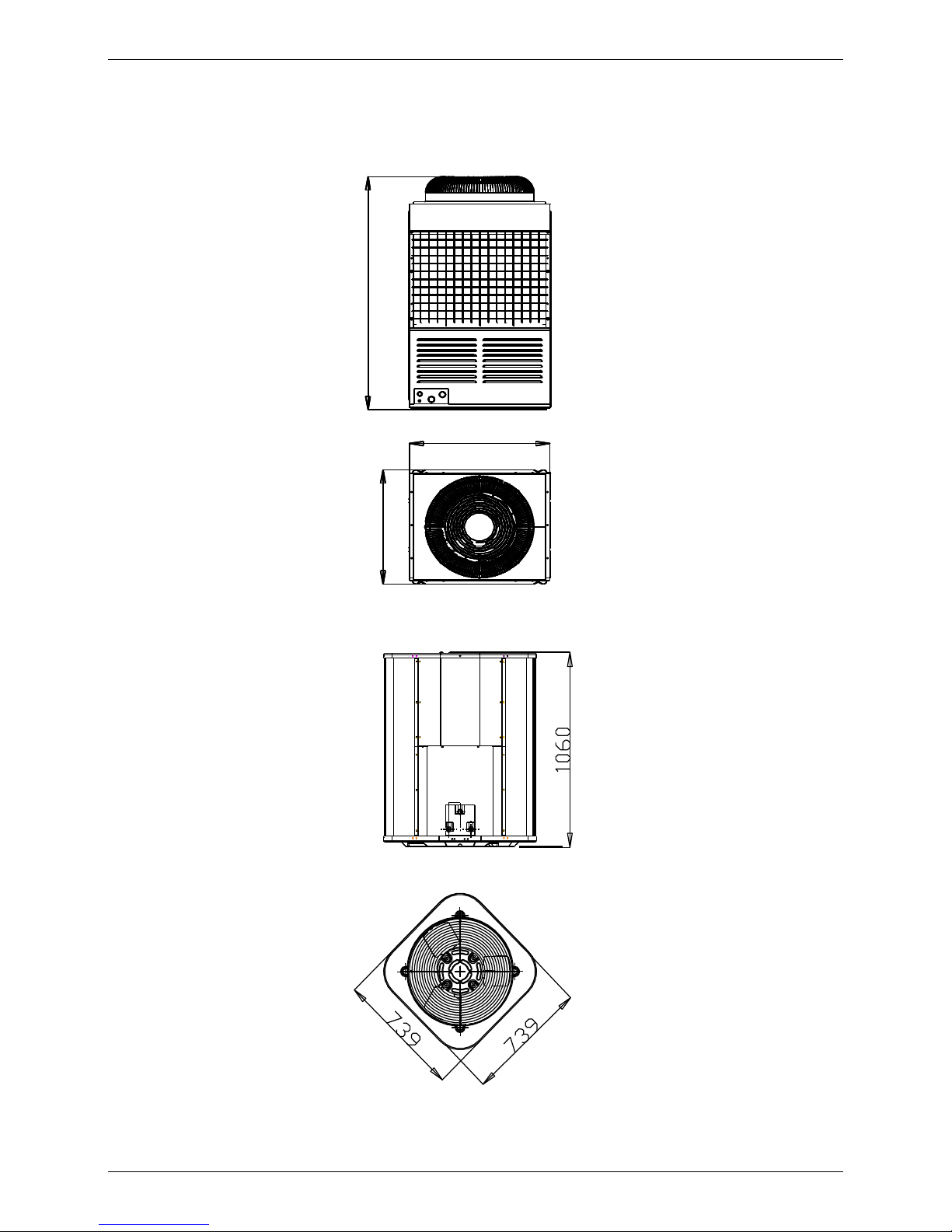
1. Measurements
Model
Dimension (mm)
Net/ Gross Weight
Power Supply
RSJ-100/N1-540V-D
Width: 750
Height: 1100
Depth: 750
121/129
220~240V-1ph-50Hz
RSJ-200/SN1-540V-D
Width: 750
Height: 1100
Depth: 750
145/152
340~420V-3ph-50Hz
RSJ-380/SN1-820-D
Width: 992
Height:1750
Depth:893
290/297
340~420V-3ph-50Hz
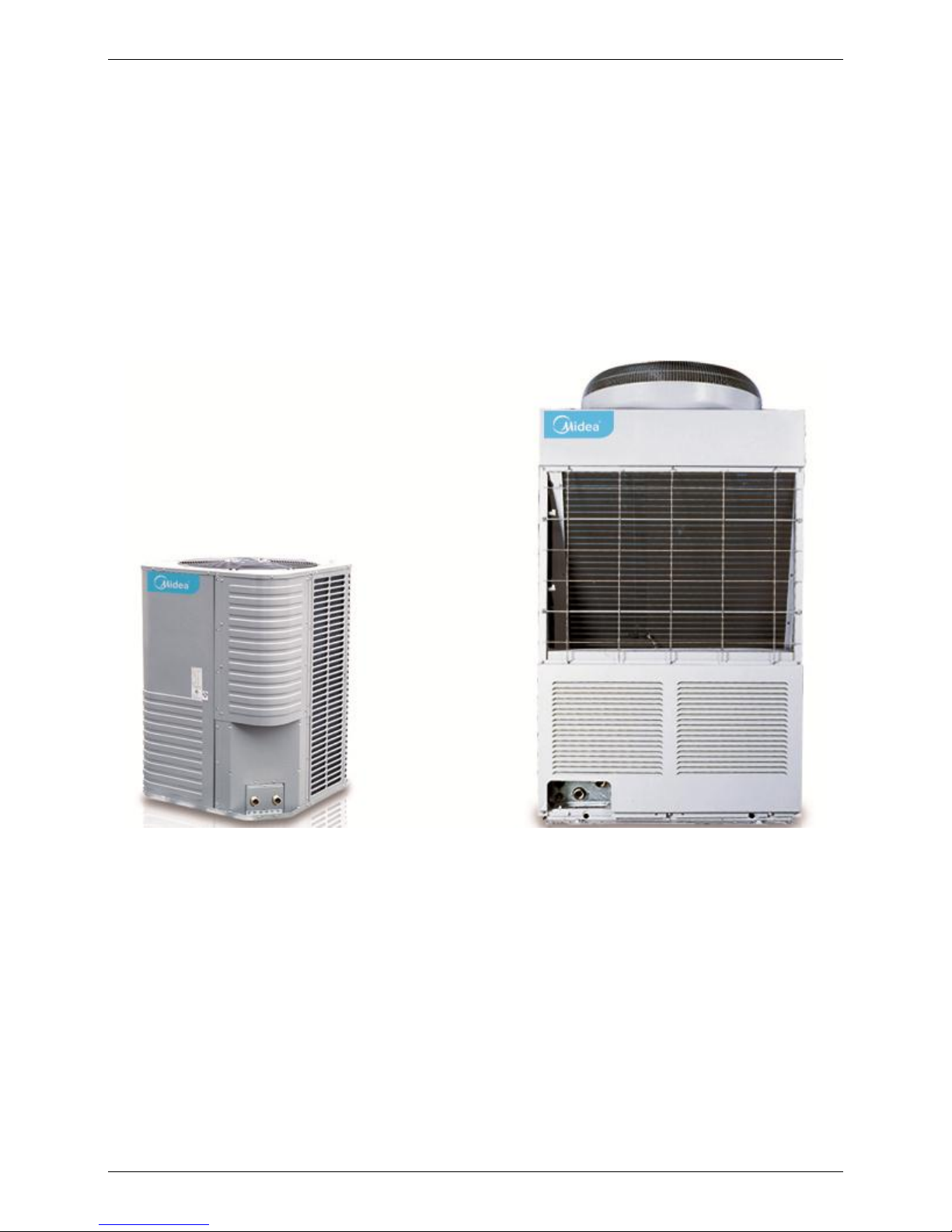
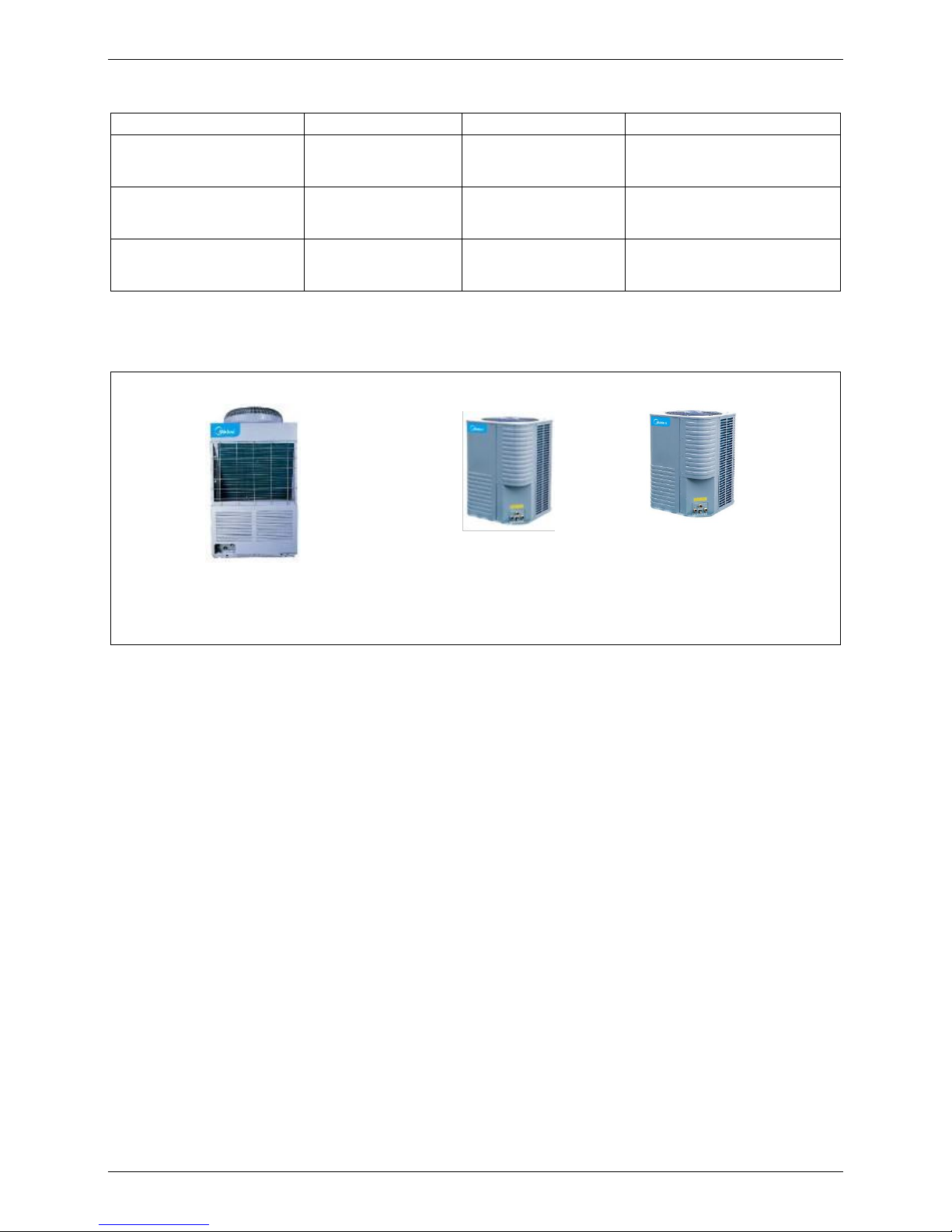
2. External Appearance
RSJ-380/SN1-820-D
RSJ-200/SN1-540V-D
RSJ-100/N1-540V-D
Page 5
MCAC-RTSM-2013-12 Midea High-temperature Direct-heating Heat Pump Water Heater Technical Manual
5
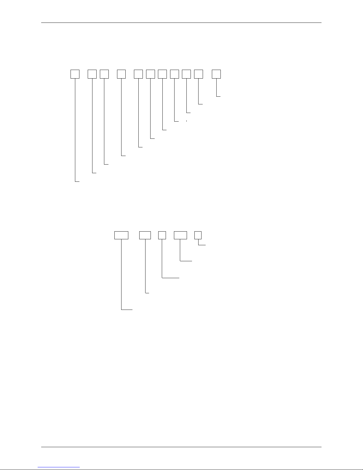
3. Nomenclature
Commercial Water Heating Unit
1
2 3
4 5
6
7
8
-
Installation type code
Water heating unit code
Export model code
/
-
9 10
Power supply specification code
Heating mode code
Rated hot water output, unit: 100 W
Water tank volume, unit: L
Other functions code
Water supply pump lift code
Refrigerant code
11
-
Design code
For example:
S
820
RSJ
-
B
- -
/
380
Configuration code
Power supply specification cod
Water heating unit code
Rated hot water output, unit: 100 W
Refrigerant code
Page 6

MCAC-RTSM-2013-12 Midea High-temperature Direct-heating Heat Pump Water Heater Technical Manual
6
4. Features
4.1 Safety
a. Complete isolation between water and electricity. No electric shock problem, more safety.
b. No fuel tubes and storage, no potential danger from oil leakage, fire, explosion etc.
4.2 Easy operation
The system can be controlled simply through the wired controller.
4.3 Automatic control:
Automatic start-up and shutdown, automatic defrosting. Save you much extra operation.
4.4 Rapid speed to produce hot water.
4.5 High efficiency and energy saving.
The unit adopts heat pump principle, which absorbs heat from outdoor air and produce heat water, thermal
efficiency can be approximately 4.9.
4.6 All-the-weather running.
Within the temperature range from -15℃ to 43℃, it will not be affected by night, overcast sky, rain and
snow.
4.7 Modular design, maximum connection 16sets basic unit
Page 7

MCAC-RTSM-2013-12 Midea High-temperature Direct-heating Heat Pump Water Heater Technical Manual
7
Part 2
Outdoor Units
1. Specifications ........................................................................................ 8
2. Capacity tables .................................................................................... 10
3. Dimensions .......................................................................................... 13
4. Service Space ...................................................................................... 14
5. Wiring Diagrams .................................................................................. 15
6. Piping Diagrams .................................................................................. 20
Page 8
MCAC-RTSM-2013-12 Midea High-temperature Direct-heating Heat Pump Water Heater Technical Manual
8
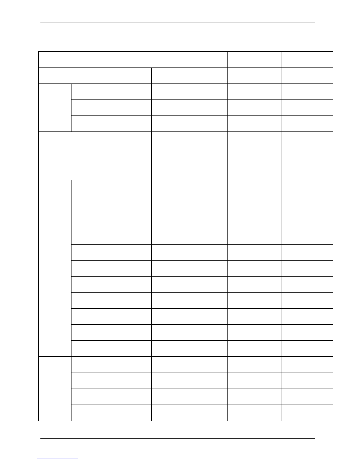
1. Specifications
HPWH SPECIFICATION
Model
RSJ-100/N1-540V-D
RSJ-200/SN1-540V-D
RSJ-380/SN1-820-D
Power supply
Ph-V-Hz
1-220-50
3-380-50
3-380-50
Water
Heating
Capacity
kW
11.2
20.4
43
Input
kW
2.85
5.2
10.5
Rated current
A
13.8
9.5
15.9
Max. input consumption
kW
3.97
7.5
15.26
Max. input current
A
18.2
13
26.7
starting current
A
98
74
74
Compressor
Model
ZP36KSE-PFZ-522
ZP67KCE-TFD-522
ZP67KCE-TFD-420
Type
SCROLL
SCROLL
SCROLL
Brand
COPELAND
COPELAND
COPELAND
Supplier
EMERSON
EMERSON
EMERSON
Capacity
kW
8.8
16.2
16.2
Input
kW
2.94
5.2
5.2
Rated current(RLA)
A
13.6
9.1
9.1
Locked rotor Amp(LRA)
A
98
74
74
Thermal protector
℃
145
135
135
Capacitor
uF
80μF/440V
/
/
Refrigerant oil
POE
POE
POE
outdoor fan
motor
Model
YDK140-6N
YDK220-6R
YDK550-6E
Brand
welling
Changzhouyongan
Changzhouyongan
Input
W
230×1
360
810/680
Capacitor
uF
12
12
25
Page 9
MCAC-RTSM-2013-12 Midea High-temperature Direct-heating Heat Pump Water Heater Technical Manual
9
Speed(hi/lo)
r/min
735 / 530
905/730
850/750
outdoor coil
a. Number of rows
1 2
2×2
b. Tube pitch(a)x row pitch(b)
mm
25.4X0
25.4X22
25.4X22
c. Fin spacing
mm
1.8
1.8
1.8
c. Fin type
Hydrophilic
aluminum
Hydrophilic
aluminum
Hydrophilic
aluminum
d. Tube outer diameter and type
mm
Ф9.52 inner groove
tube
Ф9.52 inner groove
tube
Ф9.52 inner groove
tube
e. Coil length x height x width
mm
1378×1016×22
1378×1016×44
855×969×22*2
G .Number of circuits
8 18
12*2
Outdoor noise level
dB(A)
61
61
62
Outdoor
unit
Dimension (W×H×D)
mm
750×1100×750
750×1100×750
992×1750×893
Packing (W×H×D)
mm
770×1160×770
770×1160×770
1075×1920×920
Net/Gross weight
kg
121 / 129
145 / 152
290 / 297
Refrigerant type/Quantity
Kg
R410a 1.5
R410a 2.8
R410a 5.7
Design pressure
MPa
4.4/2.6
4.4/2.6
4.4/2.6
Ambient temp
℃
(-15~43)
(-15~43)
(-15~43)
water pipe
Diameter, water inlet pipe
mm
DN25
DN25
DN25
Diameter, water outlet pipe
mm
DN25
DN25
DN25
Hot Water Yield
m3/h
0.25
0.52
1.0
Wire controller
KJR-51/BMKE-A
KJR-51/BMKE-A
KJR-51/BMKE-A
Out water Temp
℃
(default)56℃,
40℃~60℃
(default)56℃,
40℃~60℃
(default)56℃,
40℃~60℃
1. The test conditions: outdoor temp. 20/15℃(DB/WB), inlet water temp. 15℃, outlet water temp. 55℃.
2. The operation range:-15℃~43℃.
3. The specification may be changed for product improvement, please refer to the nameplate.
Page 10
MCAC-RTSM-2013-12 Midea High-temperature Direct-heating Heat Pump Water Heater Technical Manual
10
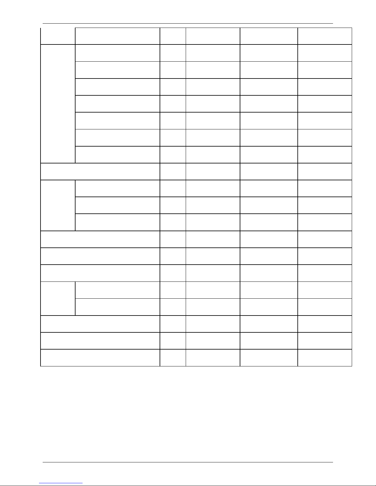
2. Capacity tables
Note: OT – Outdoor Temperature (DB);
Mode
OT(℃)
Inlet water
temperature (℃)
Outlet water
temperature(℃)
Capacity(kW)
COP
DB
WB
RSJ-100/N1-540V-D
20
15
15
40
11.37
4.56
15
45
11.48
4.36
15
50
11.47
4.09
15
55
11.41
3.82
15
60
11.30
3.53
15
12
9
40
10.50
4.23
9
45
10.88
4.29
9
50
10.89
4.03
9
55
10.81
3.76
9
60
10.67
3.48
10
8
9
40
9.67
3.84
9
45
9.63
3.43
9
50
10.05
3.60
9
55
9.96
3.45
9
60
9.22
3.04
5
4
9
40
8.91
3.46
9
45
9.06
3.39
9
50
9.16
3.24
9
55
9.22
3.13
9
60
8.85
2.90
0
–
9
40
7.69
3.14
9
45
7.69
2.99
9
50
6.62
2.51
9
55
6.53
2.34
9
60
6.51
2.20
-5
–
9
40
6.68
2.86
9
45
6.64
2.67
9
50
6.67
2.49
9
55
6.15
2.22
9
60
5.59
1.86
-10
–
9
40
5.40
2.34
9
45
5.18
2.06
9
50
5.05
1.91
9
55
4.95
1.78
-15
–
9
40
4.22
1.84
9
45
4.21
1.73
9
50
4.19
1.62
9
55
3.06
1.20
Page 11
MCAC-RTSM-2013-12 Midea High-temperature Direct-heating Heat Pump Water Heater Technical Manual
11
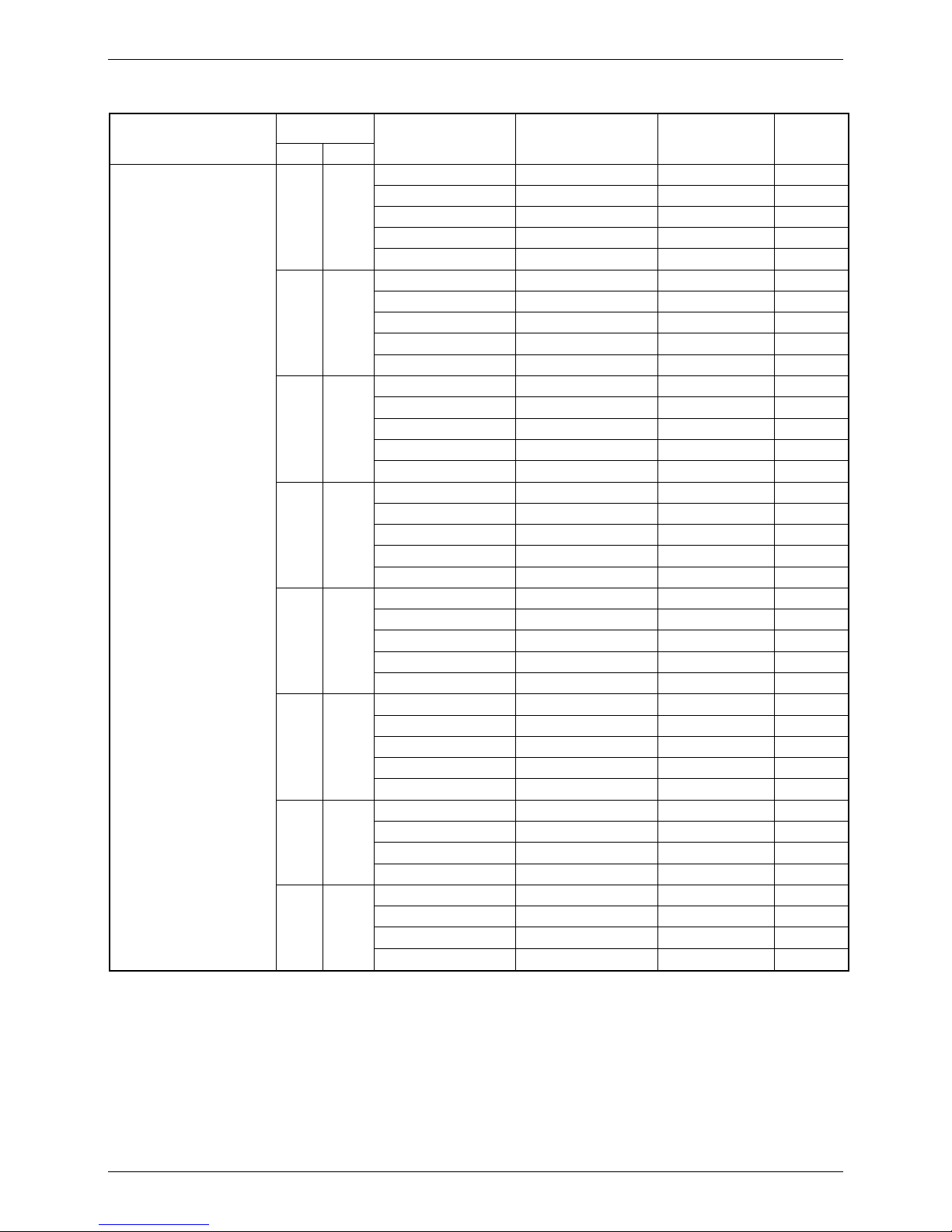
Mode
OT(℃)
Inlet water
temperature (℃)
Outlet water
temperature(℃)
Capacity(kW)
COP
DB
WB
RSJ-200/SN1-540V-D
20
15
15
40
20.88
4.75
15
45
21.00
4.48
15
50
20.99
4.20
15
55
21.85
4.00
15
60
20.05
3.76
15
12
9
39
19.62
4.45
9
45
19.90
4.28
9
50
19.89
4.02
9
55
19.54
3.90
9
60
18.96
3.60
10
8
9
41
17.56
3.85
9
45
17.47
3.91
9
50
18.09
3.75
9
55
17.97
3.57
9
60
17.34
3.32
5
4
9
40
16.21
3.80
9
45
16.63
3.66
9
50
16.51
3.42
9
55
16.20
3.31
9
60
15.98
3.14
0
–
9
41
14.42
3.27
9
45
14.67
3.17
9
50
13.98
2.99
9
55
13.83
2.73
9
57
13.47
2.58
-5
–
9
40
13.14
3.14
9
45
13.10
2.97
9
50
12.75
2.73
9
55
11.04
2.42
9
57
10.42
2.24
-10
–
9
40
10.48
2.67
9
45
10.08
2.41
9
50
9.69
2.18
9
53
9.10
2.04
-15
–
9
40
8.72
2.29
9
45
8.57
2.09
9
50
8.59
1.96
9
53
7.99
1.72
Page 12
MCAC-RTSM-2013-12 Midea High-temperature Direct-heating Heat Pump Water Heater Technical Manual
12
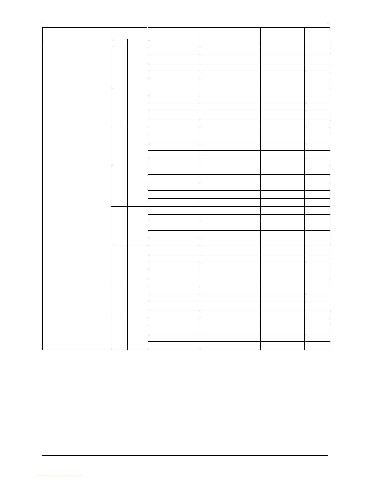
Mode
OT(℃)
Inlet water
temperature (℃)
Outlet water
temperature(℃)
Capacity(kW)
COP
DB
WB
RSJ-380/SN1-820-D
20
15
15
40
43.00
5.07
15
45
42.88
4.70
15
50
42.41
4.35
15
55
42.21
4.12
15
60
40.72
3.79
15
12
9
40
40.32
4.90
9
45
40.04
4.53
9
50
39.56
4.19
9
55
38.46
3.96
9
60
37.04
3.61
10
8
9
40
36.48
4.48
9
45
35.84
4.07
9
50
34.89
3.69
9
55
33.67
3.36
9
60
32.15
3.08
5
4
9
40
31.71
3.89
9
45
30.58
3.48
9
50
30.04
3.19
9
55
29.21
2.97
9
60
28.01
2.71
0
–
9
40
25.51
3.16
9
45
25.43
2.95
9
50
24.94
2.74
9
55
24.89
2.55
9
60
23.99
2.39
-5
–
9
40
21.77
2.75
9
45
20.92
2.47
9
50
20.79
2.33
9
55
20.12
2.20
9
60
19.71
2.05
-10
–
9
40
18.51
2.38
9
45
18.10
2.19
9
50
17.37
1.99
9
53
16.55
1.84
-15
–
9
40
14.81
1.95
9
45
14.41
1.80
9
50
14.02
1.66
9
53
13.23
1.35
Page 13
MCAC-RTSM-2013-12 Midea High-temperature Direct-heating Heat Pump Water Heater Technical Manual
13
3. Dimensions
RSJ-380/SN1-820-D
RSJ-100/N1-540V-D RSJ-200/SN1-540V-D
998
865
1765
998
865
1765
998
865
1765
Page 14
MCAC-RTSM-2013-12 Midea High-temperature Direct-heating Heat Pump Water Heater Technical Manual
14
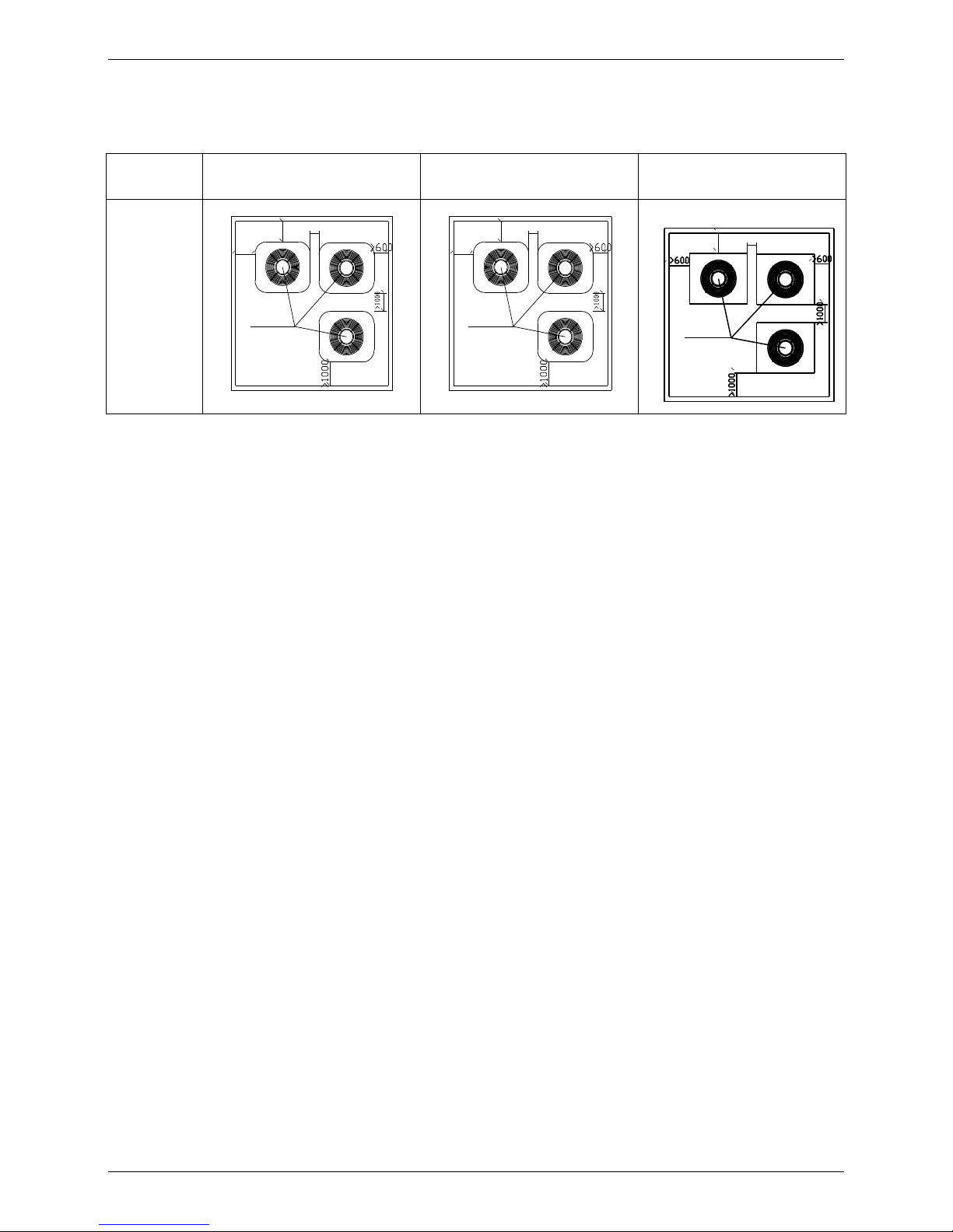
4. Service Space
Make sure that enough space for maintenance and air inlet is left when installing (as
diagrams below)
Model
RSJ-100/N1-540V-D
RSJ-200/SN1-540V-D
RSJ-380/SN1-820-D
Maintenance
space
>600
>1000
>400
Heat pump water heating unit
>600
>1000
>400
Heat pump water heating unit
>600
>400
Heat pump water heating unit
Note: The air outlet of the unit at the top cannot be blocked. If there are obstacles above it, keep the unit at least 2000 mm
away from them.
Page 15
MCAC-RTSM-2013-12 Midea High-temperature Direct-heating Heat Pump Water Heater Technical Manual
15
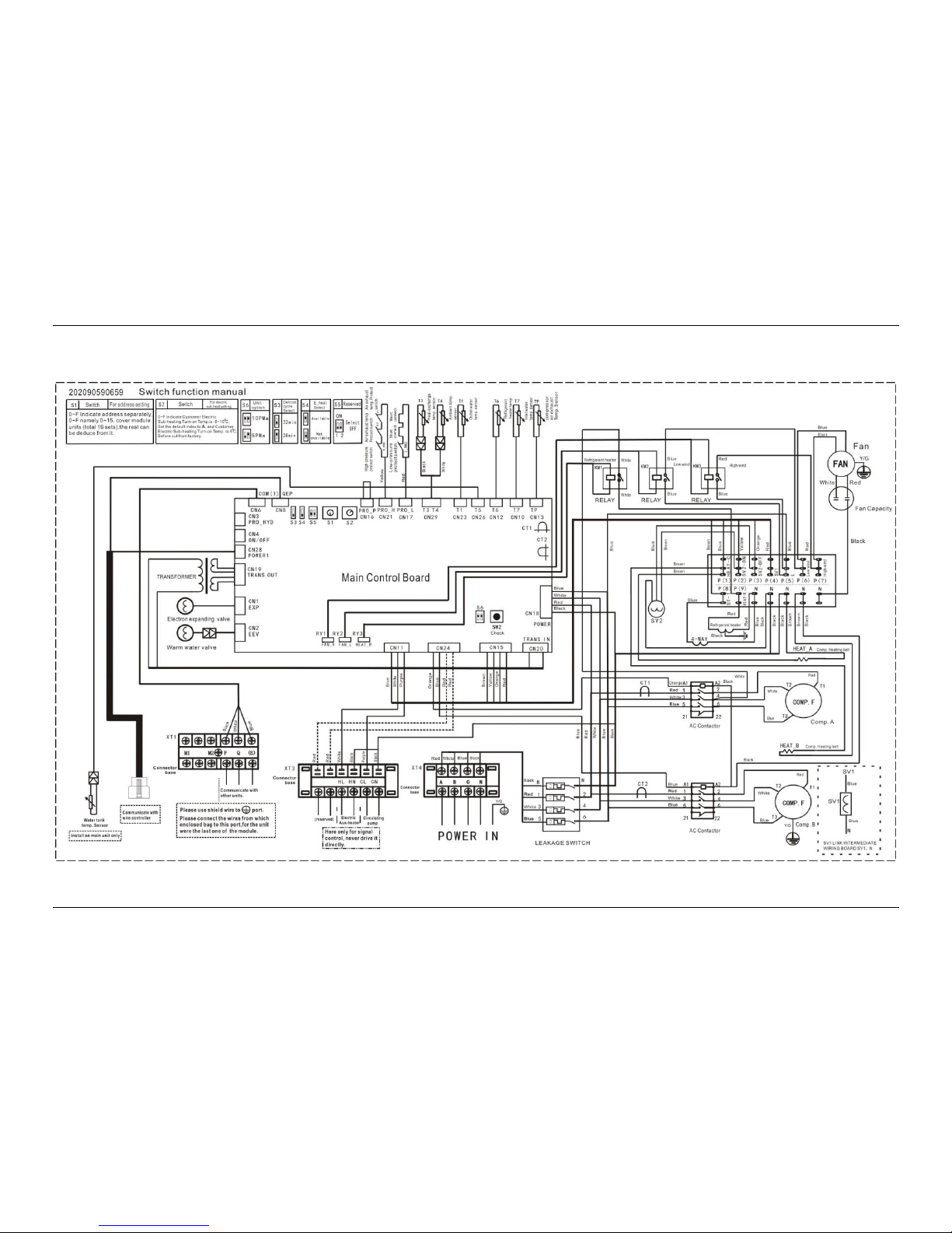
5. Wiring Diagrams
Internal wiring schematic diagram of RSJ-380/SN1-820-D
Page 16
MCAC-RTSM-2013-12 Midea High-temperature Direct-heating Heat Pump Water Heater Technical Manual
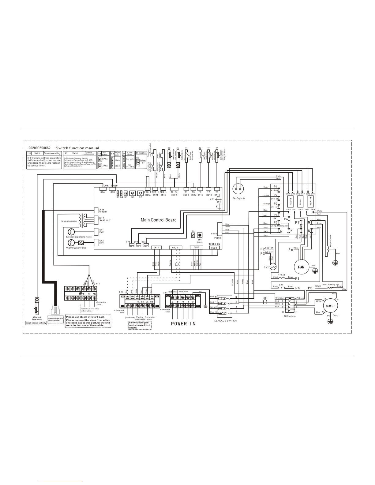
16
Internal wiring schematic diagram of RSJ-200/SN1-540V-D
Page 17

MCAC-RTSM-2013-12 Midea High-temperature Direct-heating Heat Pump Water Heater Technical Manual
17
Internal wiring schematic diagram of RSJ-100/N1-540V-D
Page 18

MCAC-RTSM-2013-12 Midea High-temperature Direct-heating Heat Pump Water Heater Technical Manual
18
Main Control Board Interface
Page 19
MCAC-RTSM-2013-12 Midea High-temperature Direct-heating Heat Pump Water Heater Technical Manual
19
Ports explanation
No.
Port explanation
No.
Port explanation
1
Low-Pressure Protection Short Connection
2
Digital Tube
3
Defrosting Cycle Select
4
E-Heater Select
5
Reserved
6
Address Setting Dip
7
Electric-Heating Temperature Setting Dip
8
Heat-Exchanger Temp. Sensor And Ambient
Temp. Sensor
9
Outlet Water Temperature Sensor
10
Water Tank Temperature Sensor
11
Refrigerant Heater Temperature Sensor
12
Inlet Water Temperature Sensor
13
Compressor Air Exhaust Temperature
Sensor
14
1# Compressor Current Transformer
15
2# Compressor Current Transformer
16
Power Interface
17
Fuse(5A)
18
Transformer Input Port
19
Controlling Wire (Defrosting Valve, By-Pass
Solenoid Valve, Circulating Water Pump And
Crankcase Heating Zone)
20
Inspection Button
21
Model Selection Dip
22
Alarm Controlling Wire
23
Main Chip
24
E-Heater And Circulating Pump Controlling
Wire
25
Refrigerant Electric Heating Stick Controlling
Wire
26
Fan Low Wind Controlling Wire
27
Fan High Wind Controlling Wire
28
Warm Water Valve Port
29
Transformer Output Port
30
Electric Expanding Valve Controlling Wire
31
Protection Of HYD
32
Power 1
33
Alarm Controlling Wire
34
PQE Communication Port
35
PQE Communication Port (To Wire
Controller)
36
The Exhaust Temperature Protection Port
37
High-Pressure Protection Port
Page 20
MCAC-RTSM-2013-12 Midea High-temperature Direct-heating Heat Pump Water Heater Technical Manual
20
Tap water
Pressure-bearing
To the user
Used for pipe
network water
returning
6. Piping Diagrams
RSJ-100/N1-540V-D RSJ-200/SN1-540V-D RSJ-380/SN1-820V-D
Page 21

MCAC-RTSM-2013-12 Midea High-temperature Direct-heating Heat Pump Water Heater Technical Manual
21
Part 3
Installation
1. Precautions ................................................................................................. 22
2. Installation information .............................................................................. 23
3. Accessories ................................................................................................. 24
4. Inspecting and Handling the Unit .............................................................. 24
5. Connection Diagram ................................................................................... 25
6. Operation Instruction .................................................................................. 27
7. Installation Instruction ................................................................................ 28
8.Electric Wiring .............................................................................................. 31
Page 22

MCAC-RTSM-2013-12 Midea High-temperature Direct-heating Heat Pump Water Heater Technical Manual
22
1. Precautions
■ To prevent injury to the user or other people and property damage, the following instructions must be
followed. Incorrect operation due to ignoring of instructions may cause harm or damage.
■ The safety precautions listed here are divided into two categories. In either case, important safety
information is listed which must be read carefully.
WARNING
Failure to observe a warning may result in death.
CAUTION
Failure to observe a caution may result in injury or damage to the equipment.
WARNING
■ The water heating unit must be earthed effectively.
■ A Leakage breaker must be installed near the power supply.
■ Ask your supplier for installation of the air source heat pump water heating units. Incomplete installation
performed by yourself may result in water leakage, electric shock, or fire.
■ Ask your supplier for the repair and maintenance. Incomplete repair and maintenance may result in
water leakage, electric shock or fire.
■ In order to avoid electric shock, fire or injury, if any abnormality is detected, such as smell of fire, turn off
the power supply and call your supplier for instructions.
■ Never replace a fuse with that of wrong rated current or other wires when a fuse blows out.
Use of wrong wire or copper wire may cause the unit to break down or a fire.
■ Do not insert fingers, rods or other objects into the air inlet or outlet. When the fan is rotating at high
speed, it will cause injury.
■ Never use a flammable spray such as hair spray, lacquer paint near the unit. It may cause a fire.
■ Never touch the air outlet or the horizontal blades while the swing flap is in operation. Fingers may
become caught or the unit may break down.
■ Never put any objects into the air inlet or outlet. Objects touching the fan of high speed can be
dangerous.
■ Do not dispose this product as unsorted municipal waste. Collection of such waste separately for
special treatment is necessary.
■ The appliance shall be installed in accordance with national wiring regulations.
CAUTION
■ Do not use the air source water heater for other purposes.
■ Before cleaning, be sure to stop the operation, turn the breaker off or pull out the supply cord.
Otherwise, an electric shock and injury may result.
■ Be sure the water heating unit is grounded.
In order to avoid electric shock, make sure that the unit is grounded.
■ In order to avoid injury, do not remove the fan guard of the outdoor unit.
■ Do not operate the air source water heater with a wet hand. An electric shock may happen.
■ Do not touch the heat exchanger fins. These fins are sharp and could result in cutting injuries.
■ Do not place items which might be damaged by moisture under the indoor unit.
Condensation may form if the humidity is above 80%, the drain outlet is blocked or the filter is polluted.
■ After a long use, check the unit stand and fitting for damage. If damaged, the unit may fall and result in
injury.
■ To avoid oxygen deficiency, ventilate the room sufficiently if equipment with burner is used together with
the air conditioner.
■ Arrange the drain hose to ensure smooth drainage. Incomplete drainage may cause wetting of the
building, furniture etc.
Page 23

MCAC-RTSM-2013-12 Midea High-temperature Direct-heating Heat Pump Water Heater Technical Manual
23
■ Never touch the internal parts of the controller. Do not remove the front panel. Some parts inside are
dangerous to touch, and a machine trouble may happen.
■ Never expose little children, plants or animals directly to the air flow. Adverse influence to little children,
animals and plants may result.
■ The appliances connected to the water mains
the maximum inlet water pressure is 0.7Mpa
the minimum inlet water pressure is 0.2Mpa
maximum water temperatures is 55℃ and minimum water temperatures is 48℃.
■ That the appliance shall be installed in accordance with national wiring regulations.
■ The means for disconnection from a power supply shall be incorporated in the fixed wiring and have an
air gap contact separation of at lease 3mm in each (phase) conductor.
2. Installation information
■ Enough space is installation and maintenance shall be preserved.
■ The air inlet and outlet should be free from obstacles and strong wind.
■ The bearing surface should be flat, able to bear weight of the unit and suitable for installing the unit
horizontally without increasing noise or vibration.
■ The operation noise and air flow expelled shall not affect neighbors.
■ No flammable gas is leaked nearby.
■ It is convenient for piping and wiring.
CAUTION
■ Installing the equipment in any of the following places may lead to malfunction of the equipment (if it is
inevitable, consult the supplier):
1) The site contains mineral oils such as cutting lubricant.
2) Seaside where the air contains much salt.
3) Hot spring area where corrosive gases exist, e.g., sulfide gas.
4) Factories where the power voltage fluctuates seriously.
5) Inside a car or cabin.
6) Place like kitchen where oil permeates.
7) Place where strong electromagnetic waves exist.
8) Place where flammable gases or materials exist.
9) Place where acid or alkali gases evaporate.
10) Other special environments.
■ Precautions before installation
1) Decide the correct way of conveying the equipment.
2) Try to transport this equipment with the original package.
3) If the unit has to be installed on a metal part of the building, electric insulation must be installed,
and the installation must meet the relevant technical standards for electric devices.
■ Installation space
Before installing the unit, reserve the space of maintenance shown in the following figure.
Page 24
MCAC-RTSM-2013-12 Midea High-temperature Direct-heating Heat Pump Water Heater Technical Manual
24
3. Accessories
Please check whether the following fittings are of full scope. If there are some spare fittings, please restore
them carefully.
NO.
Name
Quantity
Application
1
Installation and Operation Manual
1
——
2
Wire controller module
1
Status of the control unit and
display unit
3
Water tank temperature sensor
1
Water tank temperature check
4
Y type filter
1
Inlet water filter
4. Inspecting and Handling the Unit
After delivery, the package should be checked and any damage should be reported immediately to the
carrier claims agent.
When handling the unit, take into account the following:
1. Fragile, handle the unit with care.
Keep the unit upright in order to avoid compressor damage.
2. Choose before hand the path along which the unit is to be brought in.
3. Move this unit with original package.
4. When lifting the unit, always use protectors to prevent belt damage and pay attention to the balance of
the unit’s gravity.
Page 25
MCAC-RTSM-2013-12 Midea High-temperature Direct-heating Heat Pump Water Heater Technical Manual
25
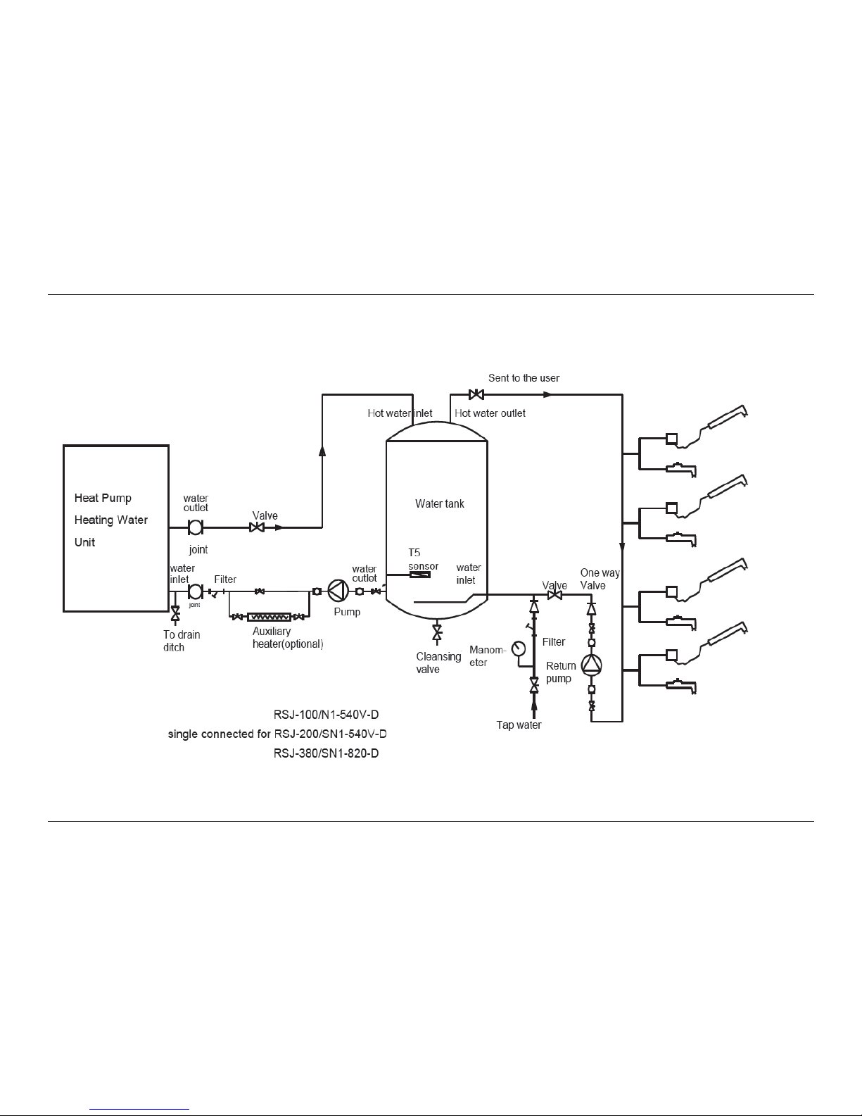
5. Connection Diagram
5.1 Single Unit Connection Diagram
Page 26

MCAC-RTSM-2013-12 Midea High-temperature Direct-heating Heat Pump Water Heater Technical Manual
26
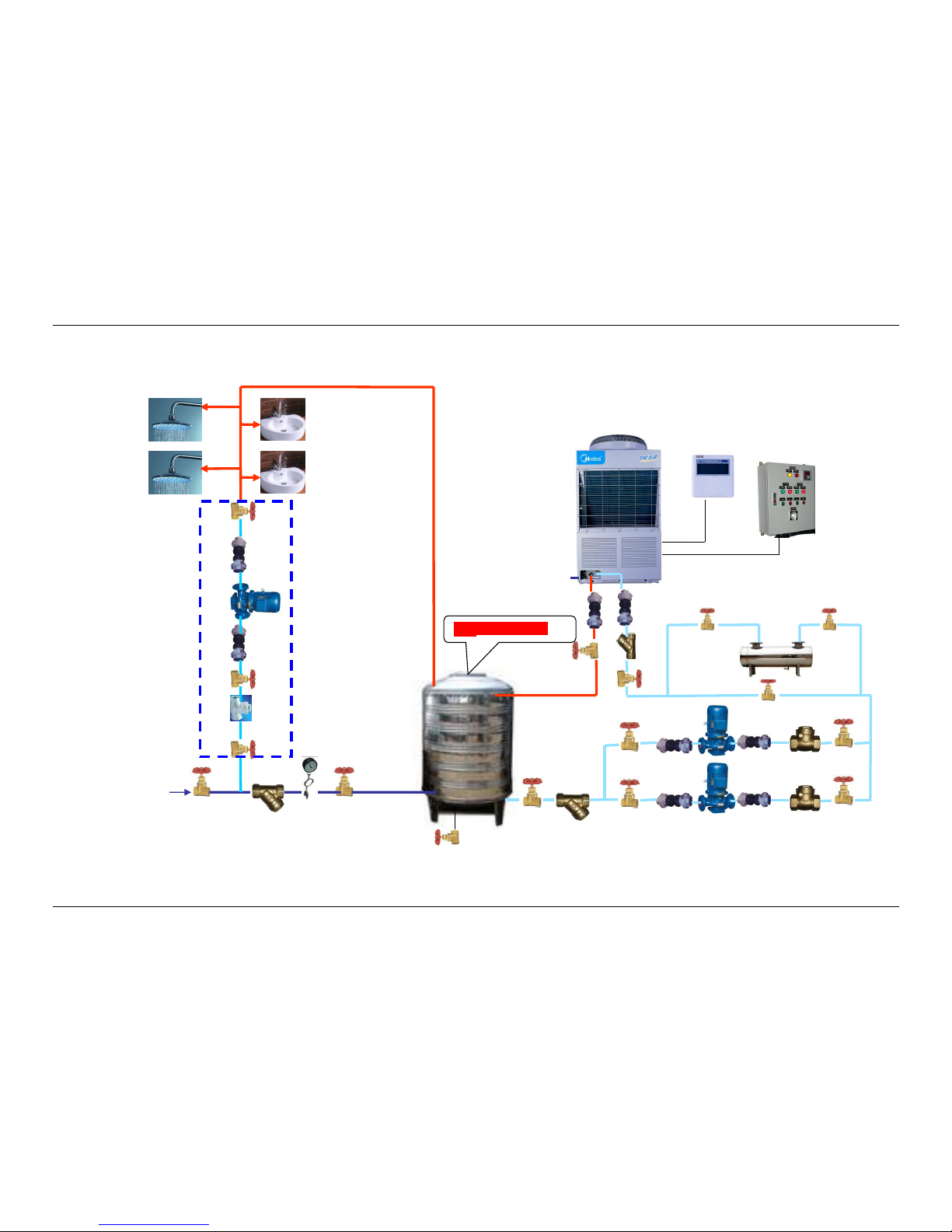
5.2 Multiple Unit Connection Diagram
Page 27

MCAC-RTSM-2013-12 Midea High-temperature Direct-heating Heat Pump Water Heater Technical Manual
27
6. Operation Instruction
1. This type of heat pump is designed to connect with a pressure-bearing tank. While installing, please
refer to the recommended connection diagram in the owner’s manual. If it is needed to be connected
with an open tank, the water level controlling and the water cycling heating controlling should be realized
in projecting. It is relatively a bit complex. In this condition, we suggest to adopt the C series of the
commercial direct-heating type.
2. Water heating: The water output temperature range is 40℃~60℃ (default 56℃). When the water
temperature(T5) in the tank is 2℃ (or even more) lower than the stopped temperature of the heat pump(T
stop), the unit will star working automatically until the water temperature(T5) reaches up to (or even higher
than) the stopped temperature(T stop). The temperature of hot water outlet can achieve the setting
temperature only by an once-through circulation.
3. Hot water supply: There is no need to use an additional hot water pump to boost the hot water to the end
users since the storage tank is a pressurized type. If the pressure of the tap water is not stable, an
one-way valve is suggested to be located near the cold water inlet of the tank.
4. Pipe network return (not essentially for the hot water supplying system): When the return temperature
controller detects that the water temperature in the pipe is lower than the lower limit of the return temperature
(set at 40 ℃ ~ 45 ℃), the return controlling solenoid valve will open. Then, the hot water returning pump will
open. The hot water will enter the pipeline and the cold water will return back to the water tank. When the
temperature controller detects that the water temperature is higher than the upper limit of the return water
temperature (set at 45 ℃ ~ 50 ℃), the return solenoid valve and the hot water supplying pump will close by
order. Then, the pipe network returning will stop. (This manner can only be realized in the project and the
main unit of the heat pump cannot control it. This is only one of the pipe network return manner and other
manners can be selected according to different projects.)
Page 28

MCAC-RTSM-2013-12 Midea High-temperature Direct-heating Heat Pump Water Heater Technical Manual
28
7. Installation Instruction
7.1. Y-type filter must be installed in the inlet pipeline
A brass DN25 mode Y-type filter in 80 meshes is equipped with each finished unit of the
RSJ-380/SN1-820-D, RSJ-200/SN1-540V-D and RSJ-100/N1-540V-D model. The filter is required to be
installed in the water inlet pipeline at the place closed to the water tank, otherwise, the filter and
high-precision temperature valve inside the unit might be blocked out by dirt.
7.2. The selection of lift and flow of the circulating pump
The circulating pump requires for large flow and the rated flow should be more than 6 m3/h for
RSJ-380/SN1-820-D, 4 m3/h for RSJ-200/SN1-540V-D and 2 m3/h for RSJ-100/N1-540V-D. The lift of
the pump is sampled according to the hydraulic calculation.
7.3. The fall between the main unit and the hot water tank
The lift of the circulating pump should be corresponded to the fall between the main unit
and the hot water tank. If it is not big enough, some protecting code may appear while
running and the unit will stop.
7.4. Installation Water Tank
7.4.1 The hole site of the tank
Remark:
1. The diameter of the cycle water inlet and outlet should be in accordance with the charts of the water pipe
selection.
2. The diameter of blind pip for the location of the water temperature sensor may be about Φ8~Φ10.
3. The diameter of the tap water inlet and the hot water outlet should be determined by the maximum
hourly hot water flow of all the end water users.
Page 29

MCAC-RTSM-2013-12 Midea High-temperature Direct-heating Heat Pump Water Heater Technical Manual
29
7.4.2 Installation of the Temp. Sensor
Water Pipe Selection 7.5
RSJ-380/SN1-820-D
Unit number
Main water inlet pipeline
Main water outlet pipeline
1 set
DN25
DN25
2 sets parallel
connection
DN50
DN50
3 sets parallel
connection
DN65
DN65
4~5 sets parallel
connection
DN80
DN80
6~8 sets parallel
connection
DN100
DN100
9~12 sets parallel
connection
DN125
DN125
13~14 sets parallel
connection
DN125
DN125
15~16 sets parallel
connection
DN150
DN150
RSJ-200/SN1-540V-D
Unit number
Main water inlet pipeline
Main water outlet pipeline
1 set
DN25
DN25
2 sets parallel
connection
DN32
DN32
3 sets parallel
connection
DN50
DN50
4~5 sets parallel
connection
DN50
DN50
6~7 sets parallel
connection
DN65
DN65
8 sets parallel
connection
DN65
DN65
9~12 sets parallel
connection
DN65
DN65
13~14 sets parallel
connection
DN80
DN80
15~16 sets parallel
connection
DN80
DN80
8 blind copper pipe or
stainless steel pipe
Water tank temperature sensor
Heat conduction silica gel filling
Port airproof
water outlet
Connect 0# main unit
Page 30

MCAC-RTSM-2013-12 Midea High-temperature Direct-heating Heat Pump Water Heater Technical Manual
30
RSJ-100/N1-540V-D
Unit number
Main water inlet pipeline
Main water outlet pipeline
1 set
DN25
DN25
2 sets parallel connection
DN25
DN25
3 sets parallel connection
DN32
DN32
4~5 sets parallel connection
DN32
DN32
6~7 sets parallel connection
DN50
DN50
8~12 sets parallel connection
DN50
DN50
13~14 sets parallel
connection
DN65
DN65
15~16 sets parallel
connection
DN65
DN65
7.6. Installation pipe-hot --Heat Preservation
Formation: a. Antisepsis layer; b. Glide layer; c. Adiabatic layer:
d. Waterproof layer; e. Outer safeguard layer.
Pipe Antisepsis Formation: a. Antisepsis layer:
b. Waterproof layer; c. Outer safeguard layer.
Antisepsis layer: red lead paint
Adiabatic layer: mineral wool, rubber plastic sponge、foaming polyurethane etc
Outer safeguard layer:
Outdoor, aluminum foil sheet+0.3mm galvanized steel sheet;
Indoor, aluminum foil sheet.
Thickness of Adiabatic
layer≥30mm
Pipe
Waterproof &
Antisepsis layer
Adiabatic
layer
Page 31

MCAC-RTSM-2013-12 Midea High-temperature Direct-heating Heat Pump Water Heater Technical Manual
31
8.Electric Wiring
1. Attention
● The water heater should powered separately and the power voltage should be in line with rated
voltage..
● The power supply circuit of the water heater should be earthed, the power cord should be connected
with the external earthed line in reliable state and all the external earthed cables are effective.
● The construction of the wiring should be carried out by professionals in accordance with the circuit
diagram.
● Set up leakage protection devices in accordance with the requirements of the relevant national
technical standards.
● The power cord and the signal line should be laid neatly without cross-interfere and should not contact
with the connecting pipe and the valves.
● The unit is not equipped with power cord. Please refer to the prescribed power specification for
selecting the power cord and cross-connection between two lines are not allowed.
● Check whether all the connections are correct before powering the unit.
2. Electric Control Box Wiring Diagram
G A B C N
~380V
Wire controller
Circulating pump
Electric-heate
Page 32
MCAC-RTSM-2013-12 Midea High-temperature Direct-heating Heat Pump Water Heater Technical Manual
32
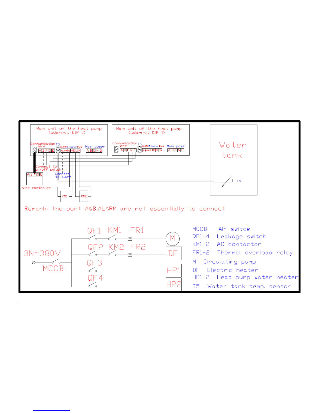
3. Electric Control Schematic Diagram of Parallel Connection of Two Units
Page 33
MCAC-RTSM-2013-12 Midea High-temperature Direct-heating Heat Pump Water Heater Technical Manual
33
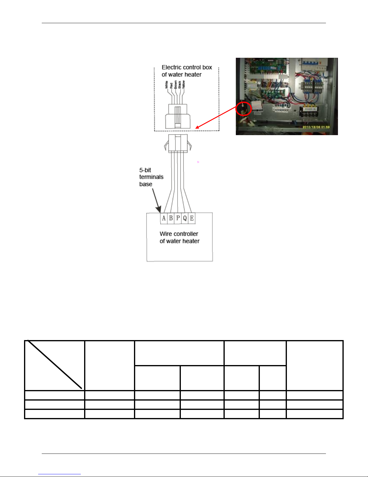
4. Connection of the wire controller
Please connect by 5-bit shielded wire in accessory bag (a 10m end-to-end wire), which length depends on
the specific situation to lengthen, but couldn’t exceed than 40 m. If a longer one you need, please consult the
factory and the dealer.
5. Power specification
Power
MIN. Cord Diameter(m ㎡)
Manual Switch (A)
Leakage Protector
Phase Wire
(Length≤30m)
Ground Wire
Capacity
Fuse
RSJ-100/N1-540V-D
220V-1PH-50Hz
6
4
50
30
30mA<0.1 sec
RSJ-200/SN1-540V-D
380V-3PH-50Hz
6
4
50
30
30mA<0.1 sec
RSJ-380/SN1-820-D
380V-3PH-50Hz
10
5
60
50
30mA<0.1 sec
Note: The wire diameter and the continuous length in the table are for the condition that the voltage drop range is within 2%.
When the continuous length of the wire exceeds the value in the table, please select proper wire diameter according to
relevant rules.
Model
Items
Page 34

MCAC-RTSM-2013-12 Midea High-temperature Direct-heating Heat Pump Water Heater Technical Manual
34
Part 4
Trial Operation
1. Confirmation before the trial operation ..................................................... 35
2. Water Pump Air Extraction ......................................................................... 35
3. Wired Controller and Operation ................................................................. 36
4. Water tank cleaning .................................................................................... 43
5. Schematic Diagram of the Unit System ..................................................... 43
6. Error Code Cause Analysis and the Solutions ......................................... 44
7. Main control board spot check .................................................................. 46
8. Failure without Code................................................................................... 46
9. Troubleshoot of abnormal phenomena ..................................................... 47
Page 35
MCAC-RTSM-2013-12 Midea High-temperature Direct-heating Heat Pump Water Heater Technical Manual
35
1. Confirmation before the trial operation
1.1 All the installation is complete.
1.2 Water heater is installed correctly.
1.3 The pipelines and wiring are correct.
1.4 The accessories are installed correctly.
1.5 The drainage is smooth.
1.6 The thermal insulation is sound.
1.7 The earthing wire is connected correctly.
1.8 The power voltage is consistent with the rated voltage of the heater.
1.9 No obstacle at the air inlet and outlet of the unit.
1.10 The leakage protector can work effectively.
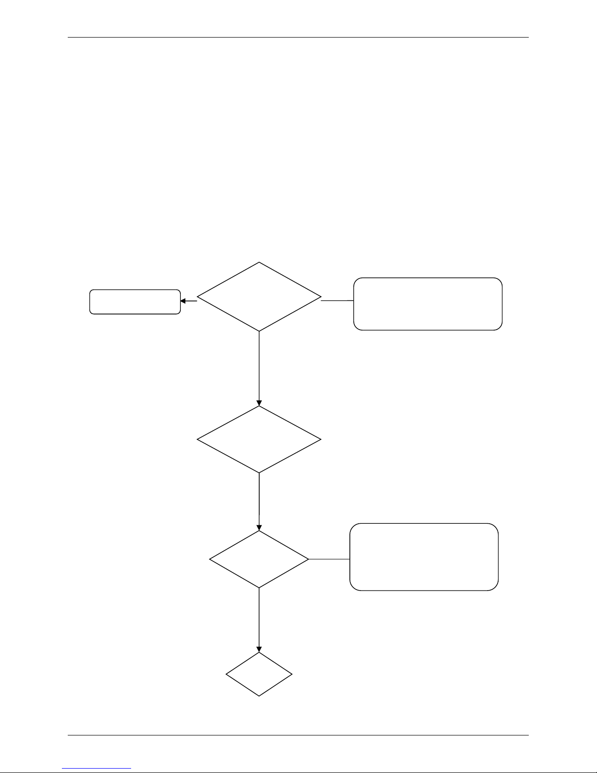
2. Water Pump Air Extraction
Exchange water pump
power line
Open the
valves on the
Y
Pipeline
air
Hit the AD conductor of the circulating
pump to inhale manually and the water
pump runs. The water is inhaled into the
pipeline and flow through the unit then
return to the tank at last. The air in the
pipe line will be discharged from the air
Y
End
Hit the AD conductor of the circulating
pump to inhale manually and release the
contactor after the pump idling. Observe
whether the running direction of the pump
impeller is correct。
Idling the water
pump for
direction
N
Page 36
MCAC-RTSM-2013-12 Midea High-temperature Direct-heating Heat Pump Water Heater Technical Manual
36
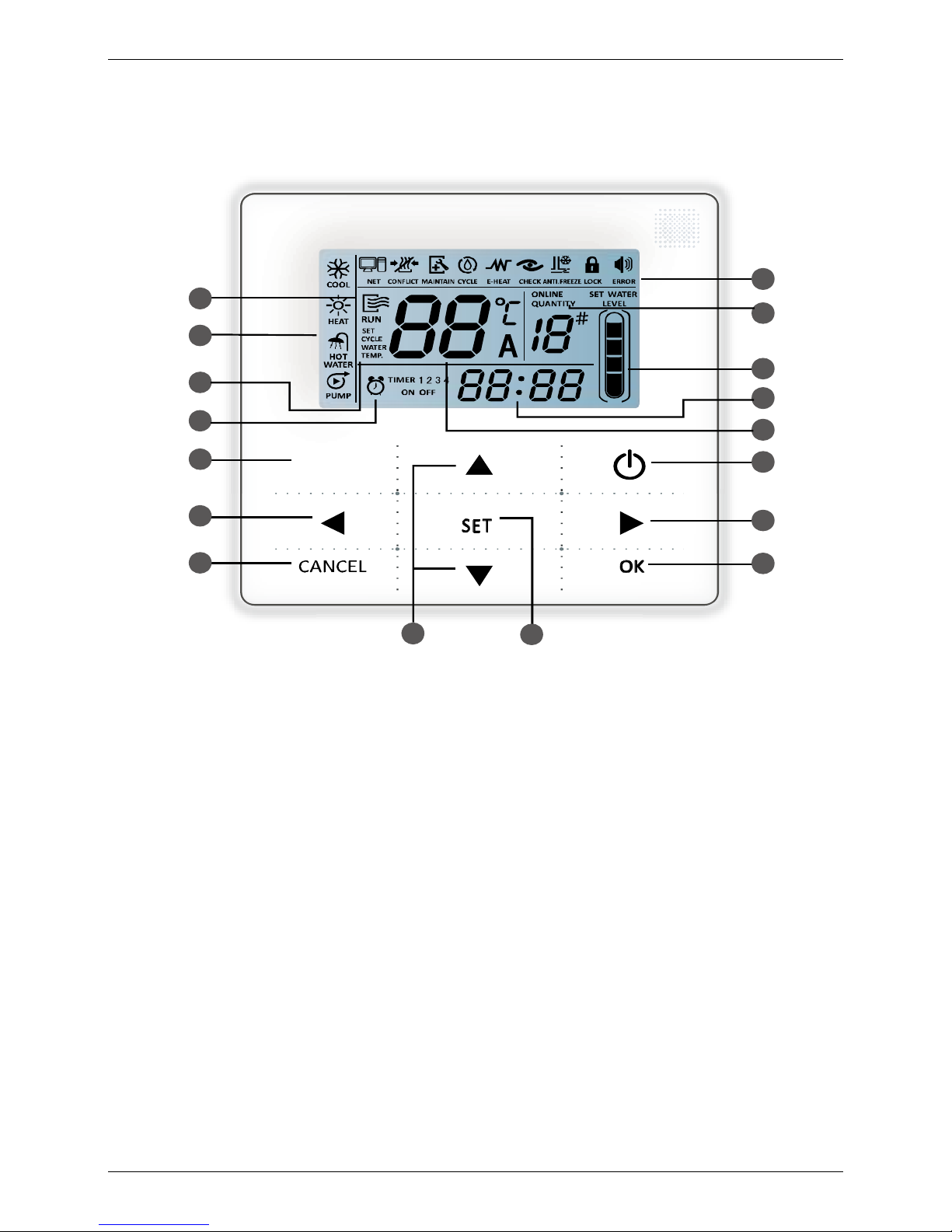
3. Wired Controller and Operation
Technical data and characteristic
1. Input voltage 10V AC
2. Operation ambient temperature of wired controller: -10℃~43℃
3. Operation relative humidity of wired controller: 40%~90%
4. Touch key operation and LED displays operation parameters
5. Multiple timer and real-time clock (battery life: 5~8 years).
14
13
3
1
2
4
16
11
15
5
6
7
8
9
10
11
12
(Press for 3sec to
cancel timer)
(Press for 3sec to
unlock)
AUXILIARY
1. Operation icon
2. Mode area
3. Setting temperature
4. Timing on/off
5. Function icon
6. On-line units quantity indication
7. Water level indication
8. Clock
9. Water temperature
10. On/Off key
11. Left/Right key
12. Confirm key
13. Set key
14. Add and reduce key
15. Cancel key
16. Auxiliary key
Page 37
MCAC-RTSM-2013-12 Midea High-temperature Direct-heating Heat Pump Water Heater Technical Manual
37
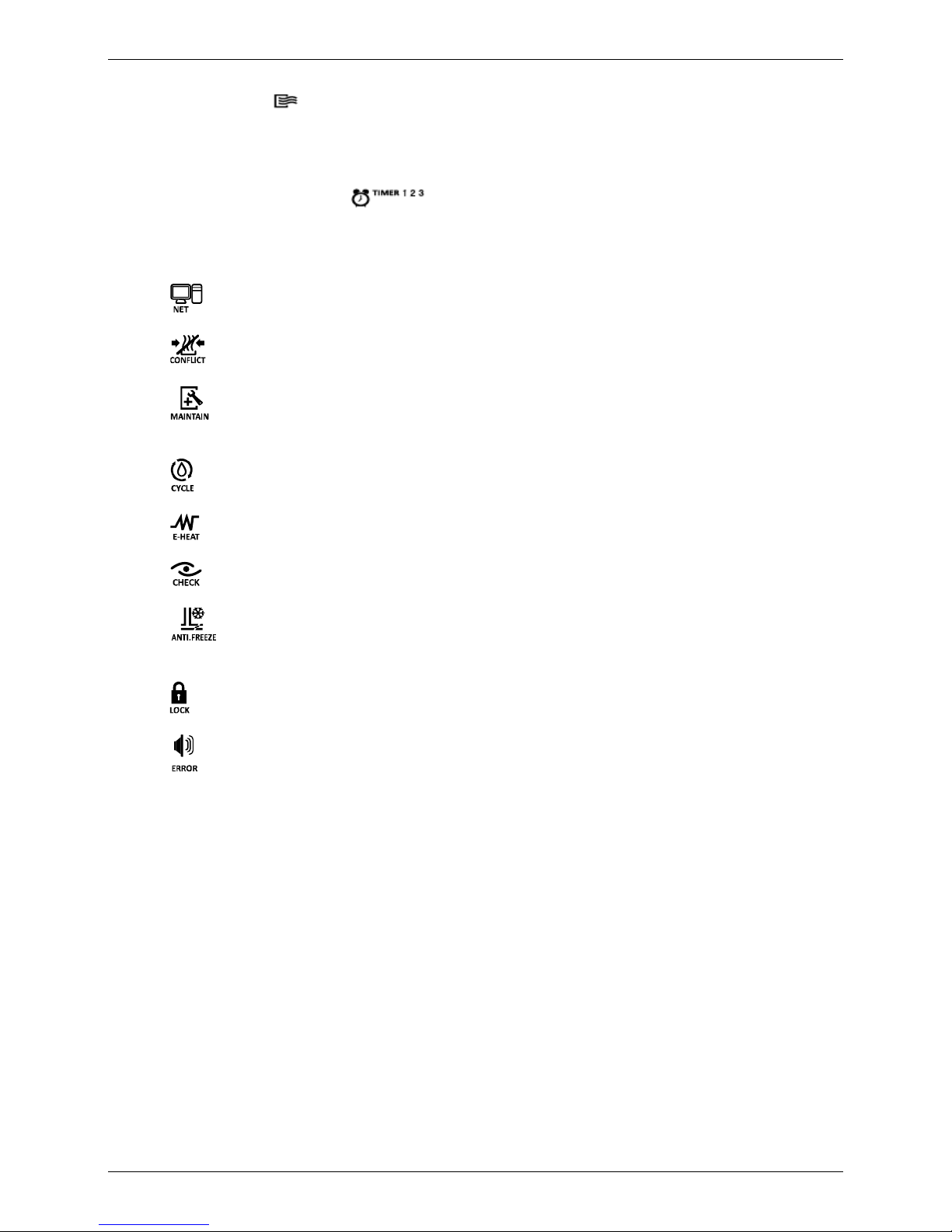
Icon description
1. Operation icon : Indication of unit ON or OFF status
2. Mode area: Indicate the main unit operation mode.
3. Setting temperature: Three statuses about water temperature, setting water temperature and
setting cycle water temperature can be displayed.
4. Timing On/OFF indication : Indicate the timing information. Three timers can be set on
the wire controller: Timer 1, Timer 2, and Timer 3. These three timers can control the main unit to turn
ON and OFF three times at most during one day.
5. Function icon:
1) : Display when water heater system connects to Modbus network;
2) : Display when other heat source is provided to the system;
3) : Display when water heater maintenance is needed. You can press and hold “AUXILIARY”
key for 3 seconds to cancel the icon and timing will restart until next maintenance;
4) : Display when cycle heating function is operational;
5) : Display when electric auxiliary heating function is operational;
6) : Display when check function is operational;
7) : Display when ambient temperature is below 2℃ which means the main unit need
anti-freezing action;
8) : Display when no key operation for 2 minutes and all keys are locked.
You can press and hold “OK” key for 3 seconds to unlock;
9) : Display when error or protection occurs and means the unit need maintenance by
professionals.
6. On-line unit qty. indication: Under normal status display the quantity of units connected to the wire
controller; under check status display the device serial number;
7. Water level indication: Under normal status displays water level; under water level setting status
displays setting value;
8. Clock: Under normal status displays clock; under timing setting displays the setting timing;
9. Water temperature: Under normal status display water temperature; under water temperature
setting status displays the setting value; under cycle heating water temperature setting status
display the setting value; under check status displays check parameter;
10. ON/OFF key: Turn on and turn off functions;
11. Right and Left key: Press these keys to check setting water temperature, setting cycle heating
water temperature and setting water level under main page; Press right key to shift to the next step
setting under timing setting status; Press these keys to turn over the unit parameter information
under check status;
Page 38
MCAC-RTSM-2013-12 Midea High-temperature Direct-heating Heat Pump Water Heater Technical Manual
38
12. OK key: Press this key to confirm settings. Press and hold this key for 3 seconds to unlock under
locking status;
13. Setting key: Setting water temperature, timing and mode etc.; Press and hold this key for 3
seconds to enter check status;
14. Add and Reduce key: Move up or move down values of temperature, timing, water level etc.; Turn
over #0~#15 units under check status;
15. Cancel key: Press this key to cancel parameter setting under setting status; Press and hold this key
for 3 seconds to cancel timing when timing is valid;
16. Auxiliary key: Power on the cycle heating function, electric auxiliary heating function or water pump
function.
Operation instruction
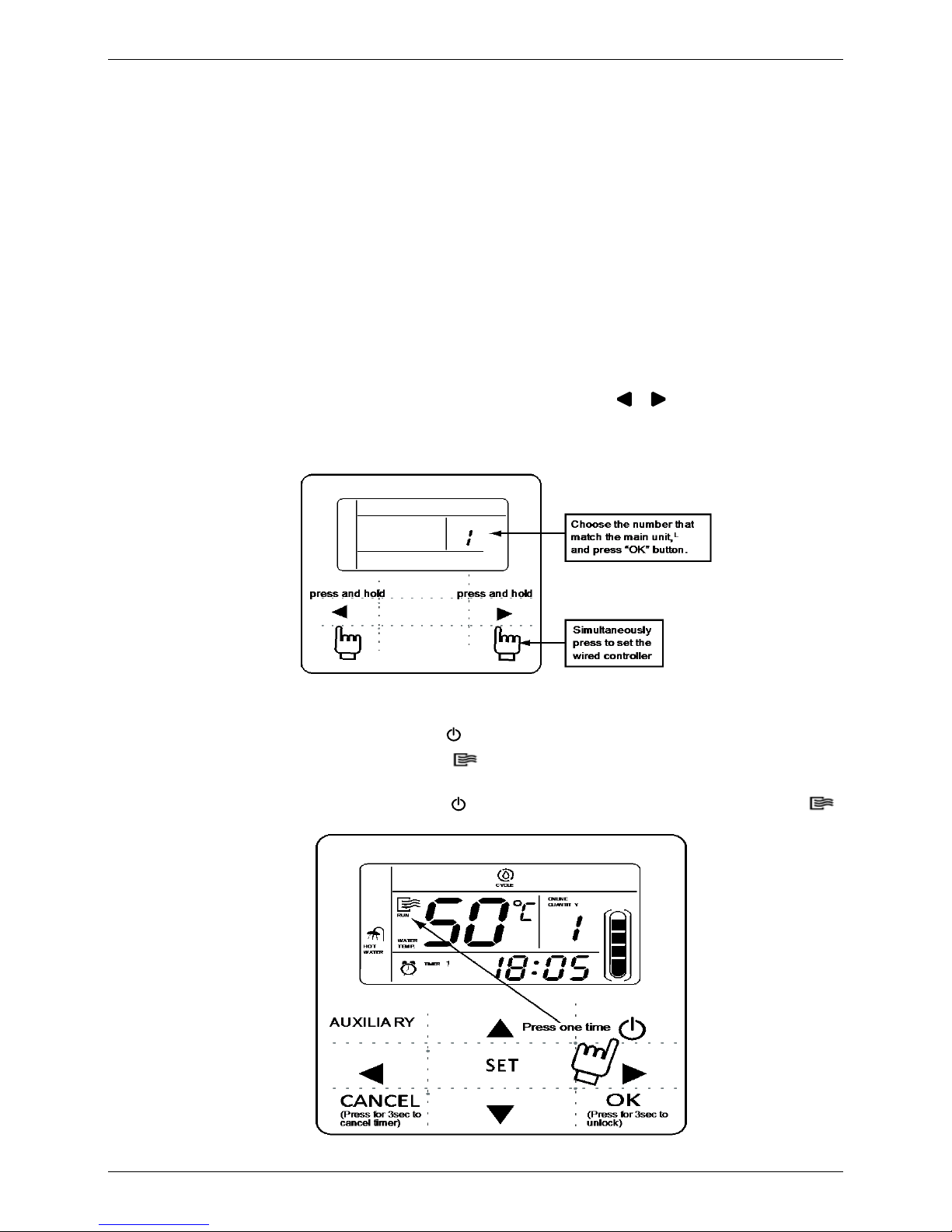
1. Setting wired controller
This controller needs setting before applying to certain HPWH models.
Setting method: When the controller is “OFF” , press and hold “ ” “ ” two buttons, waiting for
one number (1 to 5) displayed on the screen, press “▲ ”or “▼ ” button and select the number “1”
which match with the main unit, then press “OK” button to confirm.
2. Turn on and turn off the main unit
1) Press the On/Off key to control on and off status of the main unit.
2) Under off status, press the On/Off key “ ” to run the main unit, at the same time the LCD of wired
controller will display the operation icon “ ”. The main unit will running as the current setting of
the wired controller.
3) Under on status, press the On/Off key “ ” to turn off the main unit and the operation icon “ ”
on the LCD will disappear.
Page 39

MCAC-RTSM-2013-12 Midea High-temperature Direct-heating Heat Pump Water Heater Technical Manual
39
3. Setting water temperature
You can press the“▲”or“▼”directly to adjust the water temperature after the controller powered
on. Or press“SET”key once when“SET WATER TEMP”is displayed on the LCD and then press
“▲”or“▼”to adjust water temperature.
Water temperature setting check: To check the water temperature setting value, press the
“ ” or “ ” key under the main page (the page displayed after the controller powered on).
4. Timing setting
Press “SET” key under main page twice to enter timing setting. Then the LCD will display as the
following:
At this time the hour of the clock will flash, which means the current setting is the hour of Timer 1,
please press the “▲” or “▼” to adjust and “ ” key to confirm when finished; and then the minute of the
clock will flash, which means the current setting is the minute of Timer 1, press the “▲” or “▼” to adjust
and “ ” key to confirm when finished, the LCD will display as the following:
The setting of Timer 2 and Timer 3 are the same method as this.
1
TIMER
ON
1
TIMER
OFF
Page 40
MCAC-RTSM-2013-12 Midea High-temperature Direct-heating Heat Pump Water Heater Technical Manual
40
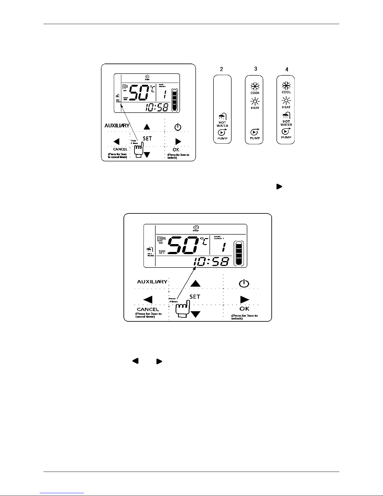
5. Setting working mode
Pressing “SET” key three times to enter the working mode setting page, then pressing the“▲” or “▼”
key to adjust , after selecting your need mode you can press “OK” key or wait seven seconds to
confirm; During setting process you can press “CANCEL” key to exit without saving. The controller
will show different working mode when it is applied to different main unit respectively.
6. Setting clock
Press the “SET” key 4 times to enter clock setting. The hour of the clock will flash, which means the
current setting is the hour of the clock, press the “▲” or “▼” to adjust, press “ ” key when finished,
and then the minute of the clock will flash, it means the current setting is the minute of the clock,
press the “▲” or “▼” to adjust, press “OK” key when finished or wait for 7 seconds to confirm. During
the setting process you can press the “CANCEL” key to exit without saving.
7. Setting water level
You can press the “SET” key 5 times to enter the water level setting, then press “▲” or “▼” to adjust
the water level, at last press “ OK ”key when finished or wait for 7 seconds to confirm. During the
setting process press the “CANCEL” key to exit without saving. The setting value is 50%, 75%
or100%. You can press “ ” or “ ” key under main page to check the water level which has been
set.
Page 41

MCAC-RTSM-2013-12 Midea High-temperature Direct-heating Heat Pump Water Heater Technical Manual
41
8. Auxiliary operation
1) Electric auxiliary heating
This function allows running the electric auxiliary heating of main unit manually.
Operation method: press “AUXILIARY” key once to enter this function“ ” icon will flash, and then
press “OK” key to confirm.
2) Cycle heating
Cycle heating function makes the direct heating water heater to run the cycle heating function.
Operation method: Press “AUXILIARY” key twice to enter this function “ ” icon will flash, press
“OK” key to confirm.
Page 42

MCAC-RTSM-2013-12 Midea High-temperature Direct-heating Heat Pump Water Heater Technical Manual
42
3) Water pump (reserved for future use.)
This function is used to run the main water pump in the device installing and debugging.
Operation method: when the wire controller is set to be 1, press “AUXILIARY” key 3 times to enter
this function. “ ” icon will flash and then press “OK” key to confirm.
4) Cancel auxiliary: To stop the auxiliary function, press the “AUXILIARY” key again, and then press
“CANCEL” key when the corresponding icon is flashing. Then the auxiliary function will be
cancelled.
PUMP
Page 43

MCAC-RTSM-2013-12 Midea High-temperature Direct-heating Heat Pump Water Heater Technical Manual
43
4. Water tank cleaning
To guarantee the water quality, the water tank should be washed and the initially produced hot water should
be drained away from the effluent at the bottom of the water tank.
5. Schematic Diagram of the Unit System
1. Directing water heating (thick line part)
2. De-frosting (thick line part)
Water tank
PTE
Heat exchanging
Compressor
Water tank
Heat exchanging
PTE
Compressor
Page 44

MCAC-RTSM-2013-12 Midea High-temperature Direct-heating Heat Pump Water Heater Technical Manual
44
6. Error Code Cause Analysis and the Solutions
Code
Code explanation
Cause analysis
Solution
E1
Power phase
sequence failure
Reverse-connection of the unit three-phase
supply line
Exchange the two supply lines after
power off.
One phase or two phases are not connected
well
Connect the supply line well after
power off.
E2
Communication
failure
Communication failure between the main unit
and the wire controller.
Correct connection between the main
unit and the A, B, P, Q and E lines of
the wire controller.
Communication failure between the main unit
and the wire controller, slave unit failure
P, Q and E lines correct connection
between the slave unit and the main
unit, no connection of the A and B lines.
Electromagnetic interference because
communication line is not the shielded line
Replace the communication line with
the shielded line.
E3
Outlet water
temperature sensor
failure
The water port between the sensor and the
main board is loose
Insert the port well.
Sensor damage
Replace the sensor.
E4
Water temperature
sensor in the water
tank failure (the unit
can also be start up,
but only for the
directly-heating type)
The T5 port between the sensor and the main
board is loose
Insert the port well.
Sensor damage
Replace the sensor.
E5
Condenser
temperature sensor
failure
The T3 port between the sensor and the main
board is loose
Insert the port well.
Sensor damage
Replace the sensor.
E6
Outdoor ambient
temperature sensor
failure
The T4 port between the sensor and the main
board is loose
Insert the port well.
Sensor damage
Replace the sensor.
E7
Electric-heating pipe
temperature sensor
failure
( RSJ-380/SN1-820D)
The T6 port between the sensor and the main
board is loose
Insert the port well.
Sensor damage
Replace the sensor.
Ec
Water inlet temp.
sensor error(T7
temp.)
The T7 port between the sensor and the main
board is loose
Insert the port well.
Sensor damage
Replace the sensor.
Eb
Exhaust temp.
sensor error(TP
temp.)
The Tp port between the sensor and the main
board is loose
Insert the port well.
Sensor damage
Replace the sensor.
P0
System low pressure
protection
Outdoor fan is not open
Check the motor of the fan.
The evaporator is dirty
Clean the evaporator
Leakage of refrigerant
Check the leaking place, mend by
welding, drawing out the air and add
refrigerant again.
P1
System high
pressure protection
Circulating
mode
Deficient circulating water
pump flow use
RSJ-380/SN1-820-D flow should be ≥
6 m3/h;
RSJ-200/SN1-540V-D flow should be
≥ 4 m
3
/h;
RSJ-100/N1-540V-D flow should be ≥
2 m3/h.
Circulation pipeline filter is dirty
and blocked
Clean the filter.
The water pump doesn’t work
Check the water pump
Warm water valve fault
Check the operation of the warm water
valve.
Bad bypass solenoid valve
operation and lack of water
flow PTE
Check the bypass solenoid valve.
Warm water valve
Check the operation of the warm water
valve.
Page 45

MCAC-RTSM-2013-12 Midea High-temperature Direct-heating Heat Pump Water Heater Technical Manual
45
De-frosting
mode
De-frosting solenoid
valve is not open
Check the de-frosting solenoid valve.
The four-way directional valve
cannot change the direction
Check the four-way directional valve.
P2
Current protection for
system 2
Compressor current protection before system
high pressure protection
The same as the system high
pressure protection.
P3
Current protection for
system 1
Compressor current protection before system
high pressure protection
The same as the system high
pressure protection.
P8
Protection for
excessive high outlet
water temperature
Deficient water flow, the outlet water
temperature is higher than 70℃ and maintain
for one minute
The same as the system high
pressure protection.
Pb
Anti-freezing
protection
Prevent PTE cracking by freezing in the winter
Normal protection, no need for treatment.
P4
Manual mode setting is invalid.
When there is any failure or protection, the red indicator of the wire controller will twinkling and the wire controller and the
digital pipe of the main unit control panel will display the code. The code of the slave unit should be checked and transferred to
the corresponding address on the wire controller and then be found by page down and page up.
Page 46

MCAC-RTSM-2013-12 Midea High-temperature Direct-heating Heat Pump Water Heater Technical Manual
46
7. Main control board spot check
Sequence
System operation parameters
Remarks
1st
Normal display Water out temperature
Value of T1
2nd
Pipe temperature
Value of T3
3rd
Ambient temperature
Value of T4
4th
Water tank temperature
Value of T5 (Just for main unit)
5th
Electric heating tube temperature
Value of T6
6th
Compressor discharge temperature
Value of Tp
7th
Setting water temperature
Value of Ts
8th
Circulate heat starting temperature
Value of Tr
9th
Current of compressor A
Value of IA
10th
Current of compressor B
Value of IB
11th
Opening of electric expansion valve
Value of electric expansion valve opening / 8
12th
Opening of electric water flow valve
Value of electric water flow valve opening / 32
13th
Operate mode
0: Stand by 1: Direct heating mode 2:Circulate
heating mode
14th
Fan speed
0: OFF 1: Low 2:Middle 3:High
15th
Elevation of water surface
0:Lower than S4 1: Between S4 and S3
2:Between S3 and S2 3:Between S2 and S1
4:Higher than S1
16th
The last error code or protection code
Display the latest error code or protection code.
If there is no code, display “--”
8. Failure without Code
Failure description
Cause analysis
Solution
The leakage switch is
switched off, which resulted
in the impossible of
switching in.
The input of the leakage switch is not equal to
the output.
1. Check whether the neutral line is connected
through the output end of leakage switch. The
neutral line is not allowed to couple in the unit
bypassing the leakage switch.
Connect the neutral line out from the
output end of the leakage switch.
2. The live line and neutral line in the same
power use equipment are coupled in different
output end of the leakage switch.
2. Connect the live line and neutral line in
the same power use equipment out from
the same output end of leakage switch.
Wire controller screen is
kept on initializing, and the
display of the water level
changes between the zero
grade and the fourth grade
continually.
1. Both the main unit and the slave unit of the A
and B power lines of wire controller are connected
1. Dismantle the A and B power lines of
the slave unit.
2. The address codes of the main unit and the
slave unit are set improperly (or no adjustment
is carried out, each unit is set to 0 before
delivering, and the default is the main unit).
2. The S1 on the panel of the main unit is
set to 0, and the DIP switches on the
panel of the slave units are set to 1, 2,
3…
Page 47

MCAC-RTSM-2013-12 Midea High-temperature Direct-heating Heat Pump Water Heater Technical Manual
47
9. Troubleshoot of abnormal phenomena
Not distribute to
malfunction
Phenomena
Cause
White aerosol or
globule is give out.
Make sound of “hiss”
every now and then.
Air supply motor stop automatically to defrost.
At the beginning and the end of the defrost process, sound is give out in
motor valve occur.
During the process or just after have stopped, sound like water flow occur,
which will be amplified at the first 2~3 minutes, this is caused by process
of refrigerant current or water discharge at dehumidifying operation.
Slight ”hiss” is caused by heat exchanger as temperature changes. The
sound give out because of heat expands and cold contracts of heat
exchanger.
During the beginning or just after have stopped, sound like clock occur,
which is caused by electric expanding valve operation.
Please check
that again
Stop operation or drive up
automatically
Detect the timer whether be given wrong operation.
Detect anti-freezing mode is opened.
No operate
Whether the power is cut.
Whether the manual power supply switch is off.
Whether fuse is broken.
Whether the protection device works.(Operation lamp is lightened.)
Whether it is the time set.(Operation lamp is lightened.)
Inefficient heating
Whether the inlet and outlet of boiler units is blocked.
 Loading...