

Page 1
MDV 2
2nd Generation ALL IN ONE Type Heat Pump Water Heater Technical Manual
nd
Generation ALL IN ONE Type
Heat Pump Water Heater
Technical Manual
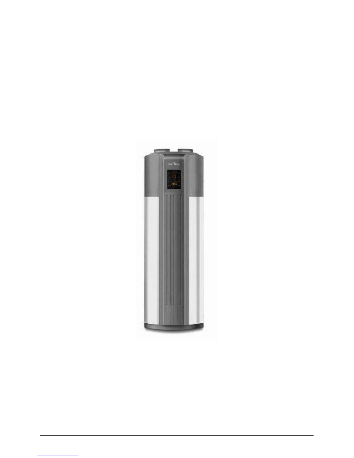
Applicable Models:
RSJ-35/300RDN3-B
1
Page 2

2nd Generation ALL IN ONE Type Heat Pump Water Heater Technical Manual
MDV reserves the right to discontinue, or change at any time, specifications or designs without notices and
without incurring obligations.
2
Page 3

2nd Generation ALL IN ONE Type Heat Pump Water Heater Technical Manual
Contents
Part 1 General Information ........................................................................5
1. Measurements....................................................................................................... 6
2. External Appearance............................................................................................ 6
3. Nomenclature........................................................................................................ 7
4. Features................................................................................................................. 8
Part 2 Outdoor Units.................................................................................10
1. Specifications......................................................................................................11
2. Operation range.................................................................................................. 17
3. Capacity&COP table........................................................................................... 17
4. Dimensions .........................................................................................................17
5. Service Space ..................................................................................................... 18
6. Wiring Diagrams................................................................................................. 18
7. Piping Diagrams ................................................................................................. 20
8. Duct connection.................................................................................................. 17
9. Exploded View .................................................................................................... 22
Part 3 Installation......................................................................................25
1. Precautions......................................................................................................... 26
2. Installation information...................................................................................... 27
3. Unit Appearance and Composition................................................................... 28
4. Accessories......................................................................................................... 29
5. Inspecting and Handling the Unit ...................................................................... 29
6. Electric Wiring..................................................................................................... 29
Part 4 Trial Operation ...............................................................................31
1. Confirmation before the trial operation............................................................ 32
2. OPERATING INSTRUCTION............................................................................... 32
3. PCB explanation................................................................................................. 51
4. Maintenance........................................................................................................ 51
5. Malfunctions and Resolutions........................................................................... 53
3
Page 4

2nd Generation ALL IN ONE Type Heat Pump Water Heater Technical Manual
Part 1
General Information
1. Measurements...................................................................6
2. External Appearance........................................................6
3. Nomenclature....................................................................7
4. Features.............................................................................8
5
Page 5
2nd Generation ALL IN ONE Type Heat Pump Water Heater Technical Manual
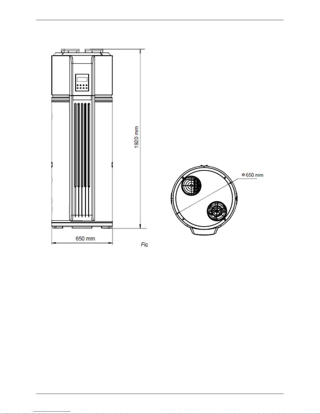
1. Measurements
Model
Dimension
(mm: OD x H)
Net weight / Gross weight
(kg)
Power Supply
RSJ-35/300RDN3-B Φ650×1920
113 /129 220~240V-1ph-50Hz
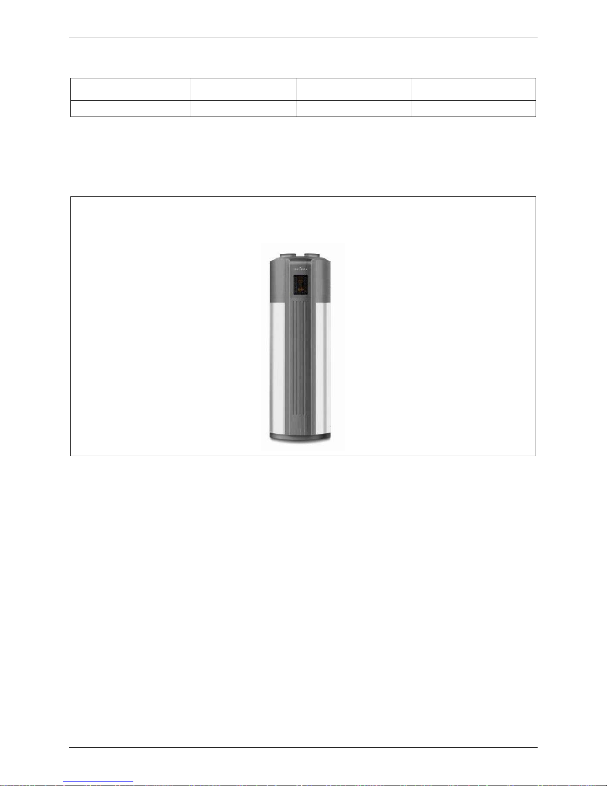
2. External Appearance
RSJ-35/300RDN3-B
6
Page 6
2nd Generation ALL IN ONE Type Heat Pump Water Heater Technical Manual
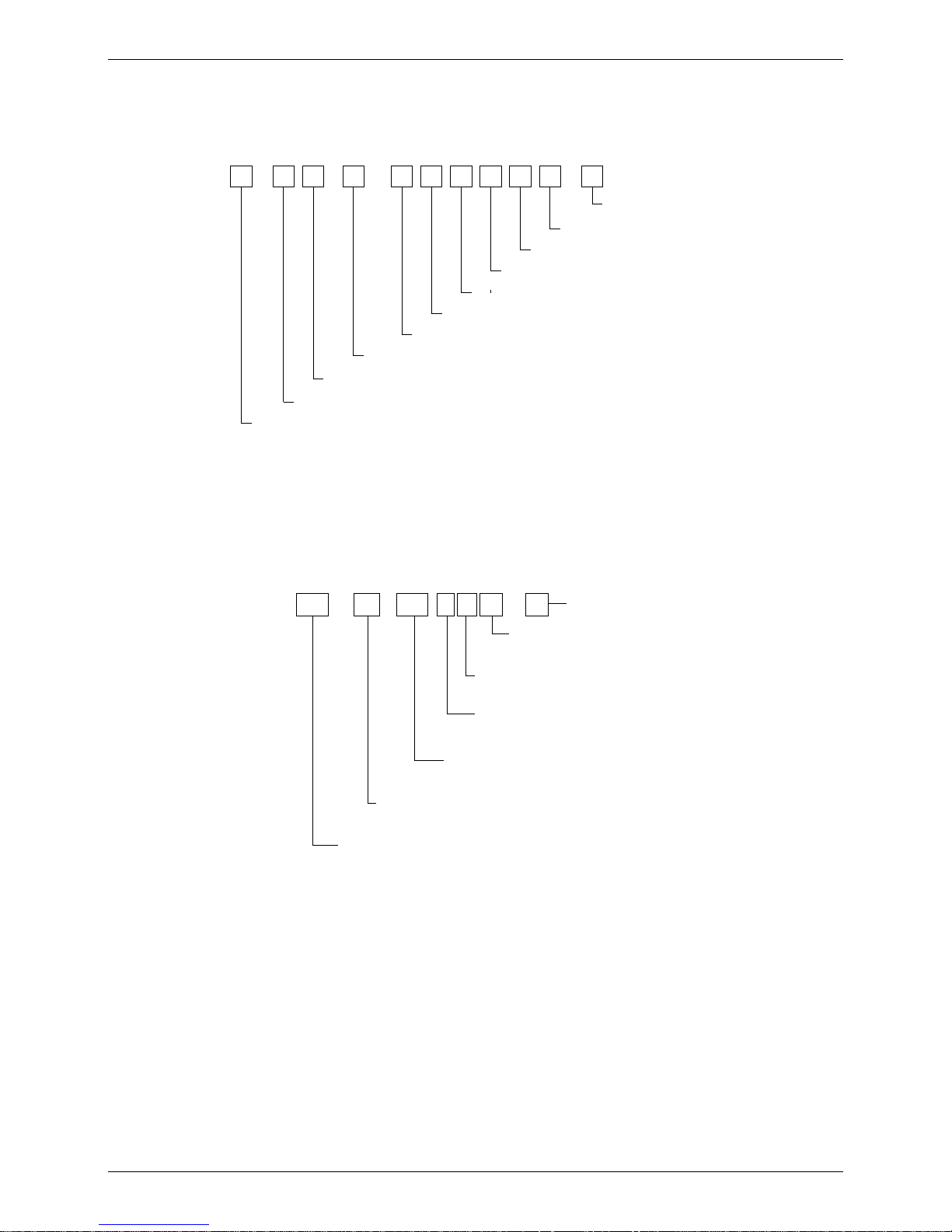
3. Nomenclature
Household Water Heating Unit
1
23
-
/
-5
Rated hot water output, unit: 100 W
6
7
8
Power supply specification code
Heating mode code
Water tank volume, unit: L
9
Other functions code
10 11
12
-
Water supply pump lift code
Refrigerant code
Design code
Installation type code
Water heating unit code
Export model code
For example:
-
B
Design code
300
Refrigerant code
Other functional code
N3
D
-
/
Water heating unit code
Rated hot water output, unit: 100 W
Water tank volume.unit:L
Heating mode code
R
35RSJ
7
Page 7
2nd Generation ALL IN ONE Type Heat Pump Water Heater Technical Manual
4. Features
4.1 Safety
a. Complete isolation between water and electricity. No
electric shock problem, more safety.
b. No fuel tubes and storage, no potential danger from oil
leakage, fire, explosion etc.
c. No cross contamination potential, the condenser coil
wrapped around the stainless steel inner tank
4.2 Max. outlet water Temperature: 60℃.
The system is adopted innovative heating methods: combined the Electric heating and Heat Pump heating
properly, made the water be heated stably and quickly.
4.3 Flexible installation achieved by long air intake/outlet duct with pressure
4.4 Built-in heat exchanger inside tank for integrating multiple energy, such as solar
energy.
8
Page 8

2nd Generation ALL IN ONE Type Heat Pump Water Heater Technical Manual
4.5 Automatic Control:
Automatic start-up and shutdown, automatic defrosting by revising refrigerant cycle. Save you much extra
operation.
4.6 High Efficiency and Energy Saving.
The unit adopts heat pump principle, which absorbs heat from outdoor air and produce heat water, thermal
efficiency can be approximately 3.6 (under the condition A15/12 W15/45)
4.7 All-the-weather Running.
Within the temperature range from -30 to 43℃, it will not be affected by night, cloudy sky,
rain even snow whether.
9
Page 9

2nd Generation ALL IN ONE Type Heat Pump Water Heater Technical Manual
Part 2
Outdoor Units
1. Specifications..................................................................11
2. Operation range..............................................................17
3. Capacity & COP table .....................................................17
4. Dimensions......................................................................17
5. Service Space..................................................................18
6. Wiring Diagrams .............................................................18
7. Piping Diagrams..............................................................20
8. Duct connection..............................................................17
9. Exploded View.................................................................22
10
Page 10
2nd Generation ALL IN ONE Type Heat Pump Water Heater Technical Manual
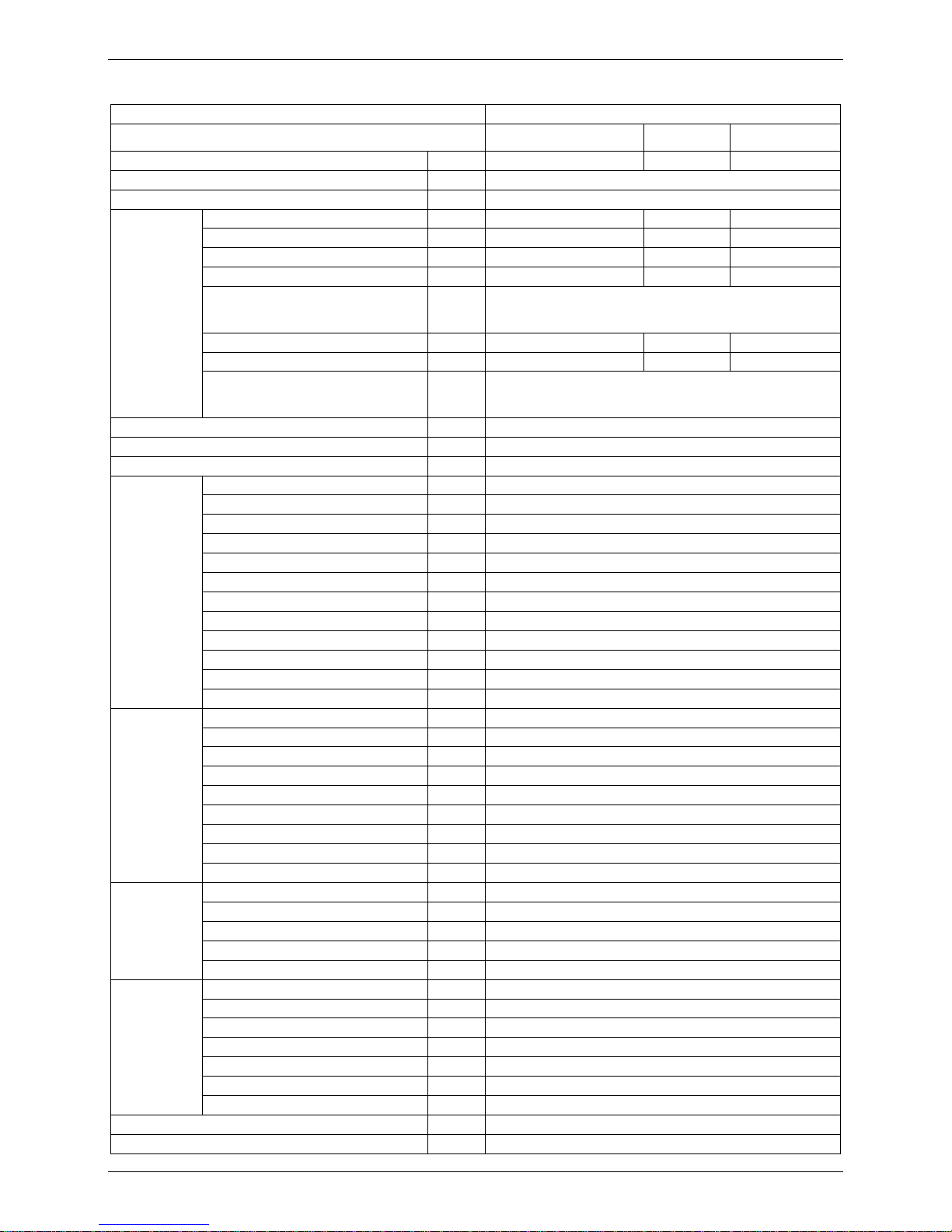
1. Specifications
Model RSJ-35/300RDN3-B
Running Models
Economy Hybrid E-heater
Running Ambient temp. ℃ -7~43 -30~43 -30~43
Power supply ph-V-Hz 220~240V-1ph-50Hz
Storage size Ltr 300
Capacity KW 3.00 3.00 3.00
Input KW 0.83 0.83 3.00
Cop W/W 3.60 3.60 1.00
Rated current A 3.00 3.00 3.00
Testing Condition
Economy: A15/12 W15/45, setting Economy Mode;
Hybrid: A15/12 W15/45, setting Hybird Mode;
E-heater: A15/12 W15/45, setting E-heater Mode;
Max. Input KW 1.50 4.30 3.00
Max. Current A 6.50 18.7 13
Water
Heating
Nonimal
Testing Condition
Economy: A 43 W60, setting Economy Mode;
Hybrid: A 10 W60, setting Hybird Mode;
E-heater: A15 W60, setting E-heater Mode;
Max. Input KW 4.3
Max. current A 18.7
Starting current A 49.0
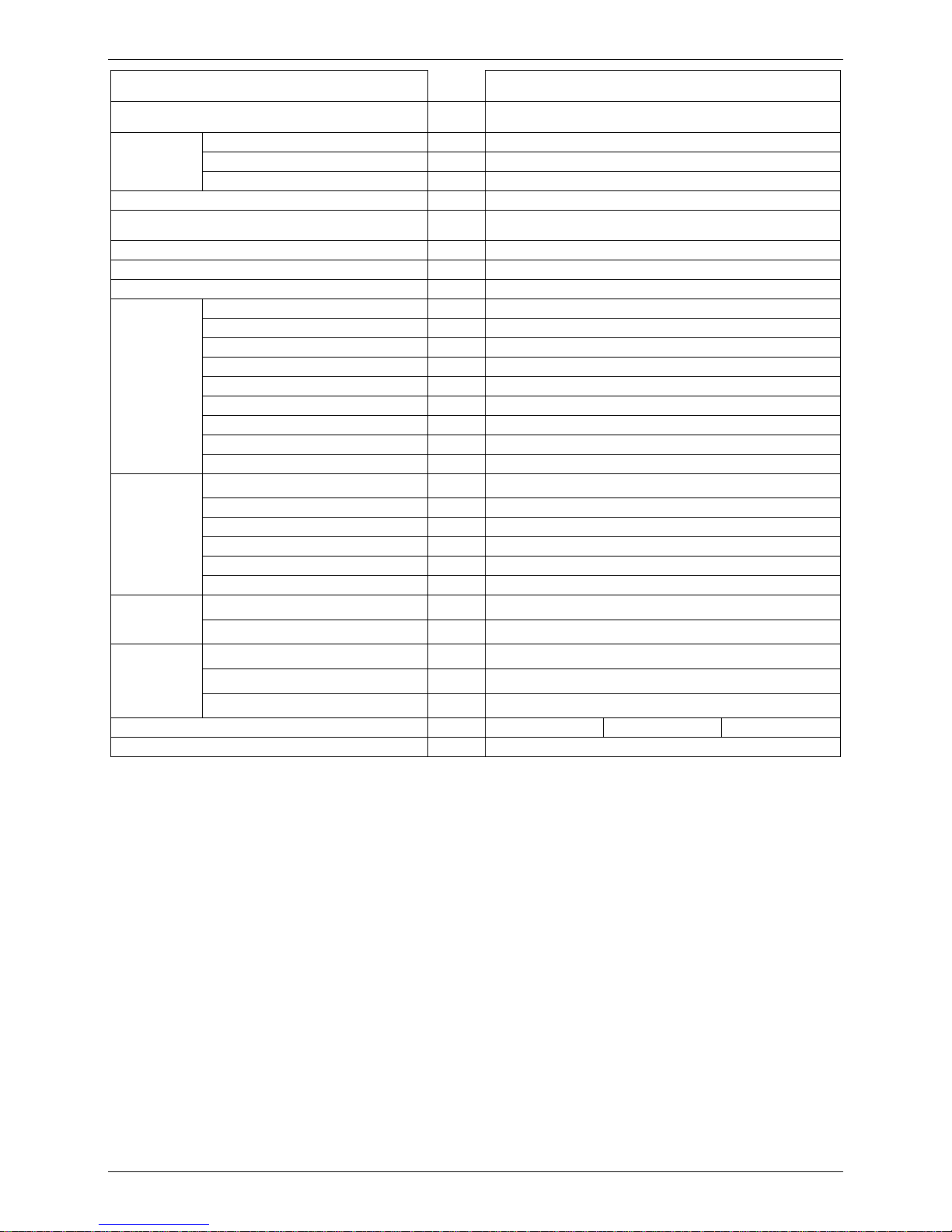
Model RB233GRDC
Type Rotary
Brand Guangzhou Mitsubishi electric
Supplier Guangzhou Mitsubishi electric
Capacity Btu/h 9500
Input W 850
Rated current(RLA) A 4.1
Locked rotor Amp(LRA) A 30
Thermal protector ℃ 115
Capacitor uF 30
Crankcase W 25
Compressor
Refrigerant oil ml 440 (HAB (NEO 32 or similar))
Model YDK30-6R
Type AC Motor
Brand Welling
Insulation class B
Safety class IPX4
Input W 68
Rated current A 0.3
Capacitor uF 2.5
outdoor fan
motor
Speed(hi/lo) r/min 620/530/465
material ASG20
Type Centrifugal type
Pressure pa 30
Diameter mm 271
outdoor fan
Height mm 130
Number of rows 3
Tube pitch(a)x row pitch(b) mm 22*19.05
Fin spacing mm 1.5
Fin type Arc hydrophile seam punching fin
Tube outer dia.and type mm Ф8.0 innergroove tube
Coil length x height 482*352
outdoor coil
Number of circuits 4
Outdoor air flow (Hi/mid/lo) m3/h 414/355/312
Noise level dB(A) 46.6
11
Page 11
2nd Generation ALL IN ONE Type Heat Pump Water Heater Technical Manual
Running Operation
Auto/Manual start up, Energy-saving, standard, Enhanced
heating type heating water
Protection Method
High-pressure protection, Over-load protection,
Temp protection, Electric leakage protection
Dimension (D*H) mm Φ650×1920
Packing (W*H*D) mm 745*2030*775
Outdoor unit
Net/Gross weight kg 113/129
Refrigerant type/Quantity Kg R134a/1.2
Design pressure
(Operating pressure Refrigerant)
MPa 3.0/1.2
Tank pressure Mpa 0.15/0.7
Tank Foaming Material/Depth(mm) polyurethane/55mm
Ambient temp ℃ -30~43
Diameter, water inlet pipe mm DN20
Diameter, water outlet pipe mm DN20
Diameter, drainage pipe mm DN20
Diameter, PT valve joint mm DN20
PT valce Brand Watts (active condition 99℃ or 1.0Mpa )
Rated pressure MPa 1.2
Max. Operation pressure MPa 0.7
Water outlet Temp ℃ (default) 55℃, 38℃~60℃
water
pipeline
Heat exchanger Copper tube wrapped around outside of tank
Diameter, water inlet pipe
mm
DN20
Diameter, water outlet pipe mm DN20
Heat exchanger Surface heat exchanger; Stailess steel SUS316L
heat exchanger tupe Dim.*Length mm Φ22*10000
heat exchanger area m2 0.7
Solar heat
exchanger
pipeline
Max.pressure MPa 0.7
Power wiring
mm2
4
Connection
wiring
Signal wiring
mm2
0.75
Fresh Air Diameter
mm
190.0
static pressure
Pa
30.0
Fresh air
Max Length
m
10.0
Hot Water Yield m3/h 0.075 0.075 0.064
Electric Heater kW 3.0
Remark:
1. The test conditions: outdoor temp. 15/12℃(DB/WB), inlet water temp. 15℃, outlet water temp. 45℃.
2. The operation range:-30℃-48℃, heat pump operation range: -7℃-43℃
3. The specification may be changed for product improvement, please refer to the nameplate.
12
Page 12
2nd Generation ALL IN ONE Type Heat Pump Water Heater Technical Manual
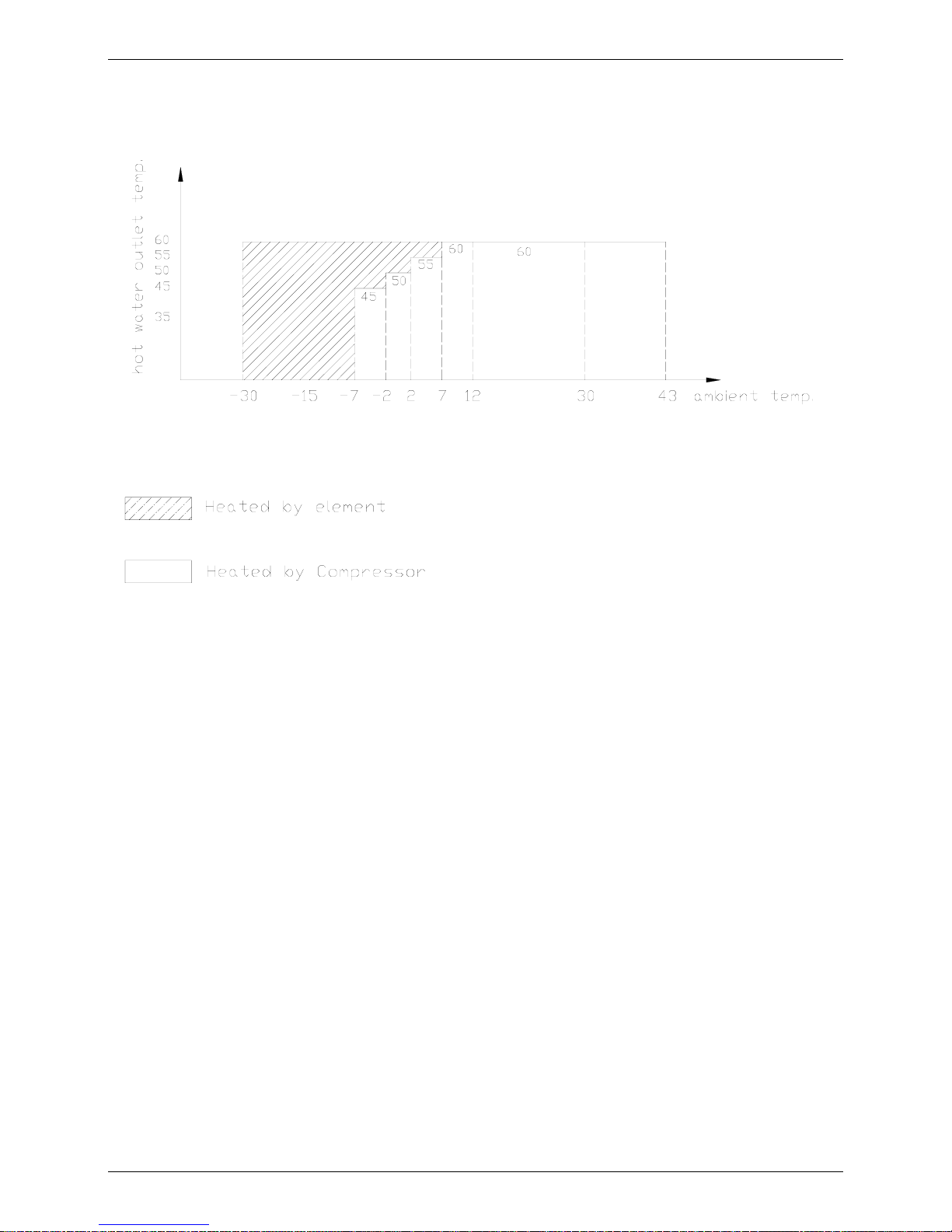
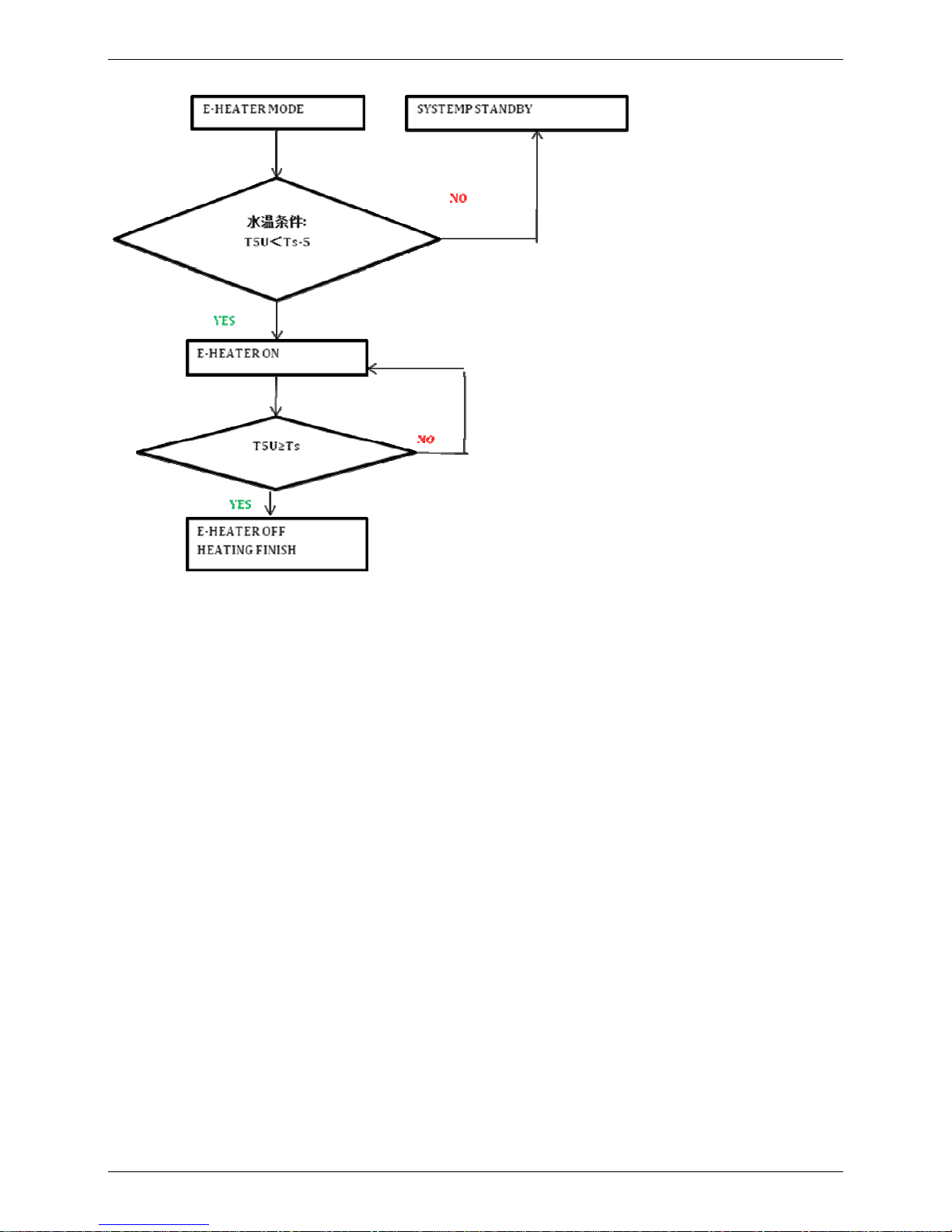
2. Operation range
Mode explanation: there are 3 operation MODE: ECONOMY, HYBRID and E-HEATER
ECONOMY MODE: Water firstly is heated by compressor, if can’t get target temp when ambient temp. too low or too high
(limitation figure is shown above), element will start as a secondary heat resource.
Hybrid mode: In case of massive hot water consumption, compressor & element will start at the same time.
E-HEATER MODE: Water is only heated by element;
13
Page 13
2nd Generation ALL IN ONE Type Heat Pump Water Heater Technical Manual
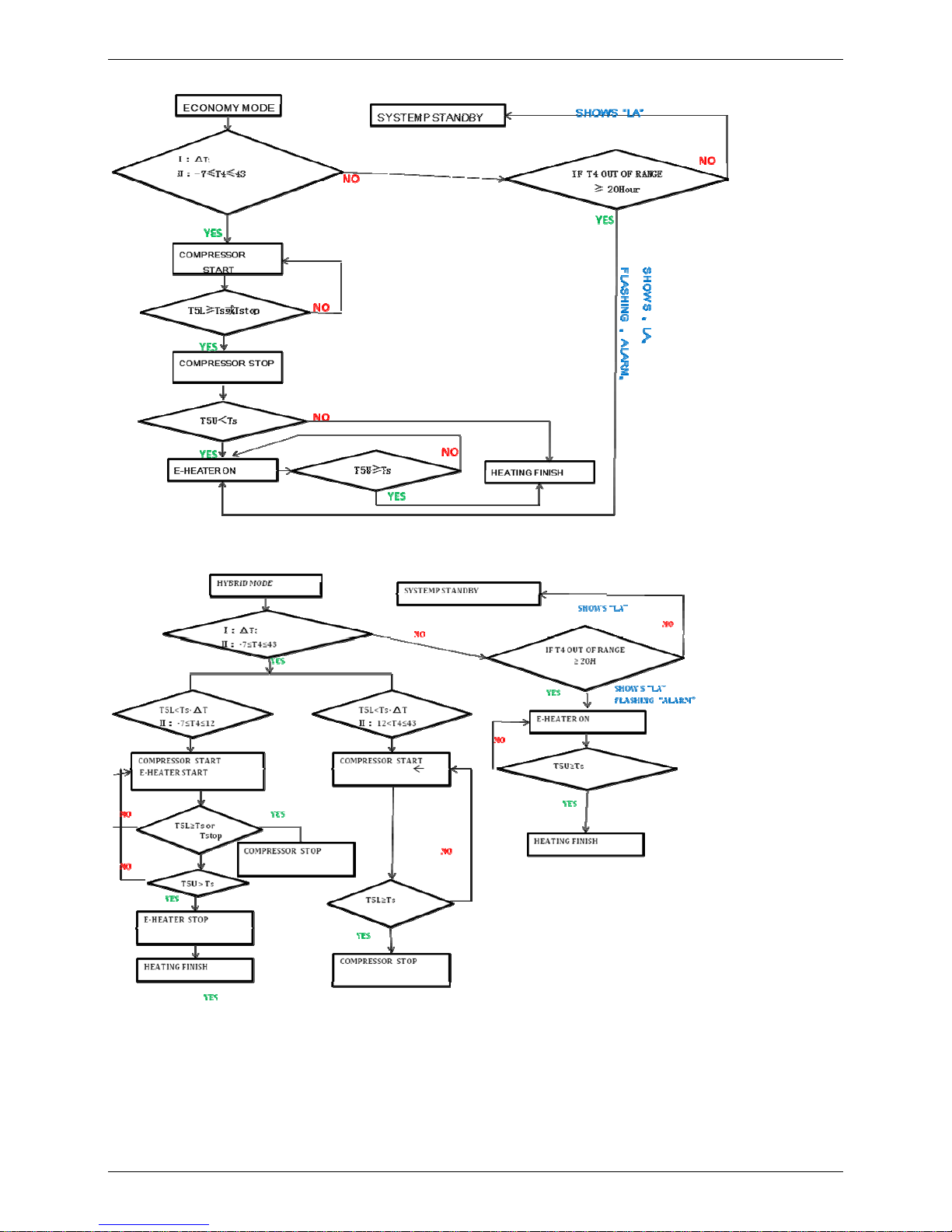
ECONOMY MODE:
Hybrid mode:
14
Page 14
2nd Generation ALL IN ONE Type Heat Pump Water Heater Technical Manual
E-HEATER MODE:
15
Page 15
2nd Generation ALL IN ONE Type Heat Pump Water Heater Technical Manual
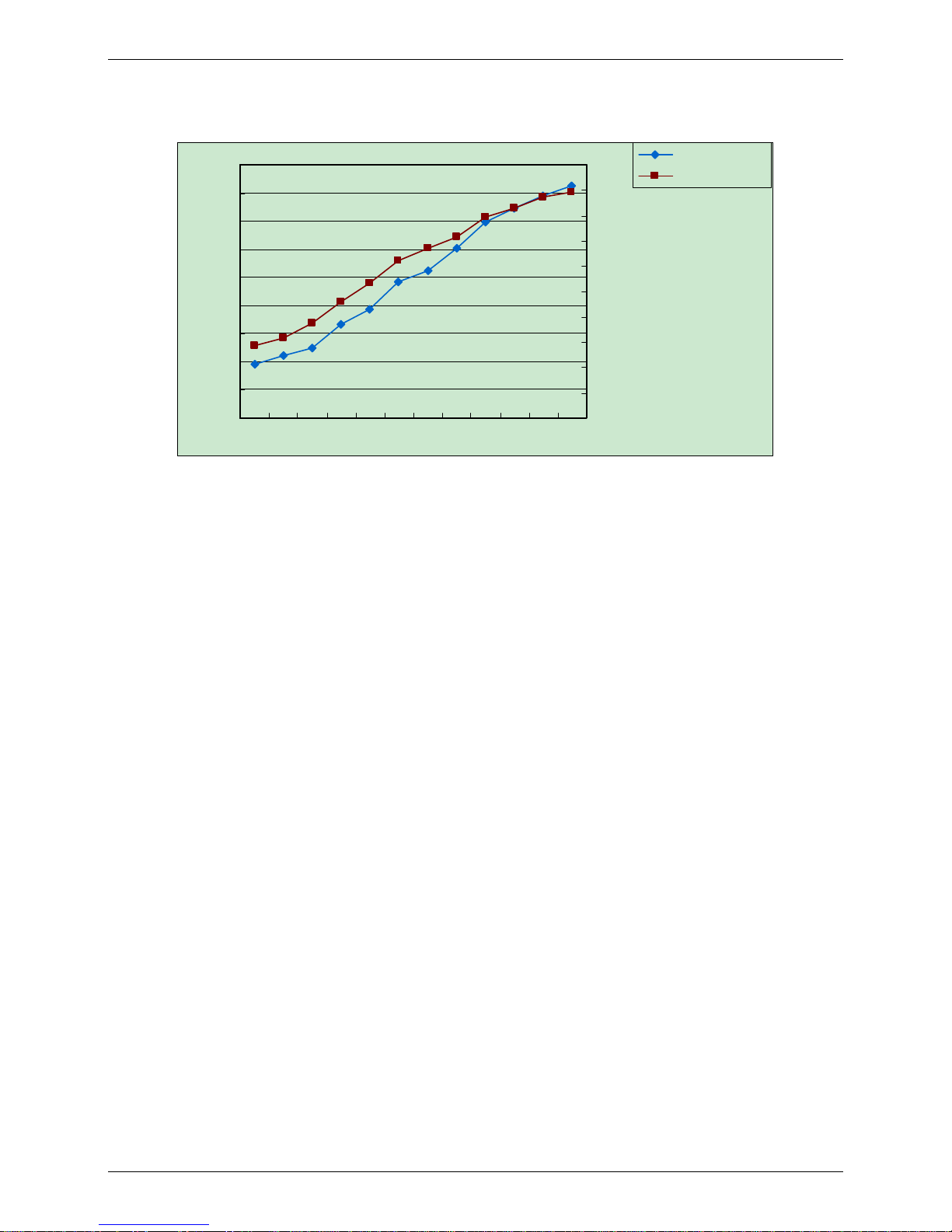
3.
Capacity & COP table
500
1000
1500
2000
2500
3000
3500
4000
4500
5000
-7 -2 2 7 10 15 20 25 30 35 40 43
0.5
1
1.5
2
2.5
3
3.5
4
4.5
5
5.5
Capa. (W)
COP (W/W)
Ambient temp(℃)
Remark:
Water inlet temp. 15℃, Water outlet temp. 45℃
16
Page 16
2nd Generation ALL IN ONE Type Heat Pump Water Heater Technical Manual
4. Dimensions
17
Page 17
2nd Generation ALL IN ONE Type Heat Pump Water Heater Technical Manual
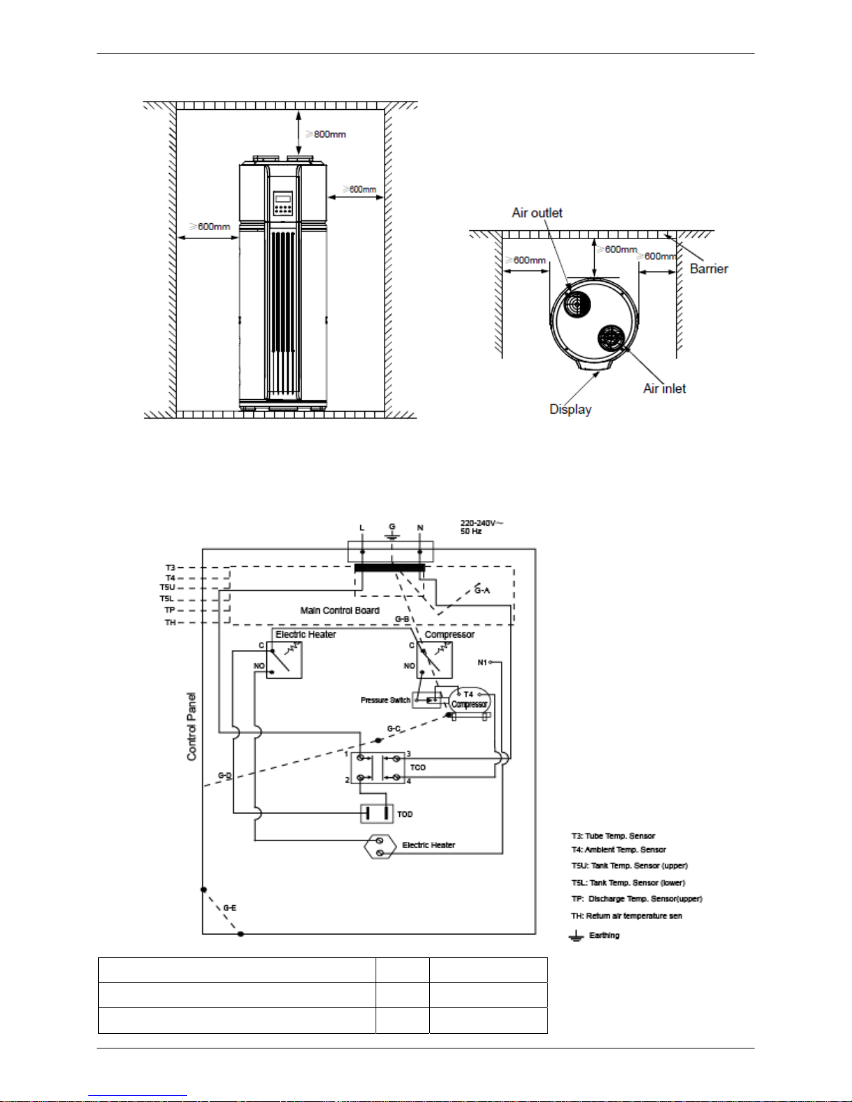
5. Service Space
6. Wiring Diagrams
manometer (High Pressure Switch)
1 202301800820
Discharge temp sensor ass'y (Tp)
1 202301300130
room temp sensor ass'y (T4)
1 202301300196
18
Page 18

2nd Generation ALL IN ONE Type Heat Pump Water Heater Technical Manual
Temp.sensor ass'y (T3)
1 202301300437
Temperature sensor (Th)
1 202301300303
senor ass'y, for the pipe (T5L)
1 202301300485
senor ass'y, for the pipe (T5Up)
1 202301300486
Relay of Elment & Compressor
2 202300800003
TCO(turn off temp. 85±3°C,manually recovery)
1 202301610028
TOD Auto Recovery, turn off temp.78±3°C,Recovery
temp 68±3°C。
1 202301600046
19
Page 19

2nd Generation ALL IN ONE Type Heat Pump Water Heater Technical Manual
7. Piping Diagrams
20
Page 20

2nd Generation ALL IN ONE Type Heat Pump Water Heater Technical Manual
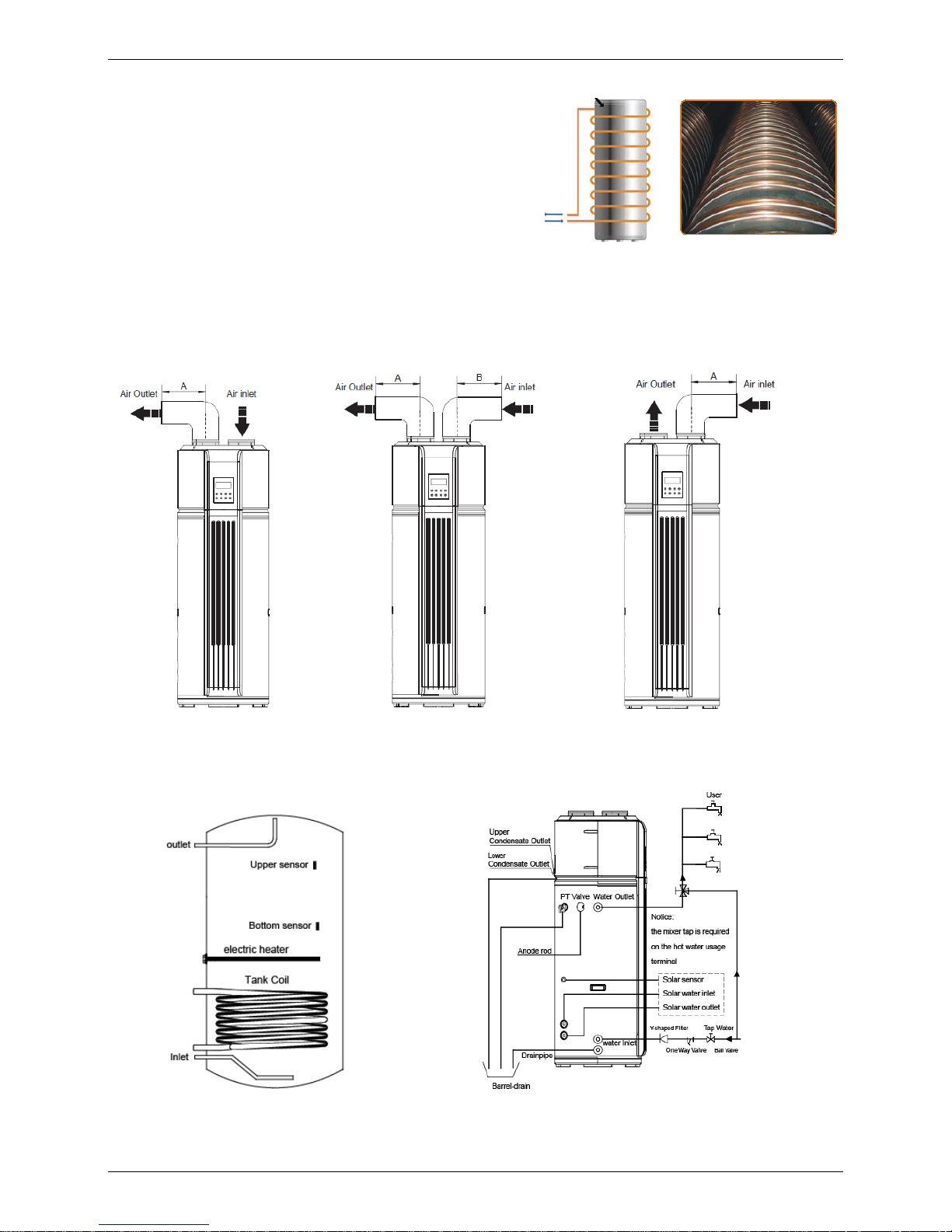
8. Duct connection
A: Air inlet & outlet without canvas B: Only air outlet with canvas, A≤10m
When there is stable heat source in room in winter
C: Air inlet & outlet with canvas, A+B≤10m D: Only air inlet with canvas A≤10m
Charge fresh air from ambient in summer
21
Page 21

2nd Generation ALL IN ONE Type Heat Pump Water Heater Technical Manual
9. Exploded View
22
Page 22

2nd Generation ALL IN ONE Type Heat Pump Water Heater Technical Manual
No. Part Name
Quantity
No. Part Name
1
airout ring
2 18
decorating board
2
air filter
1 19
cover, upper heating element
3
filter
2 20
Deck magnet
4
plastic hourse
1 21
Magnet clip
5
top
1 22
Magnet cover
6
magnesium stick plug
1 23
four-way valve
7
cover, wire-connceting box
1 23.1
Pipe joint
8
asynchronism motor
1 23.2
manometer (High Pressure Switch)
9
Display board
1 23.3
4-way valve
10
Display board ass'y
1 23.4
Solenoid
11
centrifugal fan
1 24
Electronic Expansion Valve ass'y
12
cover, display
1 24.1
EEV solenoid
13
electric control box
1 24.2
Solenoid valve winding
14
forming
1 24.3
Electronic Expansion Valve
14.1
forming plug
1 24.4
Solenoid valve
14.2
Froth plug
2 25
compressor
14.3
TCO(turn off temp. 85±3°C,
manually recovery)
1 26
Discharge temp sensor ass'y (Tp)
14.4
magnesium stick
1 27
room temp sensor ass'y (T4)
14.5
TOD Auto Recovery, turn off
temp.78±3°C,Recovery temp 68
±3°C。
1 28
Temp.sensor ass'y (T3)
14.6
Stator of temp. sensor
1 29
Temperature sensor (Th)
14.7
heating element
1 30
senor ass'y, for the pipe (T5L)
14.8
Sealed ring
1 31
senor ass'y, for the pipe (T5Up)
14.9
Seal Stopper
4 32
Compressor electric heater
14.10
Drain stop up
1 33
evaperator ass'y
14.11
lower cover, for the tank
1 33.1
evaperator
14.12
PT velve loop
7 33.2
evaperator output pipe ass'y
14.13
handle for the tank
2 33.3
evaperator input pipe ass'y
14.14
PT valve
1 34
wire connecting box
15
magnetic holder
1 34.1
holder
23
Page 23

2nd Generation ALL IN ONE Type Heat Pump Water Heater Technical Manual
16
electric control board ass'y
1 34.2
Wire joint, 3p
16.1
electric control board
jointing
1 35
front snail shell
16.2
Compressor capacitor
1 36
compressor connector
16.3
main control board ass'y
1 37
Platen
16.4
transformer for power supply
1 38
back snail shell
16.5
Motor capacitor
1 39
Drainage bend
16.6
Wire joint
4 40
upper plastic house
16.7
Relay of Elment & Compressor
2 41
filter
17
holder for electric control
board ass'y
1
24
Page 24

2nd Generation ALL IN ONE Type Heat Pump Water Heater Technical Manual
Part 3
Installation
1. Precautions .....................................................................26
2. Installation information..................................................27
3. Unit Appearance and Composition...............................28
4. Accessories.....................................................................29
5. Inspecting and Handling the Unit..................................29
6. Electric Wiring.................................................................29
25
Page 25

2nd Generation ALL IN ONE Type Heat Pump Water Heater Technical Manual
1. Precautions
To prevent injury to the user or other people and property damage, the following instructions must be
followed. Incorrect operation due to ignoring of instructions may cause harm or damage.
The safety precautions listed here are divided into two categories. In either case, important safety
instructions are listed to which close attention must be paid.
WARNING
Failure to observe a warning may result in death.
CAUTION
Failure to observe a caution may result in injury or damage to the equipment.
WARNING
■ The water heating unit must be earthed effectively.
■ A creepage breaker must be installed near the power supply.
■ Ask your supplier for installation of the air source heat pump water heating units. Incomplete installation
performed by yourself may result in water leakage, electric shock, or fire.
■ Ask your supplier for the repair and maintenance. Incomplete repair and maintenance may result in
water leakage, electric shock or fire.
■ In order to avoid electric shock, fire or injury, if any abnormality is detected, such as smell of fire, turn off
the power supply and call your supplier for instructions.
■ Never replace a fuse with that of wrong rated current or other wires when a fuse blows out. Use of
wrong wire or copper wire may cause the unit to break down or a fire.
■ Do not insert fingers, rods or other objects into the air inlet or outlet. When the fan is rotating at high
speed, it will cause injury.
■ Never use a flammable spray such as hair spray, lacquer paint near the unit. It may cause a fire.
■ Never touch the air outlet or the horizontal blades while the swing flap is in operation. Fingers may
become caught or the unit may break down.
■ Never put any objects into the air inlet or outlet. Objects touching the fan of high speed can be
dangerous.
■ Do not dispose this product as unsorted municipal waste. Collection of such waste separately for
special treatment is necessary.
■ The appliance shall be installed in accordance with national wiring regulations.
CAUTION
■ The ground pole of socket must be grounded, and the rated current should be more than 10A. Make
sure that socket and attaching plug are dry always and have a good connection.
Method: Turn on power supply, run the unit for half a hour, then turn it off and check if the attaching plug
is hard. If it’s hard (more than 50℃), please change it with a new and eligible one, or it may result in an
electric shock or fire.
■ Do not use the air-source water heater for other purposes.
■ Before cleaning, be sure to stop the operation and turn the breaker off or pull out the power cord.
Otherwise, an electric shock and injury may be caused.
■ In order to avoid injury, do not remove the fan guard on the outdoor unit.
■ Do not operate the air-source water heater with a wet hand. An electric shock may be caused.
■ In the place and the wall where water may be spattered, the installation height must be more than 1.8m.
■ At the water inlet, the One Way valve must be installed.
26
Page 26

2nd Generation ALL IN ONE Type Heat Pump Water Heater Technical Manual
■ It’s normal if some water drips from the hole of PT valve in operation. But, if the water is in a great
amount, call your supplier for instructions.
■ After a long use, check the unit stand and fittings. If damaged, the unit may fall and result in injury.
■ Arrange the drain hose to ensure smooth drainpipe. Incomplete drainpipe may cause wetting of the
building, furniture etc.
■ Never touch the internal parts of the controller.
■ Do not remove the front panel. Some parts inside are dangerous to touch, and a machine malfunction
may be caused.
■ Never expose babies, plants or animals directly to the air flow. Adverse influence to babies, animals and
plants may be resulted.
2. Installation information
■ Enough space is installation and maintenance shall be preserved.
■ The air inlet and outlet should be free from obstacles and strong wind.
■ The bearing surface should be flat, able to bear weight of the unit and suitable for installing the unit
horizontally without increasing noise or vibration.
■ The operation noise and air flow expelled shall not affect neighbors.
■ No flammable gas is leaked nearby.
■ It is convenient for piping and wiring.
CAUTION
■ Installing the equipment in any of the following places may lead to malfunction of the equipment (if it is
inevitable, consult the supplier):
1) The site contains mineral oils such as cutting lubricant.
2) Seaside where the air contains much salt.
3) Hot spring area where corrosive gases exist, e.g., sulfide gas.
4) Factories where the power voltage fluctuates seriously.
5) Inside a car or cabin.
6) Place like kitchen where oil permeates.
7) Place where strong electromagnetic waves exist.
8) Place where flammable gases or materials exist.
9) Place where acid or alkali gases evaporate.
10) Other special environments.
■ Precautions before installation
1) Decide the correct way of conveying the equipment.
2) Try to transport this equipment with the original package.
3) If the unit has to be installed on a metal part of the building, electric insulation must be installed, and the
installation must meet the relevant technical standards for electric devices.
■ Installation space
Before installing the unit, reserve the space of maintenance .
WARNING
■ Ask your supplier to install the air source heat pump water heating units. Incomplete installation
performed by yourself may result in a water leakage, electric shock, or fire.
■ The place without direct sunlight and other heat supplies. If there’s no way to avoid these, please install
a covering.
27
Page 27

2nd Generation ALL IN ONE Type Heat Pump Water Heater Technical Manual
■ The unit must be securely fixed, or else, noise and shaking will be resulted.
■ Make sure that there’s no remora around the unit.
■ In the place where there is strong wind like seashore, fix the unit in the location protected from the wind.
■ Carry the unit onto the site
1) In order to avoid scratch or deformation of the unit surface, apply guard boards to the contacting
surface.
2) No contact of fingers and other things with the vanes.
3) Don’t incline the unit more than 45° in moving, and keep it vertical when installing.
■ Install the unit.
1) The circulating air for every unit should be more than 700m3/h.
2) Make sure there is enough Installation space.
3) Outline dimensional drawing
3. Unit Appearance and Composition
28
Page 28

2nd Generation ALL IN ONE Type Heat Pump Water Heater Technical Manual
4. Accessories
Check whether the following assemblies are complete.
Name Quantity Note Purpose
Installation& Operation Manual 1 —— Installation and Operation instruction
Y-sharp Filter 1 —— Inlet water filter
Drain Pipe for Condensate water 2 —— For condensed water discharge use
One Way Valve 1 —— To prevent water from flowing back
Wired Controller (optional) —— —— To control and monitor the unit status
5. Inspecting and Handling the Unit
After delivery, the package should be checked and any damage should be reported immediately to the
carrier claims agent.
When handling the unit, take into account the following:
1.
Fragile, handle the unit with care.
Keep the unit upright in order to avoid compressor damage.
2. Choose before hand the path along which the unit is to be brought in.
3. Move this unit with original package.
4. When lifting the unit , always use protectors to prevent belt damage and pay attention to the balance of
the unit’s gravity.
6. Electric Wiring
6.1 Attention
● The water heater should powered separately and the power voltage should be in line with rated voltage..
● The power supply circuit of the water heater should be earthed, the power cord should be connected
with the external earthing line in reliable state and all the external earthing cables are effective.
● The construction of the wiring should be carried out by professionals in accordance with the circuit diagram.
● Set up leakage protection devices in accordance with the requirements of the relevant national
technical standards.
● The power cord and the signal line should be laid neatly without cross-interfere and should not contact
with the connecting pipe and the valves.
● The unit is not equipped with power cord. Please refer to the prescribed power specification for
selecting the power cord and cross-connection between two lines are not allowed.
● Check whether all the connections are correct before powering the unit.
6.2 Power specification
4
29
Page 29

2nd Generation ALL IN ONE Type Heat Pump Water Heater Technical Manual
6.3 Power Supply Wiring .
A. Power Supply Schematic Diagram
Earthing
Water Heating Unit
Manual Switch
Power
supply
Creepage Breaker
Warming:
Although there is a leakage protector in the electric control box of the unit, for the security reason, it is
required that a leakage protection equipped cable and Earthing should be applied for the unit according to
the requirement on the above diagram.
B. Cable Diameter Selection
The power supply wiring refers to the wiring to the main line (a) of junction box and the wiring (b) to the
power supply equipment. Please select the cable diameter according to the following methods
1) Diameter of the main line (a):
Get from the power supply specification table according to the sum of horsepower of the unit.
2) Diameter of the wiring from the junction box to the power supply equipment:
When the water heaters are less than 5 sets, the diameter the wiring from the junction box to the power
supply equipment should be the same as the main line (a); when the water heaters are more than 6 sets, the
power supply equipment should have two sets of electric control box and the diameter should be get from
the power supply specification table according to the sum of horsepower of the units connected by the
electric control box.
30
Page 30

2nd Generation ALL IN ONE Type Heat Pump Water Heater Technical Manual
Part 4
Trial Operation
1. Confirmation Before the Trial Operation....................327
2. Operating Instruction .....................................................32
3. PCB explanation .............................................................51
4. Maintenance....................................................................51
5. Malfunctions and Resolutions.......................................53
31
Page 31

2nd Generation ALL IN ONE Type Heat Pump Water Heater Technical Manual
1. Confirmation Before the Trial Operation
1.1 All the installation is complete.
1.2 Water heater is installed correctly.
1.3 The pipelines and wiring are correct.
1.4 The accessories are installed correctly.
1.5 The drainage is smooth.
1.6 The thermal insulation is sound.
1.7 The earthing wire is connected correctly.
1.8 The power voltage is consistent with the rated voltage of the heater.
1.9 No obstacle at the air inlet and outlet of the unit.
1.10 The leakage protector can work effectively.
2. Operating Instruction
2.1 Instruction
2.1.1 Before using this unit, please follow the steps below.
Water Affusion: If the unit is used for the first time or used again after emptying the tank, please make sure
that the tank is full of water before turning on the power. Method: see figure 2.1.1
Hot water outlet
Close
Water out
When water flows out from the water
outlet, the tank is full.
Turn o
ff the hot
water outlet valve and water a
ffusion
is finished.
Hot water outlet
Cool water inlet
Open
Open the cool water inlet and
hot water outlet
Open
Water Affusion
NOTE:
1. The Ball Valve at water inlet should be open when the unit is in operation.
2. Operation without water in water tank may result in damage of auxiliary e-heater. Due to such damage, the supplier is not
responsible for the quality issue.
3. Over 50℃ may result in serious burn or so caused death. Special care should be paid to the children, the disabled and
the old in case of water burn.
32
Page 32

2nd Generation ALL IN ONE Type Heat Pump Water Heater Technical Manual
2.1.2 After powered on, the display lights up. Users can operate the unit through the buttons under the
display for different modes. Emptying: If the unit needs cleaning, moving etc, the tank should be
emptied. Method: See Figure 2.1.2
Close
Open
Drainpipe
Open
Cool water inlet
Hot water outlet
Close the cool water inlet, open the hot
drainpipe.
water outlet and open the nut of
After emptying, please close the nut
of drainpipe
Close
Drainpipe
Emptying
NOTE: The outlet water temp. may be very high when emptying, beware of your body for burns.
2.2 Operation
2.2.1 Control Panel Explanation
Display
Operation
HYBRID MODE
OUTLET TEMP
ECONOMY MODE
HIGH TEMP
FILL WA TER
ALARM
LOCK
TIME OFF
TIME ON
TIMER
CONFLICT
TEMP-SET
E-HEATER MODE
33
Page 33

2nd Generation ALL IN ONE Type Heat Pump Water Heater Technical Manual
2.2.2 Display Explanation
TEMP-SET
16
15
14
13 12 11 10 9
8
7
6
5
4321
HYBRID MODE
OUTLET TEMP
ECONOMY MODE
HIGH TEMP
FILL WATER
ALARM
LOCK
TIME OFF
TIME ON
TIMER
CONFLICT
E-HEATER MODE
Number Explanation Number Explanation
1
HIGH TEMP indicator. When the setting temp.
exceeds 50℃, it lights up to remind you that the
outlet temp. is too high for direct spray.
9
OUTLET TEMP indicator. It displays water temp.
of the upper part of the tank, which can be used.
It always lights.
2
FILL WATER indicator. When the power supply is
turned on, it lights up to remind you to re-affuse
water.
10
TIMER CONFLICT indicator. When the temp
you set through Wired Controller conflicts with
that through User Interface, it lights up.
3
ALARM indicator: It will flashing at the malfunction
or protection time.
11
TIME OFF indicator: It will light up when timing
off mode is set, blanks when screen
protection.et, blanks when screen protection.
4
TEMP-SET indicator: Show the setting
temperature and blank when screen protection.
Codes are show at the
malfunction or protection time
12
TIME ON indicator: It will light up when timing
on mode is set, blanks when screen
protection.et, blanks when screen protection.
5
LOCK indicator. When the UI is locked, it always
lights.
13
CLOCK indicator. It displays present time, it will
blanks when screen protection
6
Water temp. indicator. When the actual water
temp. exceeds 60℃, it lights up.
14
E-HEATER MODE indicator. When user sets the
E-heating Mode, it lights up.
7
Water temp. indicator. When the actual water
temp.exceeds 50℃, it lights up.
15
HYBRID MODE indicator. When user sets the
Hybrid Mode, it lights up.
8
Water temp. indicator. When the actual water
temp. exceeds 40℃ it lights up.
16
ECONOMY MODE indicator. When user set the
Economy Mode, it lights up.
2.2.3 Operation
OFF timer
used to set the
DOWN ke
y,
used to abate
time or temp.
UP key,
used to add
time or temp.
MODE ke
y,
used to set
di
fferent modes
CANCE
L key,
used to canel
timer and lock
CLOCK ke
y,
used to set
time.
ON\OFF ke
y,
used to turn the
unit on or o
ff
34
Page 34

2nd Generation ALL IN ONE Type Heat Pump Water Heater Technical Manual
2.2.4 Operation Instruction
2.2.4.1 Preparation before running the unit.
a) When you run the unit for the first time, all the indicators on the UI will light for 3 second, and the
buzzer will “didi” ring twice at the same time, and then, display the fiducially web page. After no
operation for 1 minute, all indicators will go out automatically except Water fill indicator flashing and
Clock indicator lighting. Buzzer will “di” ring when you press it.
b) When the tank is full, please press the ON\OFF key, the Water fill indicator will stop flashing and
you can continue to function other settings. When all settings finished, please press the ON\OFF
key again and the Water fill indicator will go out. And then run the unit.
c) When the unit is running, if there is no operation or malfunction for 20s, the backlight of the display
will go out automatically except Clock indicator and Water fill indicator. If there no operation for
1min, the unit will lock automatically, but the lock indirator would be right all time.
2.2.4.2 Lock and Unlock
In order to prevent wrong operation, a special lock function has been designed. If there is no operation for
1min, the unit will be locked automatically, and display the lock sign (Lock indicator lights up).When the unit
is locked, no keys can be operated.
Press the CANCEL key 3s, the unit will
be unlocked, the LOCK sign disappears
and all keys can be operated normally
2.2.4.3 Clock Setting
The clock is for a 24-hour system and the initial time is 00:00. To make a better use of this unit, it is
recommended to set the time for accurate local time. Every time powered off, the clock will be reset to the
initial time 00:00.Method for time set
35
Page 35

2nd Generation ALL IN ONE Type Heat Pump Water Heater Technical Manual
Stop operation for about 10s, flashing will
stop and clock set is successful.
Press the “UP” and “
DOWN
” key, you can
adjust the hour.
Press the CLOCK key again, the minute
digit stops flashing while the hour digit
starts.
Press the “UP” and “
DOWN
” key, you can
adjust the minute.
Press the CLOCK key, the minute digit of
the clock on the display starts flashing
slowly.
36
Page 36

2nd Generation ALL IN ONE Type Heat Pump Water Heater Technical Manual
2.2.4.4 Mode Selection
a) The unit is enhanced with three operation modes, Economy Mode, Hybrid Mode and E-heater
Mode.
b) Economy Mode: The unit heats water only by compressor drive according to heat-pump principle.
Used when the ambient temp. is high.
c) Hybrid Mode: The unit heats water not only by compressor drive but also by electric heater. Used
when the ambient temp. is low or large amount of hot water is needed.
d) E-heater Mode: The unit heats water only by electric heater. Used when the ambient temp. is very
low.
e) By default, the unit operates in Hybrid Mode.
Change:
Press the
MODE
key, operation mode will
be
shifted
among the three modes in a
cycle, meanwhile the corresponding
indicator on the display will light up.
2.2.4.5 Temperature Setting
Temp displayed is the water temp. in the upper part of the tank. Default is 55℃and the setting range is
38~60℃.
Method for set.
Press the"UP" and "DOWN" key, you
can increase and decrease the water
temp setting.
High Temp
When the setting temp is higher than 50
℃
the Temp Operation Hign indicator will light
37
Page 37

2nd Generation ALL IN ONE Type Heat Pump Water Heater Technical Manual
2.2.4.6 TIMER
User can set up a running start time and a stop time on a specifically by the timer function. The least
numbers of timer is ten minutes.Time on: User can set up a start time by this. The unit will auto run one time
between the set time and 24:00 on the same day.
Method for set.
and TIMER ON set is finished
Stop operation for about 10s, flashing stops
Press the “UP” and “
DOWN
” key, you can
adjust the hour.
Press the TIMER ON key again, the minute
Press the “UP” and “
DOWN
” key, you can
adjust the minute.
, the minute digit
of the clock on the display starts flashing
slowly.
Press the TIMER ON key
CANCEL:
In the unlocked status, press CANCEL
key 1s and the TIMER ON function will
be canceled.
2.2.4.7 TIMER ON and TIMER OFF: Users can set up a running start time and a stop time. When the start
time is earlier than the stop time, the unit will run between the set time. When the start time is later than
the stop time, the unit will run between the start time today and the stop time next day.
38
Page 38

2nd Generation ALL IN ONE Type Heat Pump Water Heater Technical Manual
Method for set.
Stop operation for about 10s, flashing
stops and TIMER ON +TIMER OFF
setting are finished.
Press the UP and DOWN key,you can
adjust the hour setting.
Press the TIMER OFF key again, the
minute digit stops flashing and hour
digit starts to flash.
Press the UP and DOWN key,you can
adjust the hour setting.
Press the TIMER OFF key , the minute
digit on the display start to flash slowly.
Press the UP and DOWN key,you can
adjust the hour setting.
Press the TIMER ON key again, the
minute digit stops flashing and hour
digit starts to flash.
Press the UP and DOWN key,you can
adjust the minute setting.
Press the TIMER ON key, the minute
digit of the clock on the display starts
flashing slowly
39
Page 39

2nd Generation ALL IN ONE Type Heat Pump Water Heater Technical Manual
CANCEL:
In the unlocked status, press the
CANCEL key for 1s, the TIMER ON
and TIMER OFF fuction will be
canceled.
NOTE:
1) TIMER ON and TIMER OFF can not be set to the same time. If they are the same, the stop time will delay 10 minutes
automatically.
For example,Time on and Time off set to 1:00 at the same time,then the stop time will adjust to 1:10
automatically.
2) TIMER OFF function can not be used alone. The key can be used only after stetted the on time.
2.2.4.8 Power On and Power Off
Press Power On/Power Off button after all the above have finished and the system will run as the setting.
And simply press the same button to stop it.
2.2.4.9 Operation status
The LA code from the screen of set Temp. will appear and remind user when ambience temp. not meet the
opetation condition of heat pump unit(beyond -7~43℃),User can sw-itch the economy mode to E-heating
mode in sure of enogh volume of hot water if need, The unit will return operation pre-status automatically in
no any opetation when the ambie-nce temp. meet the operation condition of heat pump mode and the error
LA will be disappeat at the same time,the screen display nomally.
2.2.4.10 Error Shooting
If some errors happen, the buzzer will buzz 3 times every other minute and the error indicator will glitter fast.
Press CANCEL for several seconds to stop the buzzer but the light will keep glittering.
40
Page 40

2nd Generation ALL IN ONE Type Heat Pump Water Heater Technical Manual
ALARM
The light will flash with Alarm
Press CANCEL key to stop the buzzer.
The system will display the error code and the water tempera-ture alternatively on the display in error.
The water temperature and error
code will display alternatively
OUTLET T
41
Page 41

2nd Generation ALL IN ONE Type Heat Pump Water Heater Technical Manual
When error happens, though the system could be used in some circumstances, it could not reach the
expected efficiency. Please contact your supplier for help. Error Code Explanation (See table below table)
Display Malfunction Description Display Malfunction Description
E0 Error of sensor T5U P1
System high pressure protection
≥3.0MPa active;
≤2.4Mpa inactive
E1 Error of sensor T5L P2
High discharge temp. protection
Tp>115℃,Protection active
Tp<90℃,Protection inactive
E2
Tank and Wired Controller communication
error
P3
Open compressor circuit protection
(PCB current_induction_circuit check there
is no current (I<1A)
E4
(T3) Condenser output pipe temperature
sensor error
P4
Compressor overloaded protection (10 secs after
compressor startup, Current checking starts , If it
is over 10A lasting for 2sec or over 12A, the
compressor will be stopped and protected.)
On hybrid mode, when T4<12℃,as well as hot
water is consumed too fast, compressor &
element will start at the same time, under this
condition, if current I>32A, system consider it as
current overload protection, shows P4 Or P9
E5
(T4) Outdoor ambient temperature sensor
error
P8
When there is no current on element circuit,
consider it as element open circuit
protection, shows P8, when system OFF,
protection inactive
E6 (Tp) Comp. discharge Sensor error P9
When there is more than 16A current on
Element circuit, Element overload current
protection active, inactive when system OFF
E7
Heat Pump system error
If any of P3/P4/P2/P1 continuously appear
3 times within single heating cycle, system
will consider it as “Heat Pump system
error”
LA
When the ambient temp is out of Heat Pump
running zone [-7~43℃],Heat Pump will stop ,then
LA protection code will appear, and ALARM
indicator flashes if the condition maintain more
than 20hr, Need to switch to Enhanced heating
Mode.
E8
Electric leakage error
If PCB current_induction_circuit check the
current difference between L,N >14mA,
system consider it as” electric leakage
error”
E9 (Th) Comp. suction Sensor error
42
Page 42

2nd Generation ALL IN ONE Type Heat Pump Water Heater Technical Manual
2.3 Running and Operating
2.3.1 Trial Running
1) Before running, please check the following items first:
2) Correct installation of the system;
3) Correct connection of pipeline and wiring;
4) Leakage of the refrigerant pipeline tested;
5) Efficient drainpipe;
6) Complete insulation protection;
7) Correct earthing;
8) Correct power supply;
9) No obstacle outside the air inlet and outlet;
10) No air in the water pipeline and all valve opened;
11) Effective electric leakage protector;
12) Sufficient inlet water pressure(≥0.15MPa)
43
Page 43

2nd Generation ALL IN ONE Type Heat Pump Water Heater Technical Manual
2.4 Refrigerant figure
2.4.1 System Piping figure
T
3
T
4
T
p
4
-
way valve
Tup
EEV
T5L
T
h
Water outle
t
Secondary heat
source inle
t
Seconde heat
source outlet
Water inlet
Element
Dryer
High pressure switc
h
Evaparator
Condenser
compressor
Compressor: Mitshubishi RB233GRDC, R134a;Element: located in the mid of tank, 3000W/230VAC;
TCO (Temp. Switch): when water Temp. >80, switch OFF, when water Temp. <60, switch ON;
High Pressure Switch: switch OFF when 3.0MPa; switch ON when 2.4MPa;Fan: Centrifugal type,
220V—240V/50Hz,3 Speeds; EEV: Sanhua Φ1.3 EEV; 4-Way Valve: Hualu STF-02BN2
Compressor crankcase belt heater: DJRD-390A-1300-25W; Wire controller(Optional):KJR-90B
manometer (High Pressure Switch)
1 202301800820
Discharge temp sensor ass'y (Tp)
1 202301300130
room temp sensor ass'y (T4)
1 202301300196
Temp.sensor ass'y (T3)
1 202301300437
Temperature sensor (Th)
1 202301300303
senor ass'y, for the pipe (T5L)
1 202301300485
senor ass'y, for the pipe (T5Up)
1 202301300486
Relay of Elment & Compressor
2 202300800003
TCO(turn off temp. 85±3°C,manually recovery)
1 202301610028
TOD Auto Recovery, turn off temp.78±3°C,Recovery
temp 68±3°C。
1 202301600046
2.4.2 System I/O figure
44
Page 44

2nd Generation ALL IN ONE Type Heat Pump Water Heater Technical Manual
PCB
Evaporator Temp. T3
Ambient Temp. T
4
Discharge Temp. T
p
Suction Temp. T
h
Upper tank Temp. T5
U
Lower tank Temp. T5
U
Electric control box temp.(preserved)
High pressure protectio
n
Remote On/Off signal input(preserved)
Middle tank temp.(preserved
)
Wire
controlle
r
Display
Panel
Comp.
4-way valve
Fan motor (3 speed)
Comp. heate
r
EEV
Element
Element(preserved
)
Electric control box fan (preserved
)
Remote On/Off signal output(preserved
)
2.4.3 Fan motor speed control
Fan motor speed has 3 levers, High, Middle, Low speed;
Fan motor will start with high speed 30s in advance of the start of compressor;
After staring, Fan motor speed will be regulated by Tp ( Compressor discharge temperature) with
following logic
100
105
Tp
95
Stop Fan
Degrade Fan Speed
Maintain Current Fan Speed
Fan motor will stop 30s behind of the stop of compressor
2.4.4 Defrosting during Water-heating
Conditions to activate defrosting cycle
When T3 ≤0℃, Comp. is continually running for 40min
45
Page 45

2nd Generation ALL IN ONE Type Heat Pump Water Heater Technical Manual
(If Comp. restart frequently, which can only run within 10 min. for each start cycle, system will count
accumulated running time, when accumulated running time reaches 40min, defrosting cycle will activate 2
min. after Compressor’s next start
Conditions to inactivate defrosting cycle (when achieve any one of following conditions)
1. Defrosting time reaches 10 min;
2. T3≥15℃;
Main components’ movement when defrosting
4-way valve
Comp.
fan
EEV
Previous opeing degre
e
Previous opening degree
Max. defrosting time 10 Min
EEV stay 480P opening degree when defrosting, 4min after defrosting EEV start regulating
2.4.5 Ambient Temperature
a) The system’s operation temperature is within -30~43℃ and below are the operation temperature for
each mode.
b) Economy Mode: -7~43℃
c) Hybrid Mode: -30~43℃
d) E-heater Mode: -30~43℃
2.4.6 Self-Protection Detection
a) When the self-protection happens, the system will be stopped and start self-check, and restart when the
protection resolved;
b) When the self-protection happens, the buzzer will buzz in every other minute, the Warning indicator
glitter and the display indicate the error code and water temperature alternatively. Press CANCEL
button for 3sec to stop the alarm. All stop when he protection is resolved and error code disappears on
the display.
c) In the following circumstances, self-protection starts:
Air inlet or outlet is obstacles;
The heat exchanger is covered with too much dust;
Incorrect power supply (exceeding the range of 220±10%)
NOTE: When self-protection happens, cut the power supply manually and restart after the error resolved.
2.4.7 Water Temperature Display
a) The temperature on the display is the water temperature in upper part of water tank (over 1/4) which you
will use, but not that of all the water.
46
Page 46

2nd Generation ALL IN ONE Type Heat Pump Water Heater Technical Manual
47
b) The 6 indicators beside the water temperature on the display are the lower part water temperature.
When the temperature is 15℃ lower than the set temperature, the blue one will light up; when 10℃
lower, the blue and yellow ones light up; when 5℃ lower, the blue, yellow and red ones light up and
when all light up, the water temperature has reached the set point.
c) In water using, the temperature of the lower part may decrease while the upper part still keeps a high
one, and the system will start heating the lower part. And it is normal.
7 Error Shooting
a) When common error happens, the system enters Standby Mode and could still work, but not so efficient
as normal. Please contact the technician.
b) When serious error happens, the system will be unable to carry on. Please contact the technician.
c) When error happens, the buzzer will buzz in every other minute, the Warning light glitter and the display
indicate the error code and water temperature alternatively. Press CANCEL button for 3sec to stop the
alarm.
2.4.8 Restart after Long Stop
When the system is started after a long time (trial running included), it is normal if the outlet water is unclean.
Keep the tap on and it will be clean soon.
Page 47

2nd Generation ALL IN ONE Type Heat Pump Water Heater Technical Manual
3. PCB explanation
48
2.5 PCB I/O Ports description
Crank Heater
4-way valve
L、N
Transformer
Input
Transformer
Output
Wire Controller
Power Supply
Output
Panel
Display
output
Panel Display
Button input
Wire controller
Communication
T4 : Ambient
Temp. Sensor
T3: Evaporator
output Temp.
Senso
r
T5_U: Upper tank
water Temp. senor
T5_L: Lower tank
water Temp. senor
Tp: Comp
discharge Temp.
senor
Th: Comp Suction
Temp. senor
Preserved
Remote On/OFF input from Solar
pre-warming system
low electrical level signal means ON
High electrical level signal means
OFF
Remote On/Off Response
High electrical level signal
means HPWH ON
Low electrical level signal
means HP OFF
High-Pressure
switch
EEV
Fan
SW2 Factory setting
for Auto-restart &
element model
selection
SW3 Factory setting
for Element On/Off
Page 48

2nd Generation ALL IN ONE Type Heat Pump Water Heater Technical Manual
49
Wiring explanation
MCAC-R
Page 49

2nd Generation ALL IN ONE Type Heat Pump Water Heater Technical Manual
3.2 SW2/SW3 SETTING
3.3 Self-checking function
How to get in self-checking function?
Press 2 buttons together: “Cancel” + “Clock”
No
.
Hour
Low
bit
Min.
High
bit
Min.
Low
bit
Ts
High
bit
Ts
Low
bit
Tank
Te mp .
Low
Tank
Te mp .
High
Explanation
50
Page 50

2nd Generation ALL IN ONE Type Heat Pump Water Heater Technical Manual
bit bit
0
Temp. valve T5L
1
Te m p . v a l ve T 5 U
2
Te m p . va l v e T4
3
Te m p . va l v e T3
4
Te m p . va l v e Tp
5
Te m p . va l v e Th
6 X X Current valve
XX: COPM; Upper Element;
Lower Element
7
Opening
degree
EEV opening degree, 8 times to real value
8 X
Running mode::
Economy, Hybird,
E-heater, Close
9
X
Fan speed:
stop, High, Mid,
Low
10
X
Model:
domestic type; oversea type
11
X X Previous 1
st
error or protection code
12
X X Previous 2
nd t
error or protection code
13
X X Previous 3
rd
error or protection code
14 Y M M D D Software version, record by date
4 Maintenance
4.1 Maintenance
3.1.1 Check the connection between power supply plug and socket and ground wiring regularly;
3.1.2 In some cold area (below 0℃), if the system will be stopped for a long time, all the water should be
released in case of freezing of inner tank and damage of e-heater.
3.1.3 It is recommended to clean the inner tank and e-heater regularly to keep an efficient performance.
51
Page 51

2nd Generation ALL IN ONE Type Heat Pump Water Heater Technical Manual
3.1.4 Check the sacrificial anode every half year and change it if it has been used out. For more details,
please contact the supplier or the after-sale service.
3.1.5 It is recommended to set a lower temperature to decrease the heat release, prevent scale and save
energy if the outlet water is sufficient.
3.1.6 Clean the air filter every month in case of any affect on the heating performance.
3.1.7 Before shutting the system down for a long time, please: Shut down the power supply; Release all the
water in water tank and the pipeline and close all the valves; Check the inner components regularly.
4.2 Non-error Malfunction
3.2.1 3-min Protection With the power supplied, an immediate restart after the shutting down will have to
wait 3 min as to protect the compressor.
3.2.2 If self-protection happens and the system stops, check :
When the power indicator lights up, if the system is forced to run while startup requirement has not been met;
If the air outlet or inlet is jammed or strong wind blows to air outlet.
3.2.3 Defrosting
When it is humid and cold, the condenser may defrost and the water-heating capacity decrease. And the
system will stop heating water and start defrosting and then restart water-heating
3.2.4 During defrosting, the compressor keeps running but reverse to defrosting cycle while fan motor stops;
3.2.5 The defrosting time varies from 3min to 10min according to the ambient temperature and the frost.
4.3 Temperature Display
3.3.1 When the system stops, a decrease of the temperature is normal as heat released. When it decreases
to some point, the system will restart automatically;
3.3.2 During water-heating, the displayed water temperature might still decrease or not increase for a period
of time because of the heat exchange of the water. When the whole tank of water has reached the set
temperature, the system will stop automatically.
52
Page 52

2nd Generation ALL IN ONE Type Heat Pump Water Heater Technical Manual
5 Malfunctions and Resolutions
Malfunction Cause Resolutions
Outlet water
is cold.
The display
is dark.
Bad connection of power supply
plug and socket;
Outlet water is set an a low
temperature;
Outlet water temperature
controller is damaged;
Circuit board of indicating
indicator is damaged;
Reconnect the plug;
Set outlet water an a
higher temperature;
Contact the technician.
No hot
water from
the outlet.
Tap water has been cut away;
Water pressure is too low;
Inlet valve has been closed.
It’ll return to normal
after water supplied;
Use it when the
pressure is higher;
Open the inlet water
valve.
Water
leakage
The joints on the pipeline are not
sealed well.
Check and reseal all
the joints.
If the unit occurs any malfunction or error, please shut down the system, turn off the power supply, and
consult your service persons for help.
53
Page 53

2nd Generation ALL IN ONE Type Heat Pump Water Heater Technical Manual
Appendix 1 Temp.—Resistance Table of TP Sensor
54
Page 54

2nd Generation ALL IN ONE Type Heat Pump Water Heater Technical Manual
Appendix 2 Temp.—Resistance Table of T3/T4/Tp/T5Up/T5L Sensor
55
 Loading...