

Page 1
Page i
Installation &
Maintenance Guide
Midea Heat Pump Water Heater - 170 Litre
Page 2
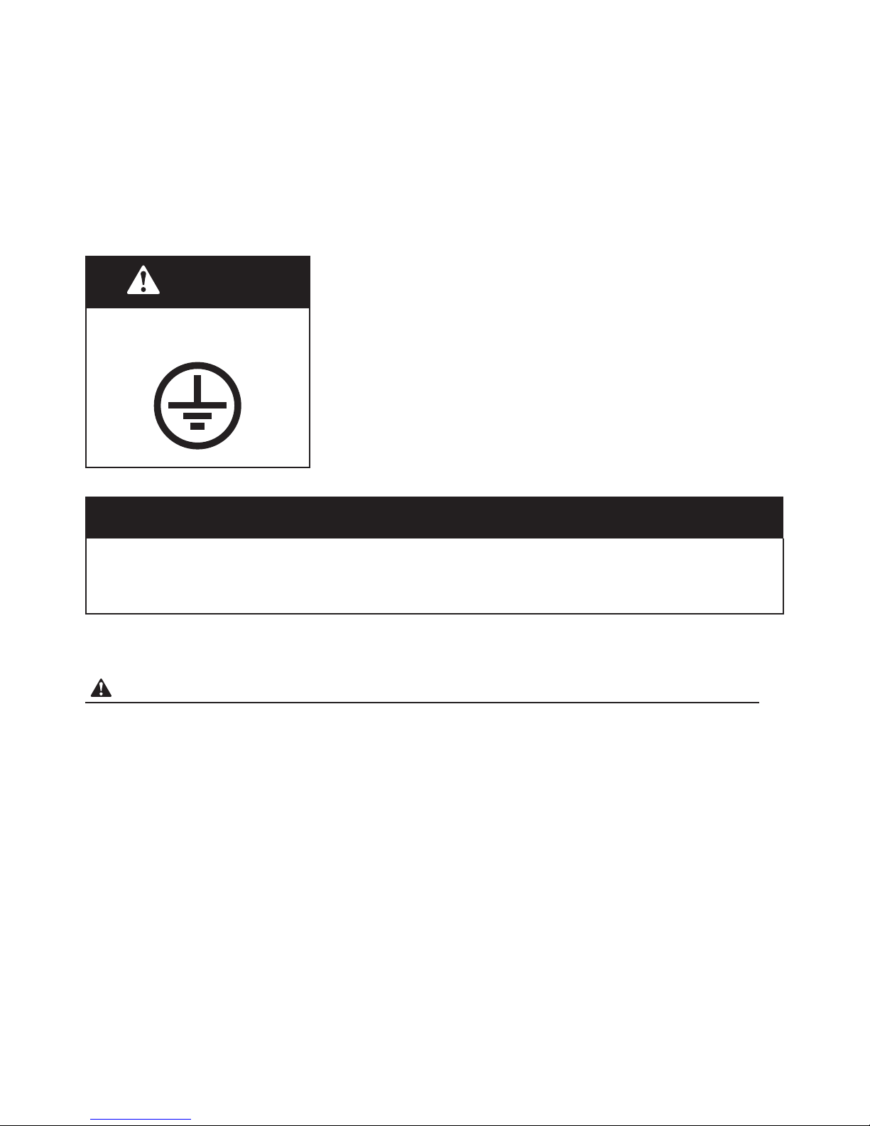
WARNING
If you can’t ensure that the property's power supply is correctly earthed, please don’t
install the unit.
The unit must be installed by a licensed trade person and in accordance with:
• This Installation & Maintenance Guide.
• AS/NZS 3500.4 - ”National Plumbing and Drainage Code Hot Water Supply
Systems-Acceptable Solutions”.
• AS/NZS 3000-Wiring Rules.
• Local authority regulations.
• Building Codes of Australia.
• Local Occupational Health and Safety (OH&S) Regulations.
This unit requires reliable earthing before usage,
otherwise this may result in injury or death.
NOTICE TO CUSTOMERS
This water heater must be installed by a licensed person as required by the Building Act. Only a licensed person will give you a
certificate of compliance, showing that the work complies with all the relevant standards and only a licensed person will have
insurance protecting their workmanship.
Please read and understand this booklet. If you have any questions, please contact our service team on 1300 367 565.
WARNING - HOT WATER CAN BE DANGEROUS
Hot water burns! As a safety precaution, young children should always be supervised around hot water fixtures.
Heat pump water heaters can store water at temperatures that can cause scalding. Water temperatures over 50°C can scald and care
needs to be taken to ensure that injuries do not occur through incorrect use of your water heater.
As heat pump water heaters can generate water temperatures in excess of 50°C, regulations require that a tempering valve be fitted to
the heater to prevent water temperatures going to the home exceeding a pre-set safe maximum. A tempering valve must be connected
to the hot water outlet line from the water heater. The valve must be fitted by an authorised plumber at the time of installation or in
retrofitting to existing systems.
Care should be taken to avoid coming into contact with any pipe work or fixtures associated with the water heater pipe lines. Under NO
circumstances should any ‘home handy man’ type modifications be attempted.
• This appliance is not intended for use by persons (including children) with reduced physical sensory or mental capabilities, or lack of
experience and knowledge, that prevents them from using the appliance safely without supervision or instruction. Children should
be supervised by a responsible person for their safety to ensure that they do not play with the appliance.
• DANGER: Failure to operate the relief valve easing gear at least once every six months may result in the water heater exploding.
Continuous leakage of water from the valve may indicate a problem with the water heater.
• THE INSTALLATION MUST COMPLY WITH THE REQUIREMENTS OF AS/NZS 3500.4, AS/NZS 3000, and all local codes and
regulatory authority requirements. In New Zealand, the installation must conform to the New Zealand Building Code G12.
The power supply must be protected by an individual circuit breaker at the main electrical supply switchboard and rated to suit the size
of the element. The supply to the heat pump water heater can be operated directly from the switchboard or via a remotely mounted
switch as requested by the customer. The heater must be provided with a suitable means for disconnecting the power supply.
Page 3

Section 1: Product Information & Schematics
1-2
Section 2: Safety Information
3
Section 3: Before Installation
4
Section 4: System Installation
5-8
Section 5: System Commissioning
9-10
Section 6: System Operation
11-14
Section 7: System Troubleshooting
15-17
Section 8: System Maintenance
18
Section 9: Warranty
19
GUIDE
CONTENTS
Page 4
Page 1
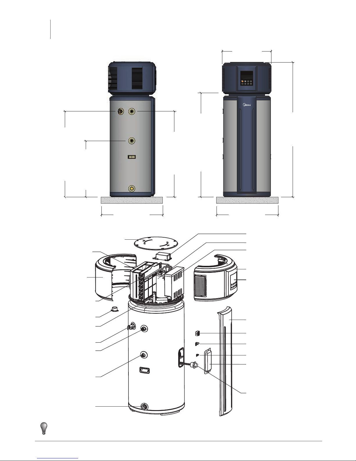
1.2 System Parts
FAN ASSEMBLY
PTR VALVE
TOP COVER
EVAPORATOR FILTER
ANODE ROD
UPPER REAR COVER
UPPER FRONT COVER
HOT WATER OUTLET
COLD WATER INLET
DRAIN PORT
ELECTRIC ELEMENT
FRONT FASCIA
TEMPERATURE SENSOR
ELECTRONIC CONTROL BOX
POWER CONNECT BOX & COVER
COMPRESSOR
DISPLAY
ANODE ROD COVER
ATCO
TCO
ELECTRICAL ELEMENT COVER
NOTE
All pictures in this manual are for explanation purpose only.
They may different from the actual unit.
978 (PTR CONNECTION)
978 (HOT OUTLET)
685 (COLD INLET)
1580 (HEIGHT)
568 (WIDTH)
1215 (ELECTRICAL ENTRY)
MIN 700
(SUPPORT BASE)
MIN 700
(SUPPORT BASE)
PRODUCT
INFORMATION & SCHEMATICS
1
1.1 System Schematics (Dimensions in millimetres)
Page 5
Page 2
Model HP170 (RSJ-15/190RDN3-C)
Modes Economy Hybrid E-Heater
Hot water heating capacity 1500W
Heat Pump E-Heater
2150W
1500W 2150W
Rated input power/current 780W/3.4A 2780W/12.1A 2150W/9.3A
Power supply 220-240V~ 50Hz
Protection Over-load Protector, Temp Controller & Protector, Electric Leakage Protector
Compressor power / E-heater power 440W / 2150W
Water
pipeline
system
Outlet water temperature Default 60°, (60°-70° adjustable)
Water side exchanger Outer coil inner water tank
Inlet / Outlet connector diameter DN20
Drain connector diameter DN20
PTR valve connector diameter DN20
Maximum pressure 1000kPa
Exchanger air
Side
Material Hydrophilic aluminium fin, inner groove copper tube
Motor power 40W
Air inlet / outlet Air in from Sides / Air out from Rear
Fusible link type T20A 250VAC
Refrigerant R134a (800g)
Dimension Ø568×1580mm
Water tank capacity 170L
Net weight 90kg
The test conditions: 1.Test temperature 15/12°C (DB/WB) / 2. Water temperature from 15°C up to 45°C.
Ambient temperature sensor
Suction temperature sensor
CN20
SW3
SW3-2
SW2
SW2-1
Without
2150W
1070W 3200W
1600W
Fan capacitor
1.3 System Specifications
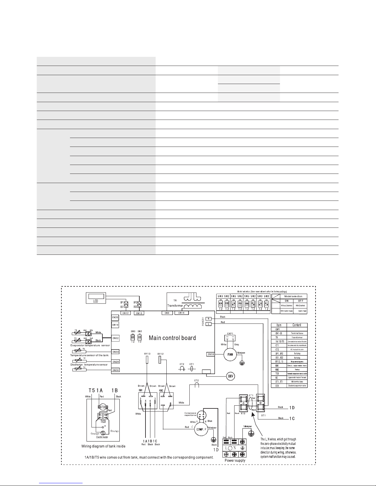
1.4 Electrical Schematic
Page 6

Page 3
Please read thoroughly all of the instructions before installing and operating the unit.
The following safety warnings are very important, always read and obey all safety symbols:
WARNING
• The unit must be earthed effectively.
• A RCD breaker must be installed adjacent to the power
supply.
• Do not remove, cover or deface any permanent instructions or
labels from either the outside or inside of the unit panels.
• Only qualified persons should install the unit in accordance
with local and national regulations and this guide.
• Improper installation may result in water leakage, electric
shock or fire.
• All electric connections should comply with the regulations of
the local power company, local electric utility and this guide.
• Never use an incorrectly rated fuse, otherwise the unit may
break down and cause an electrical fire.
• Do not insert fingers, rods or other objects into the air inlet or
outlet. The fan is rotating at high speed, and may cause injury.
• Never use a flammable spray such as hair spray or lacquer
paint near the unit. It may cause a fire.
• This appliance is not intended for use by persons (including
children) with reduced physical, sensory or mental capabilities,
or lack of experience and knowledge, unless they have been
given supervision or instruction concerning use of the unit
by a person responsible for their safety. Children should be
supervised to ensure that they do not play with the appliance.
• DISPOSAL: Do not dispose of electrical
appliances as unsorted municipal waste, use
separate collection facilities. Contact your
local government for information regarding the
collection systems available.
• If electrical appliances are disposed of in landfills or dumps,
hazardous substances can leak into the groundwater causing
health concerns.
• The unit must be securely fixed, otherwise, noise and vibration
may result.
• Make sure that there are no obstacle around the unit.
• If the unit is to be installed in an area that is subject to lengthy
periods of direct sunlight, additional UV protection for the
display screen is advised.
• In places where there are strong winds (e.g. seaside
locations), fix the unit in an area protected from the wind.
• The PTR Valve should be operated every
6 month to make sure that there is no
restriction of the valve. Please beware of
hot water being expelled from the valve.
The drainage pipe should be well insulated
in order to prevent water inside pipe from
freezing in cold weather.
CAUTION
• The earthing pole must be well grounded. Make sure that any
power supply socket and plug are dry and connected tightly.
• Before cleaning, be sure to stop the operation and isolate the
unit (i.e. turn the isolating switch or breaker off). Otherwise, an
electric shock and injury may be caused.
• Water temperature over 50°C can
cause severe burns or even death
from scalds. Children, disabled and
elderly are at highest risk of being
scalded. Feel water before bathing or
showering. Water temperature limiting
valves are required as per AS 3500.
• Do not operate the unit with a wet
hand as an electric shock may occur.
• A one-way (non-return) valve must be installed on the water
inlet side, as well as a suitable isolation valve.
• It is normal for some water to be released from the PTR valve
during operation. But, if there is a large volume of water, call
our service team for further advice. After long term use, check
the unit base and fittings. If damaged, the unit may sink,
resulting in injury. Arrange the drain pipe to ensure effective
draining. Improper drainage may cause water damage to
surrounding areas such as buildings, furniture etc. Do not
touch the inner parts of the controller or remove the front
panel. Some parts inside are dangerous to touch, and may
cause damage.
• Do not turn off the power supply except for service and
maintenance purposes. A continuous power supply for water
heating is necessary.
• Hydrogen gas is extremely flammable, and may build up if
no water is drawn off for several weeks. To reduce the risk of
injury under these conditions, it is recommended that the hot
water tap is opened for several minutes at the kitchen sink
before using any electrical appliance (i.e. washing machine
/ dishwasher) connected to the hot water system. When
hydrogen is present, there will probably be an unusual sound
such as air escaping through the pipe as the water begins to
flow. There should be no smoking or open flame near the tap
at the time it is open.
Handle
Drainage
pipe
SAFETY
INFORMATION
2
Page 7
Page 4
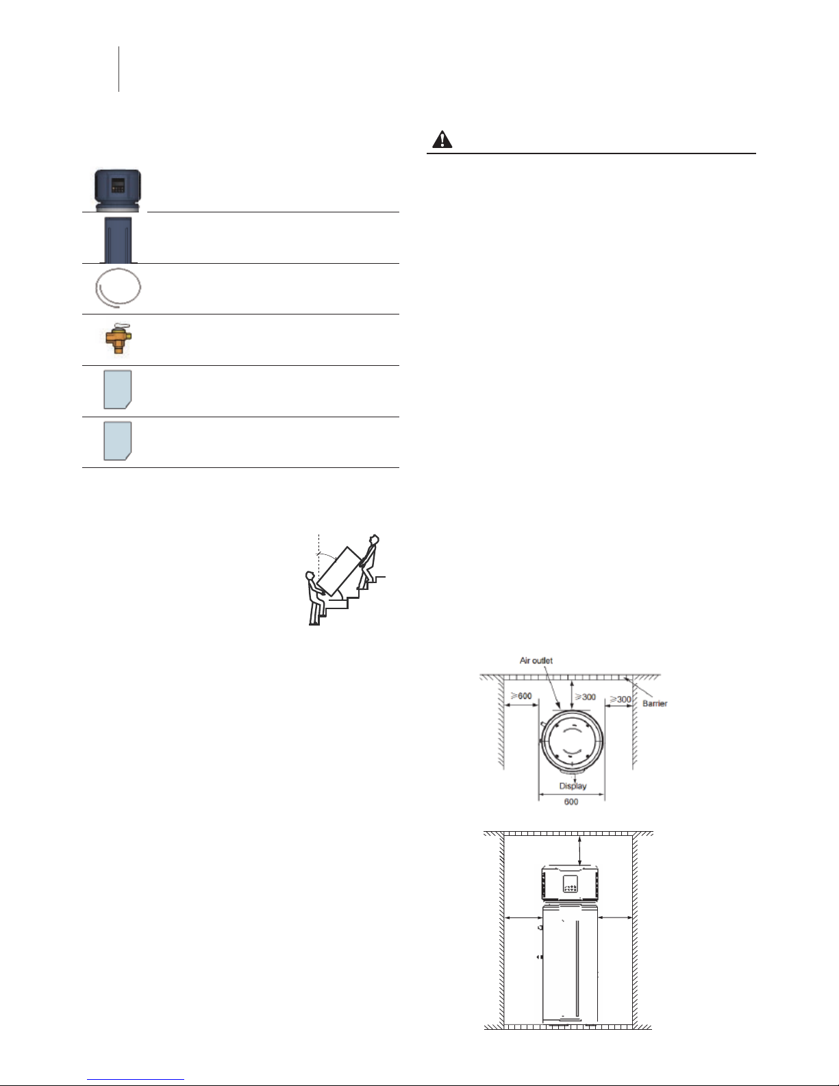
3.1 Unpacking
When unpacking ensure the following items are included:
Main Unit
The Main unit including the storage tank & heat pump
Fascia Cover
A decorative panel to cover the electrical compartments
Condensation Tube
Used for draining condensation from the unit
PTR Valve
Pressure Temperature Relief Valve (May be pre-fitted)
Installation & Maintenance Guide
In-depth installation & maintenance detail on the product
Quick Start Guide
A quick step by step visual look at installation
3.2 Transporting the unit
The following should be adhered to when transporting the unit:
1. Don’t incline the unit more than 25°
from vertical when moving, and keep
it vertical when installing.
2. Avoid scratching or damaging the
unit by using protective coverings
where applicable.
3. As this unit is heavy it needs to
be carried by two or more persons, to avoid injury and/or
damage.
3.3 Location requirements
The following considerations should be addressed when finding a
suitable location:
4. Ensure enough space for installation and future maintenance
is allowed.
5. Both the air inlets & outlet should be free from obstacles &
strong wind.
6. The base surface should be flat (i.e. no more than a 2° incline)
and be able to bear the weight (over 285kg) whilst ensuring
no issue will arise in regards to increased noise and/or
vibration.
7. Operating noise & air flow expelled should not affect others.
8. Ensure no flammable gas is nearby.
9. Positioning should be convenient for plumbing and wiring.
10. Installing indoors may cause indoor temperature fluctuations
and excessive noise.
11. If the unit has to be installed on a metal part of the building,
make sure the electrical insulation meets the relevant local
standard.
12. Securely fixing the unit will assist in avoiding unwanted noise
and/or vibration.
CAUTION
• Consideration must also be made in regards to the ambient air
temperature. Heat pump economy mode operates between
ambient air temperatures of 5°C and 43°C. Temperatures
below this range will rely purely on the electrical element and
the heat pump economy mode will not operate.
• The unit should be located in an area not subject to freezing
temperatures. A unit located in unconditioned spaces
(i.e. garages, basements, etc.) may require the condensate
tubing, and drain piping to be insulated against freezing.
Installing the unit in any of the following places may lead to
malfunction (consult with your representative prior to purchase).
• Site contains mineral oils (e.g. lubricant of cutting machines).
• Seaside areas or where the air contains salt.
• Hot spring areas where corrosive gases exist (e.g. sulphide).
• Factories where the power voltage fluctuates dramatically.
• Inside a recreational vehicle (RV) or cabin.
• Places with direct sunlight and/or other high heat sources.
(If there’s no way to avoid these, a cover may be required).
• Areas where oil may permeate the system (e.g. Kitchens).
• Areas where strong electromagnetic fields exist.
• Areas where flammable gases or materials exist.
• Areas where acidic or alkaline gases exist.
• Other special environments.
3.4 If installed in enclosed space
If the unit is installed in an enclosed space the area must be
greater than 15m³, and must have unrestricted air flow.
As an example, a room that has a 2.5 metre tall ceiling and is 3
metres long by 2 metres wide would contain 15m³.
≥600
≥500
≥300
<
25°
Incline Limit: <25°
BEFORE
INSTALLATION
3
Page 8
Page 5
NOTE
• The cold water inlet and hot water outlet are 3/4” (20mm)
male (external thread) connections.
• The PTR outlet is a 3/4” (20mm) female (internal thread)
connection.
• The Drain port is a 3/4” (20mm) female (internal thread)
connection.
• All hot water plumbing must be insulated for safety & heat
retention.
• The circulating air for every unit should be more than
350m3/h. Make sure there is enough installation space.
Refer dimensional drawing (see page 4).
CAUTION
• Systems must be plumbed as per the above figure. In case of
installing where outside temperatures fall below 5°C, insulation
must be provided for hydraulic components (i.e. piping).
• If the inlet water pressure is less than 150kPa, a pump should
be installed at the water inlet.
• To guarantee the safe usage of tank, a reduction valve should
be installed in the water inlet line if the water pressure exceeds
500kPa.
• Pipes must be heat-resistant and durable.
WARNING
• Do not dismantle the PTR Valve,
• Do not block off the Drainage pipe, it may cause
explosion and/or injury.
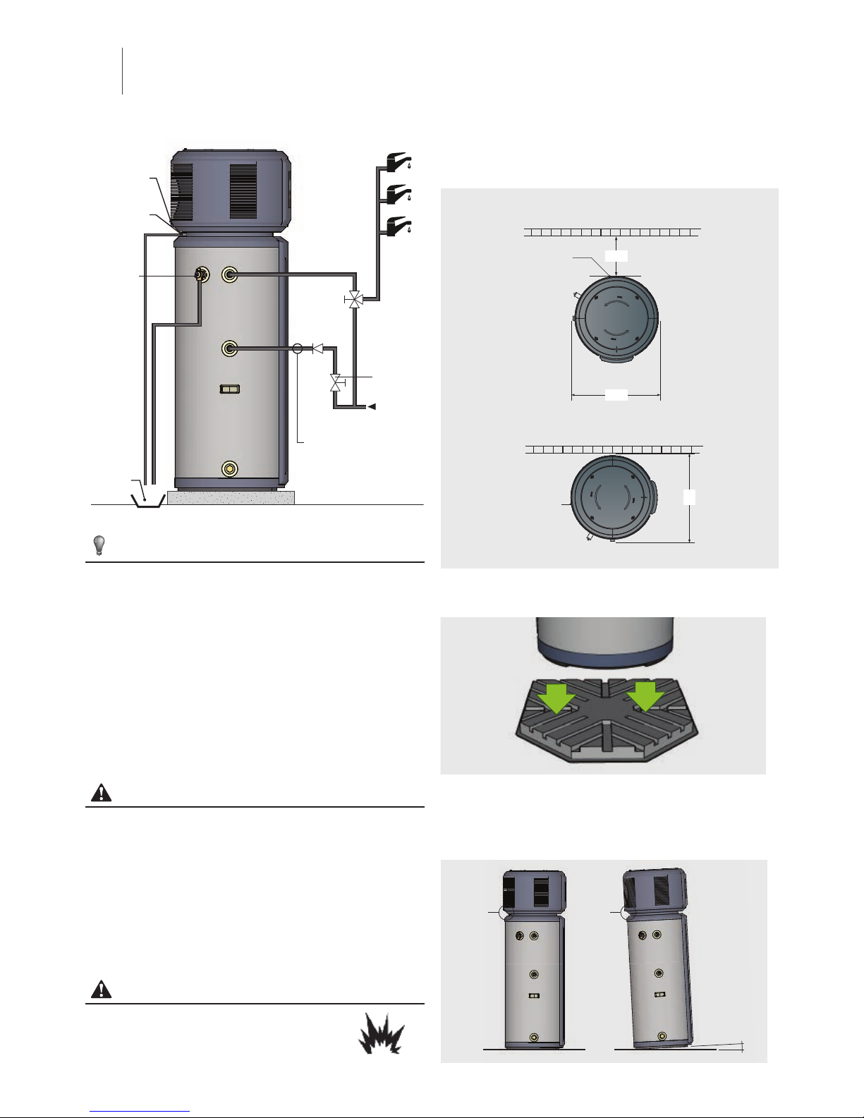
4.2 Installation position requirement
Install the unit with suitable clearance for air flow and plumbing
access (refer to options below)
OPTION 1 (Front On)
DISPLAY
150
AIR OUTLET
600
DISPLAY
AIR
OUTLET
600
WALL
WALL
OPTION 2 (Side)
DISPLAY
AIR
OUTLET
600
WALL
Position the unit on a flat sturdy surface able to bear the weight of a
fully filled unit (allow over 285kg).
PTR VALVE
(RUN TO LEGAL
POINT OF
DISCHARGE)
To ensure correct drainage of condensation from the unit, please
install on a level base. If the base is not level please ensure the
drain location is positioned towards the lower end. Maximum
inclination angle of unit relative to the ground is 2°.
MAX 2
˚
DRAIN
LOCATION
DRAIN
LOCATION
EXPLOSION
COLD WATER EXPANSION VALVE
(May be required to meet
local regulations)
CONDENSATE
OUTLET (UPPER)
CONDENSATE
OUTLET (LOWER)
PTR VALVE
COLD WATER
INLET
HOT WATER
OUTLET
ISOLATION
VALVE
DRAIN PORT
NON-RETURN
VALVE
TEMPERING
VALVE
WATER IN
SUITABLE
DRAIN
4.1 Plumbing Layout
SYSTEM
INSTALLATION
4
Page 9

Page 6
4.3 Plumbing Connections
4.3.1 Condensation draining tube
Fit the condensation tube to the lower port on the rear of the unit and
run to suitable location.
4.3.2 Cold water inlet connection
Connect the cold water line to the cold water inlet position,
ensuring a suitable isolation and non-return valve is included inline.
4.3.3 Hot water outlet connection
Connect the hot water out line to the hot water outlet position.
4.3.3 Pressure temperature relief connection
Connect the pressure temperature relief valve (PTR) and suitably
drain to legal point of discharge
After installation, it must be confirmed that the drainpipe outlet has a
suitable air gap
4.3.4 Tempering Value connections
Plumb a suitable tempering valve between the hot water outlet
and the hot water line to the home.
4.4 Electric Connection
Remove the top cover by releasing the locking screw and rotating
the cover in a clockwise direction. Then simply lift up to remove.
HOT PIPE
(TO TEMP
VALVE)
COLD PIPE
(INC. NON
RETURN
VALVE)
PTR VALVE
(RUN TO LEGAL
POINT OF
DISCHARGE)
Wire electrics by feeding the cable through one of the openings
on the under face of the upper section of the unit and up to the
electrical compartment. Remove the electrical compartment cover
by releasing the two screws. Then connect the wires accordingly.
(Where possible terminate the electrical connection with a suitable
isolating switch (By authorised electrician)
HOT PIPE
(TO TEMP
VALVE)
COLD PIPE
(INC. NON
RETURN
VALVE)
PTR VALVE
(RUN TO LEGAL
POINT OF
DISCHARGE)
HOT PIPE
(TO TEMP
VALVE)
COLD PIPE
(INC. NON
RETURN
VALVE)
PTR VALVE
POINT OF
DISCHARGE)
Reposition the top cover and rotate in an counter-clockwise
direction to lock. Secure with previously removed screw.
HOT PIPE
(TO TEMP
VALVE)
COLD PIPE
(INC. NON
RETURN
VALVE)
PTR VALVE
(RUN TO LEGAL
POINT OF
DISCHARGE)
• Set the electric leakage protector according to the relevant
electric technical standards of local regulations.
• All electrical works shall be properly run using suitable conduit
/ insulation without contacting any of the piping or valves.
For further detail please refer to main electrical layout on page 2
WARNING
The unit must be installed with an RCD near the power supply
and must be effectively earthed.
Page 10

Page 7
4.4 Protective Covers
4.4.1 Fascia Cover
Fit the fascia cover using the locating pins at the top & the locking
bracket at the lower position.
4.4.2 Screen Protection
If the unit is to be installed in an area that is subject to lengthy
periods of direct sunlight, additional UV protection for the display
screen is advised.
4.5 Installation checklist
4.5.1 Location
The flooring beneath the water heater is able to support the
weight of the water heater when filled.
Sufficient room has been allowed to service the water heater.
Sufficient air is available for the heat pump to function (i.e. the
unit is not fitted into any type of closet or small enclosure but
is located in a space greater than 15m³ with no restrictions to
air flow).
The location is free from any corrosive elements in the
atmosphere such as sulphur, fluorine, and chlorine (i.e.
elements found in aerosol sprays, detergents, bleaches,
cleaning solvents, air fresheners, paint, varnish removers,
refrigerants, and many other commercial and household
products).
The location is free from any excessive dust (if so more
frequent cleaning will be required by the user).
4.5.2 Water System Piping
PTR valve (Temperature and pressure relief valve) is properly
installed with a discharge pipe plumbed to suitable drain.
All piping is properly installed and free of leaks.
The unit is completely filled with water.
The tempering valve has been installed per manufacturer’s
instructions.
The condensate drain line is installed and plumbed to suitable
drain.
All hot water lines are appropriately insulated.
4.5.3 Electrical Connections
The water heater is connected to 220~240 VAC.
All wiring sizes and connections comply with all local
applicable codes and the requirements of this guide.
The water heater and electrical supply are properly grounded.
A correctly sized overload fuse or circuit breaker protection
has been installed.
Page 11

Page 8
4.6 Final Installation
Below is an example of a proper heat pump installation along with all plumbing and electrical connections.
Page 12

Page 9
5.1 Filling tank before operation
CAUTION
Operation without water in the
tank may result in the damage of
auxiliary e-heater (element). In case
of such damage, the manufacturer
will not be liable for any damages
caused by this issue.
Before using this unit, please follow the steps below.
• Open the cold water inlet valve.
• Fill the unit with water by opening a hot water tap inside the
home.
• Once water flows from the hot water tap, ensure all air in the
system is bled then close the hot water tap.
5.2 Powering on the unit
CAUTION
Ensure that the tank is full of water and all air has been bled
before turning on the power to the unit.
• Switch on the power to the water heater
• Unlock the control panel by pressing and holding the
CANCEL button for 3 seconds
• Turn heater on by pressing the ON/OFF button on the control
panel twice (Ensure the red LED is illuminated).
• Heater should then start running.
5.3 About Running
This heat pump unit has two kinds of heat sources:
Heat Pump (compressor) and Electric heater (element).
The unit will automatically select the heat source/s to heat the
stored water to the target temperature depending on the mode
selected and the surrounding conditions.
NOTE
• There are different heat-up times at different ambient
temperatures. Normally lower ambient temperature result in
longer heat-up times because of lower effective performance.
500
1000
1500
2000
2500
3000
5715202530323540
43
Capacity(W)
Ambient temp(℃)
15-45
15-55
15-65
Ambient Temperature vs Capacity
500
1000
1500
2000
2500
3000
5715202530323540
43
Capacity(W)
Ambient temp(℃)
15-45
15-55
15-65
1
2
3
4
5
6
7
5715202530323540
43
COP(W/W)
Ambient temp(℃)
15-45
15-55
15-65
Ambient Temperature vs COP (Coefficient of Performance)
500
1000
1500
2000
2500
3000
5715202530323540
43
Capacity(W)
Ambient temp(℃)
15-45
15-55
15-65
1
2
3
4
5
6
7
5715202530323540
43
COP(W/W)
Ambient temp(℃)
15-45
15-55
15-65
0 :0 0: 00
2 :2 4: 00
4 :4 8: 00
7 :1 2: 00
9 :3 6: 00
12: 00: 00
14: 24: 00
5715202530323540
43
Time(h)
Ambient temp(℃)
15-45
15-55
15-65
Ambient Temperature vs Time
• The temperature shown on the display depends on the water
temperature sensor. It is normal that sometimes the display
temperature decreases while the unit is running. This is
caused when the natural convection of the upper hot water
mixes with the lower cold water from inlet tap.
• If the system continuously reports heat pump protection, the
latest error code and the alarm icon will be shown on the
display. The heat pump will stop running and the unit will shift
automatically to E-heater as the backup mode, but the error
code and alarm icon will remain until power is reset.
SYSTEM
COMMISSIONING
5
Page 13

Page 10
5.4 Setting the mode
Operating mode should be selected manually.
Refer to the below table for the modes of operation and the
running temperature ranges & temperature limits:
Operation
mode
Ambient
temp. range
Setting temp.
range
Max. temp.
(Heat pump)
Economy 5°~43° 60°~65° 65°
Hybrid -20°~43° 60°~70° 65°
E-heater -20°~43° 60°~70° -
Temperatures shown in Celsius
Hybrid mode is the recommended mode for best results.
NOTE
• The default heating source is heat pump.
If the ambient temperature range is out of heat pump
operating range, the heat pump will stop running and the unit
will shift automatically to activate E-heater and show the icon
LA on the display. Then if the ambient temperature increases
back into the running range of heat pump again, E-heater will
stop and shift automatically back to heat pump, and the icon
LA will disappear from the display.
• If the target water temperature is higher than maximum
temperature the heat pump can achieve, the unit will activate
the heat pump mode firstly to heat the water as much as it
can, before it stops and the E-heater is activated to continually
heat the water to the target temperature.
• If only using E-heater mode, approx 60% of the tank water
will be heated, so set a higher target water temperature if the
ambient temperature is out of the heat pump running range.
5.5 Automatic functions
5.5.1 Defrosting during water-heating
• During the heat pump running period, if the evaporator
becomes frosted due to low ambient temperatures, the
system will defrost automatically to keep effective performance
(about 5~15min). During defrosting mode, the compressor will
stop, but the fan motor will continue to run.
5.5.2 TCO and ATCO
• The power of the compressor and E-heater will be
automatically shut-off or turned on by the TCO (Thermal
Cut-Out) and the ATCO (Automatic Thermal Cut-Out). If
the water temperature is higher than 78°C, the ATCO will
automatically shut off the power to the compressor and
E-heater, and turn it on if the temperature falls below 68°C.
• If the water temperature is higher than 85°C, the TCO will
automatically shut off the power to the compressor and the
E-heater.
This must then be reset by an authorised service technician.
5.5.3 Automatic E-Heat mode in cold temperatures
• When ambient temperatures are below 5°C, the heat pump
efficiency decreases dramatically. During this time the unit will
automatically shift to E-heater mode.
5.5.4 Protection Mode
• When the self-protection mode activates, the system will be
stopped and start a self-check. Once the error is resolved the
unit will restart.
• When the self-protection mode activates, a beep will sound
every second minute and the alarm icon will flash and error
code will be displayed on screen. Press the cancel button
for 1 second to stop the beep, however the alarm icon will
continue to be displayed on screen until the error is resolved.
• The unit may enter self-protection mode for a number of
circumstances including but not limited to:
• A blocked air inlet or outlet;
• The evaporator is covered with too much dust;
• The unit is receiving incorrect power supply
(exceeding the range of 220-240V).
5.5.5 Error Mode
• In the case of an error occurring, the unit will automatically
shift to E-heater for emergency hot water supply.
• In the case of a serious error, the unit will not start.
• For some errors, a beep will sound 3 times every minute and
the alarm icon will flash. Press the cancel button for 1 second
to stop the beep, however the alarm icon will continue to be
displayed on screen until the error is resolved.
• For all errors please contact an authorised technician.
Page 14

Page 11
① ② ③ ④ ⑤ ⑥ ⑦ ⑧ ⑨
10
11
12
13 14 1615 17 18 19
1
Ambient temperature outside the operational range of the heat pump:
If the ambient temperature is outside the operating range of the heat pump function, the LA icon will be
displayed on screen
2
Wired controller (reserved function):
If a wired controller is connected to the unit then the Wired Controller icon will be displayed on screen
3
Compressor:
If the compressor is activated, the Compressor icon will be displayed on screen
4
E-heater:
If the heating element is activated, the E-heater icon will be displayed on screen
5
Disinfection:
When the unit is in disinfection mode, the Disinfection icon will be displayed on screen
6
Fill water:
When the unit is first powered on (or after the unit is re-powered and the unit was not operational at the
time the power was turned off) the flashing fill water icon will be displayed on screen indicating to fill tank
before making it operational. Once the tank is full, simply unlock the control panel and press the ON/OFF
button (changing the flashing fill water icon to a solid icon). Pressing the ON/OFF button once again will
turn the icon off.
Note: The fill water icon, will not be displayed when the unit is re-powered and the unit was operation at the time the
power was turned off).
7
High temp:
If the target water temperature exceeds 50°C then the High Temp icon will be displayed on screen
8
Alarm:
If the unit is experiencing an error or has gone into protection mode, the flashing Alarm icon will be
displayed on screen along with a series of beeps that will sound 3 times every minute until the protection/
error is resolved or cancelled (by pressing and holding the CANCEL button for 1 second)
6.1 Display Screen
SYSTEM
OPERATION
6
Page 15

Page 12
9
Lock:
If the control panel is in a locked state, the Lock icon will be displayed on screen
10
Economy mode:
If the unit is operating in economy mode, the Economy Mode icon will be displayed on screen.
When selecting mode, the icon will flash if economy mode is selected.
11
Hybrid mode:
If the unit is operating in hybrid mode, the Hybrid Mode icon will be displayed on screen.
When selecting mode, the icon will flash if hybrid mode is selected.
12
E-heater mode:
If the unit is operating in e-heater mode, the E-heater Mode icon will be displayed on screen.
When selecting mode, the icon will flash if e-heater mode is selected.
13
Water temperature setting
When the control panel is not in operation the water temperature setting will display the current water
temperature in the tank;
When setting the desired temperature the water temperature setting will display the desired temperature;
When in error or protection mode the water temperature setting will display the relevant code;
When in query mode, the water temperature setting will display the relevant running parameter.
14
Temp-unit
When the Water temperature setting is displaying a temperature the Degrees Celsius icon will be
displayed on screen.
15
Set Temp
When setting the units desired temperature, the Set Temp icon will be displayed on screen.
16
Clock
The clock will be displayed all the time. When in clock setting mode, the clock will show the setting time,
outside of this mode the clock will display the current set time.
17
Time on
If a TIME ON timer has been set, the TIME ON icon will be displayed on screen.
18
Time off
If a TIME OFF timer has been set, the TIME OFF icon will be displayed on screen.
19
Timer conflict (reserved function)
If a wired controller is connected to the unit and the timer which has been set on the control panel is not
the same as the timer set on the wired controller, then the TIMER CONFLICT icon will display on screen.
Page 16

Page 13
① ② ③ ④ ⑤ ⑥ ⑦ ⑧ ⑨
13 14 1615 17 18 19
Unlocking the control panel
To avoid unintentional changes to the unit, the control panel is fitted with a special automatic lock. The automatic lock is activated after
there is no operation for 1 minute. The screen will display a lock icon
on the top right of the screen when the unit is locked.
• To unlock the control panel, press & hold the cancel button for 3 seconds.
Once unlocked all functions of the control panel are now available.
Turning the unit ON
Before turning the unit on, please ensure the tank is full of water
• To turn the unit ON, unlock the control panel and proceed to press the ON/OFF button.
• Check that the LED light to the top left of the ON/OFF button is illuminated.
The unit is on and operational when the LED light is illuminated. If the LED is not illuminated then the unit is not operational.
Turning the unit OFF
• To turn the unit OFF, unlock the control panel and proceed to press the ON/OFF button.
• Check that the LED light to the top left of the ON/OFF button is no longer illuminated.
Selecting / Changing the desired MODE
• To select / change the desired MODE, unlock the control panel and proceed to press the MODE button.
• Continue to press the MODE button until the desired mode is selected on the screen.
The unit can operate in the three modes: Economy Mode, Hybrid Mode and E-heater Mode.
Hybrid mode is the recommended mode for best results. Refer to page 10 for further explanation of the three modes.
Increase / Up
• To increase the temperature, unlock the control panel and proceed to press the UP ARROW button.
• When setting the clock / timer, to increase the time press the UP ARROW button.
Decrease / Down
• To decrease the temperature, unlock the control panel and proceed to press the DOWN ARROW button.
• When setting the clock / timer, to decrease the time press the DOWN ARROW button.
Setting the 24 Hour Clock
If the intention is to use timers with the unit, the initial clock time will need to be set.
• To set the current time, unlock the control panel and proceed to press the CLOCK button.
The hour value will flash
• Use the ARROW buttons to set the correct hour value.
• Press the CLOCK button again to confirm hour setting.
The minute value will flash
• Use the ARROW buttons to set the correct minute value.
• Finally press the CLOCK button again to confirm the minute setting.
(please note if there is no operation for 10 seconds the unit will automatically confirm the clock setting)
Note: In the event the power to the unit is switched off (i.e brownout), the clock will reset to 00:00. Please note if timers are used,
the clock will need to be reset to the correct time to ensure the timers do not adversely affect the operation. If the power is switched
off while the unit is not on, once the power resumes the unit will revert back to the previous status (off) and will remain off.
Before performing any functions on the control panel it needs to be unlocked.
To unlock the control panel, press & hold the CANCEL button for 3 seconds.
The controller screen can be illuminated by pressing any button. An illuminated
screen does not mean the control panel is unlocked or that the unit is running.
The LED to the top left of the ON/OFF button must be illuminated for the unit to
operate. The screen back light will automatically turn off after 30 seconds of
no operation.
6.2 Control Panel
Page 17

Page 14
Setting the TIME ON Timer
If the Timer is set to TIME ON, the unit will automatically operate once between the setting of the clock and the last 24 hours.
• To set the TIME ON value, unlock the control panel and proceed to press the TIME ON button.
The TIME ON clock will appear below the normal clock with the hour value flashing
• Use the ARROW buttons to set the correct hour value.
• Press the TIME ON button again to confirm hour setting.
The minute value will flash
• Use the ARROW buttons to set the correct minute value in 10 minute increments.
• Press the TIME ON button again to confirm minute setting.
(Please note if there is no operation for 10 seconds the unit will automatically confirm the clock setting)
Setting the TIME ON & TIME OFF Timer
If a Timer is set to TIME ON & TIME OFF, the unit will automatically operate between the setting TIME ON & TIME OFF clock. If the
TIME OFF clock is set to the same TIME ON clock then the TIME OFF clock will automatically be delayed by 10 minutes.
• To set the TIME ON value, unlock the control panel and proceed to press the TIME ON button.
The TIME ON clock will appear below the normal clock with the hour value flashing
• Use the ARROW buttons to set the correct hour value.
• Press the TIME ON button again to confirm hour setting.
The minute value will flash
• Use the ARROW buttons to set the correct minute value in 10 minute increments.
• Press the TIME ON button again to confirm minute & TIME ON setting.
• To set the TIME OFF value, press the TIME OFF button.
The TIME OFF clock will appear below the normal clock to the right of the TIME ON clock with the hour value flashing
• Use the ARROW buttons to set the correct hour value.
• Press the TIME OFF button again to confirm hour setting.
The minute value will flash
• Use the ARROW buttons to set the correct minute value in 10 minute increments.
• Press the TIME OFF button again to confirm minute setting.
(Please note if there is no operation for 10 seconds the unit will automatically confirm the clock setting)
Note: TIME OFF function is only available when a TIME ON function has been set
Cancelling the Timers (TIME ON / TIME OFF)
• To cancel timers, unlock the control panel and then proceed to press the CANCEL button for 3 seconds.
+
Clear Error Code
• To clear the error code, unlock the control panel and then proceed to press both the TIME ON &
CANCEL buttons at the same time to clear all stored error & protection codes.
The beep will sound one time.
+
Enter Query Mode
Query Mode allows for the checking of the units settings & running parameters
• To enter Query Mode, unlock the control panel and then proceed to press both the CLOCK &
CANCEL buttons at the same time for 1 second.
• Press the UP or DOWN ARROW buttons to scroll through the values.
• To exit Query Mode, press the CANCEL button for 1s.
(Please note if there is no operation for 30 seconds the unit will automatically exit Query Mode)
6.3 Button Combination Functions
Page 18

Page 15
7.1 General Troubleshooting
7.1.1 How do I know the unit is working
Check that the LED light next to the on/off button is on. If this light
is not lit, then the system is not operating. Simply press & hold the
cancel button for 3 seconds (unlock the controller) then press the
on/off button to turn the unit on and check that the LED light is lit.
7.1.2 Water from the heat pump is not hot enough
If you find your heat pump is not supplying hot water then this is
most likely related to one of the following:
1. Hot water has been largely consumed and the system
needs to reheat the replenished water.
Check the temperature on the unit and then leave for an hour
and see if this has increased.
(Please note if the system has been completely emptied
recovery may take up to 4 - 5 hours)
2. A timer might be incorrectly set turning the unit off at the
wrong time.
If your screen is showing the 'time on' or 'time off' icon then
it appears a timer has been set. When timers are set this
turns the unit on and off at the set time periods. Remove all
timers, by holding the cancel button for 3 seconds to unlock
the controller, then press the time on or time off buttons,
proceeded by the cancel button to wipe the timers. Should
you wish to set timers for your system please refer to section
6 of this guide on how to do so.
3. The unit has been switched off.
Check the unit and ensure the red LED light is showing. If
not, unlock the controller by holding the cancel button for
3 seconds (the lock icon will disappear from the display
screen). Then simply press the on/off button and now the red
LED light should be lit.
4. The connected power is still in off peak supply only.
We recommend that power is available to the unit 24/7. This
ensures that the unit can work to its maximum efficiency.
If your water is not hot enough and only off peak power is
supplied to the unit then the system cannot operate until the
off peak period is active. If you believe your system is only
available during off peak supply please contact our service
team for further assistance.
5. There may be an issue between the heat pump unit and
the hot water outlet.
Check the controller for the in tank temperature. If the
controller is indicating the tank is at or near the set
temperature then locate the PTR valve on the left hand side
of the unit. Carefully release the PTR valve to release water
directly from the tank.
NOTE: Water expelled may be extremely hot.
Carefully check if the water released is hot. If water is hot,
then there appears to be an issue beyond the heat pump
unit. If so, please contact your plumber or our service team
for further assistance.
SYSTEM
TROUBLESHOOTING
7
Page 19

Page 16
7.1.3 It appears water is leaking from the unit.
The unit is fitted with a condensate release point at the lower
section of the head unit towards the rear of the system. At
time of installation a condensate drain pipe should have been
connected to this point. Check the area where the leak is
occurring to see if this is coming from the condensate drain
pipe. If not and water appears to be leaking from a different
section of the heat pump unit, please contact our service
team for further assistance.
7.1.4 None of the buttons on the controller work
Chances are the controller is in its locked state. Simply press
and hold the Cancel / Unlock button for 3 seconds to unlock
the controller. Now all the buttons will be functional.
7.1.5 It appears unit is set to a low temperature
(i.e. below 50°C)
The temperature shown on the controller is showing the
current temperature in the tank and not the set temperature.
To check the set temperature unlock the unit by pressing the
unlock button for 3 seconds and simply press either the up or
down button to check the set temperature.
7.1.6 Unit is outside a bedroom & the noise is too
much during the night
If the location of your heat pump unit is in close proximity to
a bedroom and your hot water usage pattern is consistently
high at night then the heat pump may operate during the night.
During the quietness of night you may hear the quiet hum of the
heat pump that may cause you some concern. If your hot water
usage pattern is consistently high at night and the noise is a
concern, you may need to set a timer that will in effect turn the
unit off during the night. Note: if a timer is set the heat pump will
only operate during the set period. Please note, if large amounts
of hot water are consumed outside this set period or near the
end of the set period, the system will not be able to bring the
water back up to temperature until the set period kicks in. For
instruction on setting timers, please refer to section 6 of this
guide for further details or contact our service team for further
assistance.
7.1.7 System shows P or E code on controller.
If the controller on your system is presenting with a 'P' or 'E'
code followed by a number, then this is highlighting an error or
protection function within the system.
Please refer to the following table (over page) for further details
or contact our service team for further assistance.
Page 20

Page 17
Display Malfunction Description Corrective Action
E1 Error of sensor T5L (lower water temperature sensor)
The connection between sensor and PCB is broken or the
sensor has experienced an issue.
Contact a qualified person to service the unit.
E2 Tank and wired controller communication error
The connection between controller and PCB is broken or the
PCB has experienced an issue.
Contact a qualified person to service the unit.
E4 Evaporator temperature sensor T3 error
The connection between sensor and PCB is broken or the
sensor has experienced an issue.
Contact a qualified person to service the unit.
E5 Ambient temperature sensor T4 error
The connection between sensor and PCB is broken or the
sensor has experienced an issue.
Contact a qualified person to service the unit.
E6 Compressor discharge temperature sensor TP error
The connection between sensor and PCB is broken or the
sensor has experienced an issue.
Contact a qualified person to service the unit.
E8
Electric leakage error
If PCB current_induction_circuit check the current
difference between L,N >14mA, system consider it as
“electric leakage error”
The connection between some wires have broken or there is
a wiring connection issue.
Contact a qualified person to service the unit.
E9 Compressor suction temperature sensor TH error
The connection between sensor and PCB is broken or the
sensor has experienced an issue.
Contact a qualified person to service the unit.
P8
E-heater open-circuit protection (IEH(Current difference
E-heater on & e-heater off )<1A)
The E-heater has been broken or there is a wiring connection
issue. Contact a qualified person to service the unit.
P2
High discharge temperature protection
Tp>115°C, Protection active
Tp<90°C, Protection inactive
System is potentially blocked, air or water or low refrigerant
(leakage) in system or water temp sensor malfunction.
Contact a qualified person to service the unit.
P4
Compressor overloaded protection (10 seconds after
compressor start up), Current checking starts,
1. Only when compressor is running, if it is >7A , the
compressor will stop for protection.
2. Compressor + e-heater open, if it is >IEH+7,the
compressor will stop for protection.
Compressor broken, system blocked, air or water or too
much refrigerant in system or water temperature sensor
malfunction.
Contact a qualified person to service the unit.
LA
When the ambient temp T4 is out of Heat Pump running
range (5 ~ 43°) Heat Pump will stop, unit will show LA on
the position of clock on display until T4 back to (5 ~ 43°)
It is normal, and repair is not necessary.
NOTE
The diagnostic codes listed above are the most common. If a diagnostic code not listed above is displayed, please contact for
technical assistance.
7.2 Error Codes
Page 21

Page 18
8.1 Cleaning the air filter
(Frequency: Every Month)
• Turn off the power to the unit.
• Remove top cover by releasing the locking screw and rotating in
a clockwise direction.
• Slide the air filter out by lifting directly up.
• Clean filter accordingly and refit in the reverse manner.
8.2 Checking the anode & replacing if required
(Frequency: Every Half Year - Replace if required)
The anode protects the inner lining of your hot water tank. When
the anode become degraded the level of protection is diminished.
It is recommended that anode is periodically checked for its level
of degradation and gets replaced if required.
• Turn off the power, and turn off the cold water inlet valve.
• Open a hot water tap, and decrease the pressure of the inner
container.
• Open the drain port, and release about 20 litres of water.
• Remove the top cover by removing the locking screw and
rotating in a clockwise direction.
• Release the front casing, disconnect the display cable from
the electrical compartment and put aside.
• Locate the anode position on the left hand side.
• Remove the anode cover by releasing the two screws.
• Unscrew the anode and lift directly up.
• Check for degradation.
• If still in suitable condition, refit ensuring an effective seal.
• If anode is in an unsuitable condition, replace with a new
one, ensuring an effective seal.
• Re open the cold water inlet valve.
• Open a hot water tap until hot water flows out, then turn off
the hot water tap.
• Turn on the power to restart the unit.
• Now the unit can be used as normal.
8.3 Cleaning the inner tank and E-Heater
(Frequency: Every Half Year)
It is recommended to clean the inner tank and E-Heater regularly
to maintain efficient performance.
• Turn off the power.
• Close the cold water inlet valve & open a hot water tap.
• Use a flexible pipe to connect the drain port to a suitable
sewage drain. (Note: The min. heat resistance of the drain
pipe must not be less than 93°, if the drain pipe does not
meet the requirement, please open the cold water inlet
valve & open a hot water tap, until the temperature of the
water is suitable for the drain pipe).
• Open the drain port of the water heater; drain out all the
water in the inner tank. If it is needed, use water to wash
the inner tank several times to clear the deposits.
• Close the drain port, re-fill the inner tank with water, and
turn the power back on.
8.4 Operating the PTR valve
(Frequency: Every Half Year - Replace if required)
It is recommended to operate the PTR valve periodically to ensure
water flows freely. If water doesn't flow freely, the PTR valve will
need to be replaced.
• Locate the PTR valve on the left hand side of the unit.
• Carefully release the valve using the lever & release some
water from the tank.
NOTE: Water expelled may be extremely hot.
• If water flows freely the PTR appears to still be in a suitable
working condition.
• If water does not flow freely it would appear the PTR valve is
due for replacement.
• If the PTR valve needs replacing, please contact your plumber
or our service team for further assistance.
8.5 Other maintenance checks
1. Regularly check the electrical wiring for any damage and
contact our service team or your electrician if damage is
evident.
2. In some cold areas (below 0°), if the system will be stopped
for a long time, all the water in the tank should be released
and the tank refilled prior to reuse in case freezing has
occurred inside the inner tank. Failure to do this may result in
severe damage to the heating element.
SYSTEM
MAINTENANCE
8
Page 22

Page 19
The warranty applies to Midea heat pumps installed in a single family dwelling only and is provided only to those acquiring the heat
pump as consumers within the meaning of the Australian Consumer Law. The terms of the warranty are effective from the date the heat
pump is installed. The validity of the product warranty period may be verified by requesting a copy of the certificate of compliance that
accompanied the installation. A compliance certificate is mandatory in all Australian states and territories.
9.1 Warranty period
1. This warranty warrants that the following heat pump
components will remain free of defects for the specified
periods from the date of installation:
• Tank Cylinder - 5 years product / 3 years labour.
• Compressor - 3 years product / 1 year labour.
• All other components supplied, including valves, elements,
thermostats and sacrificial anodes - 1 year.
2. No warranty is given in relation to components not supplied,
for example tempering valves and cold water valve
assemblies used by installers.
3. Subject to the conditions and exclusions specified in this
warranty, the owner may have the defective heat pump
component repaired or replaced covered under this warranty
as soon as reasonably practicable after the consumer has
reported the defect.
9.2 Consumers to register the warranty
For efficient processing of making a claim under this warranty,
consumers are encourage to complete all details on the following
warranty form and send it to the address indicated on the form.
Alternatively warranty can be registered via the web address
indicated on the form.
9.3 Procedure to make a claim under warranty
Upon discovering a suspected defect, consumers should
immediately report the suspected defect:
• To the installer or supplier, if the suspected defect arises as
a result of the installation of the heat pump or relates to any
components not covered by this warranty.
• To Chromagen on the phone number below during the
relevant warranty period, if the suspected defect relates to any
components covered by this warranty.
Please Note: To successfully make a warranty claim, Chromagen
must be advised of the Heat Pumps serial number.
Failure to advise serial number, may delay the service request and or
prevent the service request from being processed.
9.4 Specific exclusions
To the extent permitted by law Chromagen does not accept
liability under this warranty:
• If any component of the heat pump has been installed,
repaired, repositioned or modified by a person other than an
appropriately qualified person approved by Chromagen in
accordance with the installation and maintenance instructions
and relevant local and statutory requirements;
• For loss or damage caused by a fault or defect in the
installation of the heat pump;
• If corrosion has occurred because the anode has not been
changed in accordance with the installation & maintenance
guide;
• If a cold water expansion valve, check valve and strainer is
not fitted in areas where mains pressure is likely to exceed
500kPa;
• For any damage arising as a result of an accident, act of God
or other circumstances beyond Chromagen’s control;
• If the inner cylinder has collapsed as a result of an incorrect
filling and/or commissioning procedure;
• For components not supplied by Chromagen that are used in
the installation of the heat pump water heater e.g. tempering
valves, cold water valve assemblies, etc.
• For extended or implied warranties not formally provided by
Chromagen;
• For external labour or equipment costs (e.g. cranes and lifting
devices) required for repairs;
• For costs incurred for rectifying faults (or perceived faults) not
directly attributed to the heat pump water heater;
• For travel costs of service agents that exceed 30 kilometres;
• For all consequential loss or damage arising from defects that
can lawfully be excluded;
• For any other issues not directly attributable to defects in
components supplied by Chromagen including:
(a) Damage caused by incorrect commissioning;
(b) Leakage from valves not supplied by Chromagen;
(c) Leakage from the pressure temperature relief valve where
the water pressure or temperature exceeds the limits specified
in the installation and maintenance instructions;
(d) Water hammer;
(e) External rust on the storage tank;
(f) Insufficient hot water because:
(i) the consumer refuses to use the auxiliary booster;
(ii) of an incorrectly set or faulty tempering or mixing valve;
(iii) of faulty or incomplete installation;
(iv) the water heater is too small for its required purpose;
(v) of insufficient water flow as a result of “water saving”
tap-ware or appliances;
(vi) of blown fuses, “tripped” electrical switches or
inadequate household electrical wiring;
(vii) insufficient water flow caused by debris accumulating in
water strainer.
9.5 Important Note
The benefits conferred by this warranty are in addition to any
other rights and remedies available to the consumer under a law
in relation to the goods or services to which the warranty relates.
HEAT PUMP
WARRANTY
9
Page 23

Notes:
Customer Details:
Title: Surname: First name:
Installation Address:
Town /Suburb: State: Postcode:
Country:
Telephone: Home: Mob: Email:
System details:
Date of Installation: Installed by:
Model: S/No:
Warranty Registration
Please provide the following details (see reverse side for further instruction):
Images shown are representative only. Product specifications subject to change without notice. For the latest product details and specifications, please visit our website - www.chromagen.com.au.
Chromagen Australia source a range of high quality products & components from a global marketplace to provide Australian consumers with outstanding energy efficient and value for money solutions for their home.
Page 24

Warranty Registration
To register your warranty please ensure to fill out the back of this page.
Cut along dotted line and place in an envelope and address as follows:
Chromagen Australia Pty Ltd
17-23 Redwood Drive,
Dingley Village VIC 3172
Or alternatively register your warranty online at www.chromagen.com.au/warranty
chromagen.com.au | 1300 367 565
Hot Water Solutions | Solar Power Systems | Kitchen Appliances | Air Conditioning
Another Hot Water Solution by
 Loading...