

Page 1
Aqua thermal Series
Midea Building Technologies Division
R32
Service
Manual
All DC Inverter
Page 2

Aqua thermal
Part 1 - General Information
Part 1
General Information
1 Unit Capacities and External Appearance............................................... 4
2 Water outlet temperature range ............................................................ 4
3
Page 3
Aqua thermal
Midea Aqua thermal Service Manual
Model
MC-SU75-RN8L-B
MC-SU90-RN8L-B
MC-SU140-RN8L-B
MC-SU180-RN8L-B
Power
supply
380-415V/3Ph/50Hz
380-415V/3Ph/50Hz
380-415V/3Ph/50Hz
380-415V/3Ph/50Hz
Appearance
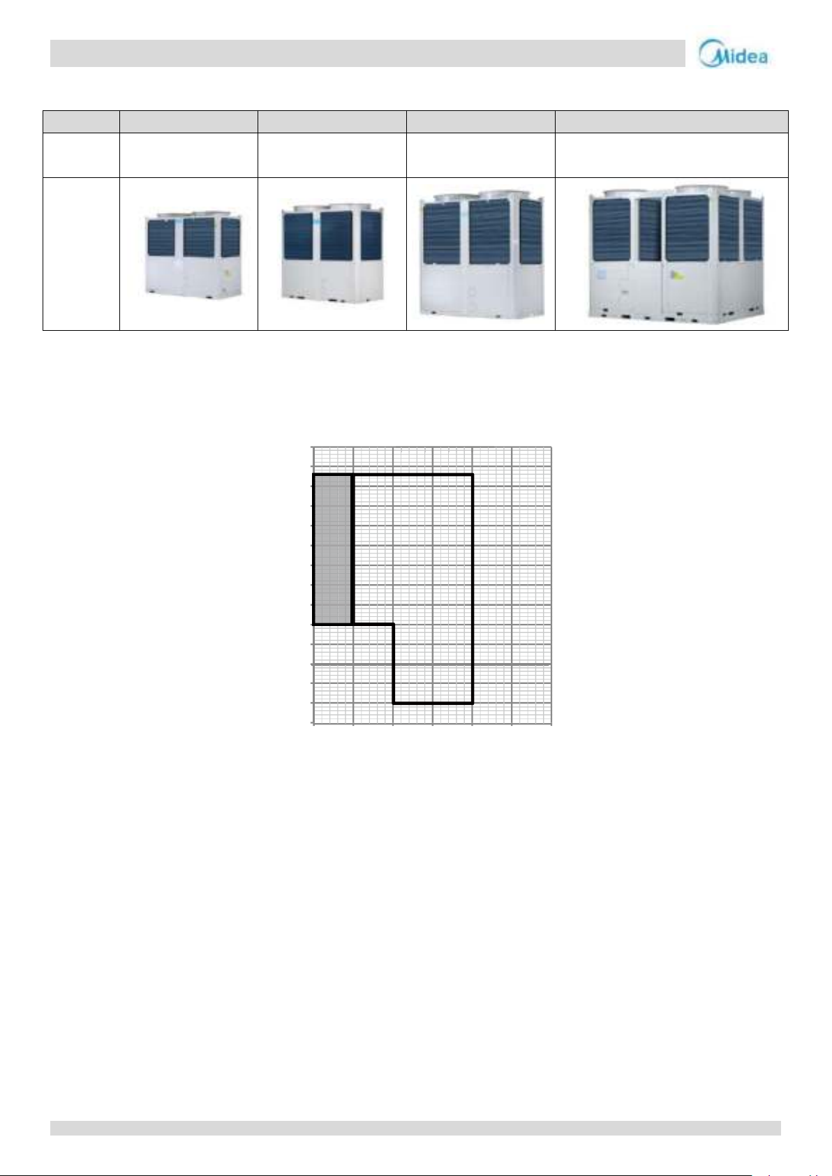
Notes:
① Normal mode
② Low leaving water temperature mode
Low leaving water temperature mode can be set through wired controller, please refer to the Operation Manual for details. If low leaving water
temperature function is effective, the operation range will extend to the red frame above. When the set temperature is less than 5℃, antifreeze
liquid (concentration above 15%) should be added in the water system, otherwise the unit will be damaged.
③ T4: Ambient temperature
Two: Leaving water temperature
Outlet water temperature (℃)
-15
-10
-5
0
5
10
15
20
25
30
35
40
45
50
55
0
5 10
15
20
25
30
outdoor temperature (℃)
COOLING
①
②
1 Unit Capacities and External Appearance
2 Water outlet temperature range
2.1 Cooling operating range
4
Page 4
Aqua thermal
Part 1 - General Information
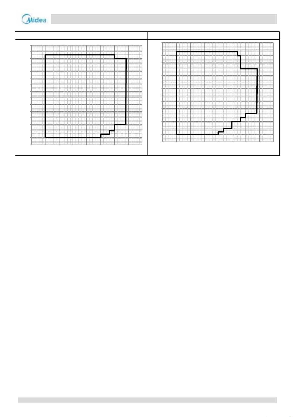
MC-SU75-RN8L-B, MC-SU140-RN8L-B
MC-SU90-RN8L-B, MC-SU180-RN8L-B
Outlet water temperature (℃)
-25
-20
-15
-10
-5
0
5
10
15
20
25
30
35
40
45
50
20
25
30
35
40
45
50
55
60
outdoor temperature (℃)
HEATING
-25
-20
-15
-10
-5
0
5
10
15
20
25
30
35
40
45
50
20 25 30 35 40 45 50 55 60
Outlet water temperature (℃)
outdoor temperature (℃)
2.2 Heating operating range
5
Page 5

Aqua thermal
Midea Aqua thermal Service Manual
6
Page 6

Aqua thermal
Part 2 - Component Layout and Refrigerant Circuits
Part 2
Component Layout and
Refrigerant Circuits
1 Layout of Functional Components .............................................................. 8
2 Piping Diagrams ....................................................................................... 12
3 Refrigerant Flow Diagrams ....................................................................... 21
7
Page 7
Aqua thermal
Midea Aqua thermal Service Manual
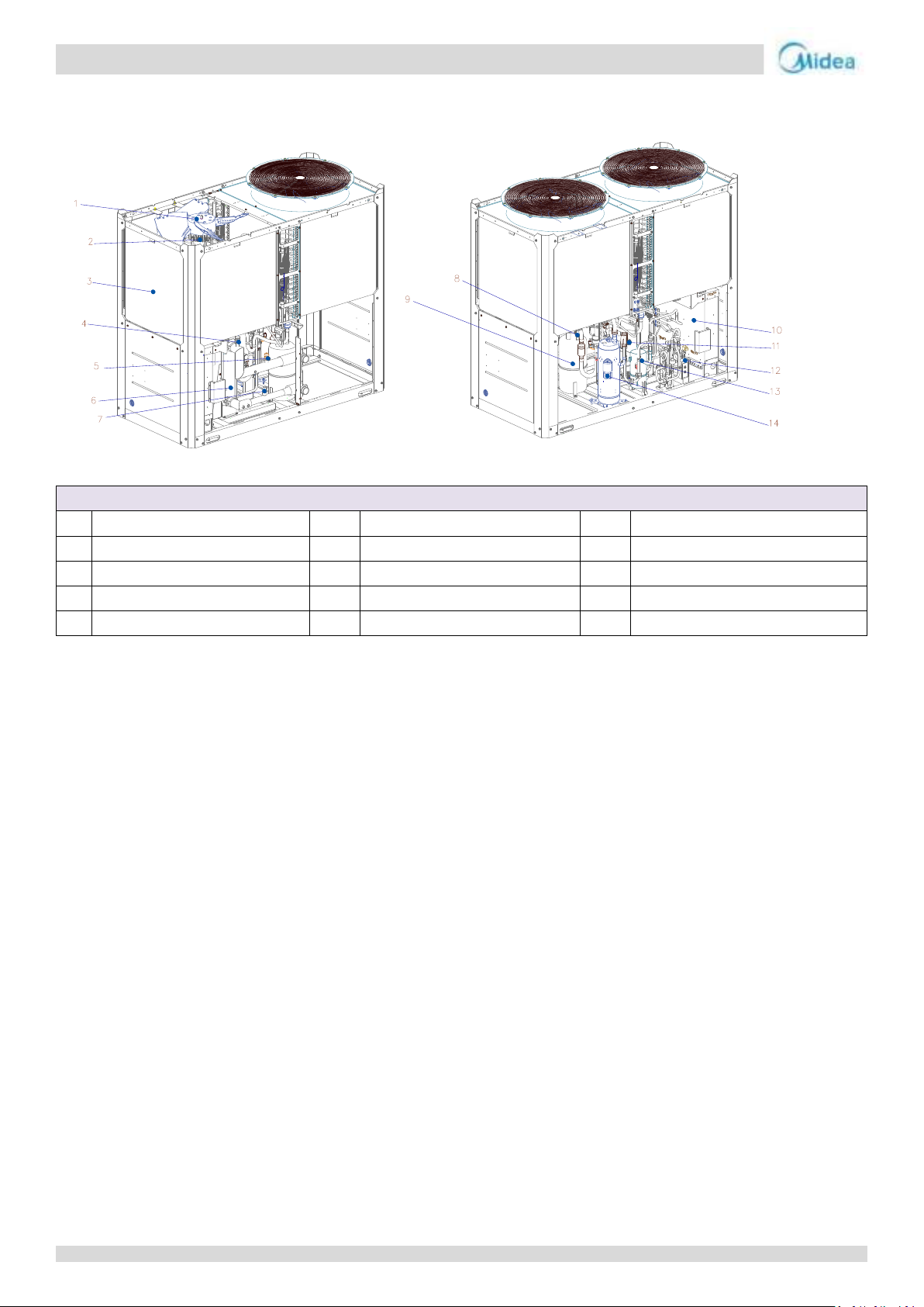
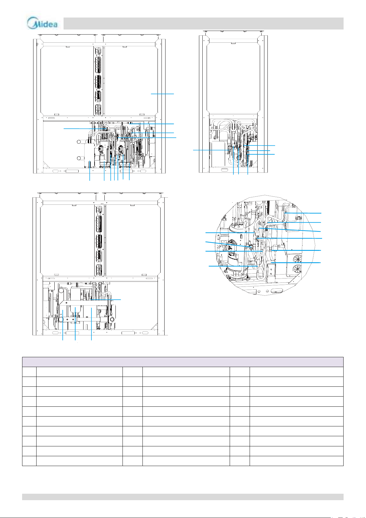
Component list of MC-SU75-RN8L-B
1
Axial fan
6
Plate heating exchanger
11
Four-way valve
2
Brushless DC Motor
7
Flow switch
12
Plate heating exchanger
3
Condenser
8
Safety valve (Refrigerant side)
13
Oil separator
4
Exhaust valve
9
Gas-liquid separator
14
DC inverter scroll compressor
5
Safety valve (Water side)
10
Electric control box
1 Layout of Functional Components
8
Page 8
Aqua thermal
Part 2 - Component Layout and Refrigerant Circuits
Component list of MC-SU90-RN8L-B
1
Compressor 1
13
Filter
24
Liquid storage tank
2
Compressor 2
14
One-way valve
25
Solenoid valve suit
3
Vapor injection solenoid valve 1
15
Electronic expansion valve
26
Pressure sensor
4
Vapor injection solenoid valve 2
16
Plate heating exchanger
27
Safety valve
5/6
High pressure switch
17
Electionic expansion valve
28
Gas-liquid separator
7/8
Filter
18
Heat sink assembly
29
Meter connector
9
Meter connector
19
Single pass solenoid valve suit
30
Low pressure switch
10
Oil seperator
20/22
One way valve
31/33
Filter
11
4-way valve
21
Electronic expansion valve
32
Solenoid valve suit(Oil balance)
12
Condenser
23
Filter
34
Plate heat exchanger
123
4
5
6
9
10
12
13
25
26
11
29
7/8
30
31
33
32
15
14
16
17
18
19
20
21
22
23
242728
34
9
Page 9
Aqua thermal
Midea Aqua thermal Service Manual
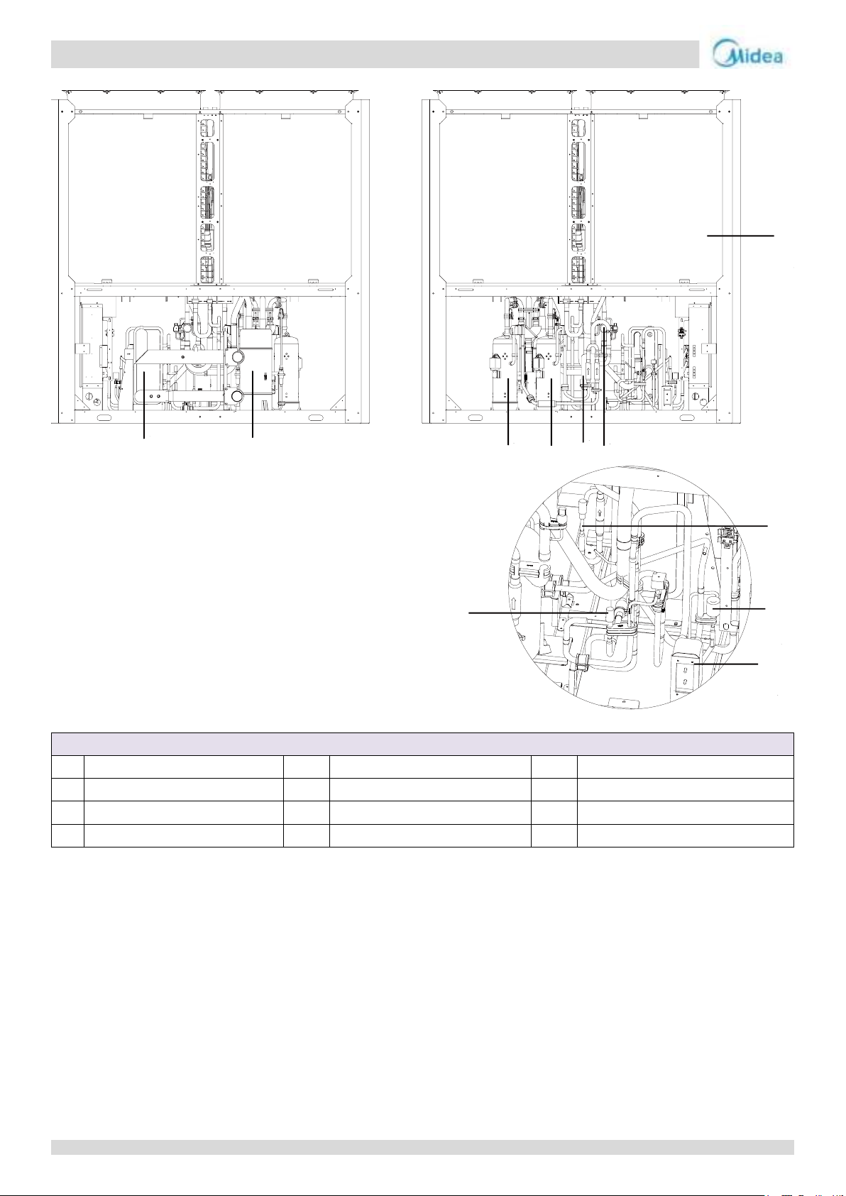
Component list of MC-SU140-RN8L-B
1
DC inverter compressor 1
5
Condenser
9
Electronic expansion valve
2
DC inverter compressor 2
6
Electronic expansion valve
10
Gas-liquid separator
3
Oil seperator
7
Brazing plates heating exchanger
11
Plate heat exchanger
4
4-way valve
8
Electronic expansion valve
1
2
3
4
5
6
7
8
9
10
11
10
Page 10
Aqua thermal
Part 2 - Component Layout and Refrigerant Circuits
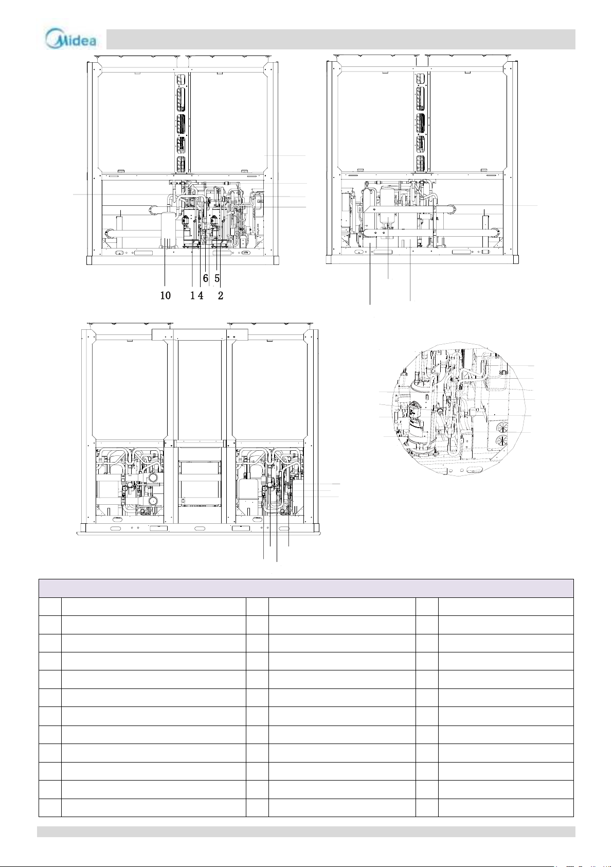
Component list of MC-SU180-RN8L-B
1
DC inverter compressor 1
13
Filter
25
Single pass solenoid valve suit
2
DC inverter compressor 2
14
One-way valve
26
Pressure sensor
3
Enhanced vapor injection solenoid valve 1
15
Electronic expansion valve
27
Safety valve
4
Enhanced vapor injection solenoid valve 2
16
Brazing plates heating exchanger
28
Gas-liquid separator
5
High pressure switch
17
Electionic expansion valve
29
Meter connector
6
High pressure switch
18
Heat sink assembly
30
Low pressure switch
7
Filter
19
Single pass solenoid valve suit
31
Filter
8
Filter
20
One way valve
32
Single pass solenoid valve suit
9
Meter connector
21
Electronic expansion valve
33
Filter
10
4-way valve
22
One way valve
34
Plate heat exchanger
11
Oil seperator
23
Filter
12
Condenser
24
Liquid storage tank
15
14
16
17
18
19
20
21
22
23
3
9
12
13
25
26
24
27
34
28
7/8
11
29
30
31
33
32
11
Page 11
Aqua thermal
Midea Aqua thermal Service Manual
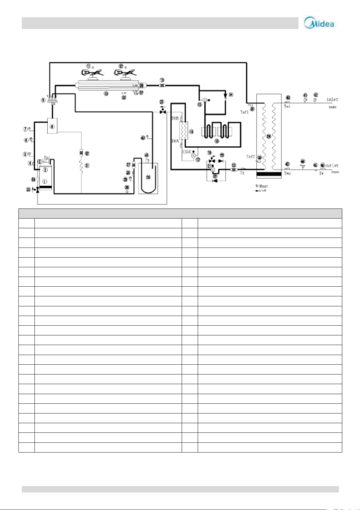
Legend
1
Crankcase heater
25
Solenoid valve
2
DC inverter compressor
26
Vapor-liquid separator
3
Discharge temperature sensor 1
27
Filter
4
Discharge temperature switch 1
28
Suction temperature sensor
5
High pressure switch
29
Low pressure sensor
6
High pressure sensor
30
Low pressure switch
7
Pin valve (Discharge side)
31
Capillary
8
Oil separator
32
Filter
9
4-way-valve
33
Enhanced vapor injection solenoid valve
10
Condenser
34
Muffler
11
DC fan 1
35
Ambient temperature sensor
12
DC fan 2
36
temperature sensor
13
Filter
37
temperature sensor
14
One-way valve
38
Antifreeze temperature sensor 1
15
Heating Electronic expansion valve
39
Antifreeze temperature sensor 2
16
Plate heat exchanger (Economizer)
40
Entering water temperature sensor
17
EVI Electronic expansion valve
41
Safety valve
18
Coil for cooling electronic control board
42
Air purge valve
19
Liquid side bypass solenoid valve
43
Leaving water temperature sensor
20
One-way valve
44
Water flow switch
21
Cooling Electronic expansion valve
45
Water drain
22
One-way valve
46
Total leaving water temperature sensor
23
Filter
47
Pin valve (Suction side)
24
Plate heat exchanger
48
Safety valve
2 Piping Diagrams
MC-SU75-RN8L-B
12
Page 12

Aqua thermal
Part 2 - Component Layout and Refrigerant Circuits
Key components:
1. Compressor:
Maintains pressure differential between high and low pressure sides of the refrigerant system.
2. Fan:
Ventilates the air side heat exchanger.
3. Air side heat exchanger:
In the cooling mode, the heat of the refrigerant from the water side heat exchanger can be released into the air.
In the heating mode, the refrigerant can absorb the heat in the air and provide it to the water side heat exchanger.
4. Water side heat exchanger:
In cooling mode, the refrigerant can absorb heat from the water and reduce the temperature of the water.
In heating mode, the refrigerant can release heat into the water and increase the temperature of the water.
5. Four-way valve:
Controls refrigerant flow direction. Closed in cooling mode and open in heating mode. When closed, the air side heat
exchanger functions as a condenser and water side heat exchanger functions as an evaporator; when open, the air side heat
exchanger functions as an evaporator and water side heat exchanger function as a condenser.
6. Vapor-liquid separator:
Stores liquid refrigerant to protect the compressor from liquid hammering.
7. Oil separator:
Separates oil from gas refrigerant pumped out of the compressor and quickly returns it to the compressor. Separation
efficiency is up to 99%.
8. Plate heat exchanger (Economizer):
In cooling mode, it can improve super-cooling degree and the super-cooled refrigerant can achieve better heat exchange in
indoor side. In heating mode, the refrigerant comes from the plate heat exchanger going to the compressor can enhance the
refrigerant enthalpy and improve the heating capacity in low ambient temperature. Refrigerant volume in plate heat
exchanger is controlled according to temperature different between plate heat exchanger inlet and outlet.
9. Electronic expansion valve:
Controls refrigerant flow and reduces refrigerant pressure.
10. Solenoid valve SV5 (defrost):
Multiple functions for enhancing reliability.
11. Solenoid valve SV6 (by pass):
Increase refrigerant flow.
12. Solenoid valve SV8A, SV8B (injection):
Enhance enthalpy and capacity.
13. High and low pressure switches:
Regulate refrigerant system pressure. When the refrigerant system pressure rises above the upper limit or falls below the
lower limit, the high or low pressure switches turn off, stopping the compressor.
14. Discharge temperature switch:
Protects the compressor from abnormally high temperatures and transient spikes in temperature.
15. High pressure sensor:
Measures compressor discharge side pressure of refrigerant.
16. Low pressure sensor:
Measures compressor suction side pressure of refrigerant.
17. Air purge valve:
Automatically removes air from the water circuit.
18. Safety valve (water side):
Prevents excessive water pressure by opening at 6bar and discharging water from the water circuit.
19. Water flow switch:
Detects water flow rate to protect the compressor and water pump in the event of insufficient water flow.
13
Page 13

Aqua thermal
Midea Aqua thermal Service Manual
20. Safety valve (refrigerant side):
Prevents excessive refrigerant pressure by opening at 42bar and discharging refrigerant from the refrigerant system.
21. Crankcase heater:
Prevents refrigerant from mixing with compressor oil when the compressors are stopped.
22. Water side heat exchanger electric heater:
Protects the water side heat exchanger from ice formation.
23. Water flow switch electric heater:
Protects the water from ice formation.
24. Pin valve (high and low pressure side):
Charges or discharges refrigerant.
25. Capillary:
Normally return oil to the compressor.
26. Wired Controller:
Control and query the operation status of the unit.
14
Page 14
Aqua thermal
Part 2 - Component Layout and Refrigerant Circuits
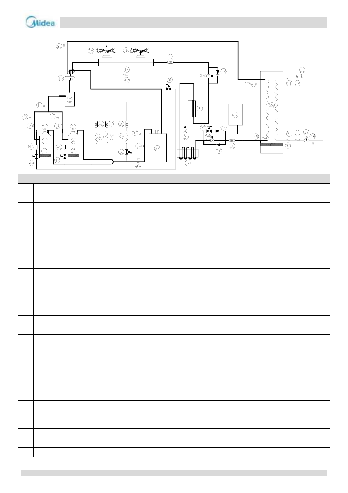
MC-SU90-RN8L-B
Legend
1
Crankcase heater 1
30
System pressure sensor
2
Crankcase heater 2
31
Solenoid valve
3
DC inverter compressor 1
32
Vapor-liquid separator
4
DC inverter compressor 2
33
Pin valve (Suction side)
5
Discharge temperature sensor 1
34
Suction temperature sensor
6
Discharge temperature sensor 2
35
Low pressure switch
7
Discharge temperature switch 1
36
Fast oil return solenoid valve
8
Discharge temperature switch 2
37
Capillary
9
High pressure switch 1
38
Filter
10
High pressure switch 2
39
Capillary
11
Pin valve (Discharge side)
40
Filter
12
Oil separator
41
Capillary
13
4-way-valve
42
Filter
14
Condenser
43
Enhanced vapor injection solenoid valve 1
15
DC fan 1
44
Enhanced vapor injection solenoid valve 2
16
DC fan 2
45
Muffler 1
17
Filter
46
Muffler 2
18
One-way valve
47
Ambient temperature sensor
19
Heating Electronic expansion valve
48
Antifreeze temperature sensor 1
20
Plate heat exchanger (Economizer)
49
Antifreeze temperature sensor 2
21
EVI electronic expansion valve
50
Water side heat exchanger electric heater
22
Coil for cooling electronic control board
51
Entering water temperature sensor
23
Liquid side bypass solenoid valve
52
Safety valve
24
One-way valve
53
Air purge valve
25
Cooling Electronic expansion valve
54
Leaving water temperature sensor
26
One-way valve
55
Total leaving water temperature sensor
27
High pressure tank
56
Water flow switch
28
Filter
57
Manual water drain valve
29
Plate heat exchanger
15
Page 15

Aqua thermal
Midea Aqua thermal Service Manual
Key components:
1. Compressor
Maintains pressure differential between high and low pressure sides of the refrigerant system.
2. Fan:
Ventilates the air side heat exchanger.
3. Oil separator:
Separates oil from gas refrigerant pumped out of the compressor and quickly returns it to the compressor. Separation
efficiency is up to 99%.
4. Vapor-liquid separator:
Stores liquid refrigerant to protect the compressor from liquid hammering.
5. Electronic expansion valve:
Controls refrigerant flow and reduces refrigerant pressure.
6. Four-way valve:
Controls refrigerant flow direction. Closed in cooling mode and open in heating mode. When closed, the air side heat
exchanger functions as a condenser and water side heat exchanger functions as an evaporator; when open, the air side heat
exchanger functions as an evaporator and water side heat exchanger function as a condenser.
7. High and low pressure switches:
Regulate refrigerant system pressure. When the refrigerant system pressure rises above the upper limit or falls below the
lower limit, the high or low pressure switches turn off, stopping the compressor.
8. Discharge temperature switch:
Protects the compressor from abnormally high temperatures and transient spikes in temperature.
9. Air purge valve:
Automatically removes air from the water circuit.
10. Safety valve:
Prevents excessive water pressure by opening at 6bar and discharging water from the water circuit.
11. Water flow switch:
Detects water flow rate to protect the compressor and water pump in the event of insufficient water flow.
12. Pressure sensor:
Measures refrigerant system pressure.
13. Crankcase heater:
Prevents refrigerant from mixing with compressor oil when the compressors are stopped.
14. Water side heat exchanger electric heater:
Protects the water side heat exchanger from ice formation.
15. Water flow switch electric heater:
Protects the water from ice formation.
16. Plate heat exchanger(Economizer):
In cooling mode, it can improve super-cooling degree and the super-cooled refrigerant can achieve better heat exchange in
indoor side. In heating mode, the refrigerant comes from the plate heat exchanger going to the compressor can enhance
the refrigerant enthalpy and improve the heating capacity in low ambient temperature. Refrigerant volume in plate heat
exchanger is controlled according to temperature different between plate heat exchanger inlet and outlet.
17. Pin valve (high and low pressure side):
Charges or discharges refrigerant.
18. Capillary:
Normally return oil to the compressor.
19. Solenoid valve SV4(oil balance):
Quickly return oil to the compressor.
20. Solenoid valve SV5(defrost):
Multiple functions for enhancing reliability.
16
Page 16

Aqua thermal
Part 2 - Component Layout and Refrigerant Circuits
21. Solenoid valve SV6(by pass):
Increase refrigerant flow.
22. Solenoid valve SV8A, SV8B(injection):
Enhance enthalpy and capacity.
17
Page 17
Aqua thermal
Midea Aqua thermal Service Manual
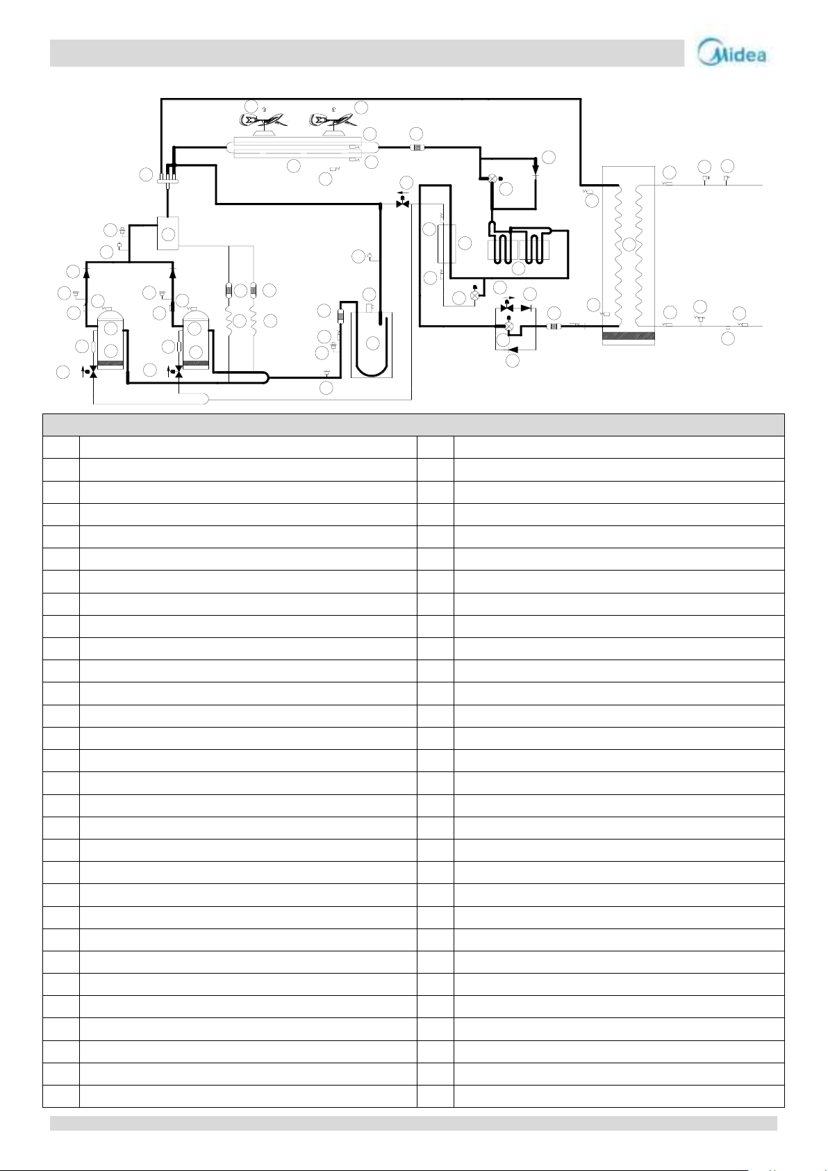
Legend
1
Crankcase heater 1
31
Filter
2
Crankcase heater 2
32
Plate heat exchanger
3
DC inverter compressor 1
33
Solenoid valve
4
DC inverter compressor 2
34
Pin valve (Suction side)
5
Discharge temperature sensor 1
35
Safety valve
6
Discharge temperature sensor 2
36
Vapor-liquid separator
7
Discharge temperature switch 1
37
Filter
8
Discharge temperature switch 2
38
Suction temperature sensor
9
High pressure switch 1
39
Low pressure sensor
10
High pressure switch 2
40
Low pressure switch
11
One-way valve
41
Capillary
12
Pin valve
42
Filter
13
High pressure sensor
43
Capillary
14
Oil separator
44
Filter
15
4-way-valve
45
Enhanced vapor injection solenoid valve 1
16
Condenser
46
Muffler 1
17
DC fan 1
47
Enhanced vapor injection solenoid valve 2
18
DC fan 2
48
Muffler 2
19
Filter
49
Ambient temperature sensor
20
One-way valve
50
temperature sensor
21
Electronic expansion valve
51
temperature sensor
22
temperature sensor
52
Antifreeze temperature sensor 1
23
Plate heat exchanger (Economizer)
53
Antifreeze temperature sensor 2
24
EVI plate heat exchanger refrigerant temperature sensor
54
Entering water temperature sensor
25
Electronic expansion valve
55
Safety valve
26
Coil for cooling electronic control board
56
Air purge valve
27
Liquid side bypass solenoid valve
57
Leaving water temperature sensor
28
One-way valve
58
Water flow switch
29
Electronic expansion valve
59
Water drain
30
One-way valve
60
Total leaving water temperature sensor
53
Taf2
inlet
outlet
Tz
EXVA
W-Heat
Taf1
T4
Twi
Two
Tw
ST1
E
D
S
C
T3B
Th
Tp1
Tp2
SV6
EXVC
T6B
T6A
SV5
T3A
16mm
SV8A
SV8B
1
2
3
4
5
6
7
8
9
10
11
12
13
14
15
16
17
18
19
20
21
23
24
25
26
27
22
28
29
30
31
32
33
36
34
35
37
38
39
40
41
42
43
44
45
46
47
48
49
51
50
52
54
55
56
57
58
59
60
EXVB
MC-SU140-RN8L-B
18
Page 18

Aqua thermal
Part 2 - Component Layout and Refrigerant Circuits
Key components:
1. Compressor
Maintains pressure differential between high and low pressure sides of the refrigerant system.
2. Fan:
Ventilates the air side heat exchanger.
3. Air side heat exchanger:
In the cooling mode, the heat of the refrigerant from the water side heat exchanger can be released into the air.
In the heating mode, the refrigerant can absorb the heat in the air and provide it to the water side heat exchanger.
4. Water side heat exchanger:
In cooling mode, the refrigerant can absorb heat from the water and reduce the temperature of the water.
In heating mode, the refrigerant can release heat into the water and increase the temperature of the water.
5. 4-way valve:
Controls refrigerant flow direction. Closed in cooling mode and open in heating mode. When closed, the air side heat
exchanger functions as a condenser and water side heat exchanger functions as an evaporator; when open, the air side heat
exchanger functions as an evaporator and water side heat exchanger function as a condenser.
6. Vapor-liquid separator:
Stores liquid refrigerant to protect the compressor from liquid hammering.
7. Oil separator:
Separates oil from gas refrigerant pumped out of the compressor and quickly returns it to the compressor. Separation
efficiency is up to 99%.
8. Plate heat exchanger (Economizer):
In cooling mode, it can improve super-cooling degree and the super-cooled refrigerant can achieve better heat exchange in
indoor side. In heating mode, the refrigerant comes from the plate heat exchanger going to the compressor can enhance the
refrigerant enthalpy and improve the heating capacity in low ambient temperature. Refrigerant volume in plate heat
exchanger is controlled according to temperature different between plate heat exchanger inlet and outlet.
9. Electronic expansion valve:
Controls refrigerant flow and reduces refrigerant pressure.
10. Solenoid valve SV5 (defrost):
Multiple functions for enhancing reliability.
11. Solenoid valve SV6 (by pass):
Increase refrigerant flow.
12. Solenoid valve SV8A, SV8B (injection):
Enhance enthalpy and capacity.
13. High and low pressure switches:
Regulate refrigerant system pressure. When the refrigerant system pressure rises above the upper limit or falls below the
lower limit, the high or low pressure switches turn off, stopping the compressor.
14. Discharge temperature switch:
Protects the compressor from abnormally high temperatures and transient spikes in temperature.
15. High pressure sensor:
Measures compressor discharge side pressure of refrigerant.
16. Low pressure sensor:
Measures compressor suction side pressure of refrigerant.
17. Air purge valve:
Automatically removes air from the water circuit.
18. Safety valve (water side):
Prevents excessive water pressure by opening at 6bar and discharging water from the water circuit.
19. Water flow switch:
Detects water flow rate to protect the compressor and water pump in the event of insufficient water flow.
20. Safety valve (refrigerant side):
Prevents excessive refrigerant pressure by opening at 42bar and discharging refrigerant from the refrigerant system.
21. Crankcase heater:
Prevents refrigerant from mixing with compressor oil when the compressors are stopped.
22. Water side heat exchanger electric heater:
Protects the water side heat exchanger from ice formation.
19
Page 19

Aqua thermal
Midea Aqua thermal Service Manual
23. Water flow switch electric heater:
Protects the water from ice formation.
24. Pin valve (high and low pressure side):
Charges or discharges refrigerant.
25. Capillary:
Normally return oil to the compressor.
26. Wired Controller:
Control and query the operation status of the unit.
MC-SU180-RN8L-B
The piping diagrams is the same as MC-SU90-RN8L-B. MC-SU180-RN8L-B system consists of two independent MC-SU90-RN8L-B
systems.
20
Page 20
Aqua thermal
Part 2 - Component Layout and Refrigerant Circuits
inlet
outlet
E
D
S
C
inlet
outlet
E
D
S
C
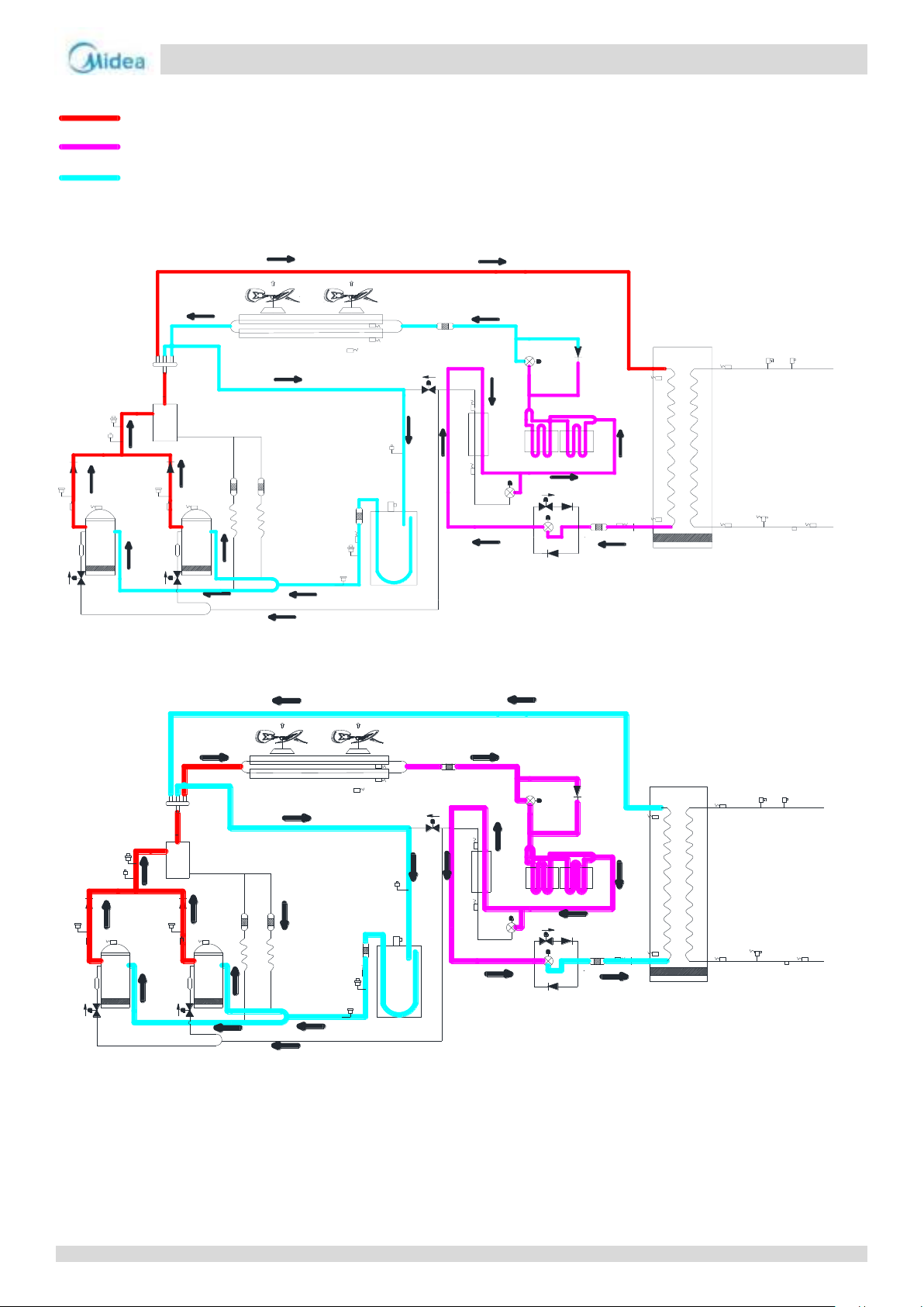
High temperature, high press gas
High temperature, high press liquid
Low temperature, low press
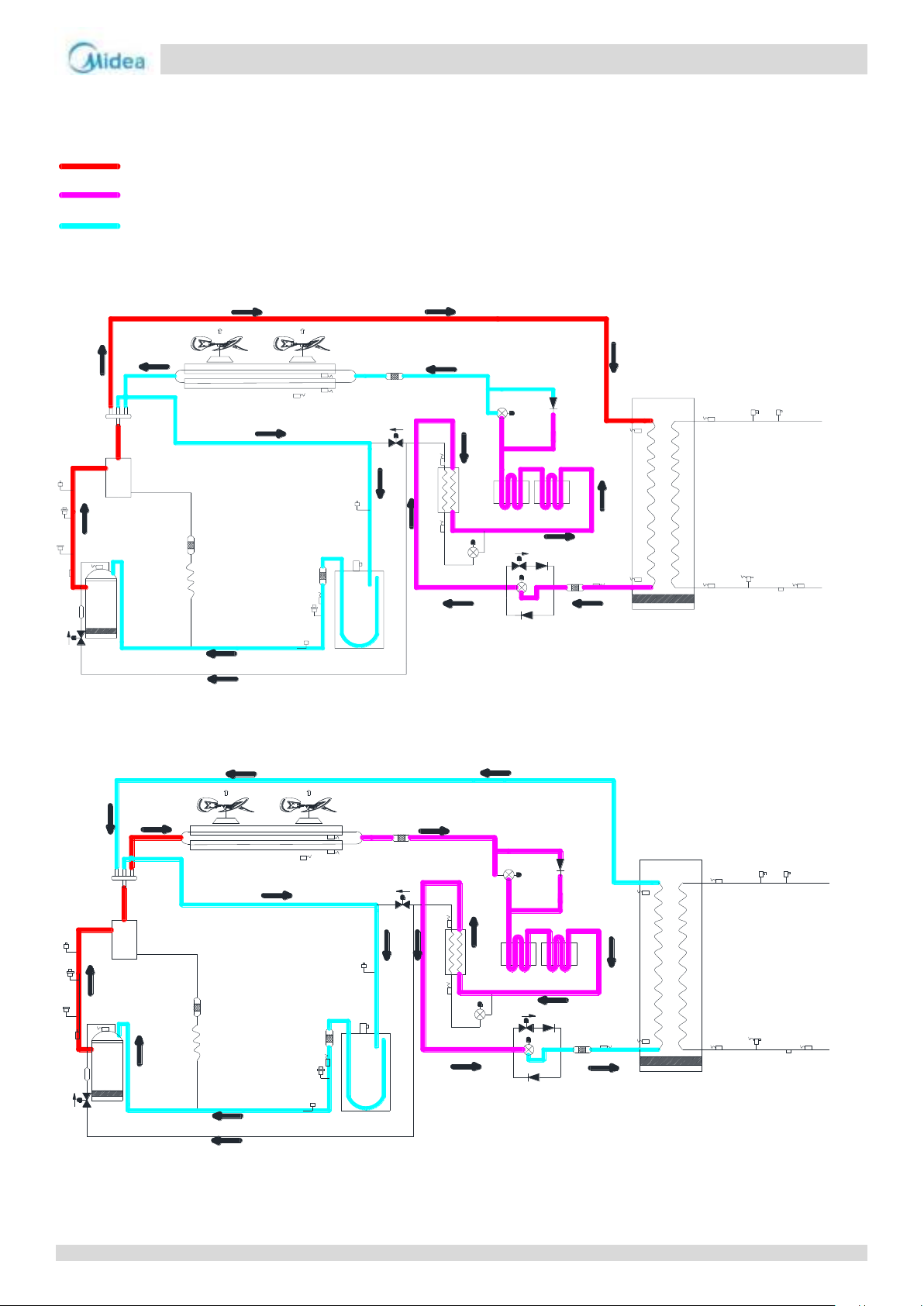
3 Refrigerant Flow Diagrams
MC-SU75-RN8L-B
Heating operation
Cooling and defrosting operation
21
Page 21
Aqua thermal
Midea Aqua thermal Service Manual
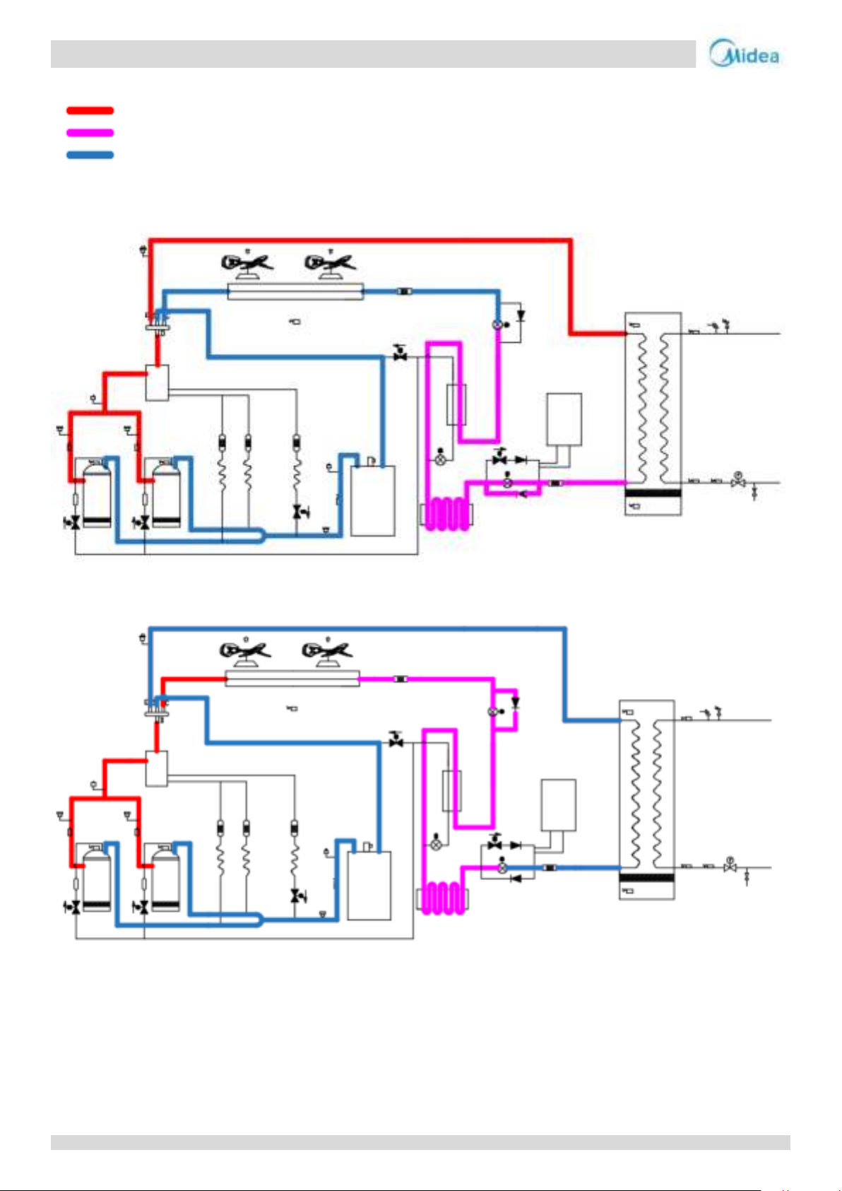
Heating operation
High temperature, high press gas
High temperature, high press liquid
Low temperature, low press
MC-SU90-RN8L-B
Cooling and defrosting operation
22
Page 22
Aqua thermal
Part 2 - Component Layout and Refrigerant Circuits
inlet
outlet
E
D
S
C
inlet
outlet
E
D
S
C
High temperature, high press gas
High temperature, high press liquid
Low temperature, low press
MC-SU140-RN8L-B
Heating operation
Cooling and defrosting operation
MC-SU180-RN8L-B
The refrigerant flow diagrams is same as MC-SU90-RN8L-B. MC-SU180-RN8L-B system consists of two independent
MC-SU90-RN8L-B systems.
23
Page 23

Aqua thermal
Midea Aqua thermal Service Manual
24
Page 24

Aqua thermal
Part 3 - Control
Part 3
Control
1 General Control Scheme Flowchart .......................................................... 26
2 Stop Operation ........................................................................................ 27
3 Standby Control ....................................................................................... 27
4 Startup Control ........................................................................................ 28
5 Normal Operation Control ....................................................................... 31
6 Protection Control ................................................................................... 37
7 Special Control ......................................................................................... 41
25
Page 25
Aqua thermal
Midea Aqua thermal Service Manual
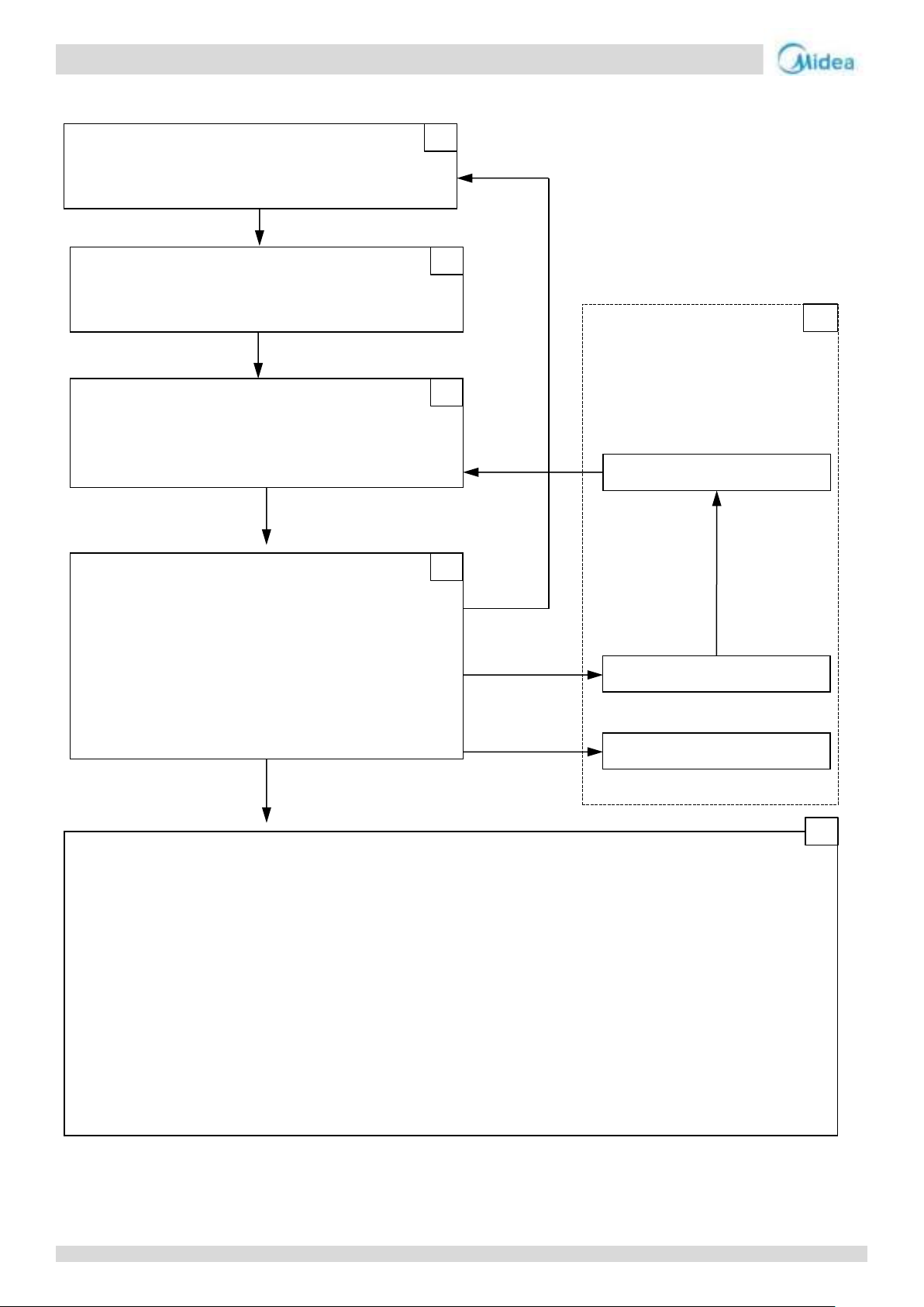
Easy control
Conditions met
for defrosting
On
Special control
Outdoor unit duty cycling
TEMP-SWITCH control
Defrosting operation
7
Stop operation
System stops
2
Standby control
Water pump control
3
Startup control
Startup control for cooling operation
4
Normal operation control
Outdoor fan control
5
Protection control
Water side heat exchanger low pressure protection control
6
On
1 General Control Scheme Flowchart
Abnormal shutdown
Crankcase heater control
Compressor startup delay control
Startup control for heating operation
Component control during normal operation
Compressor output control
Compressor step control
Water pump select control
Four-way valve control
Electronic expansion valve control
High pressure protection control
Low pressure protection control
Discharge temperature protection control
Compressor and Inverter Module Protection Control
Voltage protection control
DC fan motor protection control
Water side heat exchanger anti-freeze protection control
Air side heat exchanger high temperature protection control
Water side heat exchanger temperature difference protection control
Water side heat exchanger low temperature protection control
Note:
1. Numbers in the top right-hand corners of boxes indicate the relevant section of text on the following pages.
26
Page 26
Aqua thermal
Part 3 - Control
Notes:
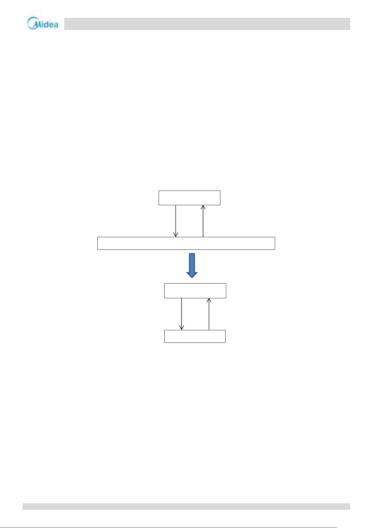
1. Tp1: discharge temperature sensor 1;
2. Tp2: discharge temperature sensor 2.
Ambient temperature < 35 oC
Ambient temperature > 40 oC
Crankcase heater off
Crankcase heater is controlled according to discharge temperature
Min (Tp1, Tp2) < 40 oC
Min (Tp1, Tp2) > 50 oC
Crankcase heater off
Crankcase heater on
2 Stop Operation
The stop operation occurs for one of the following reasons:
1. Abnormal shutdown: in order to protect the compressors, if an abnormal state occurs the system makes a stop with thermo
off operation and an error code is displayed on the outdoor unit’s PCB digital displays and on the user interface.
2. The system stops when the set temperature has been reached.
In order to prevent the compressor from starting and stopping frequently and to balance the pressure in the refrigeration
system, forcibly stop the compressor for 7 minutes before starting. (Except for special controls such as defrosting).
3 Standby Control
3.1 Crankcase Heater Control
The crankcase heater is used to prevent refrigerant from mixing with compressor oil when the compressors are stopped. The
crankcase heater is controlled according to the outdoor ambient temperature and discharge temperature. When the outdoor
ambient temperature is above 40°C, the crankcase heater is off; when the outdoor ambient temperature is below 35°C, the
crankcase heater is controlled according to discharge temperature.
3.2 Water Pump Control
When the outdoor unit is in standby, the circulator pump run continuously.
27
Page 27
Aqua thermal
Midea Aqua thermal Service Manual
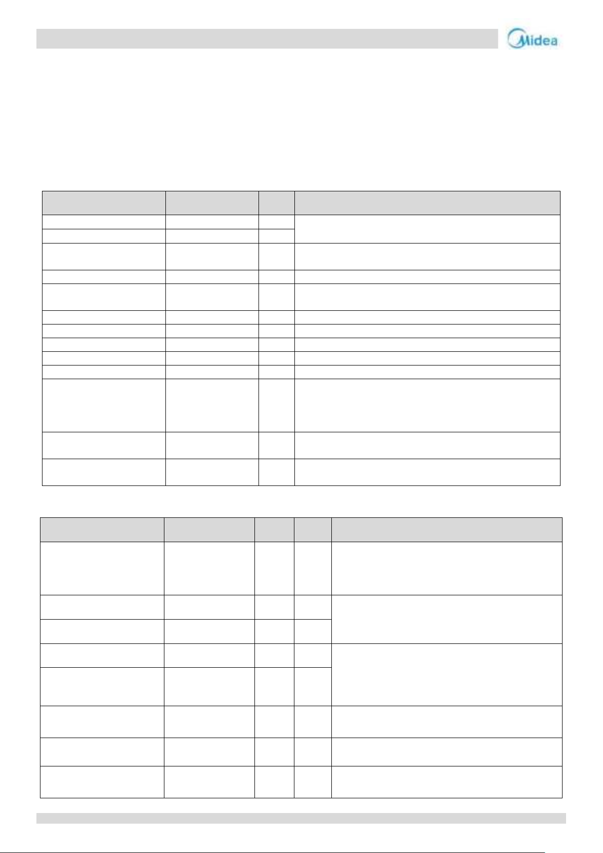
Component
Wiring diagram label
90kW
Control functions and states
DC fan motor A
Fan A
●
Startup after 4-way valve changes refrigerant flow direction.
Controlled according to discharge pressure.
DC fan motor B
Fan B
●
Electronic expansion valve A
EXVA
●
Step from 0 to 480. Controlled according to discharge temperature
superheat.
Electronic expansion valve B
EXVB
●
Step 480
Electronic expansion valve C
EXVC
●
Step from 0 to 480. Controlled according to temperature difference
between economizer plate heat exchanger inlet and outlet.
Four-way valve
ST1
●
On
Solenoid valve (oil balance)
SV4
●
Closed for 200s, open for 600s, then closed.
Solenoid valve (defrost)
SV5
●
Closed
Solenoid valve (by pass)
SV6
●
Closed
Solenoid valve (injection)
SV8A/B
●
Open
Water flow switch
Water-SW
●
After water pump (field supplied) is turned on for 2min, if water flow
switch is open, water pump stops and water flow error code
appears. The compressor can be started after the water flow is
normal.
Electric auxiliary heater (pipe)
-
●
Controlled according to ambient temperature and total water outlet
temperature.
Crankcase heater
CCH
●
Controlled according to ambient temperature and discharge
temperature.
Component
Wiring diagram label
75kW
140kW
Control functions and states
Water pump
PUMP
●
●
Non-standard component: After the pump is turned on for
2 minutes, detect the water flow switch continuously. The
compressor can be started only after the water flow is
normal.
Inverter compressor 1
BP1
●
●
Control the outlet water temperature. The operating
increased and decreased frequency is 1Hz/s, and is
executed according to the starting platform.
Inverter compressor 2
BP2
●
●
Inverter fan1
FAN1
●
●
Startup after 4-way valve changes refrigerant flow
direction. Controlled according to ambient temperature,
discharge pressure and compressor frequency.
Inverter fan 2
FAN2
●
●
Electronic expansion valve
EXV-A
●
●
Step from 0 to 480. Controlled according to discharge
temperature superheat.
Electronic expansion valve
EXV-B
●
●
Step 480P
Electronic expansion valve
EXV-C
●
●
Enhanced vapor injection EXV,Step from 0 to 480.
Controlled according to temperature difference between
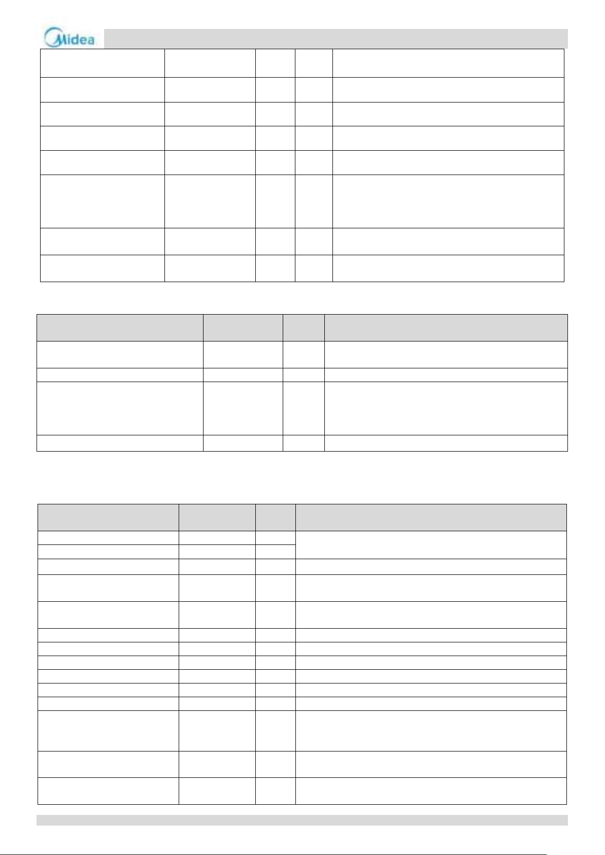
4 Startup Control
4.1 Compressor Startup Delay Control
In initial startup control and restart control (except in defrosting operation), compressor startup is delayed such that a minimum
7 minutes has elapsed since the compressor stopped, in order to prevent frequency compressor on/off and to equalize the
pressure within the refrigerant system.
4.2 Startup Control for Heating Operation
For MC-SU90-RN8L-B:
For MC-SU75-RN8L-B and MC-SU140-RN8L-B:
28
Page 28
Aqua thermal
Part 3 - Control
economizer plate heat exchanger inlet and outlet.
Four-way valve
ST1
●
●
Open
Solenoid valve (defrost)
SV5
●
●
Closed
Solenoid valve (by pass)
SV6
●
●
Closed
Solenoid valve (injection)
SV8A/B
●
●
Open
Water flow switch
Water-SW
●
●
After water pump (field supplied) is turned on for 2min, if
water flow switch is open, water pump stops and water
flow error code appears. The compressor can be started
after the water flow is normal.
Electric auxiliary heater (pipe)
-
●
●
Controlled according to ambient temperature and total
water outlet temperature.
Crank case heater
CCH
●
●
Controlled according to ambient temperature and
discharge temperature.
Component
Wiring diagram
label
180kW
Control functions and states
Inverter compressor
BP1/2
●
Compressor startup program selected according to ambient
temperature.
DC fan motor
FAN
●
Fan run at maximum speed1.
Electronic expansion valve
EXV
●
Position (steps) from 0 (fully closed) to 480 (fully open),
controlled according to outdoor ambient temperature,
discharge temperature, suction superheat, compressor speed
and refrigerant system pressure.
Four-way valve
ST1
●
On
Component
Wiring diagram
label
90kW
Control functions and states
DC fan motor A
Fan A
●
According to ambient temperature, compressor frequency and air
side heat exchanger refrigerant total outlet temperature.
DC fan motor B
Fan B
●
Electronic expansion valve A
EXVA
●
Step 480
Electronic expansion valve B
EXVB
●
Step from 0 to 480. Controlled according to suction temperature
superheat.
Electronic expansion valve C
EXVC
●
Step from 0 to 480. Controlled according to temperature difference
between economizer plate heat exchanger inlet and outlet.
Four-way valve
ST1
●
Closed
Solenoid valve (oil balance)
SV4
●
Closed for 200s, open for 600s, then closed.
Solenoid valve (defrost)
SV5
●
Closed
Solenoid valve (by pass)
SV6
●
Open for 600s then closed.
Solenoid valve (injection)
SV8A/B
●
Open
Water side heat exchanger heater
-
●
According to water side heat exchanger anti-freezing temperature.
Water flow switch
Water-SW
●
After water pump (field supplied) is turned on for 2min, if water flow
switch is open, water pump stops and water flow error code appears.
The compressor can be started after the water flow is normal.
Water flow switch heater
●
Controlled according to ambient temperature, water inlet
temperature and water outlet temperature.
Crank case heater
CCH
Controlled according to ambient temperature and discharge
temperature.
For MC-SU180-RN8L-B:
Notes: 1. Refer to Table 3-4.1 in Part 3, 5.8 “Outdoor Fan Control”.
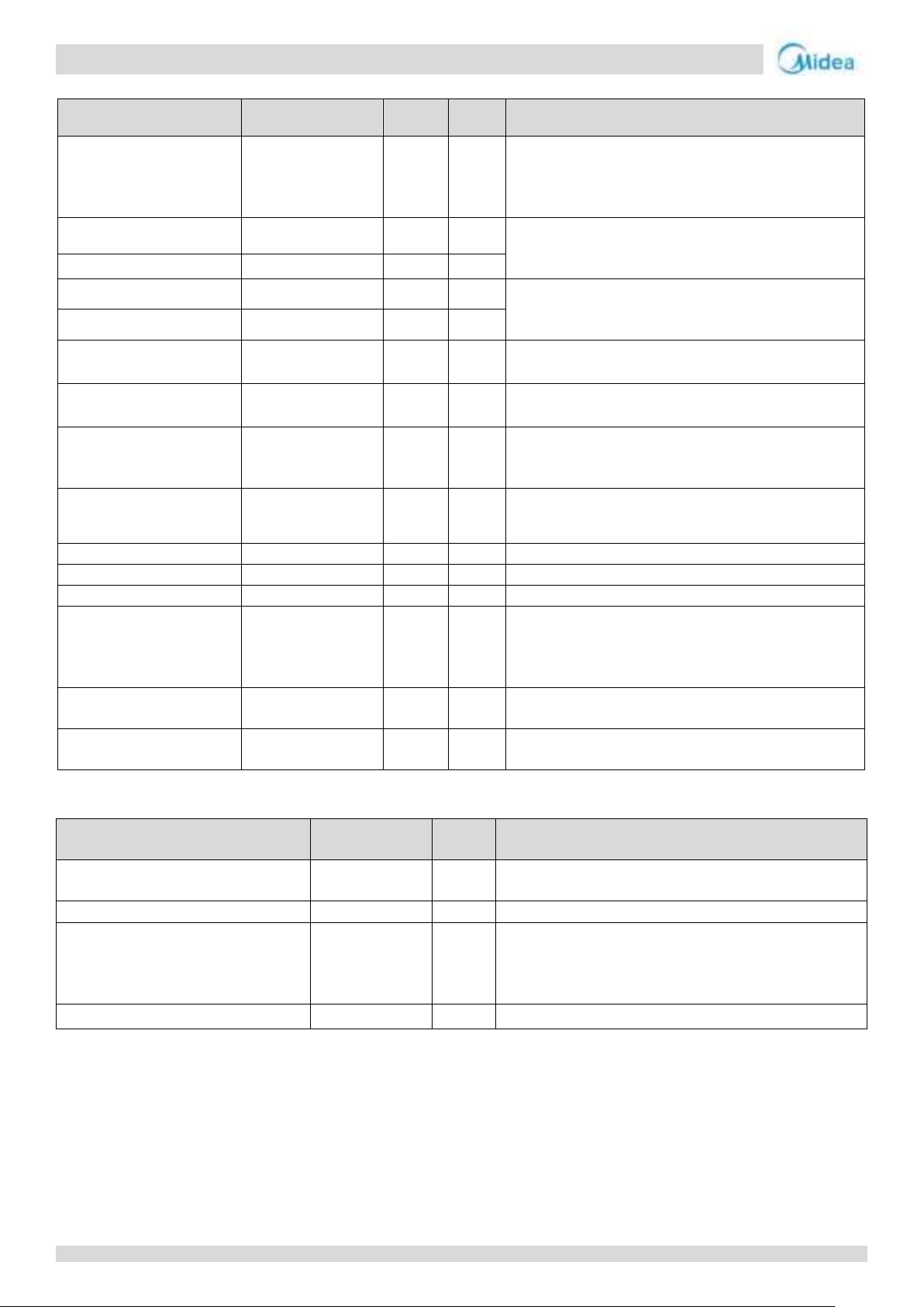
4.3 Startup Control for Cooling Operation
For MC-SU90-RN8L-B:
29
Page 29
Aqua thermal
Midea Aqua thermal Service Manual
Component
Wiring diagram label
75kW
140kW
Control functions and states
Water pump
PUMP
●
●
Non-standard component: After the pump is turned on for 2
minutes, detect the water flow switch continuously. The
compressor can be started only after the water flow is
normal.
Inverter compressor 1
BP1
●
●
Control the outlet water temperature. The operating
increased and decreased frequency is 1Hz/s, and is executed
according to the starting platform.
Inverter compressor 2
BP2
●
●
Inverter fan1
FAN1
●
●
Control According to the exhaust pressure of the outdoor
unit, the initial target windshield is operated for the first
60s, and then correct every 20-60s.
Inverter fan 2
FAN2
●
●
Electronic expansion valve
EXV-A
●
●
Step from 0 to 480. Controlled according to discharge
temperature superheat.
Electronic expansion valve
EXV-B
●
●
Step 480P
Electronic expansion valve
EXV-C
●
●
Step from 0 to 480. Controlled according to temperature
difference between economizer plate heat exchanger inlet
and outlet.
Four-way valve
ST1
●
●
Open
Solenoid valve (defrost)
SV5
●
●
Closed
Solenoid valve (by pass)
SV6
●
●
Open for 600s, then closed.
Solenoid valve (injection)
SV8A/B
●
●
Open
Water flow switch
Water-SW
●
●
After water pump (field supplied) is turned on for 2min, if
water flow switch is open, water pump stops and water flow
error code appears. The compressor can be started after the
water flow is normal.
Water flow switch heater
●
●
Controlled according to ambient temperature, water inlet
temperature and water outlet temperature.
Crank case heater
CCH
● Controlled according to ambient temperature and discharge
temperature.
Component
Wiring diagram
label
180kW
Control functions and states
Inverter compressor
BP1/2
●
Compressor startup program selected according to ambient
temperature1.
DC fan motor
FAN
●
Fan run at maximum speed2.
Electronic expansion valve
EXV
●
Position (steps) from 0 (fully closed) to 480 (fully open),
controlled according to outdoor ambient temperature,
discharge temperature, suction superheat, compressor speed
and refrigerant system pressure.
Four-way valve
ST1
●
Off
For MC-SU75-RN8L-B and MC-SU140-RN8L-B:
For MC-SU180-RN8L-B:
30
Page 30
Aqua thermal
Part 3 - Control
Component
Wiring diagram label
90kW
Control functions and states
Inverter compressor A
BP1
●
Controlled according to load requirement.
Inverter compressor B
BP2
●
DC fan motor A
Fan A
●
Startup after 4-way valve changes refrigerant flow direction.
Controlled according to discharge pressure.
DC fan motor B
Fan B
●
Electronic expansion valve A
EXVA
●
Step from 0 to 480. Controlled according to discharge temperature
superheat.
Electronic expansion valve B
EXVB
●
Step 480
Electronic expansion valve C
EXVC
●
Step from 0 to 480. Controlled according to temperature difference
between economizer plate heat exchanger inlet and outlet.
Four-way valve
ST1
●
On
Solenoid valve (oil balance)
SV4
●
Open for 3min after every 17min.
Solenoid valve (defrost)
SV5
●
Closed
Solenoid valve (by pass)
SV6
●
Closed
Solenoid valve (injection)
SV8A/B
●
Open
Water flow switch
Water-SW
●
After water pump (field supplied) is turned on for 2min, if water
flow switch is open, water pump stops and water flow error code
appears. The compressor can be started after the water flow is
normal.
Electric auxiliary heater
(pipe)
-
●
Controlled according to ambient temperature and total water
outlet temperature.
Crank case heater
c
●
Controlled according to ambient temperature and discharge
temperature.
Component
Wiring
diagram label
75kW
140kW
Control functions and states
Water pump
PUMP
● ● Open
Inverter
compressor 1
BP1
●
●
Control the outlet water temperature. The operating increased and decreased
frequency is 1Hz/s.
Inverter
compressor 2
BP2
●
●
Inverter fan1
FAN1
●
●
Startup after 4-way valve changes refrigerant flow direction. Controlled according
to ambient temperature, discharge pressure and compressor frequency.
Inverter fan 2
FAN2
●
●
Electronic
expansion valve
EXV-A
●
●
Step from 0 to 480. Controlled according to discharge temperature superheat.
Electronic
expansion valve
EXV-B
●
●
Step 480.
Electronic
expansion valve
EXV-C
●
●
Enhanced vapor injection EXV,Step from 0 to 480. Controlled according to
temperature difference between economizer plate heat exchanger inlet and outlet.
Four-way valve
ST1
●
●
Open
Solenoid valve
(defrost)
SV5
●
●
Open during defrost and close at other times.
Solenoid valve (by
pass)
SV6
●
●
Closed
Solenoid valve
(injection)
SV8A/B
●
●
Open
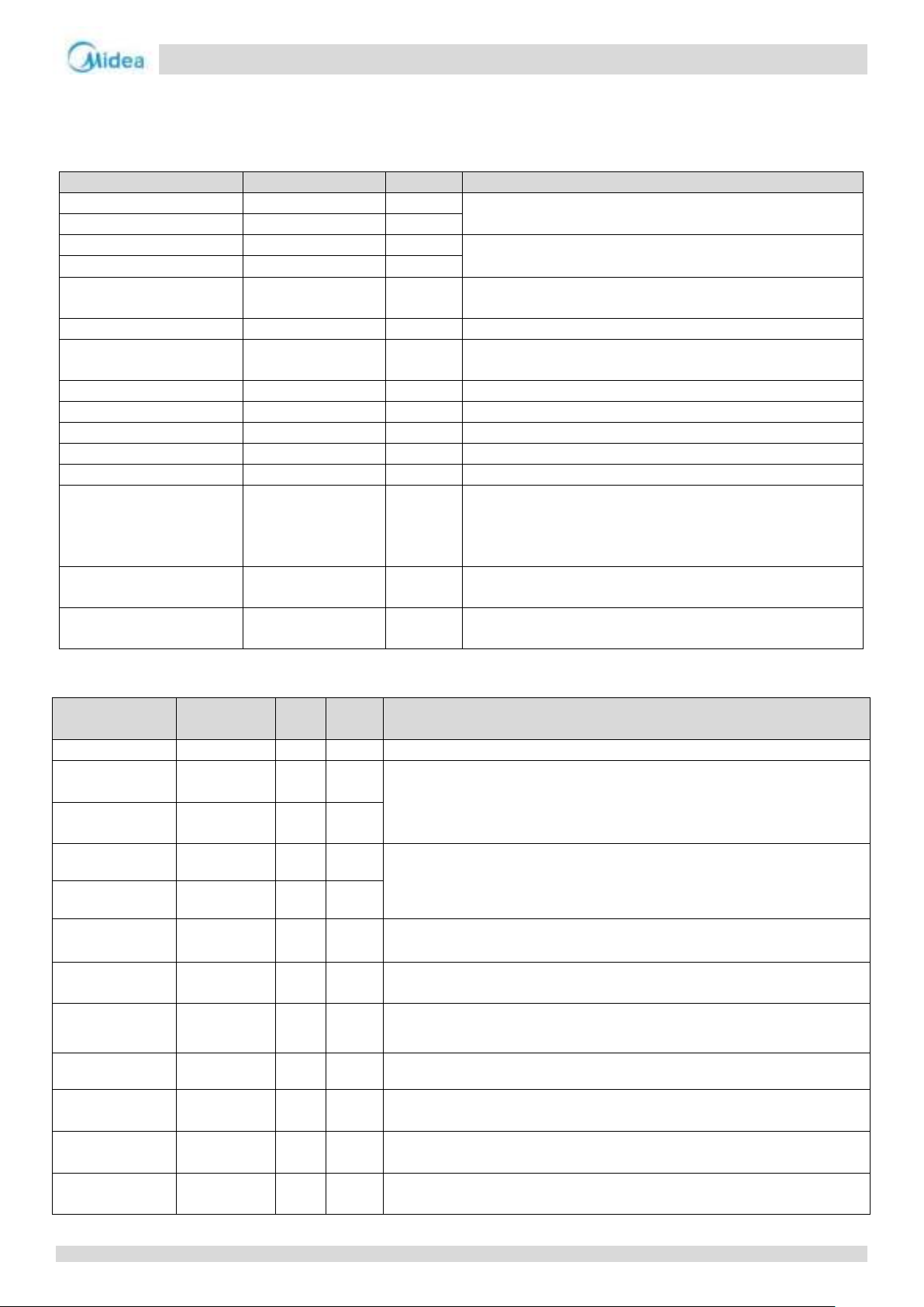
5 Normal Operation Control
5.1 Component Control during heating mode
For MC-SU90-RN8L-B:
For MC-SU75-RN8L-B and MC-SU140-RN8L-B:
31
Page 31
Aqua thermal
Midea Aqua thermal Service Manual
Component
Wiring
diagram
label
180kW
Control functions and states
Inverter
compressor
BP1/2
●
Controlled according to load requirement from hydronic system.
DC fan motor
FAN
●
Controlled according to outdoor heat exchanger pipe temperature.
Electronic
expansion valve
EXV
●
Position (steps) from 0 (fully closed) to 480 (fully open), controlled according to outdoor
ambient temperature, discharge temperature, suction superheat, compressor speed and
refrigerant system pressure.
Four-way valve
ST1
●
On
Component
Wiring diagram label
90kW
Control functions and states
Inverter compressor A
BP1
●
Controlled according to load requirement.
Inverter compressor B
BP2
●
DC fan motor A
Fan A
●
Controlled according to ambient temperature and discharge
pressure and air side heat exchanger refrigerant temperature.
DC fan motor B
Fan B
●
Electronic expansion valve A
EXVA
●
Step 480
Electronic expansion valve B
EXVB
●
Step from 0 to 480. Controlled according to suction temperature
superheat.
Electronic expansion valve C
EXVC
●
Step from 0 to 480. Controlled according to temperature
difference between economizer plate heat exchanger inlet and
outlet.
Four-way valve
ST1
●
Closed
Solenoid valve (oil balance)
SV4
●
Open for 3min after every 17min.
Solenoid valve (defrost)
SV5
●
Closed
Solenoid valve (by pass)
SV6
●
Closed
Solenoid valve (injection)
SV8A/B
●
Open
Water side heat exchanger
heater
-
●
According to water side heat exchanger anti-freezing
temperature.
Water flow switch
Water-SW
●
After water pump (field supplied) is turned on for 2min, if water
flow switch is open, water pump stops and water flow error
code appears. The compressor can be started after the water
flow is normal.
Water flow switch heater
-
●
Controlled according to ambient temperature, water inlet
temperature and water outlet temperature.
Crank case heater
CCH
●
Controlled according to ambient temperature and discharge
temperature.
Component
Wiring diagram label
75kW
140kW
Control functions and states
Inverter compressor 1
BP1
●
●
Control the outlet water temperature. The operating
increased and decreased frequency is 1Hz/s.
Inverter compressor 2
BP2
●
●
Inverter fan1
FAN1
●
●
Control according to the exhaust pressure of the
outdoor unit. Correct every 20-60s, and adjust in
0-32 gears.
Inverter fan 2
FAN2
●
●
Electronic expansion valve
EXV-A
●
●
Step 480.
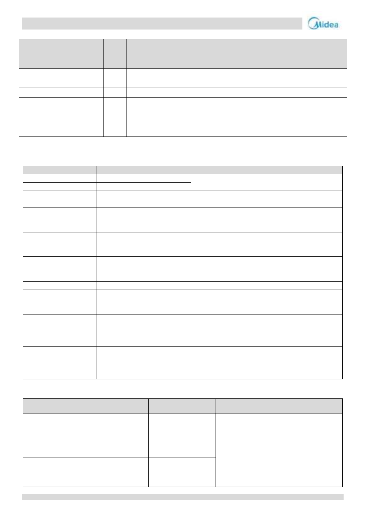
For MC-SU180-RN8L-B:
5.2 Component control during cooling mode
For MC-SU90-RN8L-B:
For MC-SU75-RN8L-B and MC-SU140-RN8L-B:
32
Page 32
Aqua thermal
Part 3 - Control
Electronic expansion valve
EXV-B
●
●
Step from 0 to 480. Controlled according to discharge
temperature superheat.
Electronic expansion valve
EXV-C
●
●
Enhanced vapor injection EXV, Step from 0 to 480.
Controlled according to temperature difference
between economizer plate heat exchanger inlet and
outlet.
Four-way valve
ST1
●
●
Closed
Solenoid valve (defrost)
SV5
●
●
Closed
Solenoid valve (by pass)
SV6
●
●
Closed
Solenoid valve (injection)
SV8A/B
●
●
Open
Water side heat exchanger
heater
-
●
●
According to water side heat exchanger anti-freezing
temperature
Water flow switch
Water-SW
●
●
After water pump (field supplied) is turned on for
2min, if water flow switch is open, water pump stops
and water flow error code appears. The compressor
can be started after the water flow is normal.
Water flow switch heater
-
●
●
Controlled according to ambient temperature, water
inlet temperature and water outlet temperature
Crank case heater
CCH
●
●
Controlled according to ambient temperature and
discharge temperature
Component
Wiring diagram label
180kW
Control functions and states
Inverter compressor
BP1/2
●
Controlled according to load requirement from hydronic system.
DC fan motor
FAN
●
Controlled according to outdoor heat exchanger pipe temperature.
Electronic expansion valve
EXV
●
Position (steps) from 0 (fully closed) to 480 (fully open), controlled
according to outdoor ambient temperature, discharge
temperature, suction superheat, compressor speed and refrigerant
system pressure.
Four-way valve
ST1
●
Off
For MC-SU180-RN8L-B:
5.3 Compressor Output Control
The compressor rotation speed is controlled according to the load requirement. Before compressor startup, the outdoor unit
determines the compressor target speed according to outdoor ambient temperature, discharge temperature and then runs the
appropriate compressor startup program. Once the startup program is complete, the compressor runs at the target rotation
speed.
The compressor speed is controlled according to two parts in normal operation:
In cooling mode: In a single system, the compressor speed is controlled according to the water outlet temperature and water
outlet setting temperature. In a combination system, the compressor of master unit is controlled according total water outlet
temperature and water outlet setting temperature, the compressor of the slave unit is controlled according to water inlet and
water outlet temperature. Both in a single system and combination system, the compressor speed is limited by the inverter
module temperature (calculated value), ambient temperature, discharge temperature, discharge pressure and air side heat
exchanger refrigerant total outlet temperature.
33
Page 33
Aqua thermal
Midea Aqua thermal Service Manual
Fan speed index
Fan speed (rpm)
FAN A
FAN B 0 0
0
1
150
0
2
190 0 3
230
0
4
270 0 5
330 0 6
150
150
7
170
170
8
190
190 9 210
210
10
230
230
11
250
250
12
270
270
13
290
290
14
310
310
15
330
330
16
350
350
17
370
370
18
400
400
19
430
430
20
450
450
21
470
470
22
510
510
23
550
550
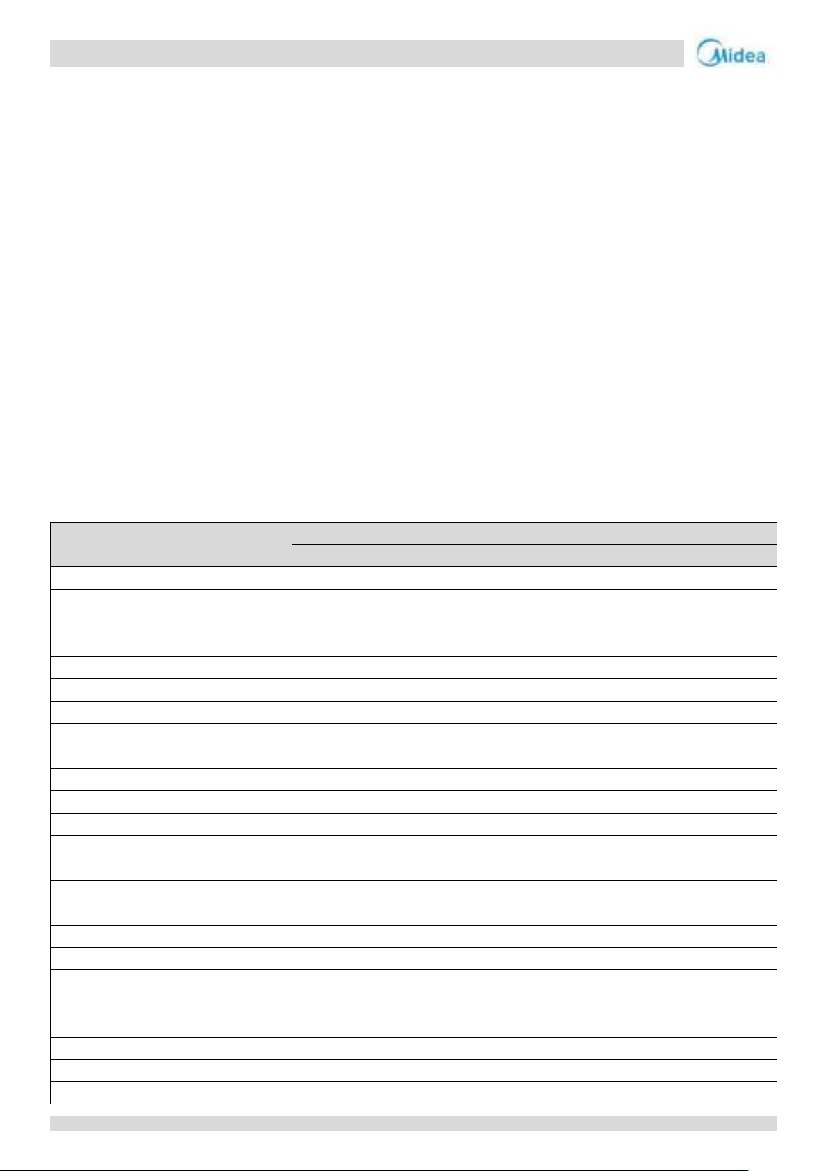
5.4 Compressor Step Control
The running speed of six-pole compressors in rotations per second (rps) is one third of the frequency (in Hz) of the electrical
input to the compressor motor. The frequency of the electrical input to the compressor motors can be altered at a rate of 1Hz in
two seconds.
5.5 Four-way Valve Control
The four-way valve is used to change the direction of refrigerant flow through the water side heat exchanger in order to switch
between cooling and heating operations. During heating operation, the four-way valve is on; during cooling and defrosting
operation, the four-way valve is off.
5.6 Electronic Expansion Valve Control
Power-on self-test:
When the power is first turned on, the EXV is closed for 700 steps, proofreading the 0-step position, and re-opening at a
maximum of 480.
Startup:
Adjust from 480 to the initial position, (the initial opening is determined by the ambient temperature), maintain for a
period of time. EXV is controlled according to suction superheat, exhaust, and compressor speed.
When the outdoor unit is in standby:
The EXV is at position 480 (steps).
When the outdoor unit stops:
After the compressor shuts down for 1 minute, the EXV is fully closed first, and then opened to the initial position.
5.7 Outdoor Fan Control
For MC-SU75-RN8L-B:
34
Page 34
Aqua thermal
Part 3 - Control
24
580
580
25
610
610
26
640
640
27
680
680
28
710
710
29
750
750
30
780
780
31
800
800
32
830
830
Fan speed index
Fan speed (rpm)
FAN A
FAN B
0 0 0
1
150
0
2
190 0 3
230 0 4
270
0
5
330 0 6
150
150 7 170
150 8 170
150 9 190
170
10
210
190
11
230
210
12
250
230
13
270
250
14
290
270
15
310
290
16
330
310
17
350
330
18
370
350
19
400
370
20
430
400
21
450
430
22
480
460
23
500
480
24
520
500
25
540
520
26
560
540
27
560
540
28
580
560
29
580
560
30
600
580
31
600
580
32
620
600
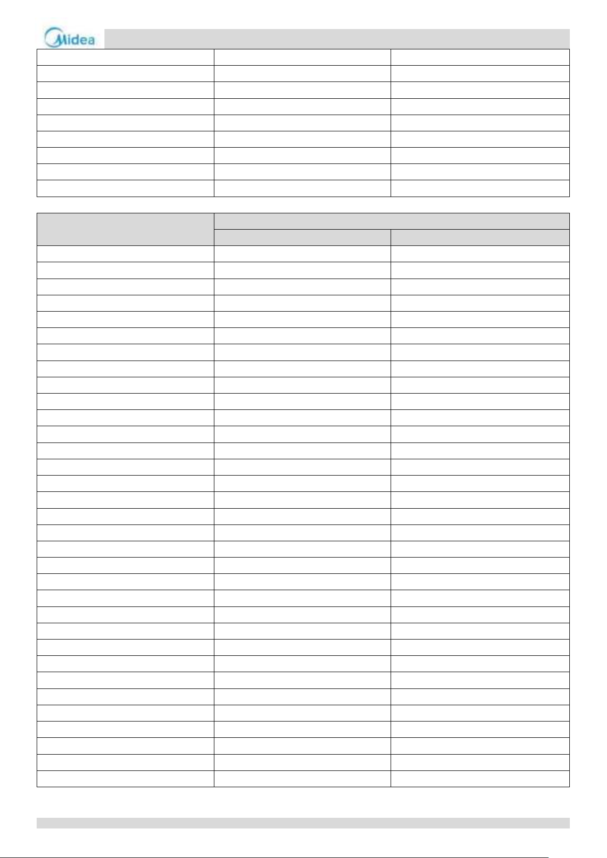
For MC-SU90-RN8L-B and MC-SU180-RN8L-B:
35
Page 35
Aqua thermal
Midea Aqua thermal Service Manual
Fan speed index
Fan speed (rpm)
FAN A
FAN B 0 0
0
1
150 0 2
190 0 3
230
0
4
270
0
5
330
0
6
150
150
7
170
170
8
170
170 9 190
190
10
210
210
11
230
230
12
250
250
13
270
270
14
290
290
15
310
310
16
330
330
17
350
350
18
370
370
19
400
400
20
430
430
21
470
470
22
510
510
23
550
550
24
600
600
25
650
650
26
680
680
27
700
700
28
720
720
29
750
750
30
780
780
31
800
800
32
830
830
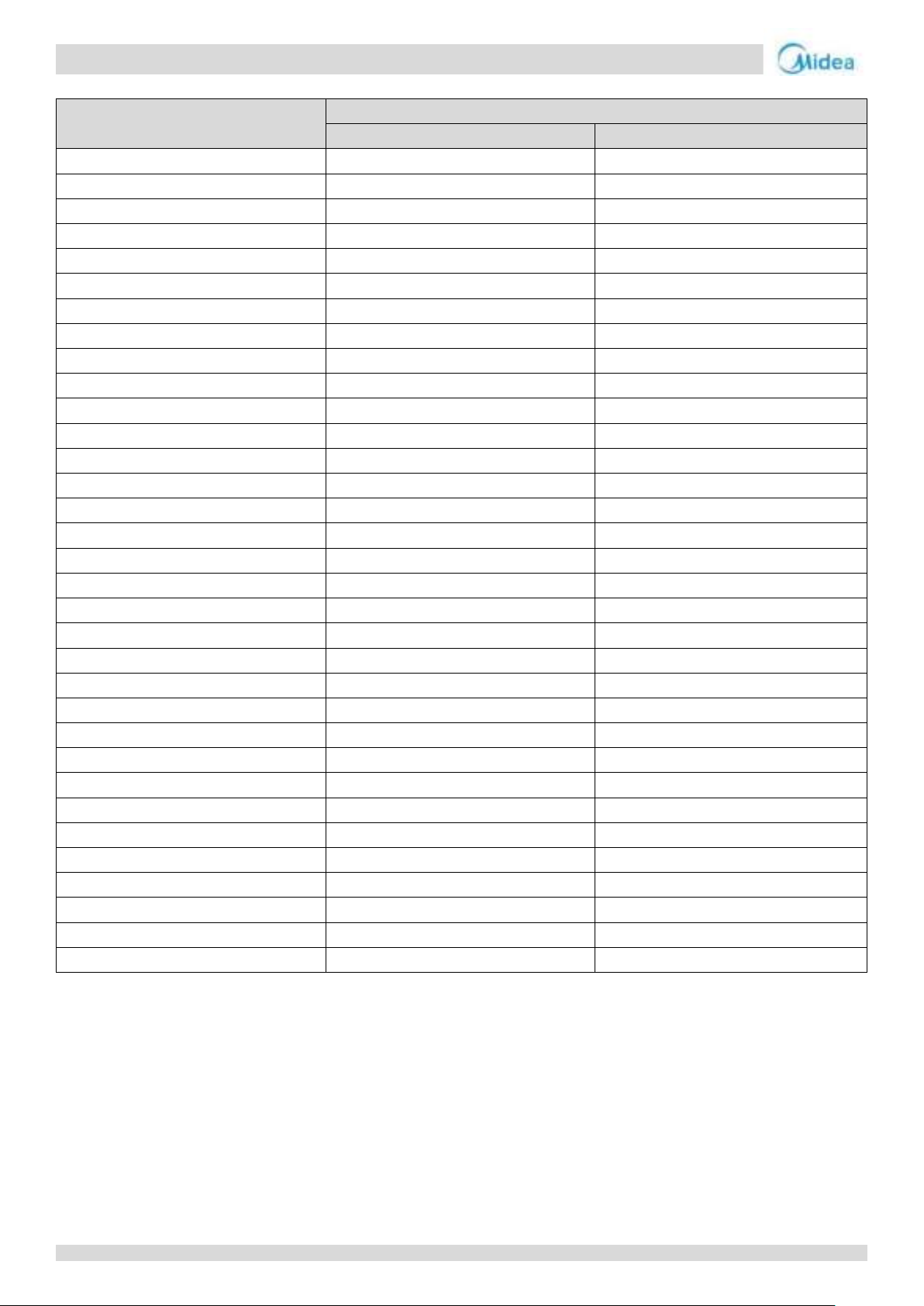
For MC-SU140-RN8L-B:
36
Page 36
Aqua thermal
Part 3 - Control
Notes:
1. P
c
: Discharge pressure
Notes:
1. P
e
: Suction pressure
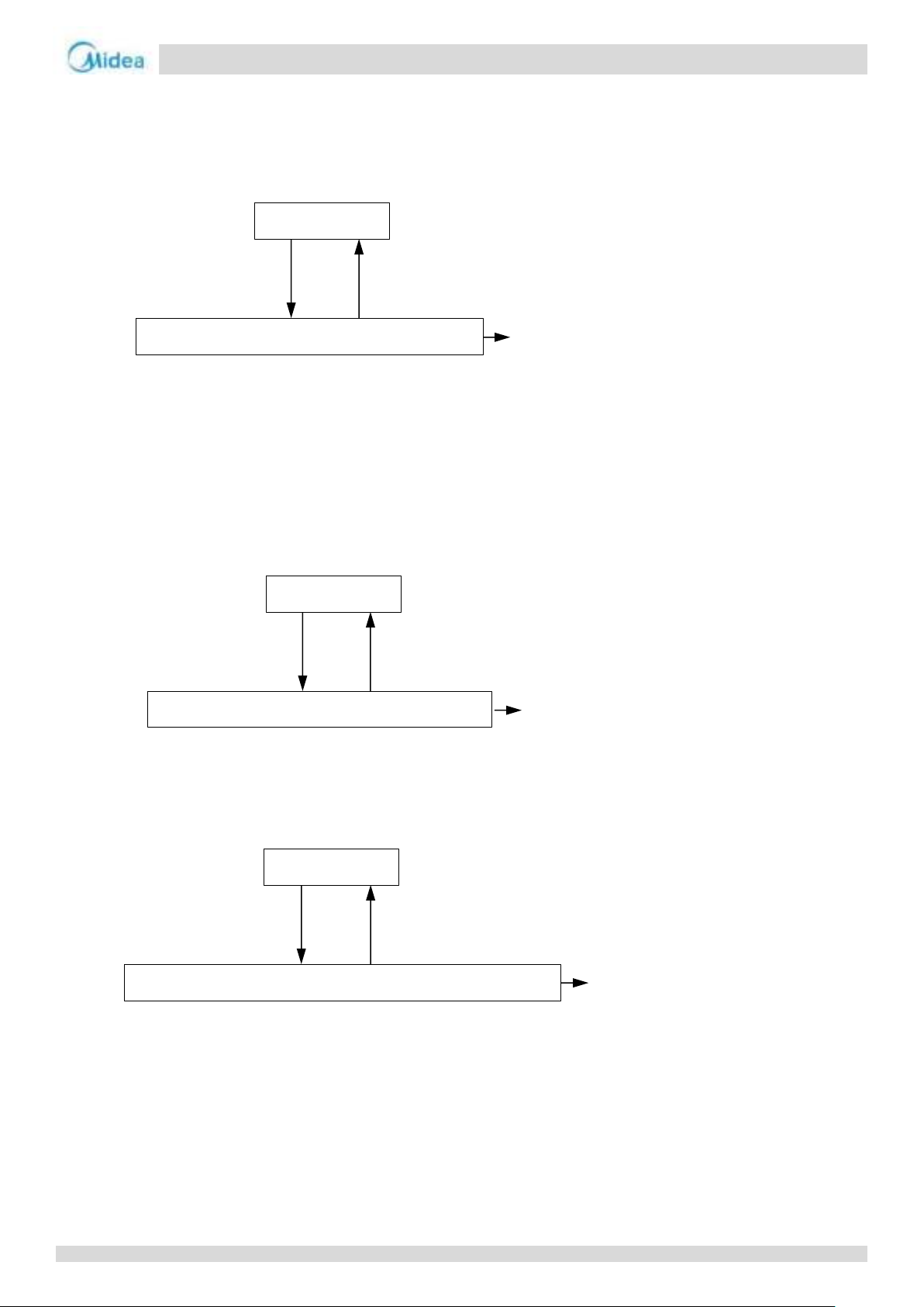
Pc > 4.2MPa
Pc < 3.2MPa
Normal operation
High pressure protection, error code P0 is displayed
When P0 protection occurs 3 times in
60 minutes, a manual system restart is
required before the system can
resume operation.
Pe < 0.05MPa
Pe > 0.15MPa
Normal operation
Low pressure protection, error code P1 is displayed
When P1 protection occurs 3 times in
60 minutes, a manual system restart is
required before the system can
resume operation.
Discharge temperature > 115°C
Discharge temperature < 90°C
Normal operation
High discharge temperature protection, error code P0 is displayed
When P0 protection occurs 3 times in
60 minutes, a manual system restart is
required before the system can
resume operation.
6 Protection Control
6.1 High Pressure Protection Control
This control protects the refrigerant system from abnormally high pressure and protects the compressor from transient spikes in
pressure.
When the discharge pressure rises above 4.2MPa the system displays P0 protection and the faulty unit stops running. When the
discharge pressure drops below 3.2MPa, the compressor enters re-start control.
6.2 Low Pressure Protection Control
This control protects the refrigerant system from abnormally low pressure and protects the compressor from transient drops in
pressure.
6.3 Discharge Temperature Protection Control
This control protects the compressor from abnormally high temperatures and transient spikes in temperature.
When the discharge temperature rises above 115°C the system displays P0 protection and the faulty unit stops running. When
the discharge temperature drops below 90°C, the compressor enters re-start control.
37
Page 37
Aqua thermal
Midea Aqua thermal Service Manual
Notes:
1. P4 is the protection for System A, P5 is the protection for System B.
Notes:
1. P4 is the protection for System A, P5 is the protection for System B.
Notes:
1. The module temperature is calculated by inverter module.
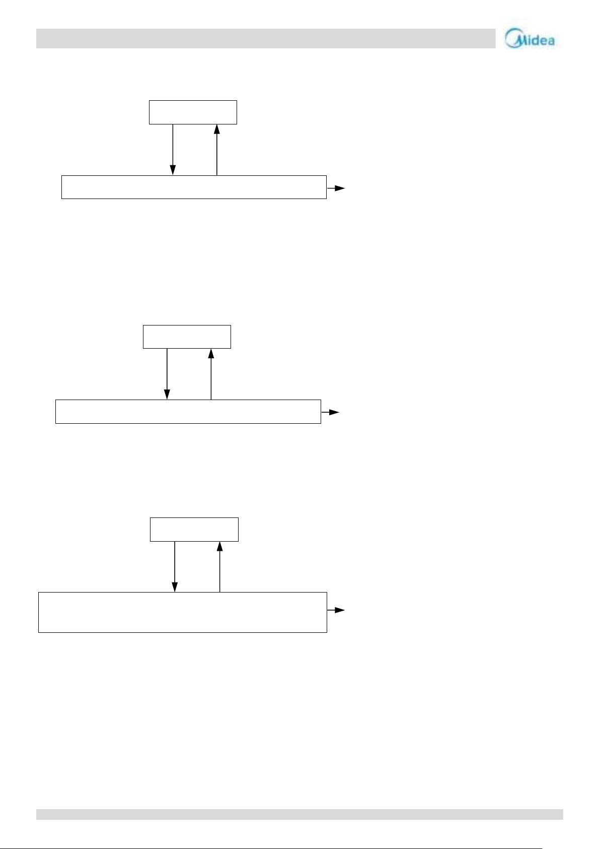
Current > protection current
Current < protection current
Normal operation
Compressor current protection, error code P4/P5 is displayed
Current > protection current
Current < protection current
Normal operation
Compressor current protection, error code P4/P5 is displayed
Module temperature1> 100°C
Module temperature1< 70°C
Normal operation
Inverter module temperature protection, error code PL is
displayed
When P4 or P5 protection occurs 3
times in 60 minutes, a manual system
restart is required before the system
can resume operation.
CL is displayed when PL error occurs 3
times in 100 minutes, a manual
system restart is required before the
system can resume operation.
When P4 or P5 protection occurs 3
times in 60 minutes, a manual system
restart is required before the system
can resume operation.
6.4 Compressor and Inverter Module Protection Control
For MC-SU75-RN8L-B and MC-SU140-RN8L-B:
The inverter module board protection current of a single compressor: AC is 53A, bus DC current is 232A.
For MC-SU90-RN8L-B and MC-SU180-RN8L-B:
The inverter module board protection current of a single compressor: AC is 60A, bus DC current is 140A.
This control protects the compressors from abnormally high currents and protects the inverter modules from abnormally high
temperatures. It is performed for each compressor and inverter module.
When the compressor current rises above protection current, the system displays P4 or P5 protection and the faulty unit stops
running. When the compressor current drops below protection current, the compressor enters re-start control.
When the module temperature rises above 100°C, the system displays PL protection and all the units stop running. When the module temperature drops below
70°C, the compressor enters re-start control.
38
Page 38
Aqua thermal
Part 3 - Control
Note:
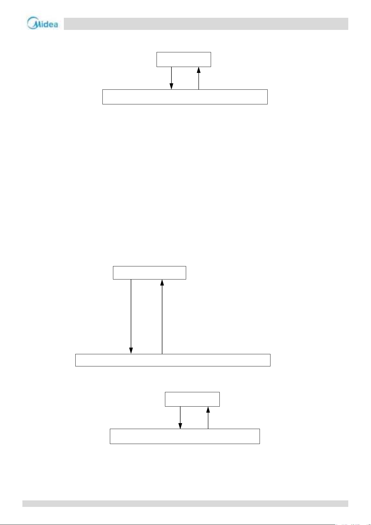
1. T3: Air side heat exchanger refrigerant outlet temperature
Voltage ≥ 265V
or Voltage ≤ 170V
Voltage < 250V
or Voltage ≥ 180V
Normal operation
Compressor voltage protection, error code H5 is displayed
For normal cooling mode:
Min (Tw/Two/Twi/Taf2) ≤ 4°C for 5s
For low leaving water temperature
Min (Tw/Two/Twi/Taf2) ≤ -1°C for 5s
Any of the following satisfies then recover
°C before compressor runs(judged by
°C and compressor running time
Min(T5/Taf1) ≤ 4°C and compressor running time
≥30min(judged by master unit for single pump control; judged
Normal operation
Anti-freeze protection, error code Pb is displayed; unit runs heating mode
T3 > 62°C
T3 < 55°C
Normal operation
High temperature protection, error code P7 is displayed
6.5 Voltage Protection Control
This control protects the units from abnormally high or abnormally low voltages.
When the phase voltage of AC power supply is at or above 265V for more than 30 seconds, the system displays H5 protection
and the faulty unit stops running. When the phase voltage drops below 250V for more than 30 seconds, the unit restart once the
compressor re-start delay has elapsed. When the phase voltage is below 170V for more than 30 seconds, the system displays H5
protection and all the units stop running. When the AC voltage rises to at or above 180V for more than 30 seconds, the
refrigerant system restarts once the compressor re-start delay has elapsed.
6.6 DC Fan Motor Protection Control
This control protects the DC fan motors from abnormal power supply. DC fan motor protection occurs when the fan module does
not receive any feedback from the fan motor.
When DC fan motor protection control occurs the system displays the PU error code and the faulty unit stops running. When PU
protection occurs 10 times in 120 minutes, the FF error is displayed. When an FF error occurs, a manual system restart is
required before the system can resume operation.
6.7 Water Side Heat Exchanger Anti-freeze Protection Control
When water side heat exchanger anti-freeze protection occurs the system displays error code Pb and the unit enters
anti-freezing mode.
1. Min(Tw/Two/Twi/Taf2) ≥8
master unit)
cooling mode:
2. Min(Tw/Two/Twi/Taf2) ≥15
≥5min (judged by master unit)
3.
by each unit for multiple pumps control)
6.8 Air Side Heat Exchanger High Temperature Protection Control
This control protects the air side heat exchanger from high temperature.
When the air side heat exchanger refrigerant outlet temperature (T3) rises above 62°C, the system displays P7 protection and the
faulty unit stops running. When the air side heat exchanger refrigerant outlet temperature (T3) drops below 55°C, the
compressor enters re-start control.
39
Page 39
Aqua thermal
Midea Aqua thermal Service Manual
Notes:
1. Twi: Water side heat exchanger inlet temperature;
2. Two: Water side heat exchanger outlet temperature.
Notes:
1. Taf2: Water side heat exchanger anti-freezing temperature 2
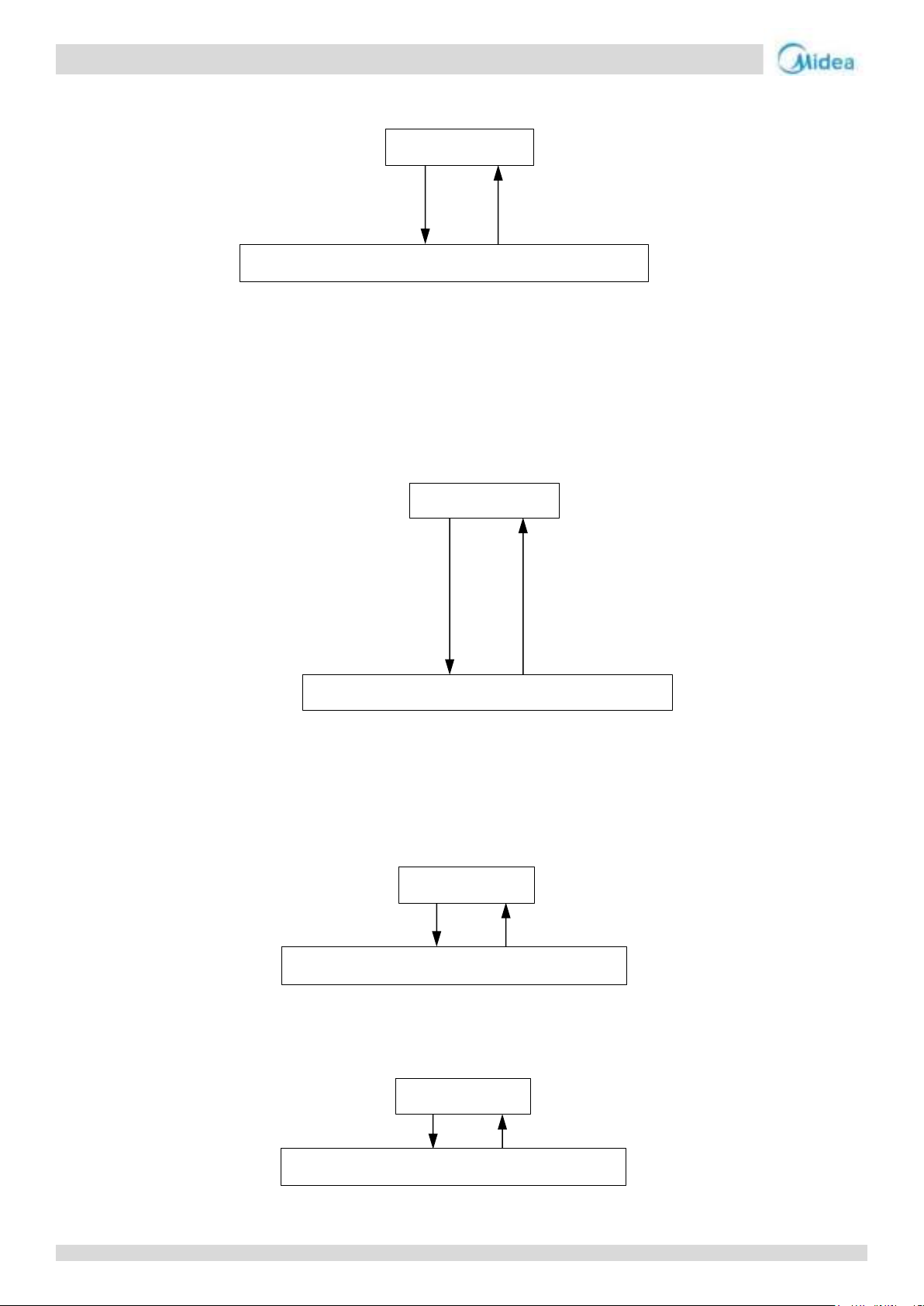
∣Twi-Two∣≥ 10°C
∣Twi-Two∣≤ 6°C
Normal operation
Temperature difference protection, error code P9 is displayed
For normal cooling mode:
For normal cooling mode:
Normal operation
Low temperature protection, error code PE is displayed
0.5Mpa≤ Pe < 0.6Mpa for 30s
Or Pe < 0.5Mpa for 5s
Unit stops
Normal operation
Low pressure protection, error code PC is displayed
Pe < 0.4Mpa for 30s
Unit stops
Normal operation
Low pressure protection, error code PC is
6.9 Water Side Heat Exchanger Temperature Difference Protection Control
When the temperature difference rises at or above 10°C, the system displays P9 protection and the faulty unit stops running.
When the temperature difference drops below 6°C, the compressor enters re-start control.
6.10 Water Side Heat Exchanger Low Temperature Protection Control
This control protects the water side heat exchanger from ice formation.
Taf2 ≤ 3°C for 3s
For low leaving water temperature mode:
Taf2 ≤ -2°C for 3s
Taf2 > 10°C and unit stops time >3min
For low water outlet cooling mode:
Taf2 > 5°C and unit stops time >7min
6.11 Water Side Heat Exchanger Low Pressure Protection Control
This control protects the water side heat exchanger from ice formation.
Normal cooling mode
In normal cooling mode, when 0.5Mpa≤ Pe < 0.6Mpa for 30s or Pe < 0.5Mpa for 5s, the system displays PC protection and the
faulty unit stops running. When the unit stop, the compressor enters re-start control.
Low leaving water temperature mode
In low water temperature cooling mode, when the suction pressure drops below 0.4Mpa for 30s, the system displays PC
protection and the faulty unit stops running. When the unit stop, the compressor enters re-start control.
40
Page 40
Aqua thermal
Part 3 - Control
… …
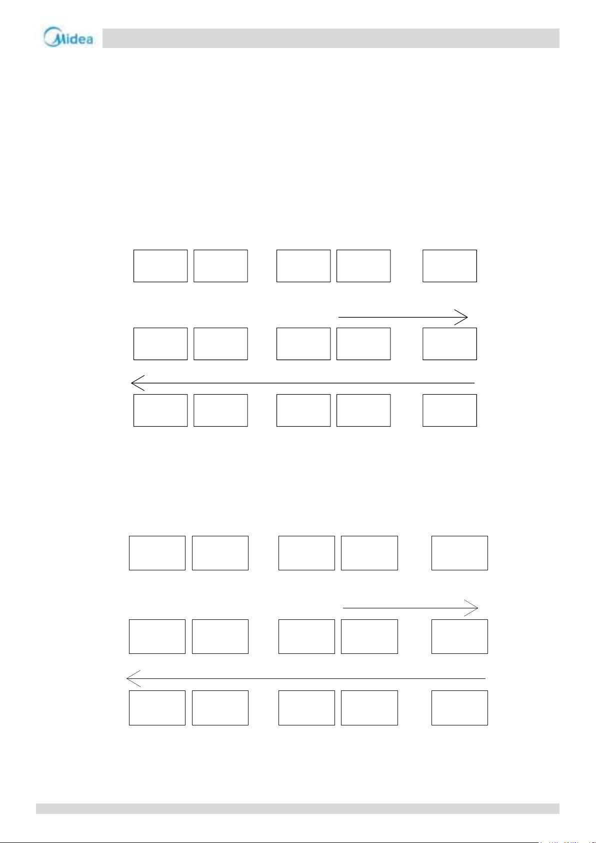
1 2 8 9 16
Startup Startup Startup
Startup
… …
Running Running Running
Loading
… …
Offloading
Loading in sequence (from 9 to 16)
Offloading in sequence (from 16 to 1)
1 2 8 9 16
1 2 8 9 16
… …
16 15 9 8 1
Startup Startup Startup
Startup
… …
Running Running Running
Loading
… …
Offloading
Loading in sequence (from 8 to 1)
Offloading in sequence (from 1 to 16)
16 15 9 8 1
16 15 9 8 1
7 Special Control
7.1 Outdoor Unit Duty Cycling
In systems with multiple outdoor units, outdoor unit duty cycling is used to balance the compressor running time. Outdoor unit
duty cycling occurs whenever all the outdoor units stop running (either because the leaving water set temperature has been
reached or because a master unit error has occurred):
Take 16 units in parallel as an example:
First cycle:
When the outdoor units are powered on for the first time, if there is a load requirement, 50% of the units turn on starting
with the 0# master unit to higher address slave units. As the leaving water temperature approaches its set temperature, units
shut down in succession, starting with the unit with the highest address.
Second cycle:
The next time a load requirement exists (or following a master unit error), the units turn on starting with the highest
address unit to lower address units. As the leaving water temperature approaches its set temperature, units shut down in
succession, starting with the unit with the lowest address.
Subsequent cycles will repeat the actions of the first and second cycles
Notes:
1. The address settings on the outdoor unit main PCBs for master unit and slave unit do not change.
41
Page 41
Aqua thermal
Midea Aqua thermal Service Manual
Component
Wiring diagram
label
4-10kW
Control functions and states
Inverter compressor
COMP
●
Runs at defrosting operation rotation speed
DC fan motor
FAN
●
Off
Electronic expansion valve
EXV
●
Fully open
Four-way valve
4-WAY
●
Off
0# electric
control box
“TEMP-SWITCH” port
Power (DC 12V)
Main control board is provided
0# electric
control box
“TEMP-SWITCH” port
Power (DC 12V)
Main control board is provided
7.2 Defrosting Operation
In order to recover heating capacity, the defrosting operation is conducted when the outdoor unit air side heat exchanger is
performing as a condenser. The defrosting operation is controlled according to outdoor ambient temperature, air side heat
exchanger refrigerant temperature, water inlet temperature, compressor running time and defrosting time.
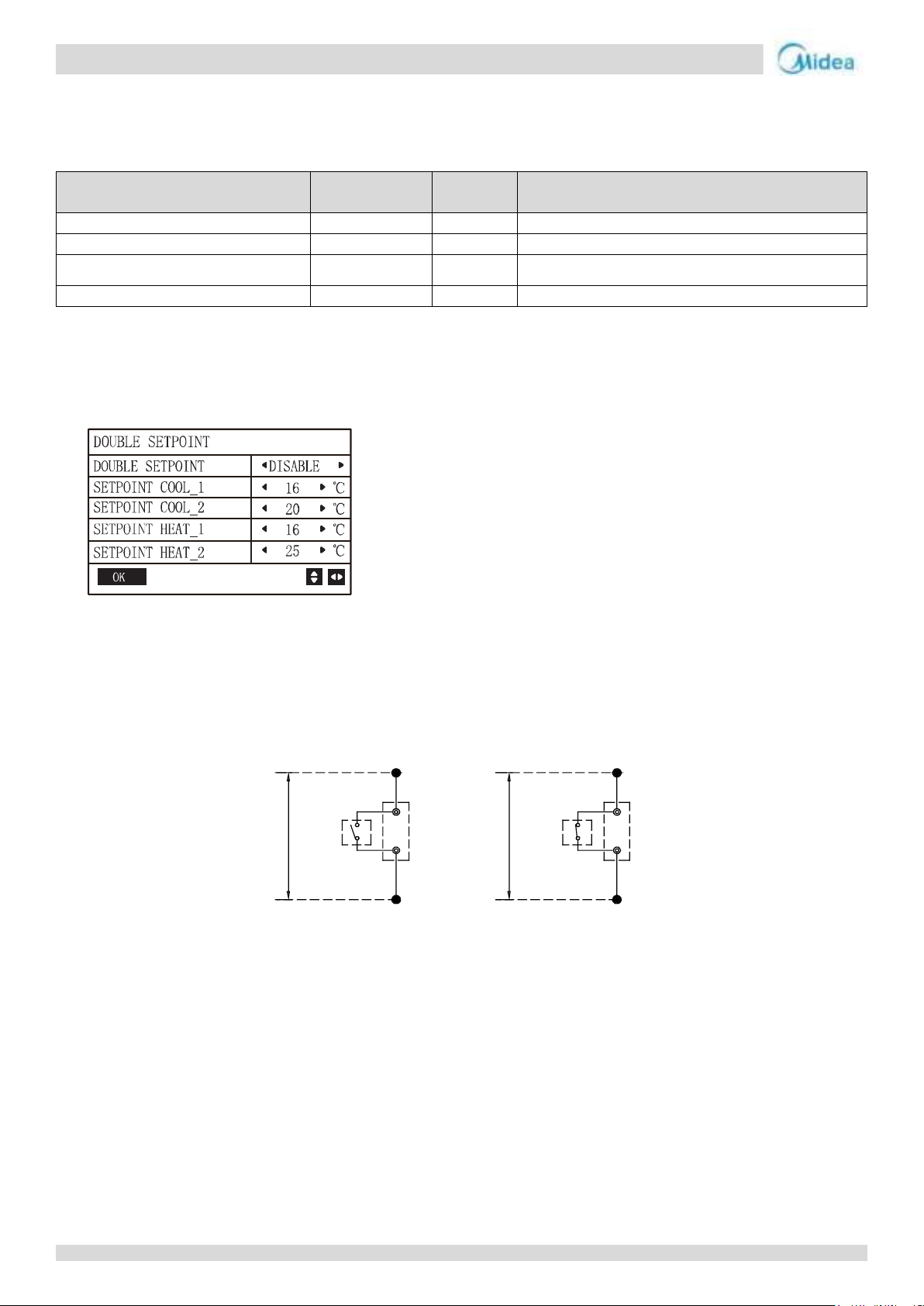
7.3 TEMP-SWITCH control
The function of “TEMP-SWITCH” must be set by wired controller for two target water temperature. For cooling and heating mode,
different water temperatures can be switched just by one-touch. The operation method is as follows:
Setting: “USER MENU”——“DOUBLE SETPOINT”
Wire connection: Shorting the terminal block CN110 at slave board (Refer to the Part 4, 3.1 Single unit) for
MC-SU75-RN8L-B and MC-SU140-RN8L-B.Connect a switch between 20 and 25 terminals of block XT2 (Refer to the Part 4,
3.1 Single unit) for MC-SU90-RN8L-B and MC-SU180-RN8L-B.If the switch is off, unit operates at first target water
temperature. If the switch is on unit operates at second target water temperature.
42
Page 42

Aqua thermal
Part 4 - Diagnosis and Troubleshooting
Part 4
Diagnosis and
Troubleshooting
1 Electric Control Box Layout ....................................................................... 44
2 PCB Introduction ...................................................................................... 46
3 Wiring diagram ........................................................................................ 61
4 Error Code Table ....................................................................................... 68
5 Troubleshooting ....................................................................................... 70
6 Drive Module Failure .............................................................................. 141
7 Appendix ................................................................................................ 154
43
Page 43
Aqua thermal
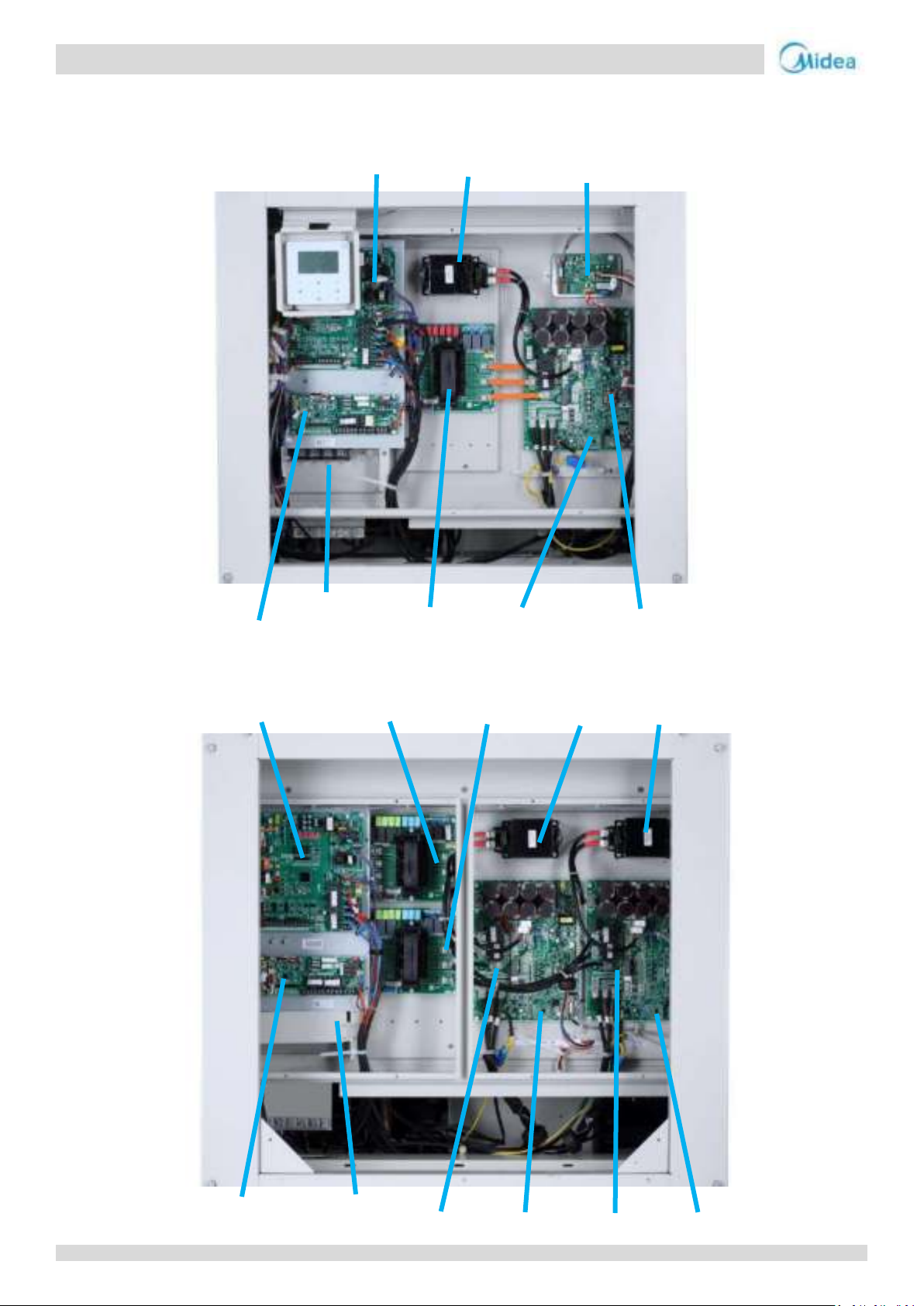
Midea Aqua thermal Service Manual
Compressor inverter module
PED board
Main power supply
wiring set
Expanding board
Main control board
AC filter board
Inductor
Fan module A
Fan module A
PED board A
Fan module B
PED board B
Main power supply
wiring set
Expanding board
Mian control board
AC Filter board A
Inductor A
Inductor B
AC Filter board B
Fan module board (Fan B)
Module components (Compressor + Fan A)
1 Electric Control Box Layout
For MC-SU75-RN8L-B
For MC-SU140-RN8L-B
44
Page 44
Aqua thermal
Part 4 - Diagnosis and Troubleshooting
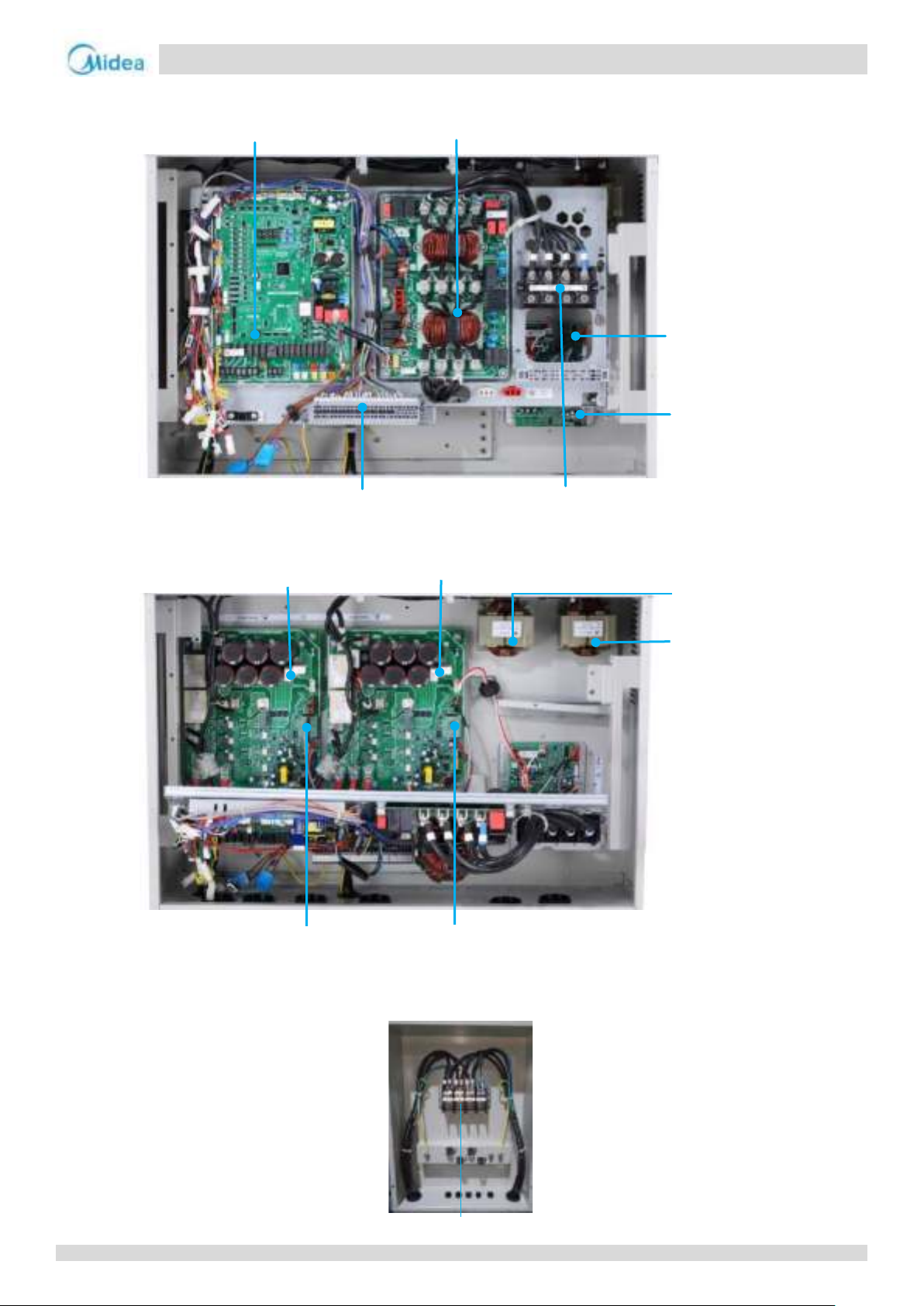
Electric control box side view-upper layer
Main control board
AC filter board
Fan module A
Fan module B
Connection terminal
Power supply
Electric control box side view-bottom layer
Compressor Inverter module A
Compressor Inverter module B
Reactor
Reactor
PED board PED board
Midea electric control side view
Power supply
For MC-SU90-RN8L-B and MC-SU180-RN8L-B
For MC-SU180-RN8L-B only
45
Page 45
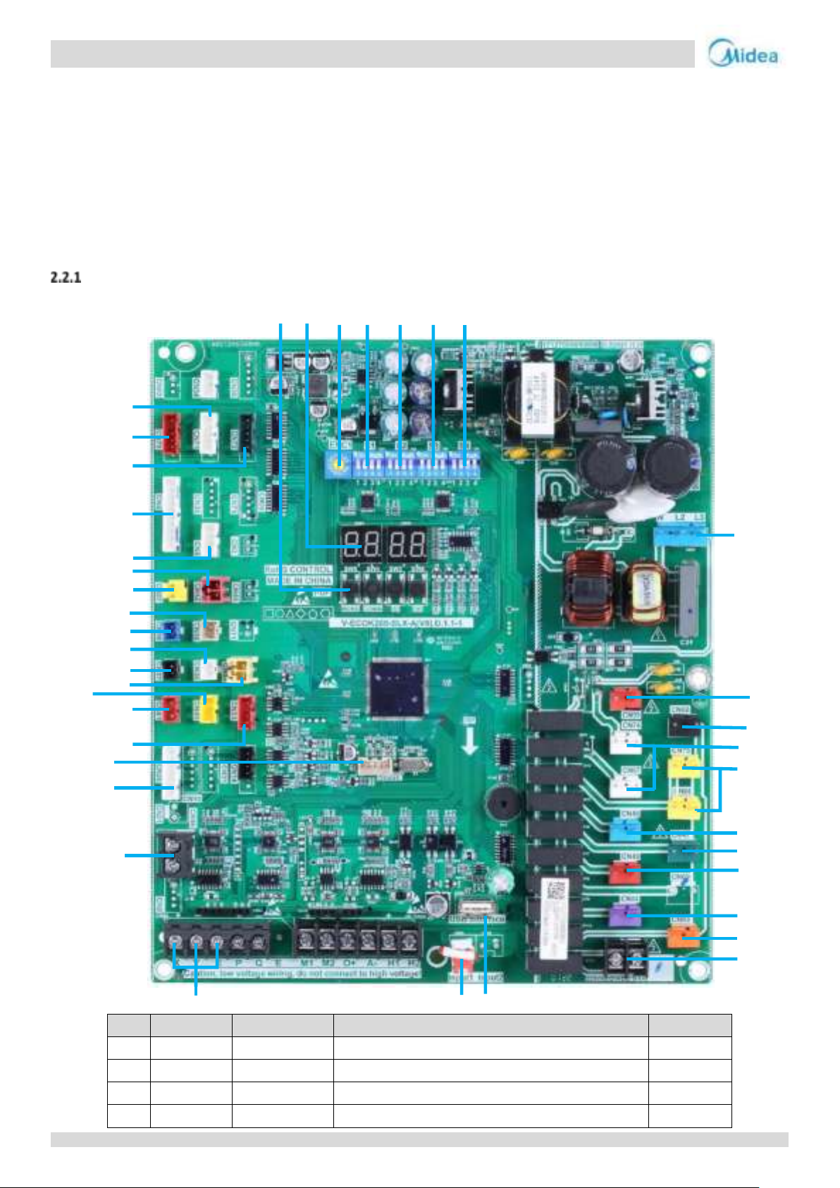
Aqua thermal
Midea Aqua thermal Service Manual
Label
Code
Port
Explanation
Voltage
1
CN32
POWER
Power supply port
220-240V
2
CN99
Expanding board power connector
220-240V
3
CN68
PUMP
Pump contactor control port (connected in factory)
220-240V
4
CN74/CN67
CCH
compressor heating belt
220-240V
1
2
3
4
5
6
7
8
9
10
11
1213
14
15
16
17
18
19
20
21
22
23
24
25
26
27
28
29
30
31
32
33
34
35
36
37
38
39
2 PCB Introduction
2.1 Types
Aqua thermal 75kW, 90kW and 140kW unit have one main control board, two compressor inverter module board, two DC fan
inverter module board and one filter board.
Aqua thermal 180kw unit have two main control board, four compressor inverter module board, four DC fan inverter module
board and two filter board.
2.2 Main PCB
Main PCB component
For MC-SU75-RN8L-B and MC-SU140-RN8L-B
46
Page 46
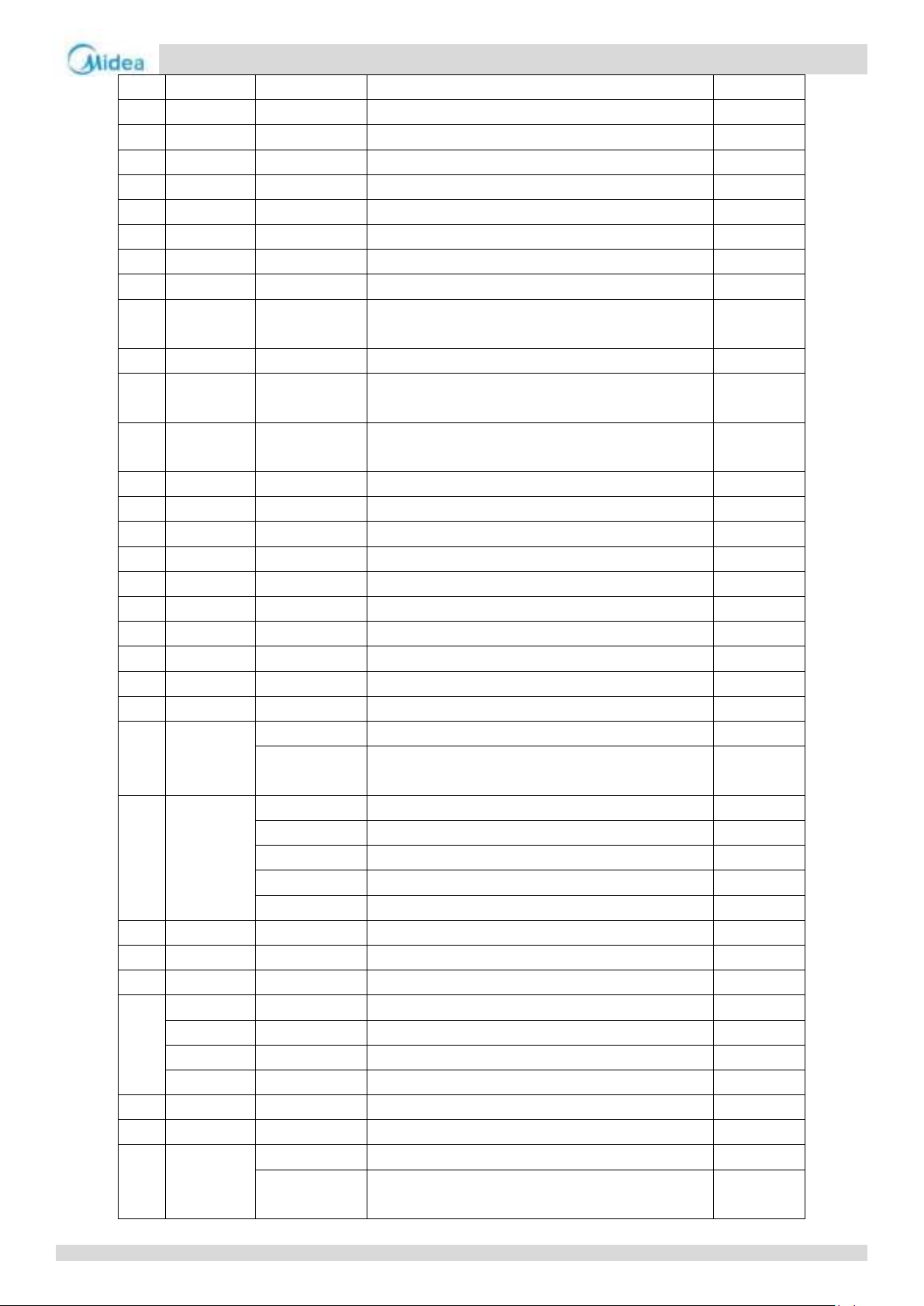
Aqua thermal
Part 4 - Diagnosis and Troubleshooting
5
CN75/CN66
EVA-HEAT
Plate heat exchanger electric heating belt
220-240V
6
CN48
ST1
Four-way valve
220-240V
7
CN47
SV6
One-way solenoid valve
220-240V
8
CN49
SV5
One-way solenoid valve
220-240V
9
CN84
SV8A
One-way solenoid valve
220-240V
10
CN83
SV8B
One-way solenoid valve
220-240V
11
CN93
ALARM
Fault alarm port
/
12
CN65
USB
USB program burning port
DC5V
13
CN28
PH-PRO
Three-phase protector signal detection port
DC12V
14
CN22
XYE
External unit parallel connection communication port &
external unit and wired controller communication port
DC5V
15
CN46
Wired controller power supply port
DC12V
16
CN26
O-Motor
Module board PTC relay control port/Module board
communication port
DC12V/DC5V
17
CN300
DEBUG
Main control program burn port(WizPro200RS
programmer)
DC3.3V
18
CN33
MS
Expanding board communication port
DC12V/DC5V
19
CN41
Low pressure sensor
DC3.3V
20
CN40
High pressure sensor
DC3.3V
21
CN45
Taf2
Water side antifreeze temperature sensor
DC3.3V
22
CN37
T3A
Pipe temperature sensor of the condenser
DC3.3V
23
CN30
T4
Outdoor ambient temperature sensor
DC3.3V
24
CN16
T3B
Pipe temperature sensor of the condenser
DC3.3V
25
CN38
TP2
DC inverter compressor B discharge temperature sensor
DC3.3V
26
CN27
TP-PRO
Discharge temperature controller
DC3.3V
27
CN42
L-PRO
Low pressure switch
DC3.3V
28
CN8
T6A
Refrigerant inlet temperature of EVI plate heat exchanger
DC3.3V
T6B
Refrigerant outlet temperature of EVI plate heat
exchanger
DC3.3V
29
CN4
Twi
Unit water inlet temperature sensor
DC3.3V
Th
System suction temperature sensor
DC3.3V
Two
Unit water outlet temperature sensor
DC3.3V
Tz/7
Coil final outlet temperature sensor
DC3.3V
Tp1
DC inverter compressor A discharge temperature sensor
DC3.3V
30
CN72
EXVC
Electronic expansion valve A
DC12V
31
CN70
EXVA
Electronic expansion valve B
DC12V
32
CN71
EXVB
Electronic expansion valve C
DC12V
33
SW3
UP
Up button
DC3.3V
SW4
DOWM
Down button
DC3.3V
SW5
MENU
Menu button
DC3.3V
SW6
OK
Confirm button
DC3.3V
34
DSP1/DSP2
Digital tube
DC3.3V
35
ENC1
ADDRESS DIP switch
DC3.3V
36
S1
S1-1
O: normal control mode; 1: remote control mode
DC3.3V
S1-3
0: Single water pump control mode;
1: Multiple water pumps control mode
DC3.3V
47
Page 47
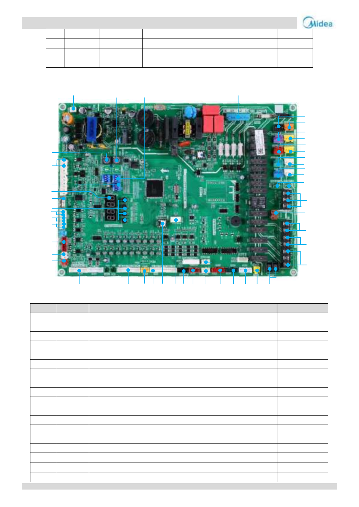
Aqua thermal
Midea Aqua thermal Service Manual
37
S2
/
Reserve
DC3.3V
38
S3
S3-1
1 (Default)
DC3.3V
39
S4
Ability dial
MC-SU75-RN8L-B:0011;
MC-SU140-RN8L-B:0111
DC3.3V
45 46 47 1
44
43
42
41
40
39
38
37
36
35
34
33
2
3
4
5
6
7
8
9
10
11
12
13
14
15
16
17
32 31 30 29 28 27 26 25 24 23 22 21 20 19 18
Label
Code
Port
Voltage
1
CN30
Power supply port/ sequence detection port
400VAC
2
CN12
Quick oil return solenoid valve
230VAC
3
CN80
Injection solenoid valve of compressor system B
230VAC
4
CN47
Injection solenoid valve of compressor system A
230VAC
5
CN5
Water side heat exchanger heater
230VAC
6
CN40
Multi-function solenoid valve
230VAC
7
CN13
Electric of water side heat exchanger heater
230VAC
8
CN41
Liquid bypass solenoid valve
230VAC
9
CN42
Crankcase heater
230VAC
10
CN6
Four-way valve
230VAC
11
CN43
Crankcase heater
230VAC
12
CN4/CN11
Electric heater of water flow switch
230VAC
13
CN87
Three-way valve(For domestic hot water)
230VAC
14
CN86
Spray cooling valve
230VAC
15
CN25
Pump relay
230VAC
16
CN33
COMP-STATE
230VAC
17
CN26
Pipeline auxiliary Heater
230VAC
18
CN24
Alarm signal output
230VAC
For MC-SU90-RN8L-B and MC-SU180-RN8L-B
48
Page 48
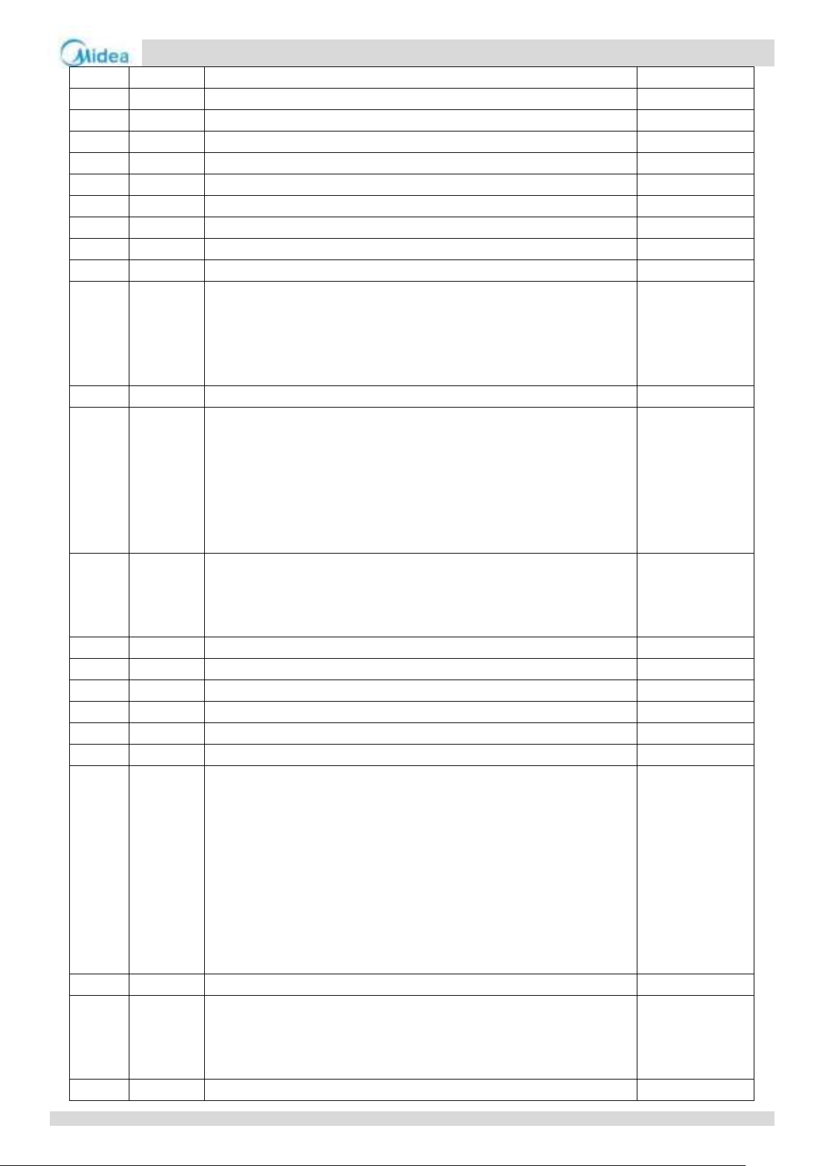
Aqua thermal
Part 4 - Diagnosis and Troubleshooting
19
CN20
Discharge temperature switch
DC12V
20
CN71
System electronic expansion valve(For cooling)
DC12V
21
CN72
Electronic expansion valve(For EVI)
DC12V
22
CN70
System electronic expansion valve1
DC12V
23
CN60
Outdoor units communication or HMI communication port
DC5V
24
CN61
Outdoor units communication or HMI communication port
DC5V
25
CN64
Fan inverter module communication port
DC5V
26
CN65
Compressor inverter module communication port
DC5V
27
CN300
Program burn import (WizPro200RS programming device)
DC5V
28
IC10
EEPROM chip
DC5V
29
CN1
Temperature sensors input port.
T4: Outdoor ambient temperature sensor
T3A/T3B: Pipe temperature sensor of the condenser
T6A: Refrigerant inlet temperature of EVI plate heat exchanger
T6B: Refrigerant inlet temperature of EVI plate heat exchanger
DC5V
30
CN16
System pressure sensor
DC5V
31
CN31
Temperature sensors input port
Th: System suction temperature sensor
Taf2: Water side antifreeze temperature sensor
Two: Unit water outlet temperature sensor
Twi: Unit water inlet temperature sensor
Tw: Total water outlet temperature sensor when several units are connected in
parallel
DC5V
32
CN69
Temperature sensors input port
Tp1 :DC inverter compressor 1 discharge temperature sensor
Tp2:DC inverter compressor 2 discharge temperature sensor
Tz: Coil final outlet temperature sensor
DC5V
33
CN19
Low voltage protection switch
DC5V
34
CN91
Three-phase protector output switch
DC5V
35
CN58
Compressor driver ON/OFF port
DC12V
36
CN8
Remote function of cool/heat port
DC12V
37
CN8
Remote function of on/off port
DC12V
38
CN8
Water flow switch port
DC12V
39
SW3-SW6
SW3: Up button
a) Select different menus when enter menu selection.
b) For spot inspection in conditions.
SW4: Down button
a) Select different menus when enter menu selection.
b) For spot inspection in conditions.
SW5: Menu button
Press to enter menu selection, short press to return to the previous menu.
SW6: OK button
Enter the submenu or confirm the function selected by short pressing.
DC5V
40
USB
Program burn import (USB)
DC5V
41
DSP1/DSP2
Digital tube
1) In case of stand-by, the address of the module is displayed;
2) In case of normal operation, 10. is displayed (10 is followed by dot).
3) In case of fault or protection, fault code or protection code is displayed.
DC5V
42
S5
S5: Dip switch
DC5V
49
Page 49
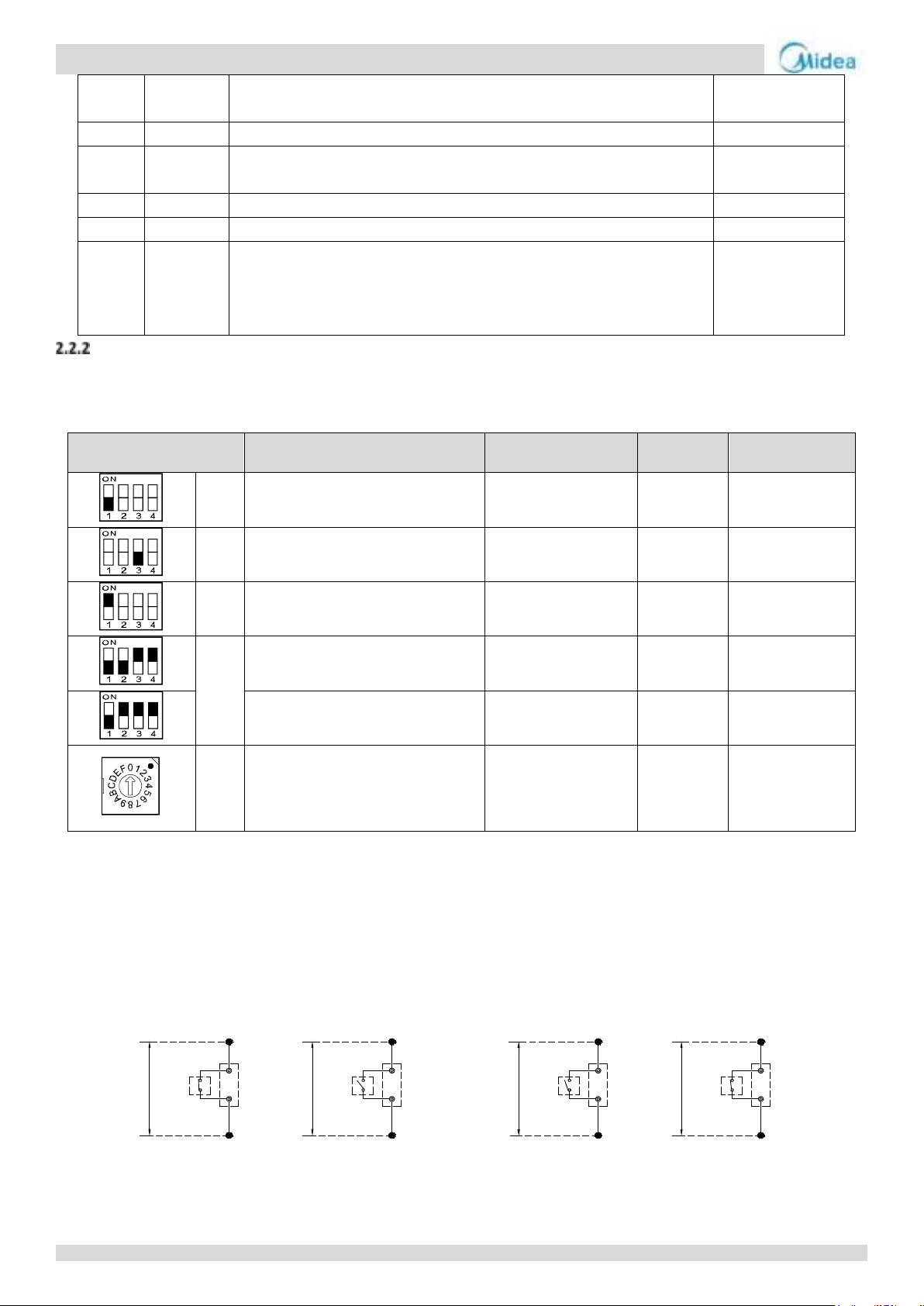
Aqua thermal
Midea Aqua thermal Service Manual
S5-3: Normal control, valid for S5-3 OFF (factory default)
Remote control, valid for S5-3 ON.
43
CN7
Target water temperature switching port
DC12V
44
ENC2
Power DIP switch for capacity selection.
(MC-SU90-RN8L-B defaults 2; MC-SU180-RN8L-B defaults 6 )
DC5V
45
CN74
Power supply port of the HMI
DC9V
46
ENC4
NET_ADDRESS DIP switch (0~15)
DC5V
47
S12
S12: Dip switch
S12-1: Valid for S12-1 ON (factory default)
S12-2: Single water pump control, valid for S12-2 OFF (factory default)
Multiple water pumps control, valid for S12-2 ON。
DC5V
Switch
Description
ON
OFF
Default factory
setting
S1-1
Control mode
Remote control
Normal
control
OFF
S1-3
Water pump
Multiple water pumps
control
Single water
pump
control
OFF
S3-1
-
- - ON
S4
DIP switch for capacity selection
-
-
MC-SU75-RN8L-B:
0011
DIP switch for capacity selection
MC-SU140-RN8L-B:
0111
ENC1
0-F valid for unit address setting
on the DIP switches
0 indicates the master unit and 1-F
the auxiliary units
(parallel connection)
- - 0
0# electric
control box
“HEAT/COOL” port
COOL
Power (DC 12V)
Main control board is provided
0# electric
control box
“HEAT/COOL” port
HEAT
Power (DC 12V)
Main control board is provided
0# electric
control box
“TEMP-SWITCH” port
Power (DC 12V)
Main control board is provided
0# electric
control box
“TEMP-SWITCH” port
Power (DC 12V)
Main control board is provided
Main PCB field setting
Multiple pumps control: output pump signal on all units.
Single pump control: only the master unit output pump signal, no pump signal output on the slave units.
For MC-SU75-RN8L-B and MC-SU140-RN8L-B
Note:
1. Wiring of “HEAT/COOL” weak electric port
The remote function of “HEAT/COOL” must be set by DIP switch. The remote function “HEAT/COOL” is effective when S1-1or S5-3 is chosen ON, at the same time,
the wire controller is out of control.
Corresponding parallel connect the “HEAT/COOL” port of the main unit’s electric control box, then, connect the “ON/OFF” signal (provide by user) to the
“HEAT/COOL” port of main unit as follows.
Wiring method: Shorting the terminal block CN138 at slave board inside the electric control box to enable the remote function of “HEAT/COOL”.
2. Wiring of “TEMP-SWITCH” weak electric port
The function of “TEMP-SWITCH” must be set by wired controller for two setting water temperature. For cooling and heating mode.
Wiring method: Shorting the terminal block CN110 at slave board inside the electric control box to choose the target water temperature.
50
Page 50
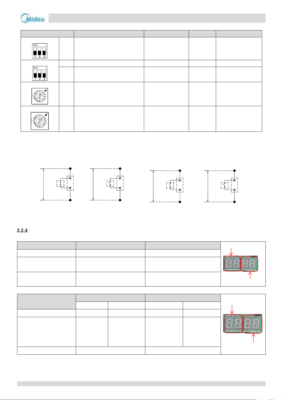
Aqua thermal
Part 4 - Diagnosis and Troubleshooting
0# electric
control box
“ON/OFF” port
ON
Power (DC 12V)
Main control board is provided
0# electric
control box
“ON/OFF” port
OFF
Power (DC 12V)
Main control board is provided
0# electric
control box
“HEAT/COOL” port
COOL
Power (DC 12V)
Main control board is provided
0# electric
control box
“HEAT/COOL” port
HEAT
Power (DC 12V)
Main control board is provided
Switch
Description
ON
OFF
Default factory setting
S5
S5-3
Control mode
Remote control
Normal
control
OFF
S12
S12-1
Default setting
Default setting
-
ON
S12-2
Water pump
Multiple pumps
control
Single pump
control
OFF
ENC2
ENC2
DIP switch for capacity selection
-
-
MC-SU90-RN8L-B :2
MC-SU180-RN8L-B:
6
ENC4
ENC4
Address setting
0: master unit
1,2,3…F: slave units
-
-
MC-SU90-RN8L-B: 0
MC-SU180-RN8L-B: 0
and 1
Outdoor unit state
Parameters displayed on DSP1
Parameters displayed on DSP2
Standby 0 1
Normal operation
Running speed of compressor A in
rotations per second
Running speed of compressor B in
rotations per second
Error or protection
-- or placeholder
Error or protection code
Outdoor unit state
Master parameters displayed
Slave parameters displayed
DSP1
DSP2
DSP1
DSP2
Standby
Address
Online number
Address
No display
Normal operation
Running speed
of compressor
A in rotations
per second
Running speed of
compressor B in
rotations
per second
Running speed of
compressor A in
rotations
per second
Running speed of
compressor B in
rotations
per second
Error or protection
-- or placeholder
Error or protection code
DSP1
DSP2
For MC-SU90-RN8L-B and MC-SU180-RN8L-B
Note:
When using remote control function, first is to dial the S5-3 switch to ON. The operation method is as below:
1. Remote ON/OFF:
Connect a switch between 15 and 24 terminals of block XT2 (Refer to the Part 4, 3.1 Single unit) which can be turned on/off at any time. If the switch is closed,
unit turns on. If the switch is open, unit turns off.
2. Remote cool/heat:
Connect a switch between 14 and 23 terminals of block XT2 (Refer to the Part 4, 3.1 Single unit) which can change operation mode at any time. If the switch is
closed, unit runs in heating mode. If the switch is open, unit runs in cooling mode.
Digital display output
For MC-SU75-RN8L-B, MC-SU90-RN8L-B and MC-SU140-RN8L-B:
For MC-SU180-RN8L-B:
51
Page 51
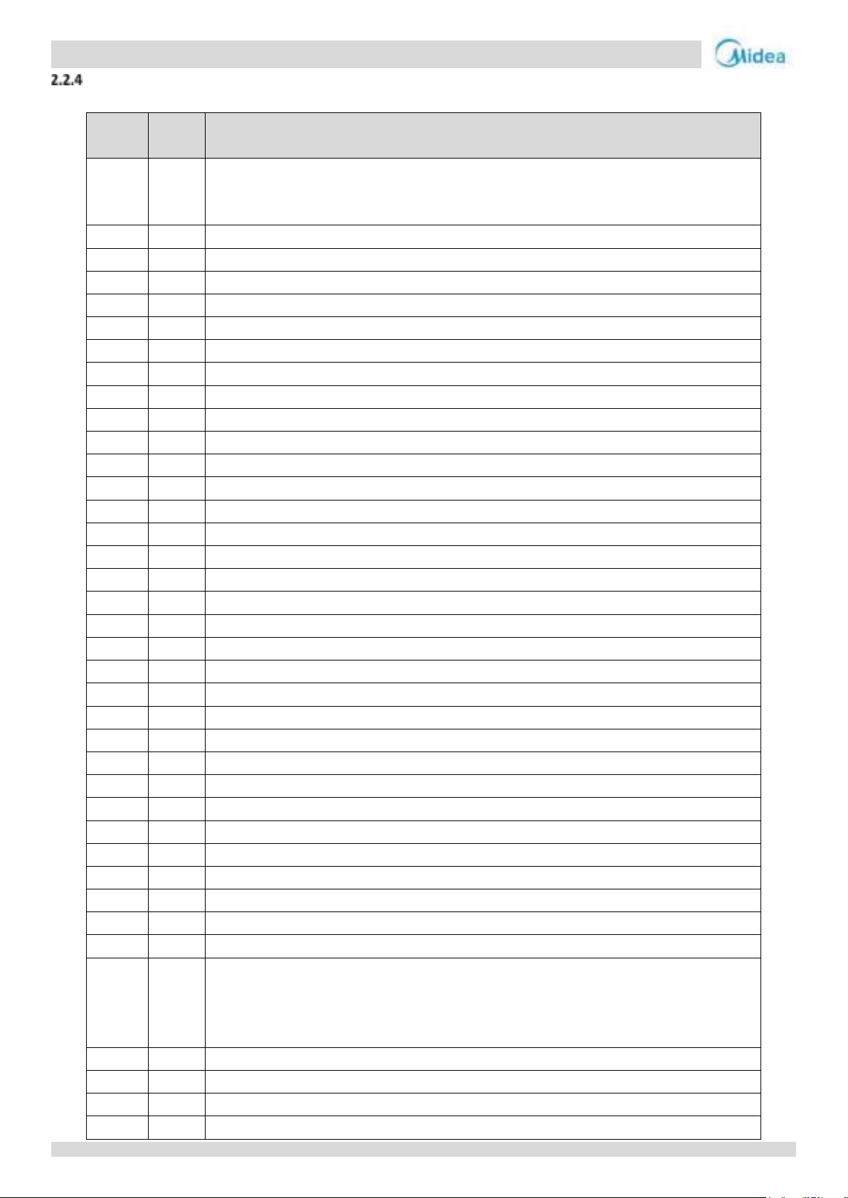
Aqua thermal
Midea Aqua thermal Service Manual
Serial
number
Contents of spot check
0
Standby: host address (left 88) + number of online units (right 88),
Power-on: display frequency
Defrosting: dFdF
1
0.xx
Host address
2
1.xx
Number of external units (e.g. 75/140kW respectively display 75/140.)
3
2.xx
Number of online units (Host valid)
4
3.xx
T4 capacity correction (reserved display "1")
5
4.xx
Operation mode (8 shutdown, 1 cooling, 2 heating, 4 hot water)
6
5.xx
Fan gear (0 – 35)
7
6.xx
Fan gear (reserved display "0")
8
7.xx
T3 (min)
9
8.xx
T4
10
9.xx
Outlet water temperature of T5 water tank
11
10.xx
Taf1
12
11.xx
Taf2
13
12.xx
Tw total outlet water temperature of the unit
14
13.xx
Twi inlet water temperature of the unit
15
14.xx
Two outlet water temperature of the unit
16
15.xx
Tz Temperature of refrigerant liquid pipe at plate changing side
17
16.xx
THeatR heat recovery sensor temperature (reserved display "--")
18
17.xx
Discharge temperature 1
19
18.xx
Discharge temperature 2
20
19.xx
Radiation fin temperature 1
21
20.xx
Radiation fin temperature 2
22
21.xx
Discharge superheat temperature Tdsh
23
22.xx
Compressor A current
24
23.xx
Compressor B current
25
24.xx
--
26
25.xx
Electronic expansion valve A open degree (percent, maximum 100%)
27
26.xx
Electronic expansion valve B open degree (percent, maximum 100%)
28
27.xx
Electronic expansion valve C open degree (percent, maximum 100%)
29
28.xx
High pressure (heating mode)
30
L.xx
Low pressure (with decimal display-display during cooling or standby)
31
30.xx
Refrigeration suction superheat temperature Tssh
32
31.xx
Th suction temperature
33
32.xx
First nixie tube on the right: silent mode selection (0: night silent mode; 1: silent mode; 2:
super silent mode; 3: no silent mode (default))
The second nixie tube on the right: the value of silent mode time selection (0-3) depends on
the parameters of the wired controller
34
33.xx
Static pressure selection (0 static pressure is reserved by default)
35
34.xx
DC voltage A (reserved)
36
35.xx
DC voltage B (reserved)
37
36.xx
Frequency limiting serial number (reserved) (0: infinite frequency; 1: T4 frequency limiting; 2:
Spot Check Description
The spot check sequence is shown as follows:
52
Page 52
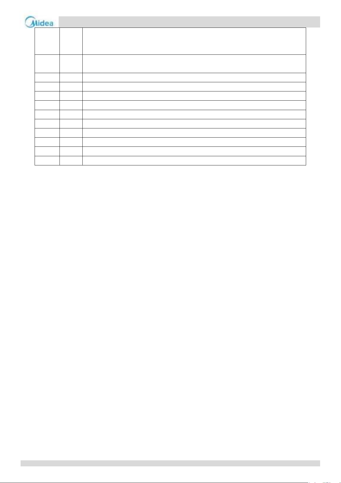
Aqua thermal
Part 4 - Diagnosis and Troubleshooting
Tp exhaust frequency limiting; 3: Tz total cooling output frequency limiting; 4: Tf module
temperature frequency limiting; 5: Two water output frequency limiting 6: Pressure
frequency limiting, 7: Current frequency limiting, 8: Voltage frequency limiting
38
37.xx
Defrosting process status (the first digit: T4 selection scheme; the second digit: interval in the
scheme; the third and fourth digits together represent defrosting timing time)
39
38.xx
Fault of Party E: 1 indicates fault, 0 indicates no fault (reserved 90kw is valid)
40
39.xx
Defrosting scheme
41
40.xx
Initial frequency
42
41.xx
Tc (saturation temperature corresponding to high pressure) spot check value + 30
43
42.xx
Te (saturation temperature corresponding to low pressure) spot check value + 30
44
43.xx
T6a
45
44.xx
T6b
46
45.xx
Version number of main control software
47
46.xx
The last
failure
48
47.xx
----
Note: Need to perform spot check operation on the online controller.
53
Page 53
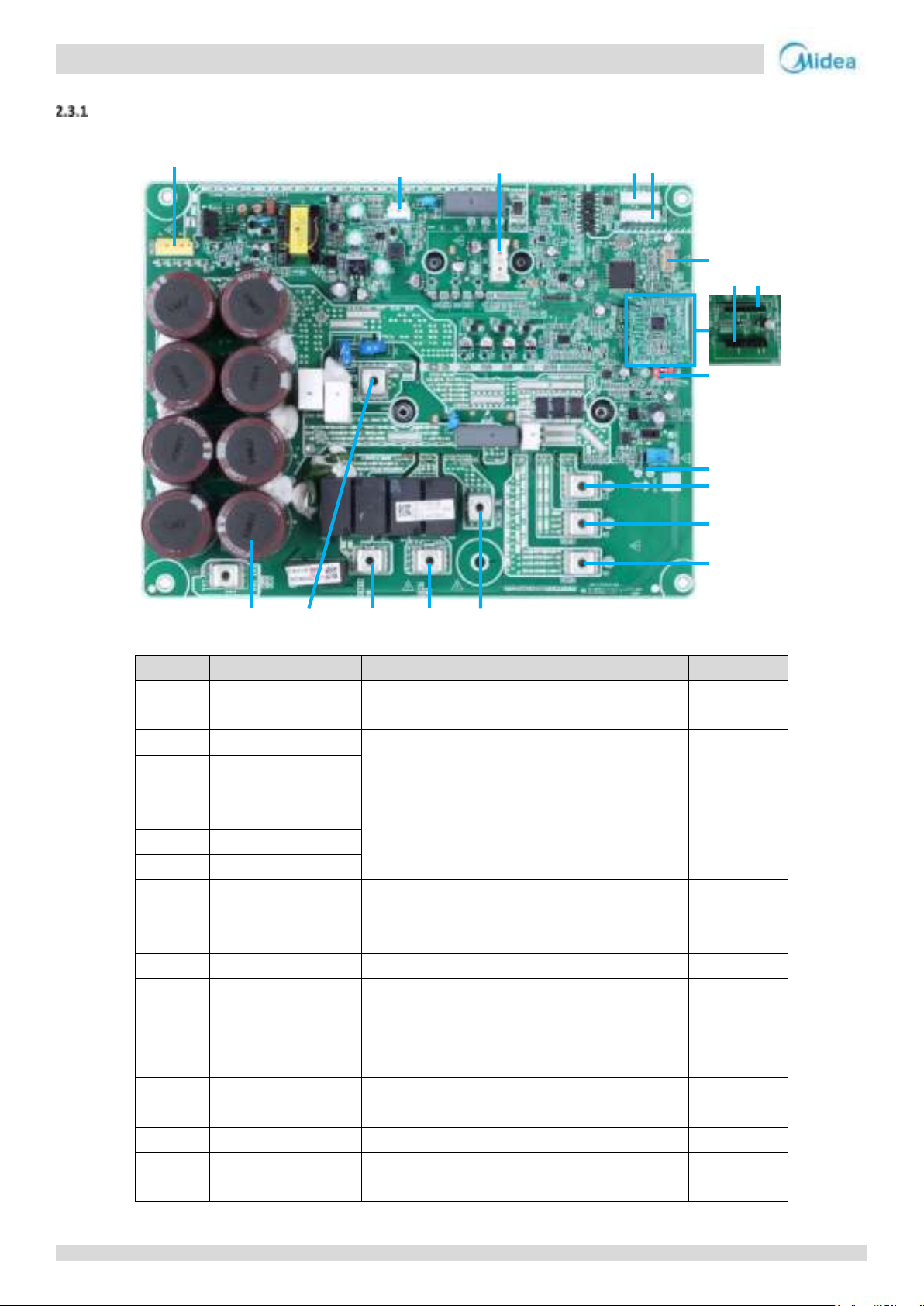
Aqua thermal
Midea Aqua thermal Service Manual
Label
Code
Port
Explanation
Voltage
1
CN1
P-in
Reactor output port
2
CN5
P-out
Reactor input port
3
CN16
L1
Power supply for module board
380-415V
4
CN7
L2 5 CN15
L3 6 CN17
U
Compressor output
7
CN18
V
8
CN19 W 9
CN21
H-SW
High pressure switch
10
S7
module address setting
system A: 00; system B: 01
11
CN27-1
PED board connection port
DC12V/DC5V
12
CN27-2
PED board connection port
DC12V/DC5V
13
CN25
DEBUG
Driver burn port (WizPro200RS programmer)
DC5V
14
CN8
O-Motor
Module Board PTC Relay Control Port/Module Board
Communication Port
DC12V/DC5V
15
CN9
O-Motor
Module Board PTC Relay Control Port/Module Board
Communication Port
DC12V/DC5V
16
CN3
UVW
Fan output port
17
CN26
Fan control power supply output port
DC19V
18
CN39
P N
Fan power supply output port
DC565V
1
2
3
4
16
14
15
5
17
7
6
8
9
10
11 12
13
18
2.3 Compressor Inverter Module Board
Compressor Inverter Module PCB component
For MC-SU75-RN8L-B and MC-SU140-RN8L-B
54
Page 54

Aqua thermal
Part 4 - Diagnosis and Troubleshooting
1
2
3
4
5
18
17
16
15
14
13
12
11
10
6 7 8 9
Label
Code
Port
Voltage
1
CN1
Reactor output port
DC565V
2
CN6
Three-phase power supply in (L1)
400VAC
3
CN5
Reactor input port
DC565V
4
CN7
Three-phase power supply in (L2)
400VAC
5
CN11
Three-phase power supply in (L3)
400VAC
6
CN12
Compressor connection port U
VUV=VUW=VVW
0-380V AC
7
CN13
Compressor connection port V
8
CN14
Compressor connection port W
9
CN20
Power supply for fan module
DC20V
10
S7
Address DIP switch
DC5V
11
CN3
Power supply for compressor board
AC230
AC230
12
CN2
Power supply for compressor board
13
CN23
High pressure switch connection port
DC12V
14
CN22
PED board
DC12V
15
CN9
Compressor board communication port
DC5V
For MC-SU90-RN8L-B and MC-SU180-RN8L-B:
55
Page 55
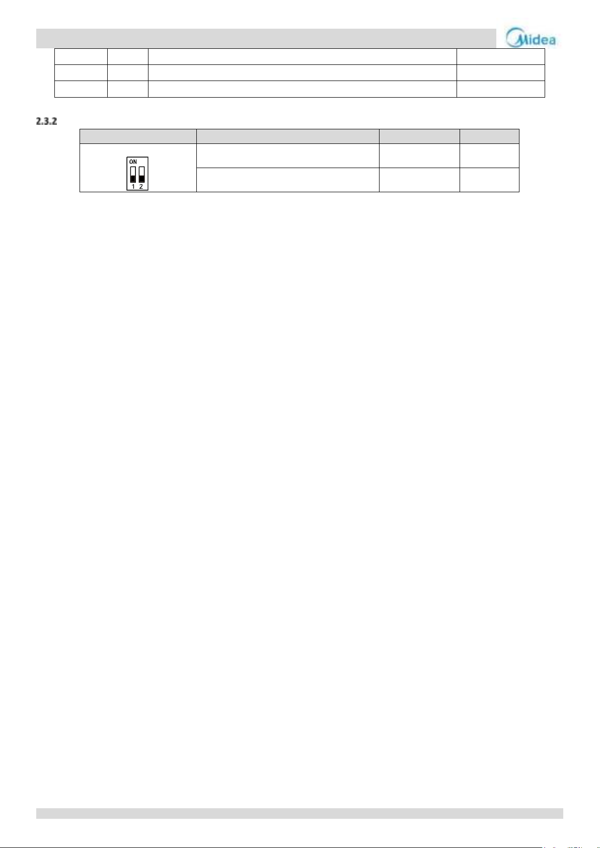
Aqua thermal
Midea Aqua thermal Service Manual
16
CN8
Compressor board communication port
DC5V
17
CN38
Power supply for fan module board
DC565V
18
IC25
EEPROM
DC5V
Switch
Description
S7-1
S7-2
S7
Compressor A inverter module address setting
OFF
OFF
Compressor B inverter module address setting
OFF
ON
Compressor Inverter Module PCB field setting
56
Page 56
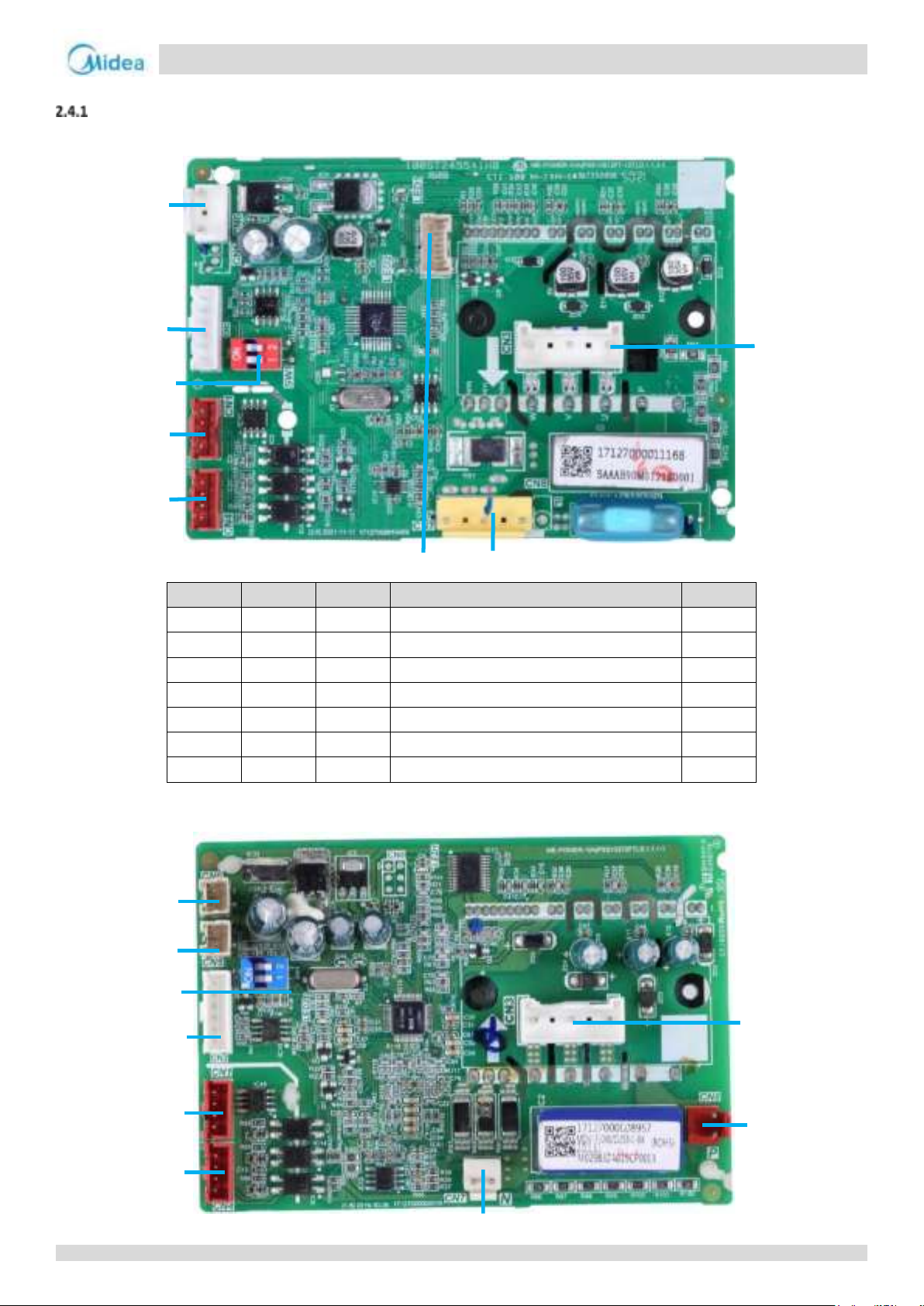
Aqua thermal
Part 4 - Diagnosis and Troubleshooting
Label
Code
Port
Explanation
Voltage
1
CN6
Fan module control power supply input port
DC19V
2
CN12
Reserve
3
SW1
Fan module address setting
4
CN1/CN4
Fan module communication port
DC5V 5 CN9
DEBUG
Program burn port (WizPro200RS programmer)
DC5V
6
CN7
P N
Fan module power supply port
DC565V
7
CN3
UVW
Fan output port
1
2
4
3
4
7
6
5
1
2
3
4
5
6
7
8
9
2.4 Fan Module Board
Fan Module Board component
For MC-SU75-RN8L-B and MC-SU140-RN8L-B
For MC-SU90-RN8L-B and MC-SU180-RN8L-B
57
Page 57
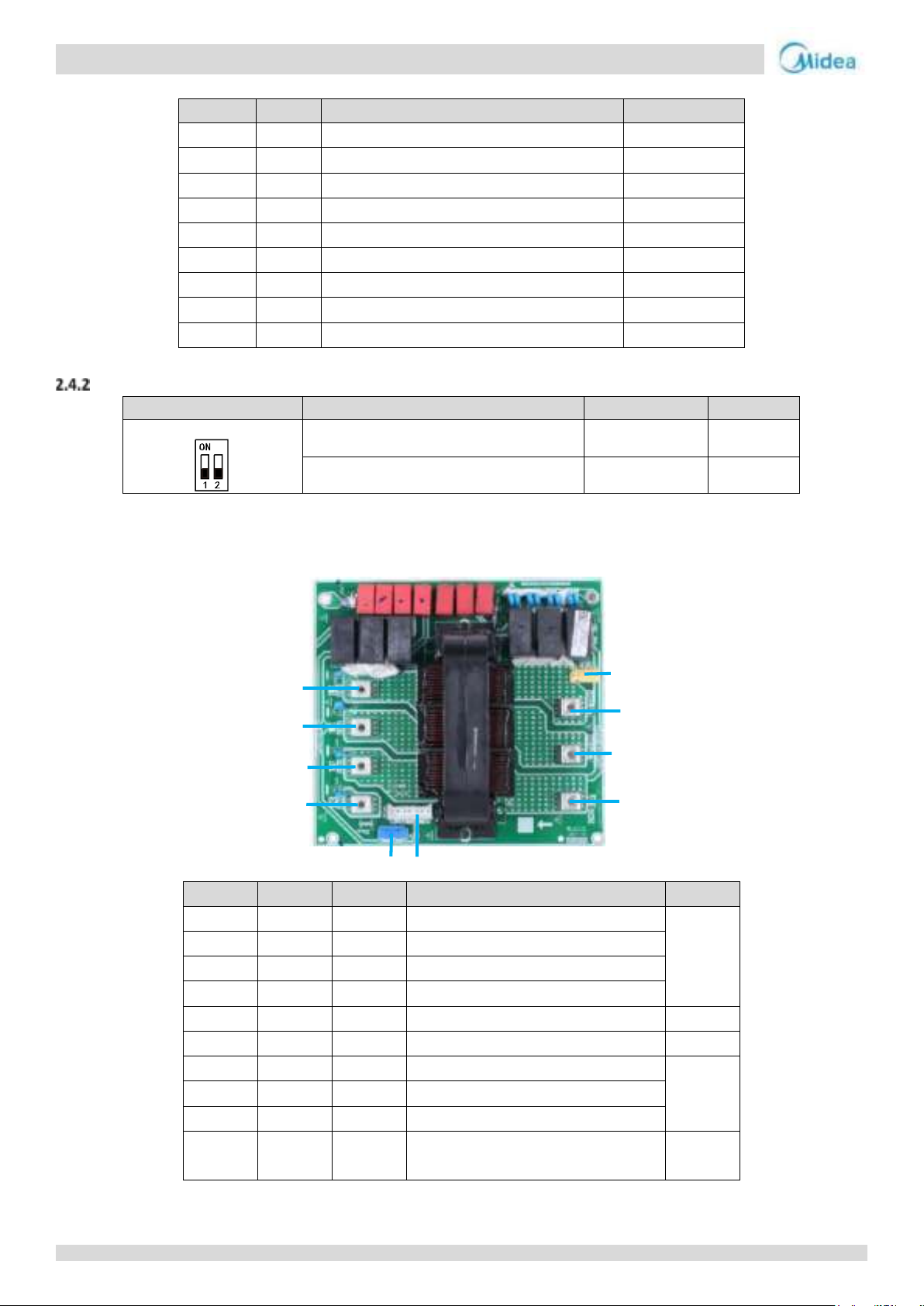
Aqua thermal
Midea Aqua thermal Service Manual
Label
Code
Port
Voltage
1
CN6
Power supply port
DC20V
2
CN5
Power supply port
DC20V
3
SW1
Address DIP switch
DC5V
4
CN2
Program input port
DC5V
5
CN1
Fan module board communication port
DC5V
6
CN4
Fan module board communication port
DC5V
7
CN7
DC bus voltage N
DC565V
8
CN8
DC bus voltage P
DC565V
9
CN3
Fan output port U/V/W
AC 0~380V
Switch
Description
S1-1
S1-2
S1
Fan A inverter module address setting
OFF
OFF
Fan B inverter module address setting
OFF
ON
Label
Code
Port
Explanation
Voltage
1
CN1
L1
Input port L1
380-415V
2
CN2
L2
Input port L2
3
CN3
L3
Input port L3
4
CN4
N
Input port N
5
CN11
Power supply port for main PCB
6
CN12
Port for three phase protector (reserve)
380-415V
7
CN7
L3’
Output port L3
380-415V
8
CN6
L2'
Output port L2
9
CN5
L1'
Output port L1
10
CN16
Three phase water pump power supply
port (reserve)
380-415V
1
2
3
4
5
6
7
8
9
10
Fan Module PCB field setting
2.5 AC Filter Board
For MC-SU75-RN8L-B and MC-SU140-RN8L-B
58
Page 58
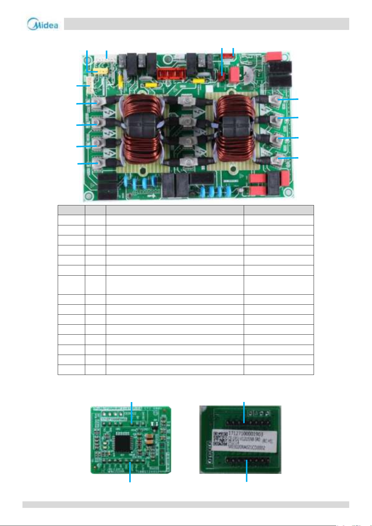
Aqua thermal
Part 4 - Diagnosis and Troubleshooting
Label
Code
Port
Voltage
1
CN4
Input port N
400VAC
2
CN3
Input port L3
400VAC
3
CN2
Input port L2
400VAC
4
CN1
Input port L1
400VAC
5
CN30
Relay driver signal for compressor from main PCB
DC12V
6
CN36
Power supply for compressor inverter module
230VAC
7
CN13
Power supply port for main PCB/Three phase sequence
detection port
230VAC
8
CN34
Power supply for three phase water pump
400VAC
9
CN32
Port for three phase protector
400VAC
10
CN9
Output port L1’
400VAC
11
CN10
Output port L2’
400VAC
12
CN11
Output port L3’
400VAC
13
CN13
Output port N
400VAC
14
CN51
Ground screw hole
/
15
CN50
Ground screw hole
/
4
3
2
1
5
6
7
8
9
10
11
12
13
2
1
2
1
For MC-SU90-RN8L-B and MC-SU180-RN8L-B
2.6 PED Board
59
Page 59
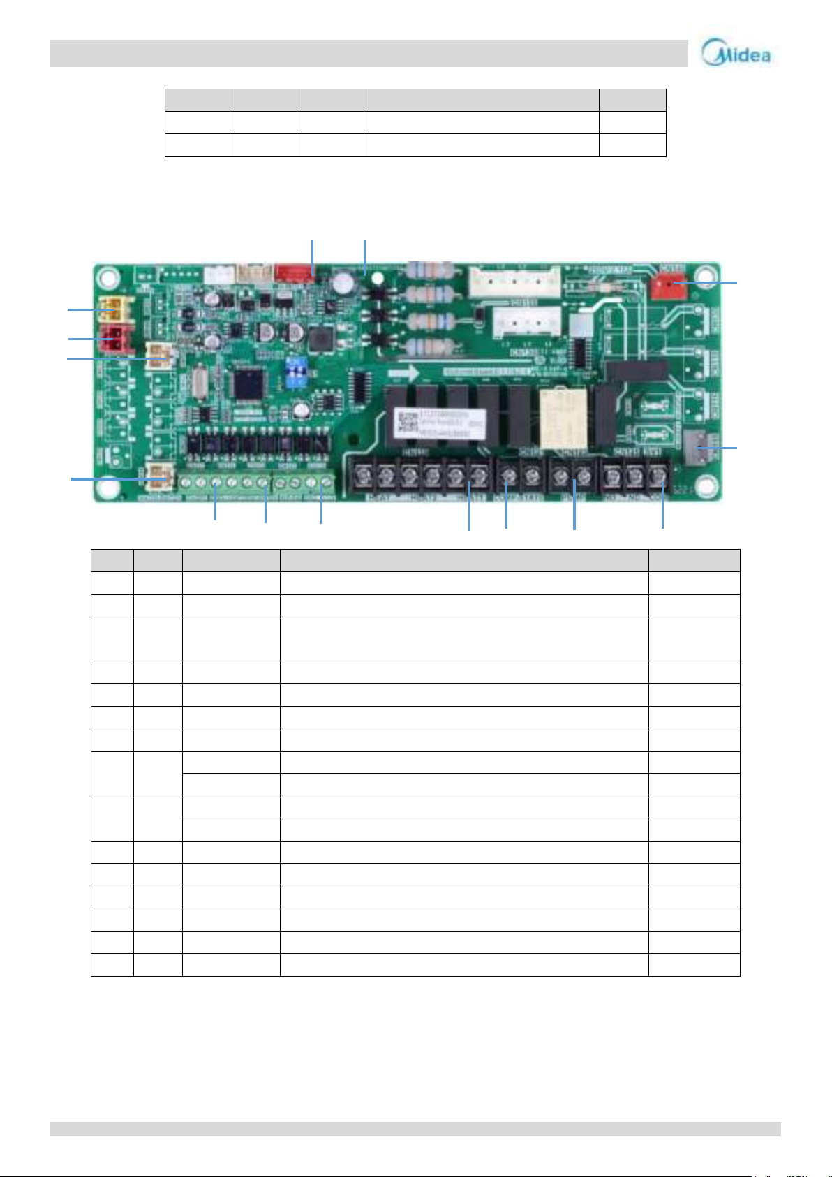
Aqua thermal
Midea Aqua thermal Service Manual
Label
Code
Port
Explanation
Voltage
1
CN26
/
For connecting compressor module board
/ 2 CN27
/
For connecting compressor module board
/
Label
Code
Port
Explanation
Voltage
1
CN140
POWER
Slave PCB board strong power supply
220-240V
2
CN115
W-HEAT
Water pipe electric heating belt
220-240V
3
CN125
3-way valve
Three-way valve for making hot water (used for customized hot
water models)
220-240V
4
CN123
PUMP
Port for water pump contactor control (for market installation)
220-240V
5
CN121
COMP-STATE
Compressor Status Indication
/
6
CN119
HEAT1
Pipe auxiliary motor heating belt
/
7
CN108
PUMP-V
Frequency conversion pump 0-10V control signal
DC 0-10V
8
CN110
W.P-SW
Water pressure difference switch
DC12V
TEMP-SW
Target water temperature switch
DC12V
9
CN138
COOl/HEAT
Remote mode control
DC12V
ON/OFF
Remote switch control
DC12V
10
CN114
WATER-SWITCH
Water flow switch
DC12V
11
CN105
Taf1
Water tank anti-freeze sensor
DC3.3V
12
CN101
TW
Total water sensor
DC3.3V
13
CN103
T5
Water tank sensor
DC3.3V
14
CN300
DEBUG
Main control program burn port (WizPro200RS programmer)
DC3.3V
15
CN109
MS
Communication port of slave PCB board and main PCB board
DC12V/DC3.3V
1
3
4
5
6
7
89
10
12
13
14
15
2.7 Slave PCB Board
For MC-SU75-RN8L-B and MC-SU140-RN8L-B only:
60
Page 60
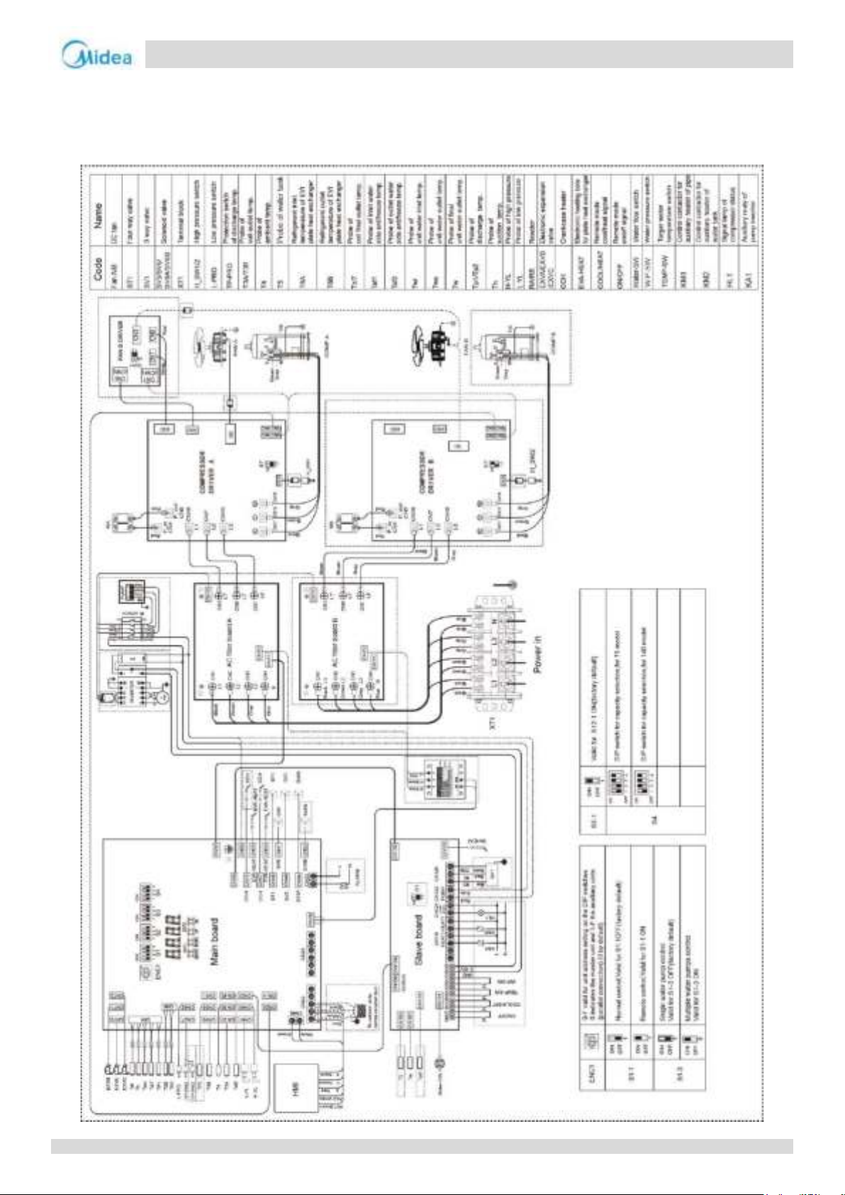
Aqua thermal
Part 4 - Diagnosis and Troubleshooting
3 Wiring diagram
3.1 Single unit
For MC-SU75-RN8L-B and MC-SU140-RN8L-B
61
Page 61
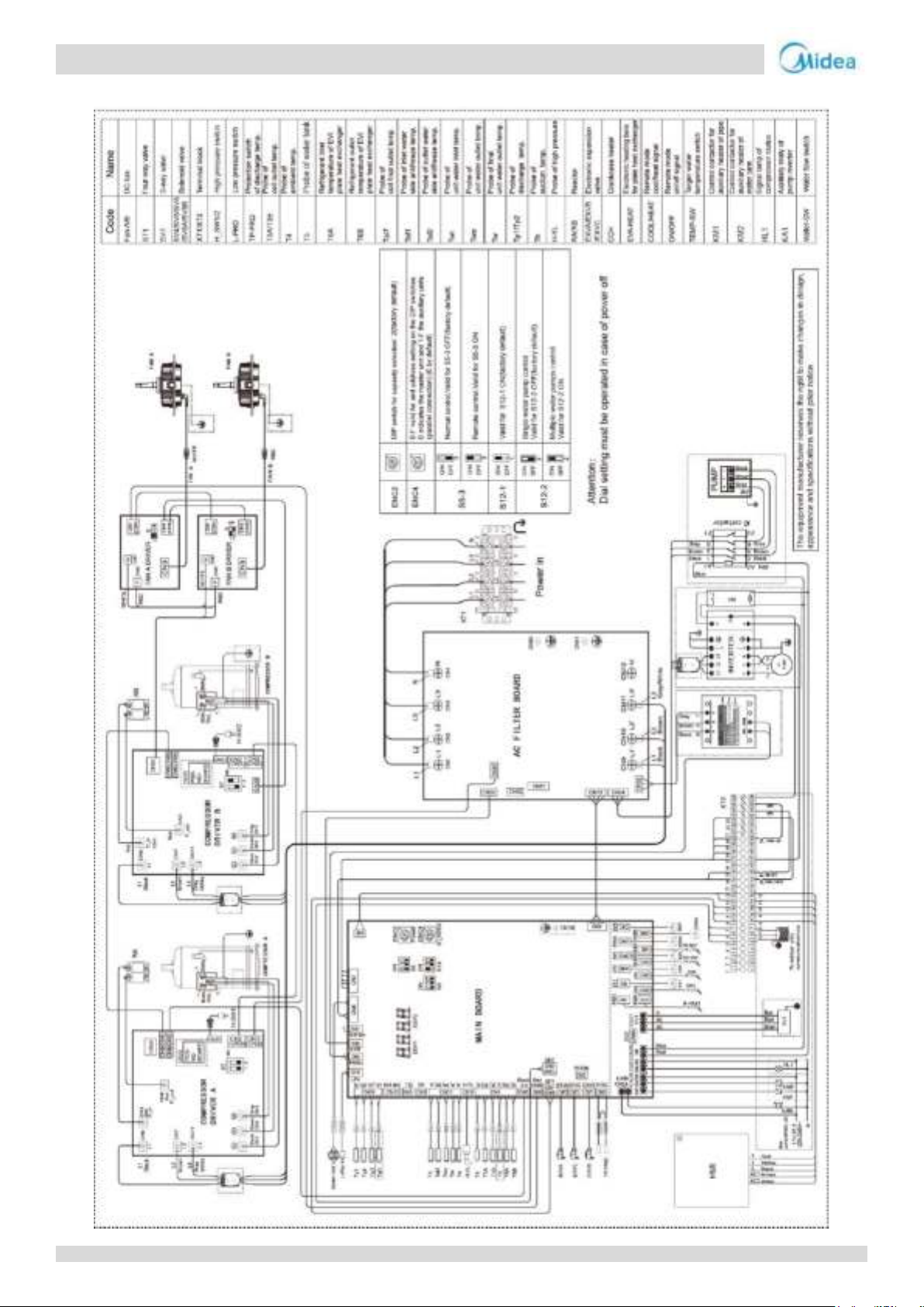
Aqua thermal
Midea Aqua thermal Service Manual
For MC-SU90-RN8L-B:
62
Page 62
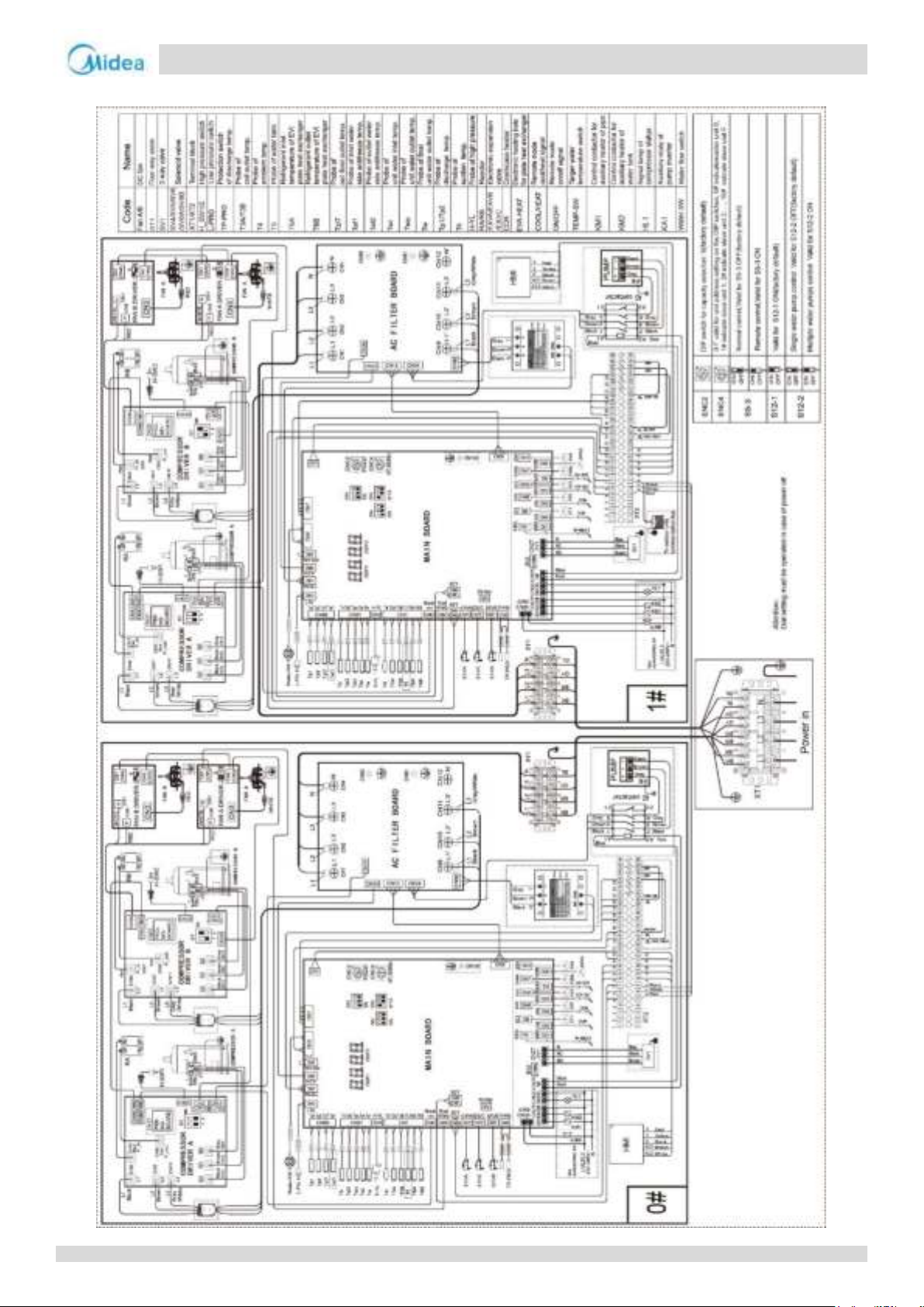
Aqua thermal
Part 4 - Diagnosis and Troubleshooting
For MC-SU180-RN8L-B:
63
Page 63
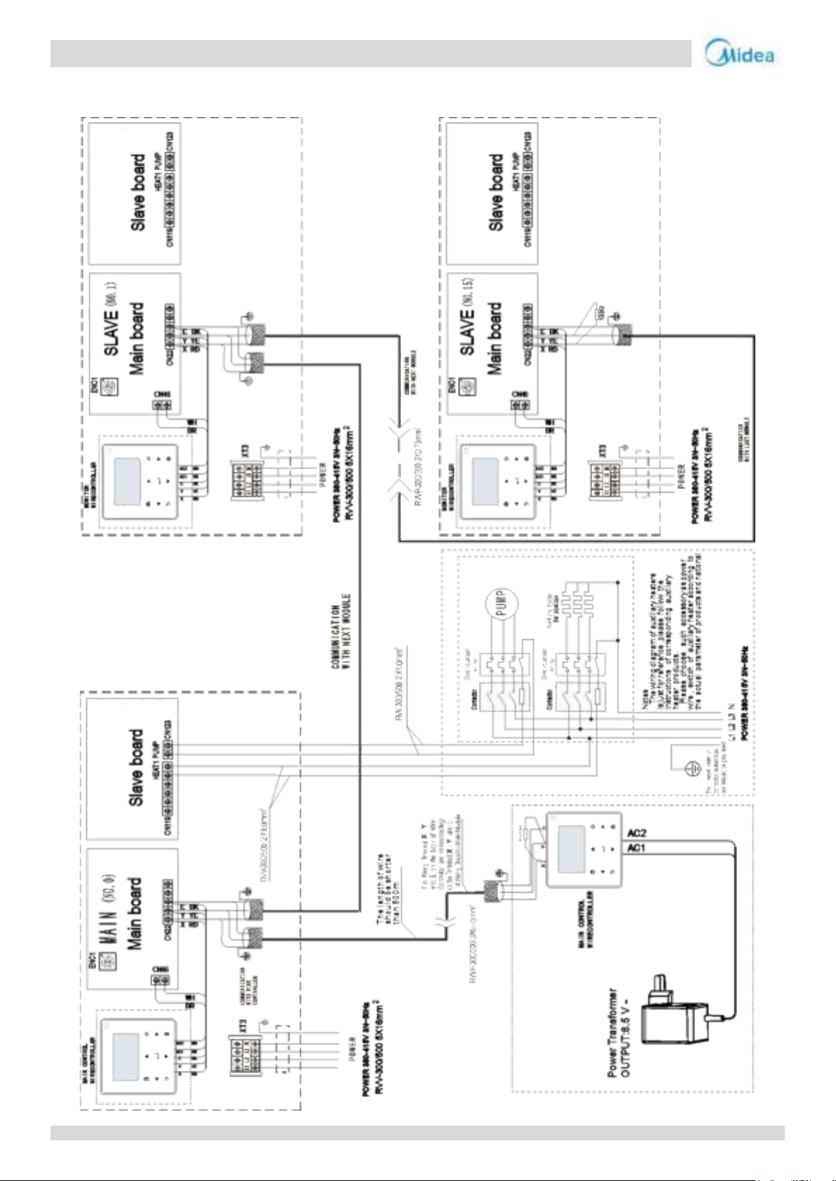
Aqua thermal
Midea Aqua thermal Service Manual
3.2 Multiple units
For MC-SU75-RN8L-B:
64
Page 64
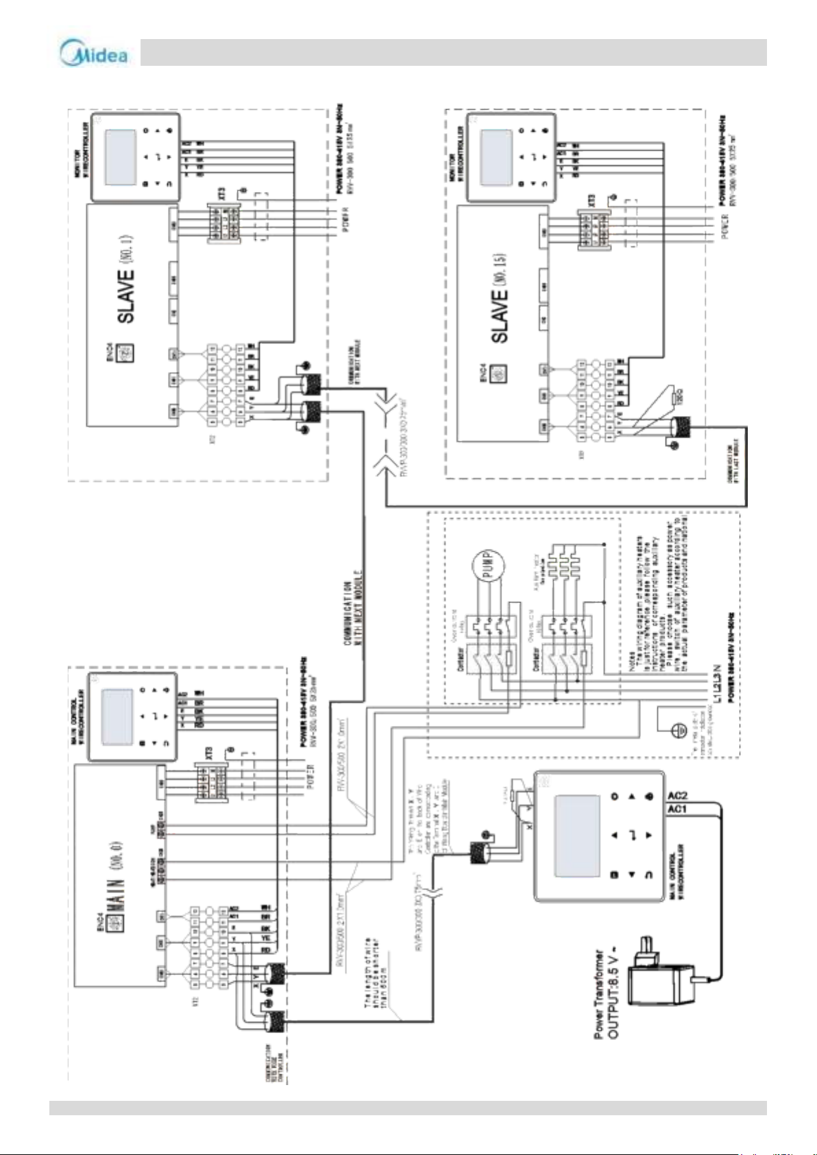
Aqua thermal
Part 4 - Diagnosis and Troubleshooting
For MC-SU90-RN8L-B:
65
Page 65
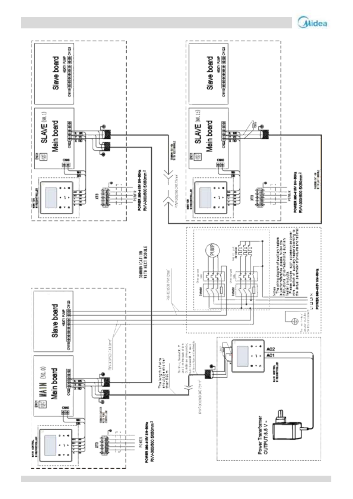
Aqua thermal
Midea Aqua thermal Service Manual
For MC-SU140-RN8L-B:
66
Page 66
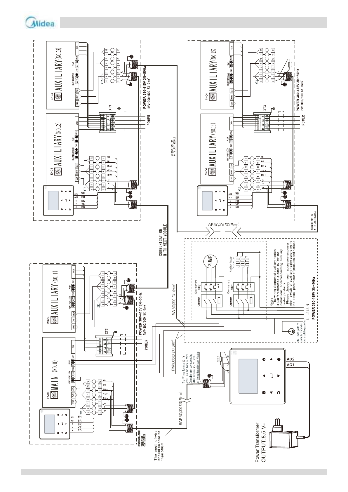
Aqua thermal
Part 4 - Diagnosis and Troubleshooting
7
MONITOR
WIRECONTROLLER
MONITOR
WIRECONTROLLER
7
7
MAIN CONTROL
WIRECONTROLLER
MAIN CONTROL
WIRECONTROLLER
For MC-SU180-RN8L-B:
67
Page 67
Aqua thermal
Midea Aqua thermal Service Manual
Code
Content
Remarks
E0
Main control EPROM error
Displayed on main PCB and user interface
E1
Phase sequence failure of main control board check
Displayed on main PCB and user interface
E2
Main control and wired control transmission error
Displayed on main PCB and user interface
Communication failure between master and slave
E3
Total water outlet temperature sensor error (valid for the main unit)
Displayed on main PCB and user interface
E4
Unit water outlet temperature sensor error
Displayed on main PCB and user interface
E5
1E5 Condenser tube temperature sensor T3A error
Displayed on main PCB and user interface
2E5 Condenser tube temperature sensor T3B error
E6
Water tank temperature sensor T5 error
Displayed on main PCB and user interface
E7
Ambient temperature sensor error
Displayed on main PCB and user interface
E8
Power supply phase sequence protector output error
Displayed on main PCB and user interface
E9
Water flow detection error
Displayed on main PCB and user interface
Eb
1Eb: Taf1 the pipe of hot water side antifreeze protection sensor error
Displayed on main PCB and user interface
2Eb: Taf2 cooling evaporator low-temperature antifreeze protection sensor error
Displayed on main PCB and user interface
EC
Slave unit module reduction
Displayed on main PCB and user interface
Ed
System discharge temperature sensor error
Displayed on main PCB and user interface
EE
1EE EVI plate heat exchanger refrigerant temperature T6A sensor error
Displayed on main PCB and user interface
2EE EVI plate heat exchanger refrigerant temperature T6B sensor error
Displayed on main PCB and user interface
EF
Unit water return temperature sensor error
Displayed on main PCB and user interface
EH
System self-check error alarm (for MC-SU90-RN8L-B and MC-SU180-RN8L-B)
Displayed on main PCB and user interface
EP
Discharge sensor error alarm
Displayed on main PCB and user interface
EU
Tz sensor error
Displayed on main PCB and user interface
P0
P0 System high-pressure protection or discharge temperature protection
Displayed on main PCB and user interface
1P0 Compressor module 1 high pressure protection
Displayed on main PCB and user interface
2P0 Compressor module 2 high pressure protection
Displayed on main PCB and user interface
P1
System low pressure protection
Displayed on main PCB and user interface
P2
Tz total cold outlet temperature too high (for MC-SU90-RN8L-B and
MC-SU180-RN8L-B)
Displayed on main PCB and user interface
P3
T4 ambient temperature too high in cooling mode
Displayed on main PCB and user interface
P4
1P4 System A current protection
Displayed on main PCB and user interface
2P4 System A DC bus current protection
Displayed on main PCB and user interface
P5
1P5 System B current protection
Displayed on main PCB and user interface
2P5 System B DC bus current protection
Displayed on main PCB and user interface
P6
Inverter module failure (for MC-SU90-RN8L-B and MC-SU180-RN8L-B)
Displayed on main PCB and user interface
P7
High temperature protection of system condenser
Displayed on main PCB and user interface
P9
Water inlet and outlet temperature difference protection
Displayed on main PCB and user interface
PA
Abnormal water inlet and outlet temperature difference protection
Displayed on main PCB and user interface
Pb
Winter antifreeze protection
Displayed on main PCB and user interface
PC
Cooling evaporator pressure too low
Displayed on main PCB and user interface
PE
Cooling evaporator low temperature antifreeze protection
Displayed on main PCB and user interface
PH
Heating T4 too high temperature protection
Displayed on main PCB and user interface
PL
Tfin module too high temperature protection
Displayed on main PCB and user interface
4 Error Code Table
68
Page 68
Aqua thermal
Part 4 - Diagnosis and Troubleshooting
Code
Content
Remarks
PU
1PU DC fan A module protection
Displayed on main PCB and user interface
2PU DC fan B module protection
Displayed on main PCB and user interface
H9
1H9 Compressor A inverter module is not matched
Displayed on main PCB and user interface
2H9 Compressor A inverter module is not matched
Displayed on main PCB and user interface
HC
High pressure sensor error
Displayed on main PCB and user interface
HE
1HE No inset A valve error
Displayed on main PCB and user interface
2HE No inset B valve error
Displayed on main PCB and user interface
3HE No inset C valve error
Displayed on main PCB and user interface
F0
1FO IPM module A transmission error
Displayed on main PCB and user interface
2FO IPM module B transmission error
Displayed on main PCB and user interface
F2
Superheat insufficient
Displayed on main PCB and user interface
F4
1F4 module A L0 or L1 protection occurs for 3 times in 60 minutes
Displayed on main PCB and user interface
2F4 module B L0 or L1 protection occurs for 3 times in 60 minutes
Displayed on main PCB and user interface
F6
1F6 A system buss voltage error (PTC)
Displayed on main PCB and user interface
2F6 B system buss voltage error (PTC)
Displayed on main PCB and user interface
Fb
Pressure sensor error
Displayed on main PCB and user interface
Fd
Suction temperature sensor error
Displayed on main PCB and user interface
FF
1FF DC fan A error
Displayed on main PCB and user interface
2FF DC fan B error
Displayed on main PCB and user interface
FP
DIP switch inconsistency of multiple water pumps
Displayed on main PCB and user interface
C7
If PL occurs 3 times, the system reports the C7 failure
Displayed on main PCB and user interface
L0
Compressor inverter module protection (x=1or2) (for MC-SU90-RN8L-B and
MC-SU180-RN8L-B)
Displayed on main PCB
L1
Low-voltage protection (x=1or2) (for MC-SU90-RN8L-B and MC-SU180-RN8L-B)
Displayed on main PCB
L2
High-voltage protection (x=1or2) (for MC-SU90-RN8L-B and MC-SU180-RN8L-B)
Displayed on main PCB
L4
MCE error (x=1or2) (for MC-SU90-RN8L-B and MC-SU180-RN8L-B)
Displayed on main PCB
L5
Zero speed protection (x=1or2) (for MC-SU90-RN8L-B and MC-SU180-RN8L-B)
Displayed on main PCB
L7
Phase sequence error (x=1or2) (for MC-SU90-RN8L-B and MC-SU180-RN8L-B)
Displayed on main PCB
L8
Compressor frequency variation greater than 15Hz within one second protection
(for MC-SU90-RN8L-B and MC-SU180-RN8L-B)
Displayed on main PCB
L9
Actual compressor frequency differs from target frequency by more than 15Hz
protection (for MC-SU90-RN8L-B and MC-SU180-RN8L-B)
Displayed on main PCB
dF
Defrosting prompt (for MC-SU90-RN8L-B and MC-SU180-RN8L-B)
Displayed on main PCB and user interface
bH
1bH Module 1 relay blocking or 908 chip self-check failed
Displayed on main PCB and user interface
2bH Module 2 relay blocking or 908 chip self-check failed
Displayed on main PCB and user interface
Continued:
69
Page 69
Aqua thermal
Midea Aqua thermal Service Manual
All electrical work must be carried out by competent and suitably qualified, certified and accredited professionals and
in accordance with all applicable legislation (all national, local and other laws, standards, codes, rules, regulations and
Power-off the outdoor units before connecting or disconnecting any connections or wiring, otherwise electric shock
Warning
5 Troubleshooting
5.1 Warning
other legislation that apply in a given situation).
(which can cause physical injury or death) may occur or damage to components may occur.
70
Page 70
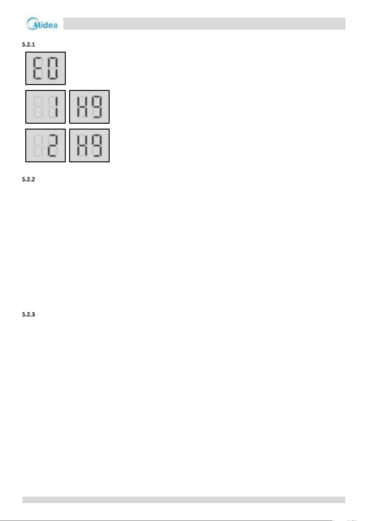
Aqua thermal
Part 4 - Diagnosis and Troubleshooting
5.2 E0/H9 Troubleshooting
Digital display output
Description
For MC-SU75-RN8L-B and MC-SU140-RN8L-B
E0 indicates that the capability dialing code of the main PCB is inconsistent with the actual model.
1H9 indicates that the driving model of IPM inverter module (compressor A) does not match.
2H9 indicates that the driving model of IPM inverter module (compressor B) does not match.
The faulty unit stops running.
Error code is displayed on main PCB and user interface...d user interface.
For MC-SU90-RN8L-B and MC-SU180-RN8L-B
E0 indicates main PCB EEPROM error.
1H9 indicates IPM inverter module (compressor A) EEPROM error.
2H9 indicates IPM inverter module (compressor B) EEPROM error.
The faulty unit stops running.
Error code is displayed on main PCB and user interface...d user interface.
Possible causes
For MC-SU75-RN8L-B and MC-SU140-RN8L-B
The dialing code of main PCB capability is error.
The address dialing code of the IPM inverter module PCB is error.
Main PCB or IPM inverter module damaged.
For MC-SU90-RN8L-B and MC-SU180-RN8L-B
Main PCB or IPM inverter module EEPROM is not connected properly.
Main PCB or IPM inverter module damaged.
EEPROM damaged.
71
Page 71
Aqua thermal
Midea Aqua thermal Service Manual
No
E0/H9
Main PCB or IPM inverter module PCB
dialing code 1 is not correct
Yes
Ensure the dialing code is correct
E0/H9
Main PCB or IPM inverter module EEPROM1
is not connected properly
Yes
Ensure the EEPROM is connected properly
No
EEPROM damaged
Yes
Replace the EEPROM
No
Replace Main PCB or IPM inverter module
PCB
Replace Main PCB or IPM inverter module
PCB
Procedure
For MC-SU75-RN8L-B and MC-SU140-RN8L-B
Notes:
1. Main PCB capability dialing code is designated S4 on the main PCBs (labeled 39 in Part 4, 2.2.1 Main PCB component);
2. Compressor inverter module PCB address dialing code is designated S7 on compressor inverter module PCB.
For MC-SU90-RN8L-B and MC-SU180-RN8L-B
Notes:
1. Main PCB EEPROM is designated IC10 on the main PCBs (labeled 28 in Part 4, 2.2.1 Main PCB component);
2. Compressor inverter module PCB EEPROM is designated IC25 on compressor inverter module PCB (labeled 18 in Part 4, 2.3.1 Compressor Inverter Module PCB
component).
72
Page 72
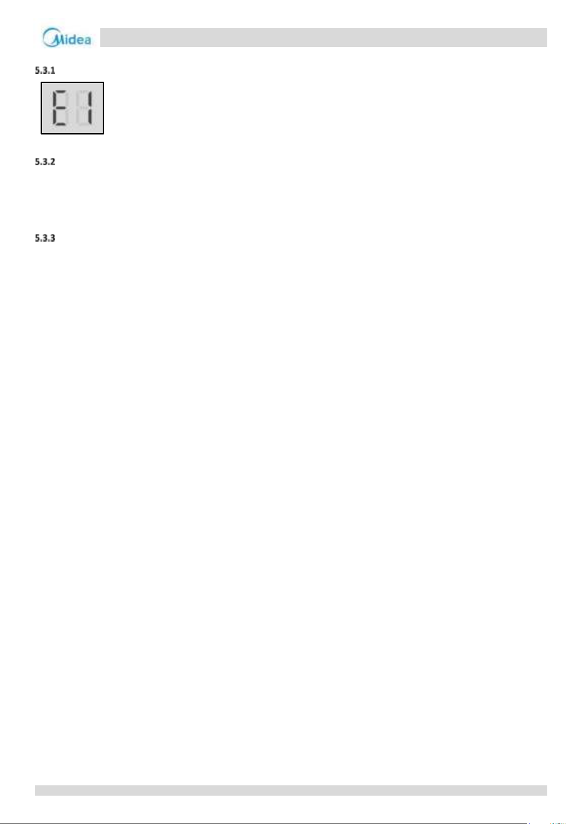
Aqua thermal
Part 4 - Diagnosis and Troubleshooting
5.3 E1 Troubleshooting
Digital display output
Description
Phase sequence error.
The faulty unit stops running.
Error code is displayed on main PCB and user interface.
Possible causes
Power supply phases not connected in correct sequence.
Power supply terminals loose.
Power supply abnormal.
Main PCB damaged.
73
Page 73
Aqua thermal
Midea Aqua thermal Service Manual
E1
The phase sequence of the 3-phase power
supply is incrorrect1
Yes
Exchange any two of the 3 phase wires
No
Some power supply terminals are loose2
Yes
Ensure all supply terminals are securely
fastened
No
The power supply is abnormal
Yes
Check the power supply equipment
No
Replace refrigerant system main PCB
Procedure
Notes:
1. The A, B, C terminals of 3-phase power supply should match compressor phase sequence requirements. If the phase sequence is inverted, the compressor will
operate inversely. If the wiring connection of each outdoor unit is in A, B, C phase sequence, and multiple units are connected, the current difference between C
phase and A, B phases will be very large as the power supply load of each outdoor unit will be on C phase. This can easily lead to tripped circuits and terminal
wiring burnout. Therefore if multiple units are to be used, the phase sequence should be staggered, so that the current is distributed among the three phases
equally.
2. Loose power supply terminals can cause the compressor to operate abnormally and compressor current to be very large.
74
Page 74
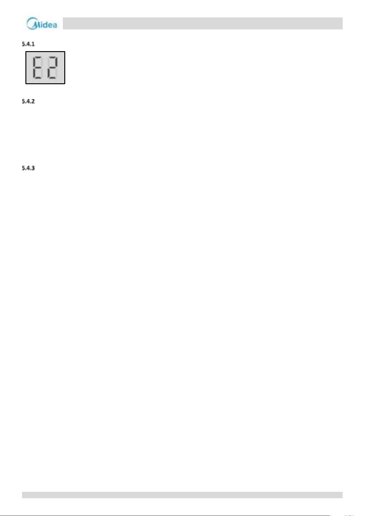
Aqua thermal
Part 4 - Diagnosis and Troubleshooting
5.4 E2 Troubleshooting
Digital display output
Description
Communication error between outdoor unit and user interface.
Communication failure between master and slave units
When this error occurs in the main unit, all units stop running. When this error occurs in the slave unit, the slave unit
stops running.
Error code is displayed on main PCB and user interface.
Possible causes
Communication wires between outdoor unit and user interface not connected properly.
For MC-SU90-RN8L-B, Communication wiring P Q E terminals misconnected. For MC-SU75-RN8L-B, MC-SU140-RN8L-B
MC-SU180-RN8L-B, Communication wiring X Y E terminals misconnected
Wiring connection is loosen
Interference from high voltage wires or other sources of electromagnetic radiation.
Communication wire too long.
Damaged main PCB, user interface or electric control box communication terminals block.
75
Page 75
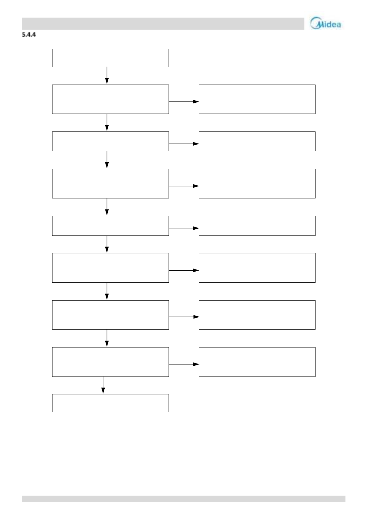
Aqua thermal
Midea Aqua thermal Service Manual
E2
Communication wires P Q E have short
circuited, disconnected or are
misconnected1
Yes
Reconnect the communication wires
No
Communication wires P Q E are not
connected in a daisy chain
Yes
Connect the communication wires in a
daisy chain
No
Wires between outdoor main PCB and
electric control box communication
terminals block are loose
Yes
Ensure the wires are connected properly
No
Interference from high voltage (220V or
higher) wires
Yes
Ensure the communication wires and high
voltage wires are separated
No
Communication wires are close to a source
of electromagnetic radiation such as
transformer or strong fluorescent lamp
Yes
Remove the source of interference, or add
additional shielding to the communication
wires
No
Damaged control box communication
terminals block
Yes
Replacing electric control box
communication terminals block resolves
the error
No
The length of communication wire is over
1200m
Yes
Reduce the wire length to less than
1200mm or strengthen the signal
No
Replace main PCB or user interface
Procedure
For MC-SU90-RN8L-B:
Notes:
1. Measure the resistance among P, Q and E. The normal resistance between P and Q is 120Ω, between P and E is infinite, between Q and E is infinite.
Communication wiring has polarity. Ensure that the P wire is connected to P terminals and the Q wire is connected to Q terminals.
76
Page 76
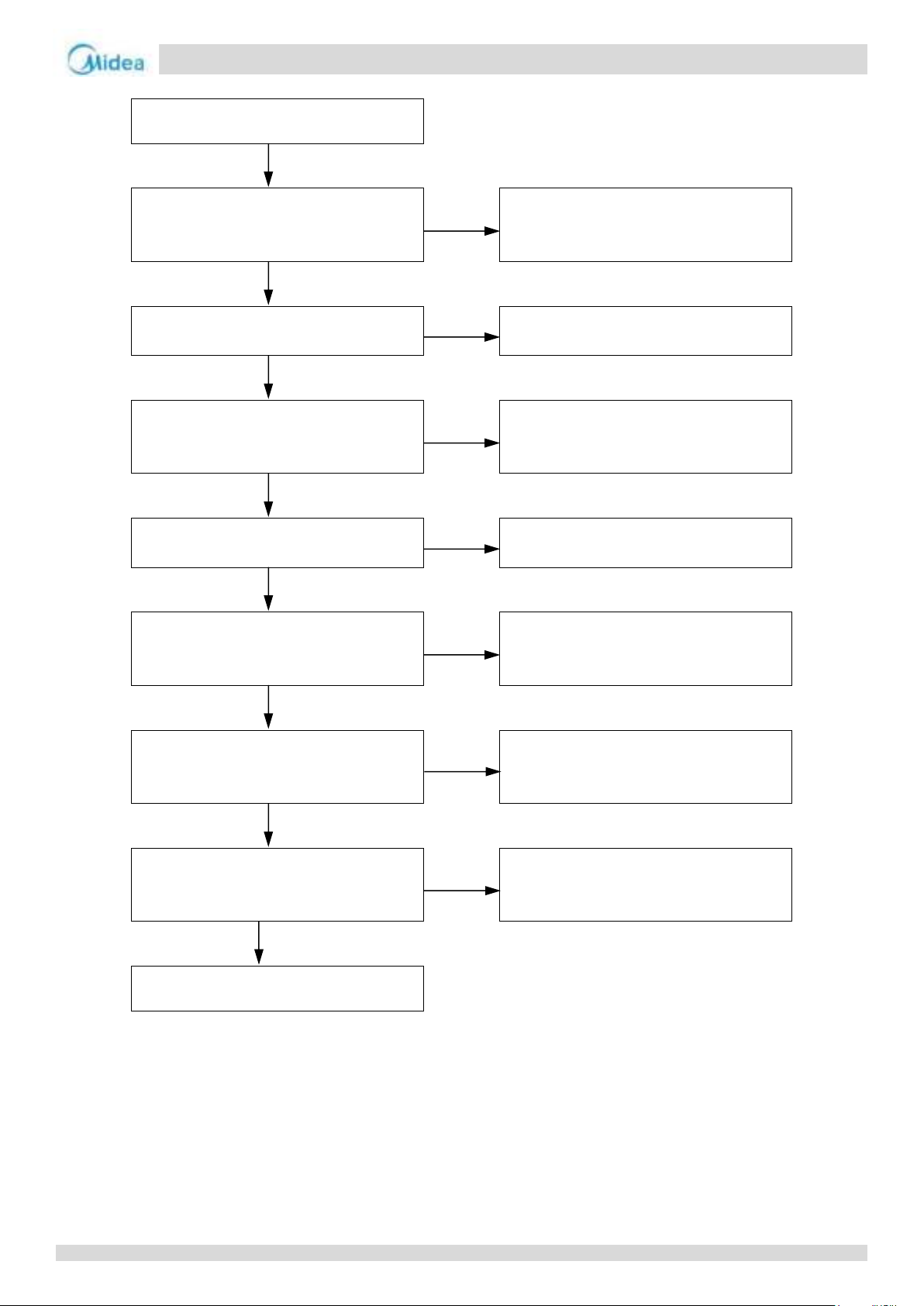
Aqua thermal
Part 4 - Diagnosis and Troubleshooting
E2
Communication wires X Y E have short
circuited, disconnected or are
misconnected1
Yes
Reconnect the communication wires
No
Communication wires X Y E are not
connected in a daisy chain
Yes
Connect the communication wires in a
daisy chain
No
Wires between outdoor main PCB and
electric control box communication
terminals block are loose
Yes
Ensure the wires are connected properly
No
Interference from high voltage (220V or
higher) wires
Yes
Ensure the communication wires and high
voltage wires are separated
No
Communication wires are close to a source
of electromagnetic radiation such as
transformer or strong fluorescent lamp
Yes
Remove the source of interference, or add
additional shielding to the communication
wires
No
Damaged control box communication
terminals block
Yes
Replacing electric control box
communication terminals block resolves
the error
No
The length of communication wire is over
1200m
Yes
Reduce the wire length to less than
1200mm or strengthen the signal
No
Replace main PCB or user interface
For MC-SU75-RN8L-B, MC-SU140-RN8L-B and MC-SU180-RN8L-B:
Notes:
1. Measure the resistance among X, Y and E. The normal resistance between X and Y is 120Ω, between X and E is infinite, between Y and E is infinite.
Communication wiring has polarity. Ensure that the P wire is connected to P terminals and the Q wire is connected to Q terminals.
2. Check whether the communication wires X, Y and E between units have disconnected or are misconnected.
77
Page 77
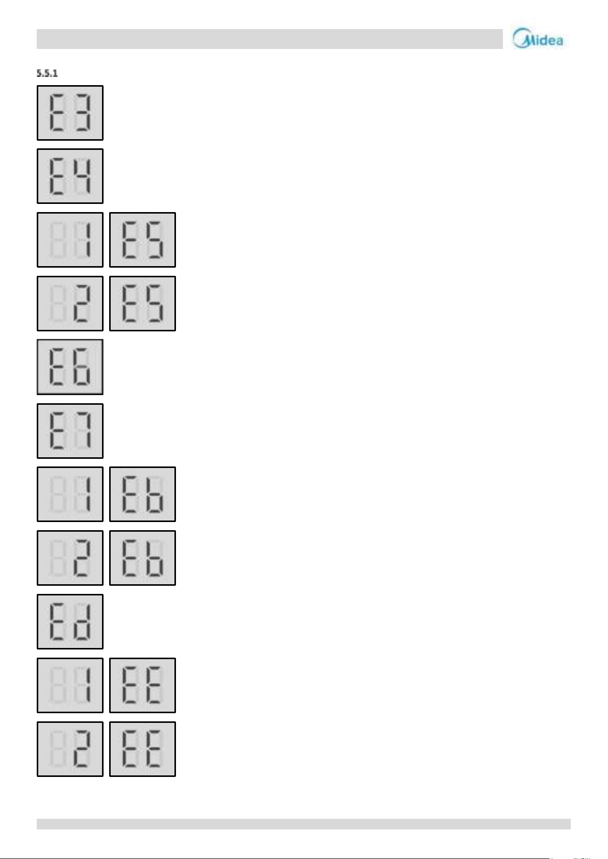
Aqua thermal
Midea Aqua thermal Service Manual
5.5 E3, E4, E5, E7, Eb, Ed, EE, EF, EP, EU, Fb, Fd Troubleshooting
Digital display output
78
Page 78
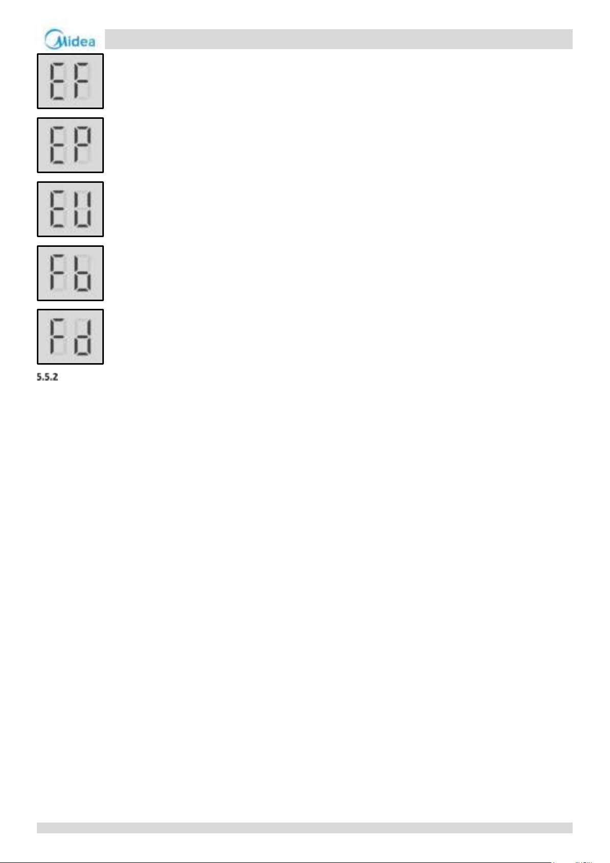
Aqua thermal
Part 4 - Diagnosis and Troubleshooting
Description
For MC-SU75-RN8L-B and MC-SU140-RN8L-B
E3 indicates total water outlet temperature sensor error (valid for the main unit)
E4 unit water outlet temperature sensor error
1E5 indicates condenser tube temperature sensor T3A error
2E5 indicates condenser tube temperature sensor T3B error
E6 Water tank temperature sensor T5 failure
E7 indicates ambient temperature sensor error
1Eb indicates pipe of the tank antifreeze protection sensor Taf1 error
2Eb indicates cooling evaporator low-temperature antifreeze protection sensor Taf2 error
Ed indicates discharge pipe temperature sensors Tp1 and Tp2 error at the same time
1EE indicates EVI plate heat exchanger refrigerant temperature sensor T6A error
2EE indicates EVI plate heat exchanger refrigerant temperature sensor T6B error
EF indicates unit water return temperature sensor error
EP indicates discharge temperature sensor failure error
EU indicates water side heat exchanger refrigerant total outlet temperature sensor Tz error in heating mode.
Fb indicates Low pressure sensor error.
Fd indicates suction temperature sensor Th error.
All stop running.
Error code is displayed on main PCB and user interface.
For MC-SU90-RN8L-B and MC-SU180-RN8L-B
E3 indicates total water outlet temperature sensor error (valid for the main unit)
E4 unit water outlet temperature sensor error
1E5 indicates condenser tube temperature sensor T3A error
2E5 indicates condenser tube temperature sensor T3B error
E7 indicates ambient temperature sensor error
1Eb indicates pipe of the tank antifreeze protection sensor Taf1 error
79
Page 79
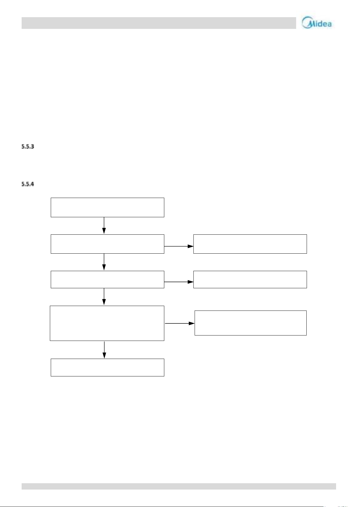
Aqua thermal
Midea Aqua thermal Service Manual
No
Yes
E3 / E4 / E5 / E6 /E7 / Eb / Ed /EE/ EF / EP
/ EU / Fb / Fd
Sensor connection on main PCB or slave
PCB is loose
Yes
Ensure the sensor is connected properly
No
Sensor has short-circuited or failed2
Yes
Replace the sensor
No
Replace main PCB or expansion PCB
If the fault is EP, it is also necessary to
confirm whether the exhaust sensor on
the top of the compressor has fallen
Confirm whether the exhaust sensor on
the top of the compressor has fallen
2Eb indicates cooling evaporator low-temperature antifreeze protection sensor Taf2 error
Ed indicates discharge pipe temperature sensors Tp1 and Tp2A error at the same time
1EE indicates EVI plate heat exchanger refrigerant temperature sensor T6A error
2EE indicates EVI plate heat exchanger refrigerant temperature sensor T6B error
EF indicates unit water return temperature sensor error
EP indicates discharge temperature sensor failure error
EU indicates air side heat exchanger refrigerant total outlet temperature sensor Tz error.
Fb indicates pressure sensor error.
Fd indicates suction temperature sensor Th error.
All stop running.
Error code is displayed on main PCB and user interface.
Possible causes
Sensor not connected properly or has malfunctioned.
Damaged main PCB.
Procedure
For MC-SU75-RN8L-B and MC-SU140-RN8L-B
Notes:
1. Most sensors are connected to ports CN4 (E4), CN37 (1E5), CN16 (2E5), CN30 (E7), CN45 (2Eb), CN4 and CN38 (Ed), CN8 (EE), CN4 (EF), CN4 and CN38 (EP),
CN4 (EU), CN41 (Fb), CN4 (Fd) on the main PCB (labeled 29, 22, 24, 23, 21, 25, 28, 19 in Part 4, 2.2.1 Main PCB component), A few sensors are connected to ports
CN101 (E3), CN103 (E6), CN105 (1Eb) on the slave PCB (labeled 14,15,13 in Part 4, 2.7 Slave PCB component).
2. Measure sensor resistance. If the resistance is too low, the sensor has short-circuited. If the resistance is not consistent with the sensor’s resistance
characteristics table, the sensor has failed. Refer to Part 4, 6.1 “Temperature Sensor Resistance Characteristics”.
80
Page 80
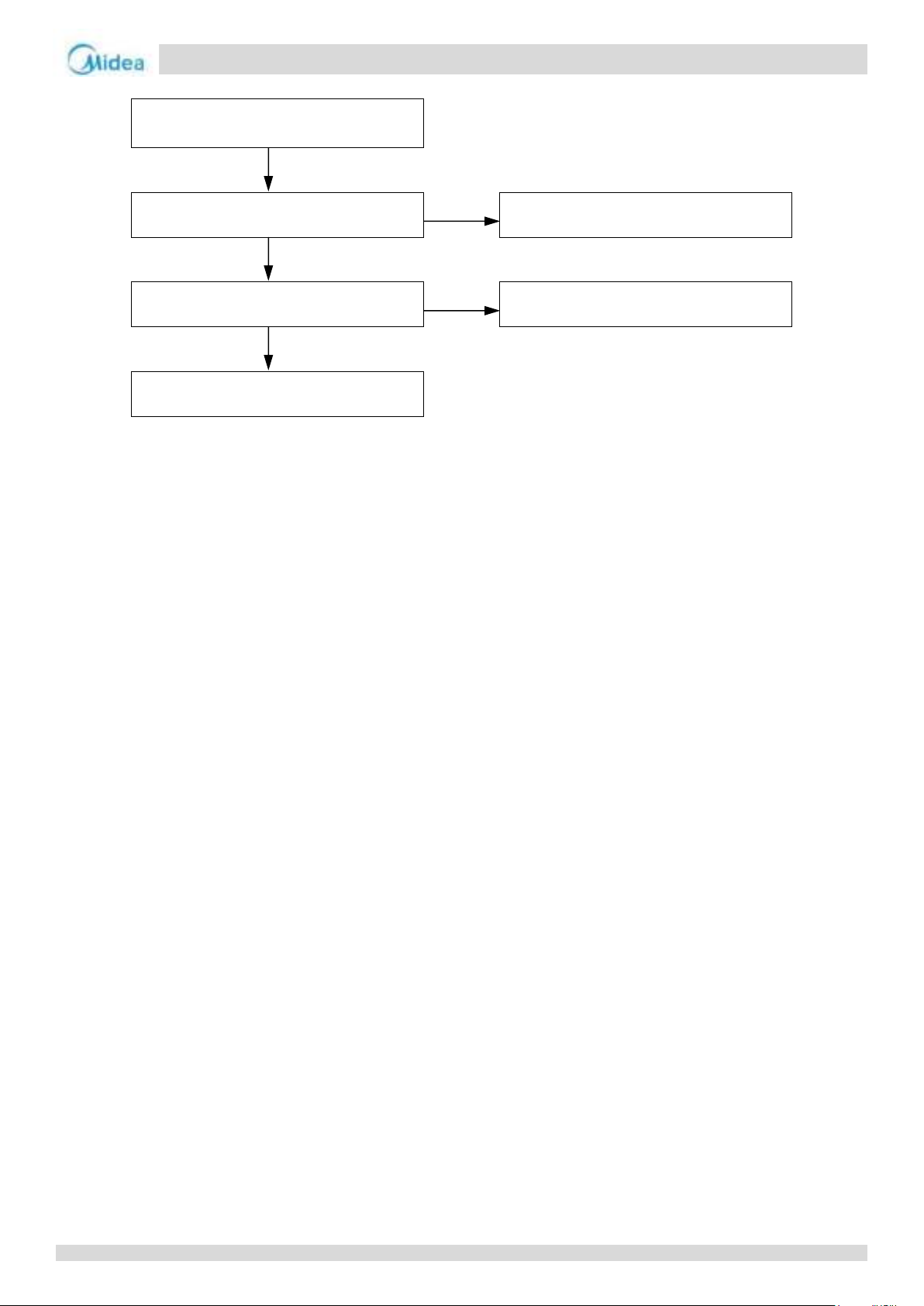
Aqua thermal
Part 4 - Diagnosis and Troubleshooting
E3 / E4 / E5 / E7 / Eb / Ed /EE/ EF / EP / EU
/ Fb / Fd
Sensor connection on main PCB is loose
Yes
Ensure the sensor is connected properly
No
Sensor has short-circuited or failed2
Yes
Replace the sensor
No
Replace main PCB
For MC-SU90-RN8L-B and MC-SU180-RN8L-B
Notes:
1. All the sensors are connected to port CN1, CN16, CN31, CN3, CN10 and CN69 on the main PCB (labeled 29, 30, 31, 32 in Part 4, 2.2.1 Main PCB component).
2. Measure sensor resistance. If the resistance is too low, the sensor has short-circuited. If the resistance is not consistent with the sensor’s resistance
characteristics table, the sensor has failed. Refer to Part 4, 6.1 “Temperature Sensor Resistance Characteristics”.
81
Page 81
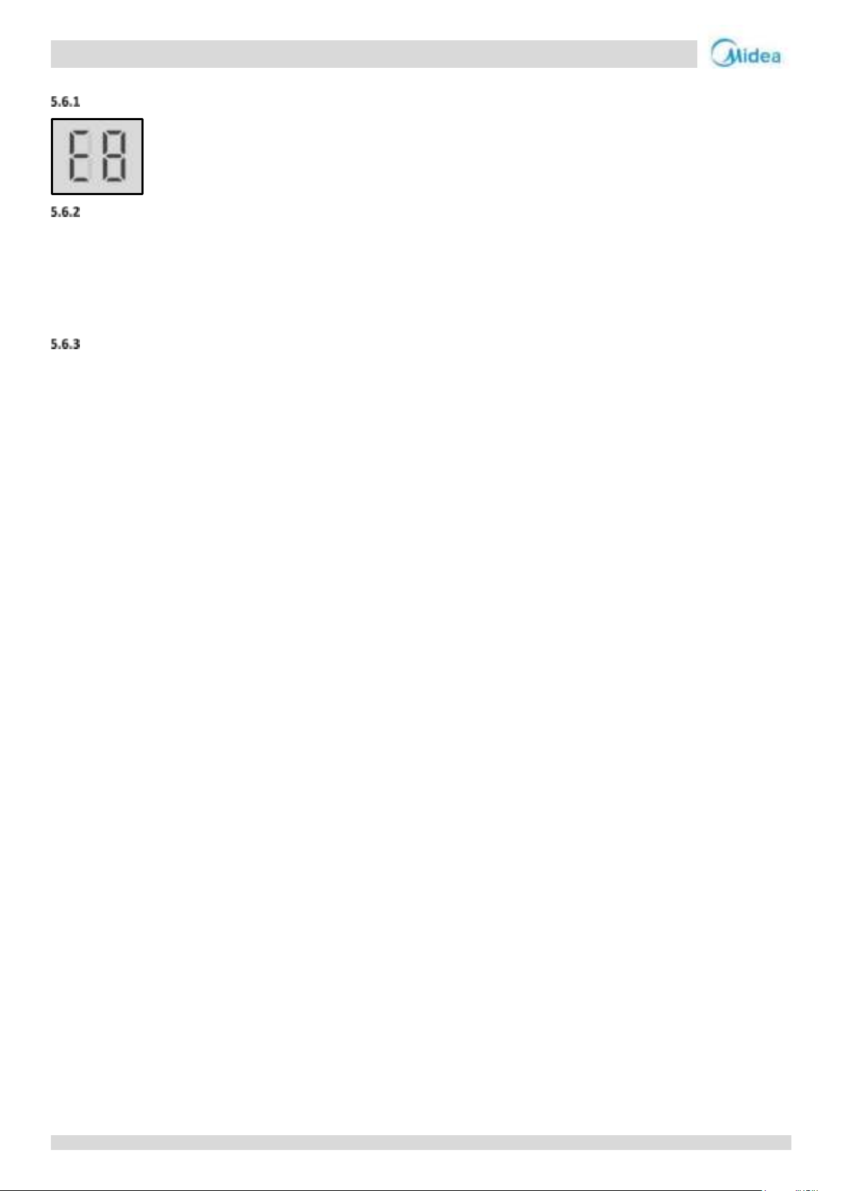
Aqua thermal
Midea Aqua thermal Service Manual
5.6 E8 Troubleshooting
Digital display output
Description
Power supply phase sequence protector output error
When this error occurs in the main unit, all units stop running. When this error occurs in the slave unit, the slave unit stops
running.
Error code is displayed on main PCB and user interface.
Possible causes
Power supply phases not connected in correct sequence or lose.
Power supply terminals or Power phase protector wire connection loose.
Power supply abnormal.
Damaged main PCB.
Damaged power phase protector.
82
Page 82
Aqua thermal
Part 4 - Diagnosis and Troubleshooting
E8
The phase sequence of the 3-phase power
supply is incrorrect1
Yes
Exchange any two of the 3 phase wires
No
Power supply phases lose2
Yes
Ensure all power supply phases is complete
No
Some power supply terminals are loose3
Yes
Ensure all supply terminals are securely
fastened
No
The power supply is abnormal4
Yes
Check the power supply equipment
No
Power phase protector wire connection
loose5
Yes
Check the wire connection of Power phase
protector
No
Replace power phase protector
Yes
Error code disappear
No
Replace Main PCB
Procedure
Notes:
1. The red LED on the power phase protector will on.
2. The red LED on the power phase protector will flash with 1HZ.
3. The A, B, C terminals of 3-phase power supply should match compressor phase sequence requirements. If the phase sequence is inverted, the compressor
will operate inversely. If the wiring connection of each outdoor unit is in A, B, C phase sequence, and multiple units are connected, the current difference
between C phase and A, B phases will be very large as the power supply load of each outdoor unit will be on C phase. This can easily lead to tripped
circuits and terminal wiring burnout. Therefore if multiple units are to be used, the phase sequence should be staggered, so that the current is distributed
among the three phases equally.
4. The red LED on the power phase protector will flash with 3HZ. Loose power supply terminals can cause the compressor to operate abnormally and
compressor current to be very large.
5. For MC-SU75-RN8L-B and MC-SU140-RN8L-B, wire connected to port CN28 on the main PCB. For MC-SU90-RN8L-B and MC-SU180-RN8L-B, wire connected
to port CN91 on the main PCB. (labeled 34 in Part 4, 2.2.1 Main PCB component)
83
Page 83
Aqua thermal
Midea Aqua thermal Service Manual
E9
Water flow switch connection on main PCB
is loose1
Yes
Ensure the switch is connected properly
No
Water flow is insufficient
Yes
Check the water piping and valves. Make
sure the water piping is clean, there is no
air in the water piping and all valves are
open. Make sure the water pump capacity
is enough.
No
Water flow switch is damaged
Yes
Replace the water flow switch
No
Replace main PCB
5.7 E9 Troubleshooting
Digital display output
Description
Water flow failure.
E9 indicates water flow switch error. When E9 error occurs 3 times in 60 minutes, manual system restart is required before
the system can resume operation.
The faulty unit stops running.
Error code is displayed on main PCB and user interface.
Possible causes
The wire circuit is short connected or open.
Water flow rate is too low.
Water flow switch damaged.
Damaged main PCB.
Procedure
Notes:
1. For MC-SU75-RN8L-B and MC-SU140-RN8L-B, Water flow switch connection is port CN114 on the slave PCB (labeled 12 in Part 4, 2.7 Slave PCB
component).
2. For MC-SU90-RN8L-B and MC-SU180-RN8L-B, Water flow switch connection is port CN8 on the main PCB (labeled 38 in Part 4, 2.2.1 Main PCB
component).
84
Page 84
Aqua thermal
Part 4 - Diagnosis and Troubleshooting
EC
Some outdoor units in the system are
powered off1
Yes
Power on all the outdoor units
No
The power supply is abnormal
Yes
Check the power supply equipment
No
Troubleshoot as for an E2 error2
5.8 EC Troubleshooting
Digital display output
Description
EC indicates that the number of slave units detected by master unit has decreased.
The slave unit that has lost contact with the main unit stops running.
Error code is only displayed on the user interface.
Possible causes
Some outdoor units power off.
Power supply abnormal.
Incorrect outdoor unit address setting.
Communication wires between outdoor units not connected properly.
Wiring connection is loosen.
Damaged main PCB or electric control box communication terminals block.
Procedure
Notes:
1. For MC-SU75-RN8L-B and MC-SU140-RN8L-B, check digital display on the main PCB. If digital display is on, the main PCB is powered on, if digital display is
off, the main PCB is powered off. Please refer to labeled 11 in Part 4, 2.7 Slave PCB component.
2. For MC-SU90-RN8L-B and MC-SU180-RN8L-B, check digital display on the main PCB. If digital display is on, the main PCB is powered on, if digital display is
off, the main PCB is powered off. Please refer to labeled 37 in Part 4, 2.2.1 Main PCB component.
3. See Part 4, 4.4 “E2 Troubleshooting”.
85
Page 85
Aqua thermal
Midea Aqua thermal Service Manual
5.9 EH Troubleshooting (for MC-SU90-RN8L-B and MC-SU180-RN8L-B only)
Digital display output
Description
EH indicates system self-check in the factory, it will not display in the normal operating.
86
Page 86
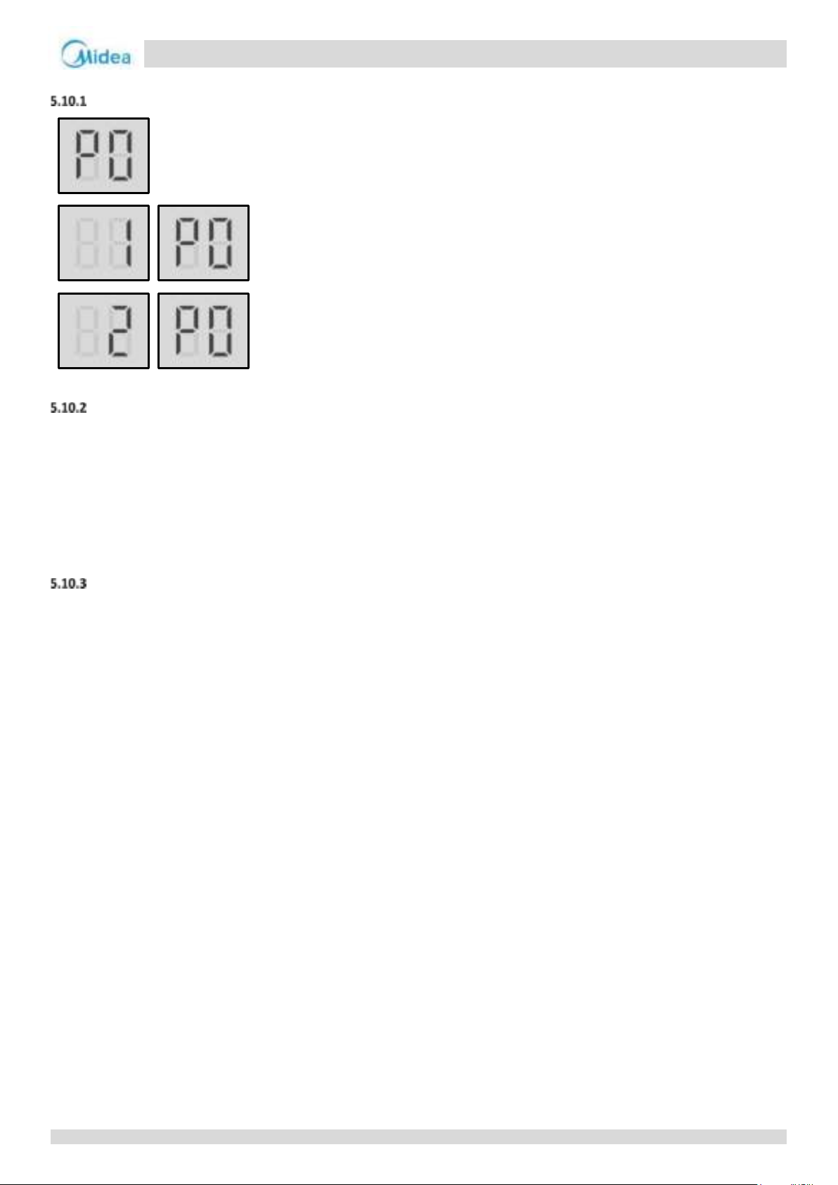
Aqua thermal
Part 4 - Diagnosis and Troubleshooting
5.10 P0 Troubleshooting
Digital display output
Description
Discharge pipe high pressure or discharge temperature switch protection. When the discharge pressure rises above 4.2MPa
or discharge temperature rises above 115°C, the system displays P0 protection and all units stop running. When the
discharge pressure falls below 3.2MPa or discharge temperature fall below 90°C, P0 is removed and normal operation
resumes. When P0 error occurs 3 times in 60 minutes, a manual system restart is required before the system can resume
operation.
Error code is displayed on main PCB and user interface.
Possible causes
High pressure switch or discharge temperature switch not connected properly or has malfunctioned.
Excess refrigerant.
System contains air or nitrogen.
High pressure side blockage.
Poor condenser heat exchange.
Main PCB damaged.
87
Page 87
Aqua thermal
Midea Aqua thermal Service Manual
P0
High pressure switch or discharge
temperature switch connection on main
PCB is loose1
Yes
Ensure High pressure switch or discharge
temperature switch are connected properly
No
High pressure switch or discharge
temperature switch have short-circuited or
failed2
Yes
Replace the high pressure switch or
discharge temperature switch
No
The high pressure side is blocked, caused
by crushed or bent pipe or blocked EXV3
Yes
Inspect the system and fix the error
No
The heat exchange is poor4
Yes
Inspect the system and fix the error
No
The water flow rate is not sufficient in
cooling mode
Yes
Inspect the water system and fix the error
Excess refrigerant or System contains air or
nitrogen
Drain the refrigerant in the system,
vacuum with a vacuum pump, and refill
the nominal weight of refrigerant after
ensuring that the vacuum degree meets
the requirements
Replace outdoor main PCB
Yes
Replace Inverter Module PCB
Procedure
For MC-SU75-RN8L-B and MC-SU140-RN8L-B
No
Notes:
1. Discharge temperature switch connection is port CN27 on the main PCB(labeled 26 in Part 4, 2.2.1 Main PCB component) .High pressure switch connection
is port CN21 on the IPM inverter module PCB;
2. Measure the resistance among the three terminals of the pressure sensor. If the resistance is of the order of mega Ohms or infinite, the pressure sensor
has failed;
3. High pressure side blockage causes discharge temperature to be higher than normal, discharge pressure to be higher than normal and suction pressure to
be lower than normal;
4. In heating mode check water side heat exchanger, water piping, circulator pumps and water flow switch for dirt/blockages. In cooling mode check air side
heat exchanger, fan(s) and air outlets for dirt/blockages.
88
Page 88
Aqua thermal
Part 4 - Diagnosis and Troubleshooting
P0
High pressure switch or discharge
temperature switch connection on main
PCB is loose1
Yes
Ensure High pressure switch or discharge
temperature switch are connected properly
No
High pressure switch or discharge
temperature switch have short-circuited or
failed2
Yes
Replace the high pressure switch or
discharge temperature switch
No
The high pressure side is blocked, caused
by crushed or bent pipe or blocked EXV3
Yes
Inspect the system and fix the error
No
The heat exchange is poor4
Yes
Inspect the system and fix the error
No
The water flow rate is not sufficient in
cooling mode
Yes
Inspect the water system and fix the error
No
Replace outdoor main PCB
For MC-SU90-RN8L-B and MC-SU180-RN8L-B
Notes:
1. High pressure switch connection is port CN20 on the main PCB (labeled 19 in Part 4, 2.2.1 Main PCB component).
2. Measure the resistance among the three terminals of the pressure sensor. If the resistance is of the order of mega Ohms or infinite, the pressure sensor has
failed.
3. High pressure side blockage causes discharge temperature to be higher than normal, discharge pressure to be higher than normal and suction pressure to
be lower than normal.
4. In heating mode check water side heat exchanger, water piping, circulator pumps and water flow switch for dirt/blockages. In cooling mode check air side
heat exchanger, fan(s) and air outlets for dirt/blockages.
89
Page 89
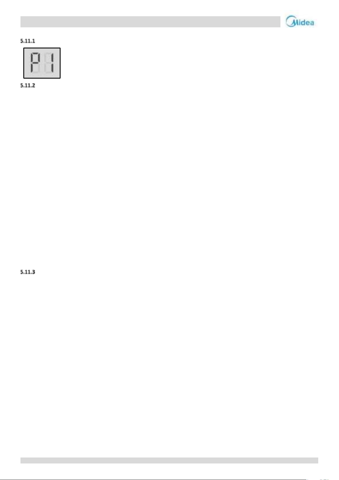
Aqua thermal
Midea Aqua thermal Service Manual
5.11 P1 Troubleshooting
Digital display output
Description
For MC-SU75-RN8L-B and MC-SU140-RN8L-B
P1 indicates suction pipe low pressure protection. When the suction pressure falls below 0.05MPa, the system displays P1
protection and all units stop running. When the pressure rises above 0.15MPa, P1 is removed and normal operation
resumes. When P1 error occurs 3 times in 60 minutes, a manual system restart is required before the system can resume
operation.
P1 another indicates in the standby state or shutdown state, after the compressor stops for 3min, it is determined that the
refrigerant quantity of the refrigerant system of the unit is insufficient through the saturation temperature corresponding to
the high-pressure pressure, the system displays P1 protection, the unit does not start and the protection is not locked;
When the detection pressure returns to above the judgment value, the protection is released and the unit can resume
startup.
P1 the last one indicates during the operation of the compressor of the unit, if the exhaust superheat is too high and lasts
for 30min, report P1 protection first, and then judge the low refrigerant. If the low refrigerant protection is not triggered, P1
protection is removed and the operation is restarted according to the demand.
Error code is displayed on main PCB and user interface.
For MC-SU90-RN8L-B and MC-SU180-RN8L-B
P1 indicates suction pipe low pressure protection. When the suction pressure falls below 0.05MPa, the system displays P1
protection and all units stop running. When the pressure rises above 0.15MPa, P1 is removed and normal operation
resumes. When P1 error occurs 3 times in 60 minutes, a manual system restart is required before the system can resume
operation.
Error code is displayed on main PCB and user interface.
Possible causes
Low pressure switch not connected properly or has malfunctioned.
Insufficient refrigerant.
Low pressure side blockage.
Poor evaporator heat exchange in heating mode.
Insufficient water flow in cooling mode.
Main PCB damaged.
90
Page 90
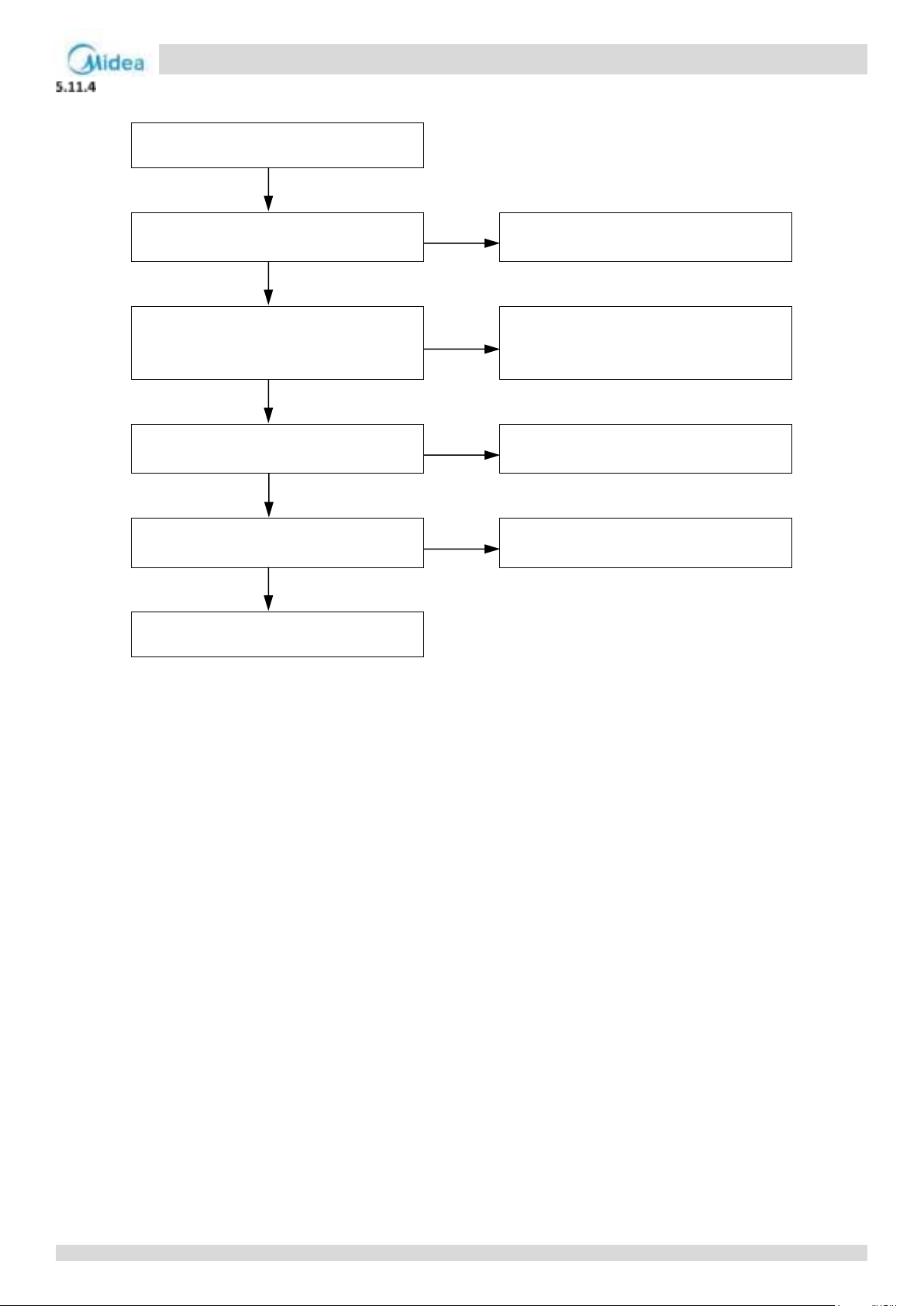
Aqua thermal
Part 4 - Diagnosis and Troubleshooting
P1
Insufficient refrigerant caused by
refrigerant leakage1
Yes
Add refrigerant or inspect the system for
leaks
No
The low pressure side is blocked, caused by
crushed or bent pipe, blocked EXV, or dirty
filter2
Yes
Inspect the system and fix the error. If the
filter is blocked by ice, the piping should be
cleaned
No
The air side heat exchanger heat exchange
is poor in heating mode3
Yes
Inspect the refrigerant system and fix the
error
No
The water flow rate is not sufficient in
cooling mode4
Yes
Inspect the water system and fix the error
No
Replace main PCB
Procedure
Notes:
1. To check for insufficient refrigerant: An insufficiency of refrigerant causes compressor discharge temperature to be higher than normal, discharge and
suction pressures to be lower than normal and compressor current to be lower than normal, and may cause frosting to occur on the suction pipe. These
issues disappear once sufficient refrigerant has been charged into the system.
2. A low pressure side blockage causes compressor discharge temperature to be higher than normal, suction pressure to be lower than normal and
compressor current to be lower than normal, and may cause frosting to occur on the suction pipe. For normal system parameters.
3. Check air side heat exchanger, fan(s) and air outlets for dirt/blockages.
4. Check water side heat exchanger, water piping, circulator pumps and water flow switch for dirt/blockages.
91
Page 91
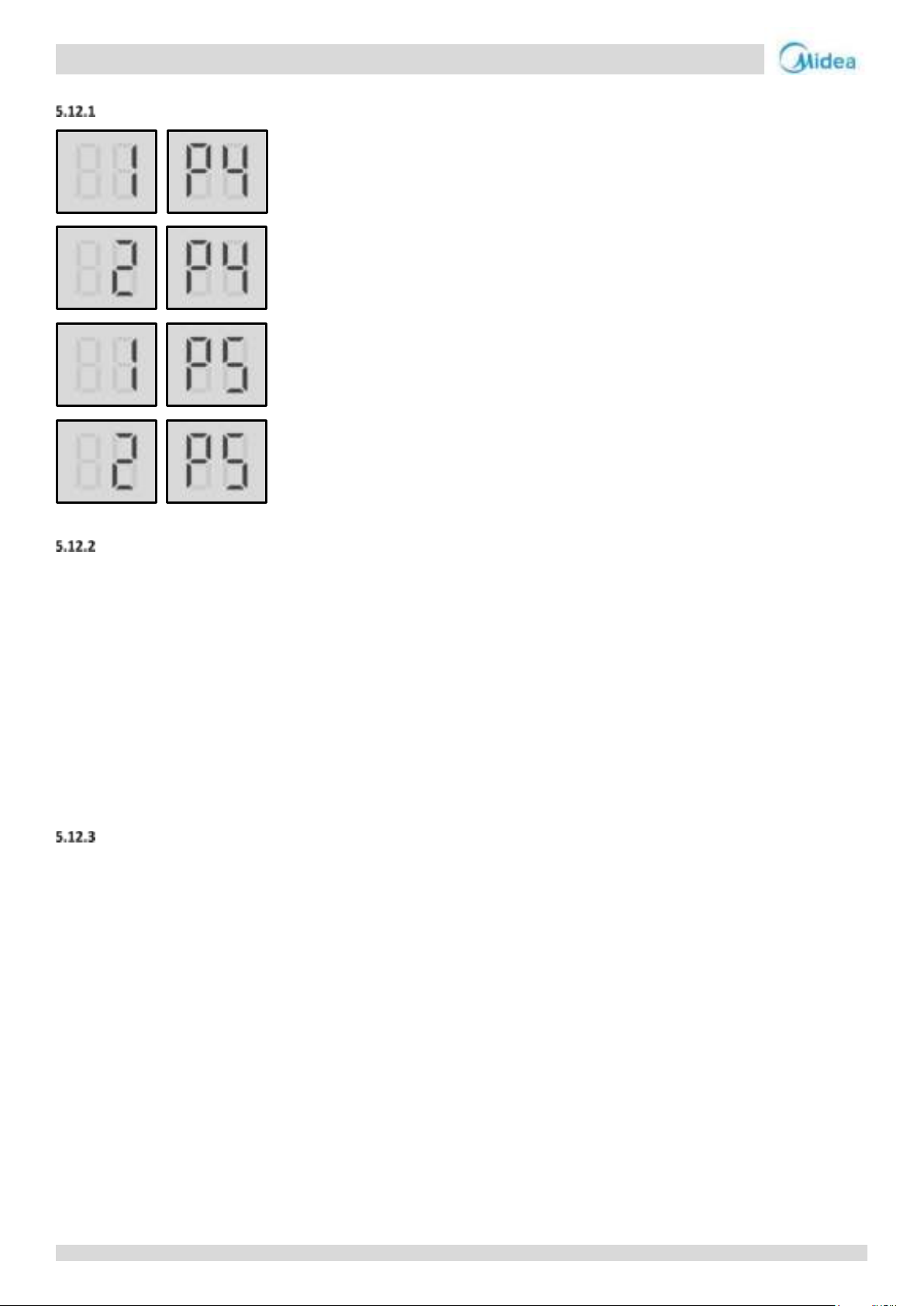
Aqua thermal
Midea Aqua thermal Service Manual
5.12 P4, P5 Troubleshooting
Digital display output
Description
1 P4 indicates system A current protection
2 P4 indicates system A DC bus current protection
1 P5 indicates system B current protection
2 P5 indicates system B DC bus current protection
When the compressor current rises above the protection value 53A/60A (53A for 75/140 model, 60A for90/180 model), or
DC bus current rises above the protection value232A/140A (232A for 75/140 model, 140A for90/180 model), the system
displays P4 or P5 protection and the faulty unit stops running. When the current returns to the normal range, P4 or P5 is
removed and normal operation resumes. When P4 or P5 error occurs 3 times in 60 minutes, a manual system restart is
required before the system can resume operation.
Error code is displayed on main PCB and user interface.
Possible causes
Power supply abnormal.
Poor condenser heat exchange.
High pressure side blockage.
Excess refrigerant.
System contains air or nitrogen.
Inverter module damaged.
Compressor damaged.
Main PCB damaged.
92
Page 92
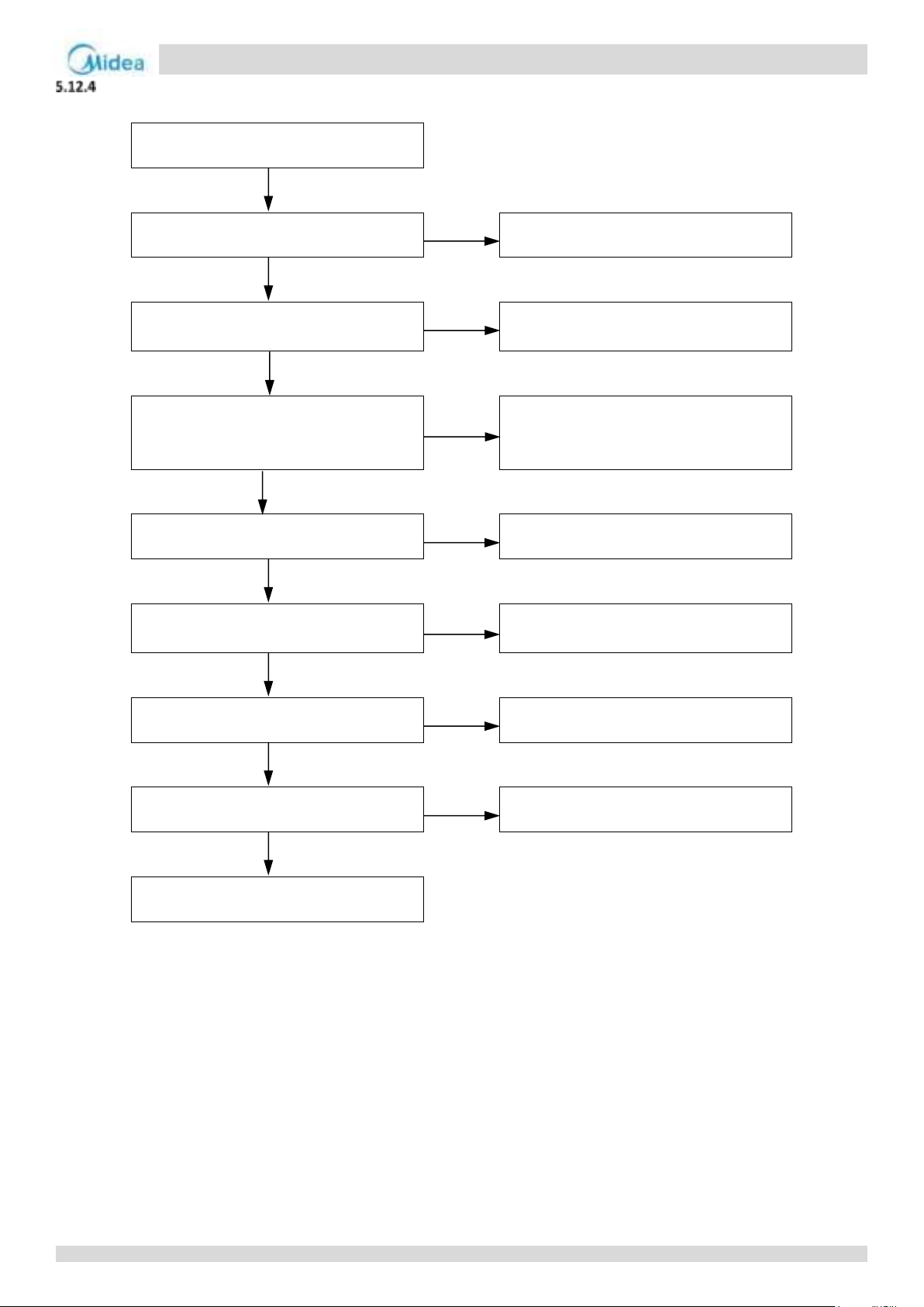
Aqua thermal
Part 4 - Diagnosis and Troubleshooting
P4/P5
The power supply is abnormal
Yes
Check the power supply equipment
No
Excess refrigerant
Yes
Discharge part of the refrigerant. Add oil if
it leaks during discharge refrigerant process
No
System contains air or nitrogen
Yes
Flush all refrigerant then vacuum the
system and recharge refrigerant. Add oil to
the system if it leaks
No
The condenser heat exchange is poor1
Yes
Inspect the system and fix the error
No
The high pressure side is blocked, caused
by crushed or bent pipe or blocked EXV2
Yes
Inspect the system and fix the error
No
Inverter module has short-circuited3
Yes
Replace the inverter module
No
Compressor has malfunctioned4
Yes
Replace the compressor
No
Replace outdoor main PCB
Procedure
Notes:
1. In heating mode check water side heat exchanger, water piping, circulator pumps and water flow switch for dirt/blockages. In cooling mode check air side
heat exchanger, fan(s) and air outlets for dirt/blockages.
2. High pressure side blockage causes discharge temperature to be higher than normal, discharge pressure to be higher than normal and suction pressure to
be lower than normal.
3. Set a multi-meter to buzzer mode and test any two terminals of P N and U V W of the inverter module. If the buzzer sounds, the inverter module has
short-circuited.
4. The normal resistances of the inverter compressor is 0.124Ω(at 20℃ ambient temperature) among U V W and infinite between each of U V W and ground.
If any of the resistances differ from these specifications, the compressor has malfunctioned.
93
Page 93
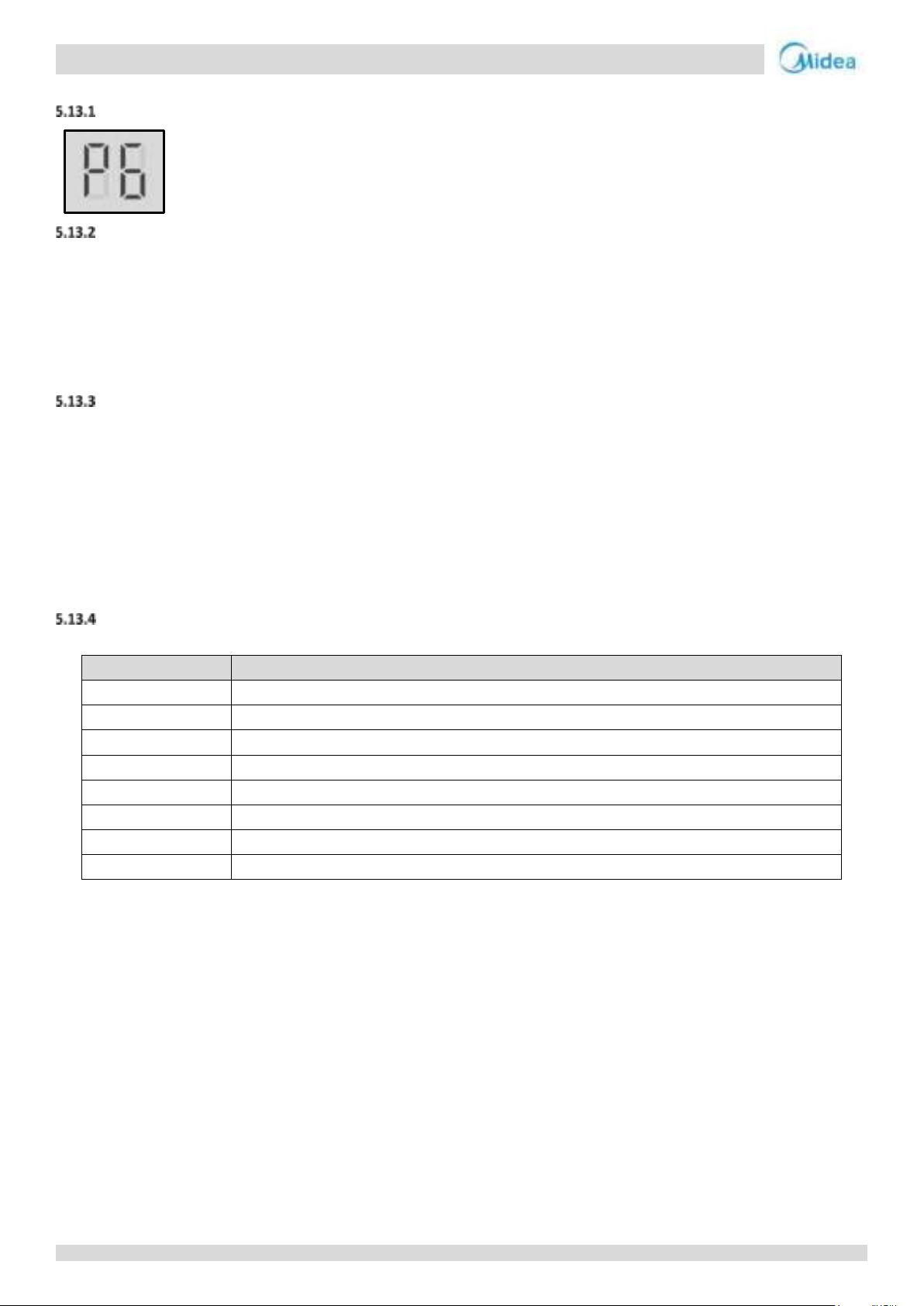
Aqua thermal
Midea Aqua thermal Service Manual
Specific error code1
Content
xL0
Inverter module protection
xL1
DC bus low voltage protection
xL2
DC bus high voltage protection
xL4
MCE error
xL5
Zero speed protection
xL7
Phase sequence error
xL8
Compressor frequency variation greater than 15Hz within one second protection
xL9
Actual compressor frequency differs from target frequency by more than 15Hz protection
Notes:
1. 'x' is a placeholder for the compressor system (compressor and related electrical components), with 1 representing compressor system A and
2 representing compressor system B.
5.13 P6 Troubleshooting (for MC-SU90-RN8L-B and MC-SU180-RN8L-B)
Digital display output
Description
Indicates inverter module failure
When a P6 error occurs, a manual system restart is required before the system can resume operation. The cause of a
P6 error should be addressed promptly in order to avoid system damage.
The faulty unit stops running.
Error code is displayed on the main PCB and user interface.
Possible causes
Inverter module protection
DC bus low or high voltage protection
MCE error
Zero speed protection
Phase sequence error
Excessive compressor frequency variation
Actual compressor frequency differs from target frequency
Specific error codes for XP6 inverter module protection
If P6 error code is displayed, please spot check the specific error code through the wired controller.
The specific error codes xL0, xL1, xL2 and xL4 can also be obtained from the inverter module LED indicators. If an inverter module
error has occurred, LED2 is continuously on and LED1 flashes.
94
Page 94
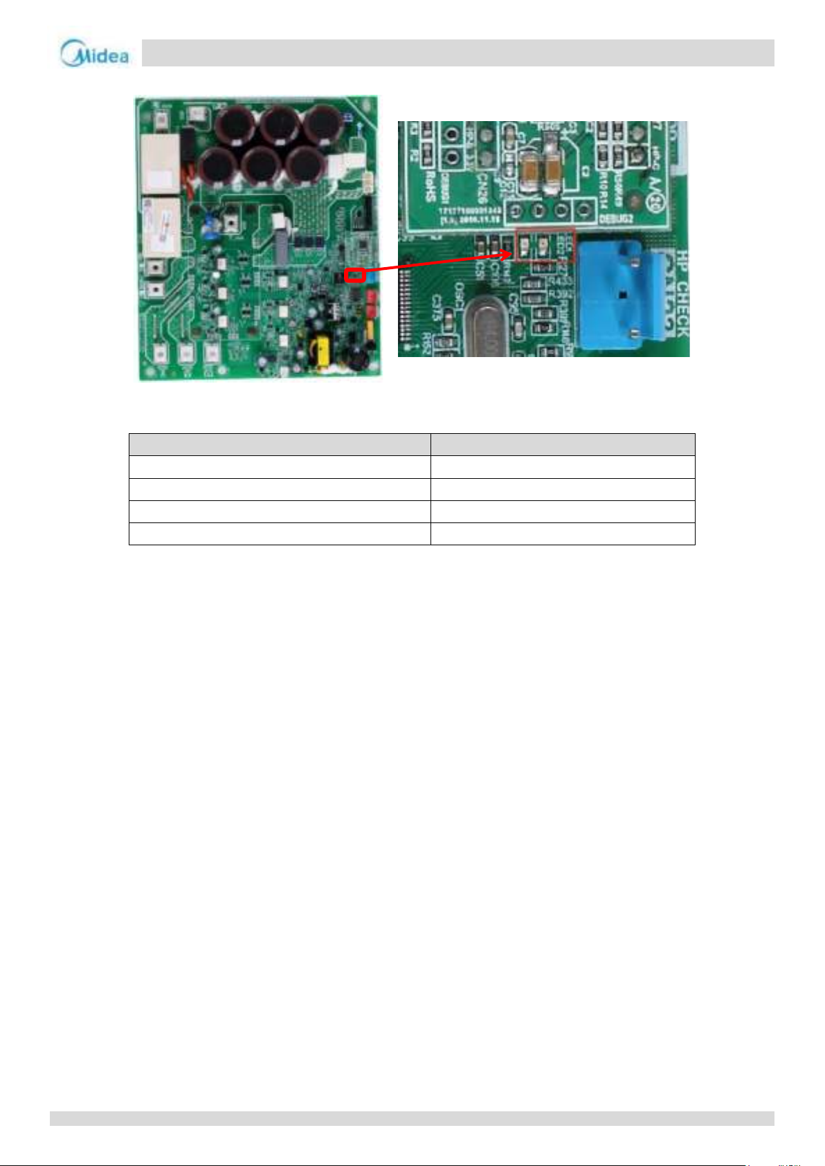
Aqua thermal
Part 4 - Diagnosis and Troubleshooting
LED indicators LED1 and LED2 on inverter module
Errors indicated on LED1
LED1 flashing pattern
Corresponding error
Flashes 8 times and stops for 1 second, then repeats
xL0 - Inverter module protection
Flashes 9 times and stops for 1 second, then repeats
xL1 - DC bus low voltage protection
Flashes 10 times and stops for 1 second, then repeats
xL2 - DC bus high voltage protection
Flashes 12 times and stops for 1 second, then repeats
xL4 - MCE error
95
Page 95
Aqua thermal
Midea Aqua thermal Service Manual
IPM internal rectifier circuit
IPMM internal inverter circuit
L0 protection
The DC bus wire connected incorrectly
1
Ensure the wire is
connected properly
The compressor wiring is connected
incorrectly
Reconnect the cables
based on wiring diagram
Replace the compressor
The inverter module is not well heat
dissipation
The IPM screws is loosen
Fasten IPM
screws again
The silica gel is coated not
well for heat radiation
Coat with silica
gel
The compressor has less than 12 hours
preheating before initial operating
Switch on power again to detect
whether the compressor can start
Refer to “P3 over current protection”
Replace the inverter
module
Ensure enough
preheating time
No
No
No
No
No
No
Yes
Yes
Yes
Yes
Yes
Yes
Yes
No
Yes
Yes
No
No
Disconnect
the power
supply
The resistance between 3 phases of
compressor is over 5Ω
The insulation resistance of
compressor is less than 100kΩ
Refer to P4/P5 troubleshooting
L0: Inverter module protection
Note:
1. Make sure wire connection of CN38 port of compressor inverter module board is firm. Plug or pull out the wire under live working is not allowed.
How to determine whether the compressor module is damaged?
Three phase rectifier measure
Set the multimeter to diode position. After unit power off for 10min, put the black pin on CN5(P_OUT) and put the red pin on CN6(L1)、CN7(L2)、CN11(L3)
respectively. If the voltage value is 0V, it means the three phase rectifier bridge reactor is damaged. Similarly, put the red pin on CN38 (N) and put the black pin
on CN6 (L1), CN7 (L2) and CN11 (L3) respectively. If the voltage value is 0V, it means the three phase rectifier bridge reactor is damaged.
Inverter circuit measure
Set the multimeter to diode position. After unit power off for 10min, put the black pin on CN1(P_in) and put the red pin on CN12(U)、CN13(V)、CN14(W)
respectively. If the voltage value is 0V, it means the IGBT or freewheel diode is damaged. Similarly, put the red pin on CN38 (N) and put the black pin on CN12 (U),
CN13 (V) and CN14 (W) respectively. If the voltage value is 0V, it means the IGBT or freewheel diode is damaged.
96
Page 96
Aqua thermal
Part 4 - Diagnosis and Troubleshooting
L1
The power supply is abnormal
Yes
Check the power supply equipment
No
DC bus voltage(P, N) is abnormal1
No
Change compressor module board
Yes
Power supply for compressor module
board is abnormal
Yes
Check the wire connection between power
supply terminals and filter board; Check the
wire connection between filter board to
compressor module board
No
Wire connection between reactor and
compressor module board is abnormal
Yes
Rewiring according to the wiring diagram
No
Pressure switch is open
Yes
Check whether P0 error appears or high
pressure switch broken
No
Change compressor module board
L1: Low-voltage protection
Note:
1. The normal DC voltage between terminals P and N of CN38 of compressor inverter module board should be 450-650V. When the voltage is lower than 350V.
97
Page 97
Aqua thermal
Midea Aqua thermal Service Manual
L2
The power supply is abnormal
Yes
Check the power supply equipment
No
DC bus voltage(P, N) is abnormal
No
Change compressor module board
Yes
Power supply for compressor module
board is abnormal
Yes
Check the wire connection between power
supply terminals and filter board; Check the
wire connection between filter board to
compressor module board
No
Change compressor module board
L2: High-voltage protection
Note:
1. The normal DC voltage between terminals P and N on inverter module should be 450-650V. When the voltage is higher than 800V, L2 protection will be
appeared.
98
Page 98
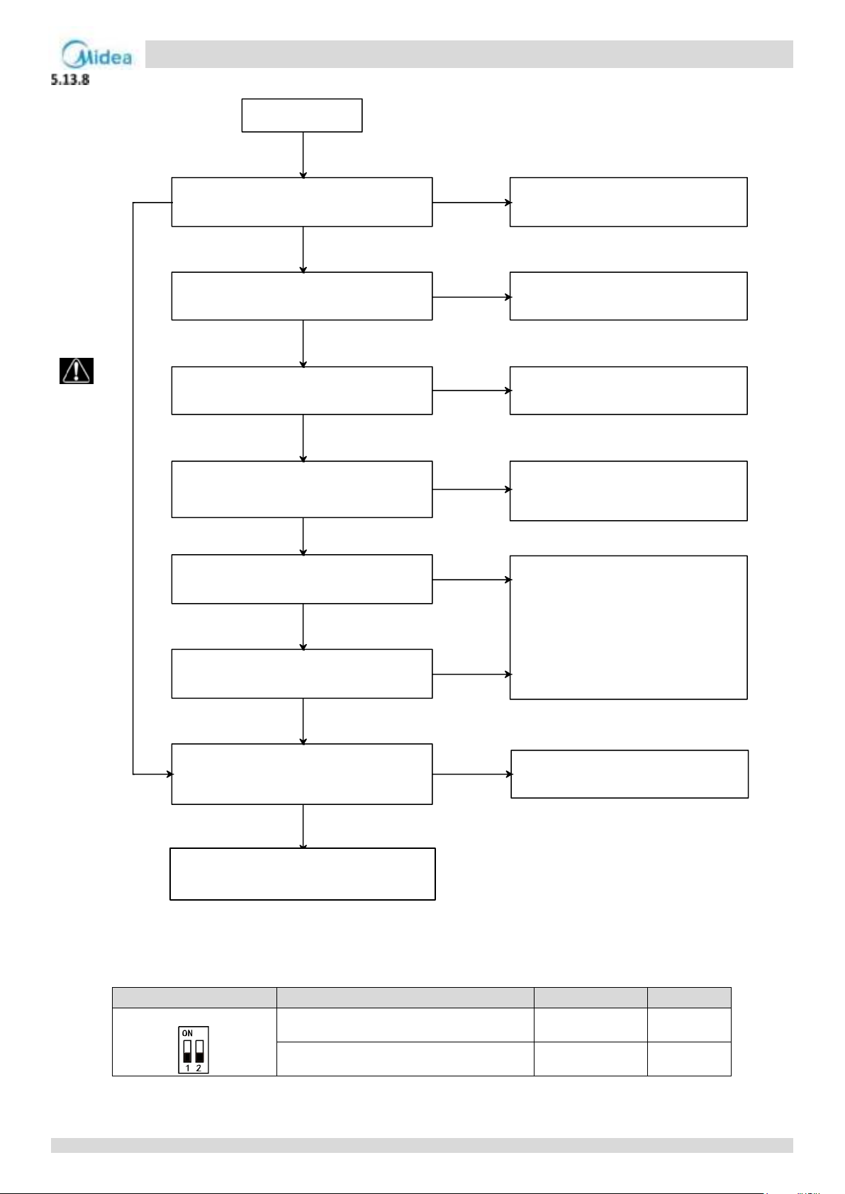
Aqua thermal
Part 4 - Diagnosis and Troubleshooting
Switch
Description
S7-1
S7-2
S7
Compressor A inverter module address setting
OFF
OFF
Compressor B inverter module address setting
OFF
ON
L4 protection
ODU ventilation is not good
Remove barriers from heat
exchanger and air outlet of ODU
ODU stop valves are closed Open the ODU stop valves
Reconnect the cables based on
wiring diagram
The resistance between 3 phases of
compressor is over 5Ω
Replace the compressor
The insulation resistance of
compressor is less than 100Ω
Replace the compressor inverter
board, restart the unit and the error is
solved
Refer to P1 or P3 troubleshooting
No
No
Yes
Yes
Disconnect
the power
supply
Compressor wiring is not properly
Inverter module address setting1 and
discharge temperature sensor wiring is
not properly
Reset the inverter module address
and reconnect the discharge
temperature sensor cables
Yes
Normal
Yes
Yes
Yes
Yes
No
No
No
No
No
Refer to P4/P5 troubleshooting
L4: MCE error
Notes:
1. Compressor inverter module address is set through dial switch S7 on the inverter module. The compressor inverter module A/B location refers to the wiring
diagram
99
Page 99
Aqua thermal
Midea Aqua thermal Service Manual
L7 protection
Compressor wiring is loose
Reconnect cables based on
wiring diagram
An open circuit in the 3-phase U/V/W
of compressor terminals
Replace the compressor
Replace the inverter module
No
No
Yes
Yes
Disconnect the
power supply
L7: Phase sequence error
100
Page 100
Aqua thermal
Part 4 - Diagnosis and Troubleshooting
L8 protection
ODU stop valves are closed Open the ODU stop valves
Reconnect the cables based on
wiring diagram
The resistance between 3 phases of
compressor is over 5Ω
Replace the compressor
The insulation resistance of
compressor is less than 100Ω
Replace the compressor inverter
board, restart the unit and the error is
solved
Refer to P1 or P3 troubleshooting
No
Yes
Disconnect the
power supply
Compressor wiring is not properly
Yes
Normal
Yes
Yes
Yes
No
No
No
No
L9 protection
The compressor has less than 12 hours
preheating before initial operating
Ensure enough preheating time
Yes
Refer to P4/P5 troubleshooting
L8: Compressor frequency variation greater than 15Hz within one second protection
L9: Actual compressor frequency differs from target frequency by more than 15Hz protection
101
 Loading...