

Midea MFGA-60ARDN1-QC2 Service Manual

SERVICE MANUAL
AIRCONDITIONER
FLOOR STANDING TYPE
Model:
MFGA-60ARDN1-QC2

CONTENTS
1. Safety Precautions .............................................................................................................. 1
1.1 Precaution.............................................................................................................................. 1
1.2 Installation .............................................................................................................................. 1
1.3 Caution .................................................................................................................................. 1
1.4 Operational ............................................................................................................................ 2
2. Dimension ............................................................................................................................ 3
2.1 Indoor Unit .................................................................................................................................. 3
2.2 Outdoor Unit ............................................................................................................................... 4
3. Refrigerant cycle diagram .................................................................................................. 5
4 . Wiring diagram ........................................................................................................................ 6
5....Installation details ................................................................................................................... 7
5.1 Installation place ......................................................................................................................... 7
5.2 Installing ..................................................................................................................................... 8
5.3 Refrigerant pipe connection ..................................................................................................... 10
5.3.3 Installation for the first time ................................................................................................... 15
5.3.4 Adding the refrigerant after running the system for many years ........................................... 20
5.3.5 Re-installation while the indoor unit need to be repaired ...................................................... 22
5.3.6 Re-installation while the outdoor unit need to be repaired.................................................... 25
5.4 Drain Pipe of The Indoor Unit ................................................................................................... 28
5.5 Wiring ....................................................................................................................................... 28
5.6 TEST RUN ................................................................................................................................ 28
6....External view and display .................................................................................................... 30
6.1 External view ............................................................................................................................ 30
6.2 CONTROL PANEL ................................................................................................................... 31
7.Operation characteristics ....................................................................................................... 31
8.Electronic function .................................................................................................................. 32
8.1 Main data Introduction ......................................................................................................... 32

8.2 Operation Modes and Functions ......................................................................................... 32
8.3 Other Functions ................................................................................................................... 37
9.Characteristic of temperature sensor ................................................................................... 38
10.Trouble shooting ................................................................................................................... 38
10.1 Protective Function ........................................................................................................... 38
10.2 Self-diagnosis .................................................................................................................... 40
10.3 Troubles and Solutions ..................................................................................................... 40

1. Safety Precautions
1.1 Precaution
To prevent injury to the user or other people and property damage, the following instructions must
be followed.
Incorrect operation due to ignoring instruction will cause harm or damage.
Before service unit, be sure to read this service manual at first.
1.2 Installation
For electrical work, contact the dealer, seller, a qualified electrician, or an Authorized service
center.
Do not disassemble or repair the product by yourself.
Sharp edges could cause injury, be especially careful of the case edges and the fins on the
condenser and evaporator.
Be sure the installation area does not deteriorate with age.
Take care to ensure that power cable could not be pulled out or damaged during operation.
Do not place anything on the power cable.
Do not plug or unplug the power supply plug during operation.
Do not store or use flammable gas or combustible near the product.
When flammable gas leaks, turn off the gas and open a window for ventilation before turn the
product on.
If strange sounds, or small or smoke comes from product. Turn the breaker off or disconnect the
power supply cable as soon as possible.
When the product is soaked (flooded or submerged), contact an Authorized service center.
Be caution that water could not enter the product.
Turn the main power off when cleaning or maintaining the product.
When the product is not be used for a long time, disconnect the power supply plug or turn off the
breaker.
1.3 Caution
Always check for gas (refrigerant) leakage after installation or repair of product.
Install the drain hose to ensure that water is drained away properly.
Keep level even when installing the product.
Do not install the product where the noise or hot air from the outdoor unit could damage the
neighborhoods.
Use two or more people to lift and transport the product.
Do not install the product where it will be exposed to sea wind (salt spray) directly.
1

1.4 Operational
Do not expose the skin directly to cool air for long periods of time. (Do not sit in the draft).
Do not use the product for special purposes, such as preserving foods, works of art, etc. It is a
consumer air conditioner, not a precision refrigerant system.
Do not block the inlet or outlet of air flow.
Use a soft cloth to clean. Do not use harsh detergents, solvents, etc.
Do not touch the metal parts of the product when removing the air filter. They are very sharp.
Do not step on pr put anything on the product. (outdoor units)
Always insert the filter securely. Clean the filter every two weeks or more often if necessary.
Do not insert hands or other object through air inlet or outlet while the product is operated.
Do not drink the water drained from the product.
Use a firm stool or ladder when cleaning or maintaining the product.
Replace the all batteries in the remote control with new ones of the same type. Do not mix old and
mew batteries or different types of batteries.
Do not recharge or disassemble the batteries. Do not dispose of batteries in a fire.
If the liquid from the batteries gets onto your skin or clothes, wash it well with clean water. Do not
use the remote of the batteries have leaked.
2
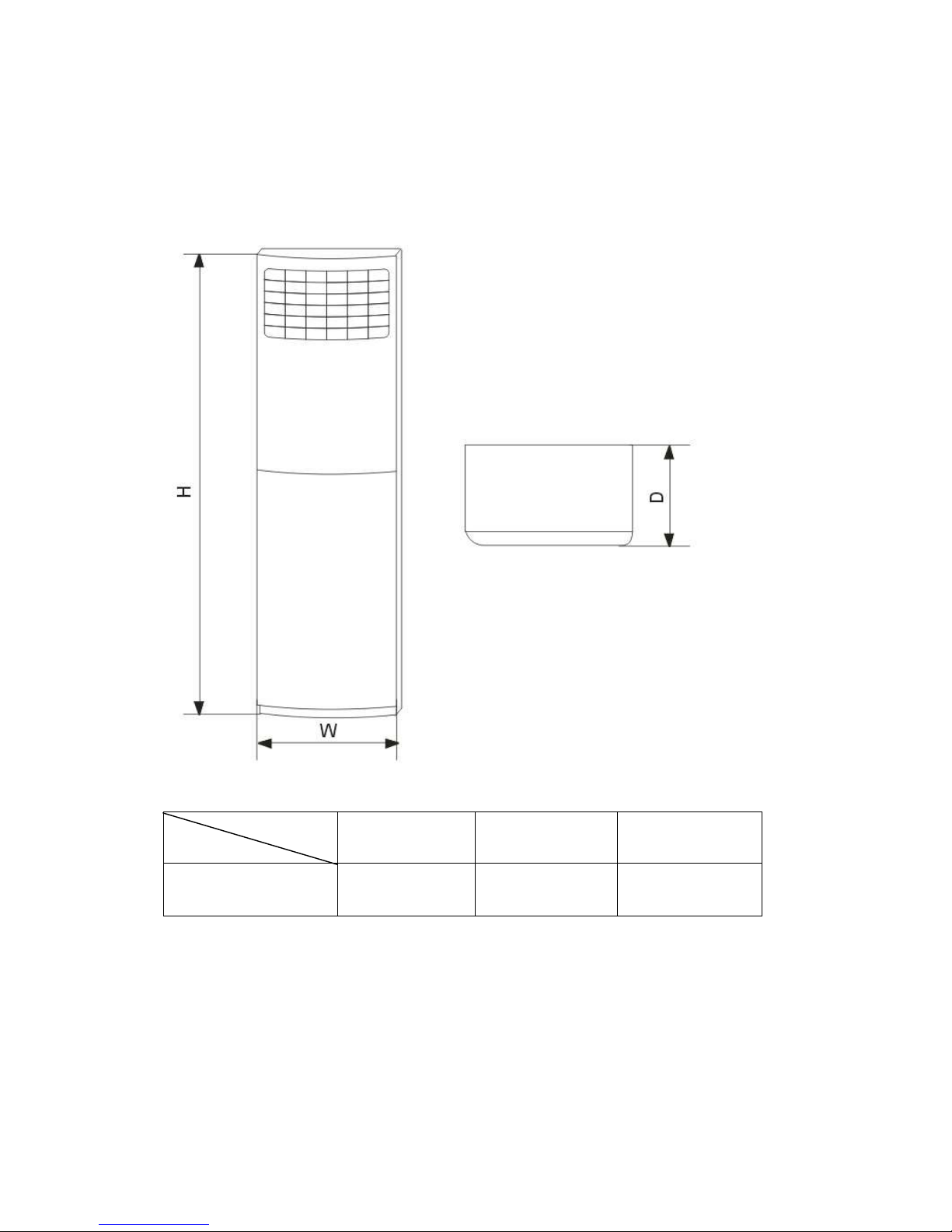
Dimension
2. Dimension
2.1 Indoor Unit
Mode
MFGA-60ARDN1-QC2
W(mm) D(mm) H(mm)
610 390 1925
3
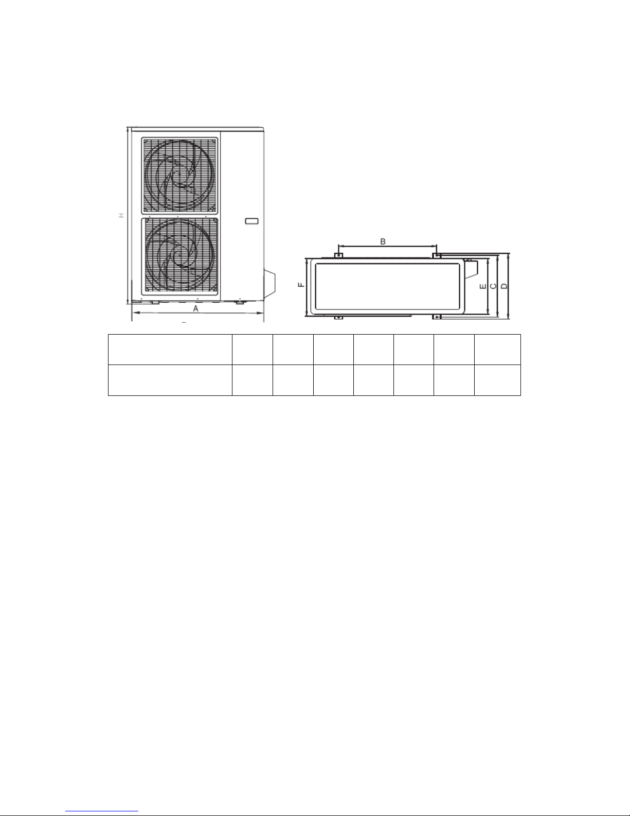
2.2 Outdoor Unit
MODEL A B C D E F H
MOU-60HDN1-R
940 600 376 400 340 360 1245
4
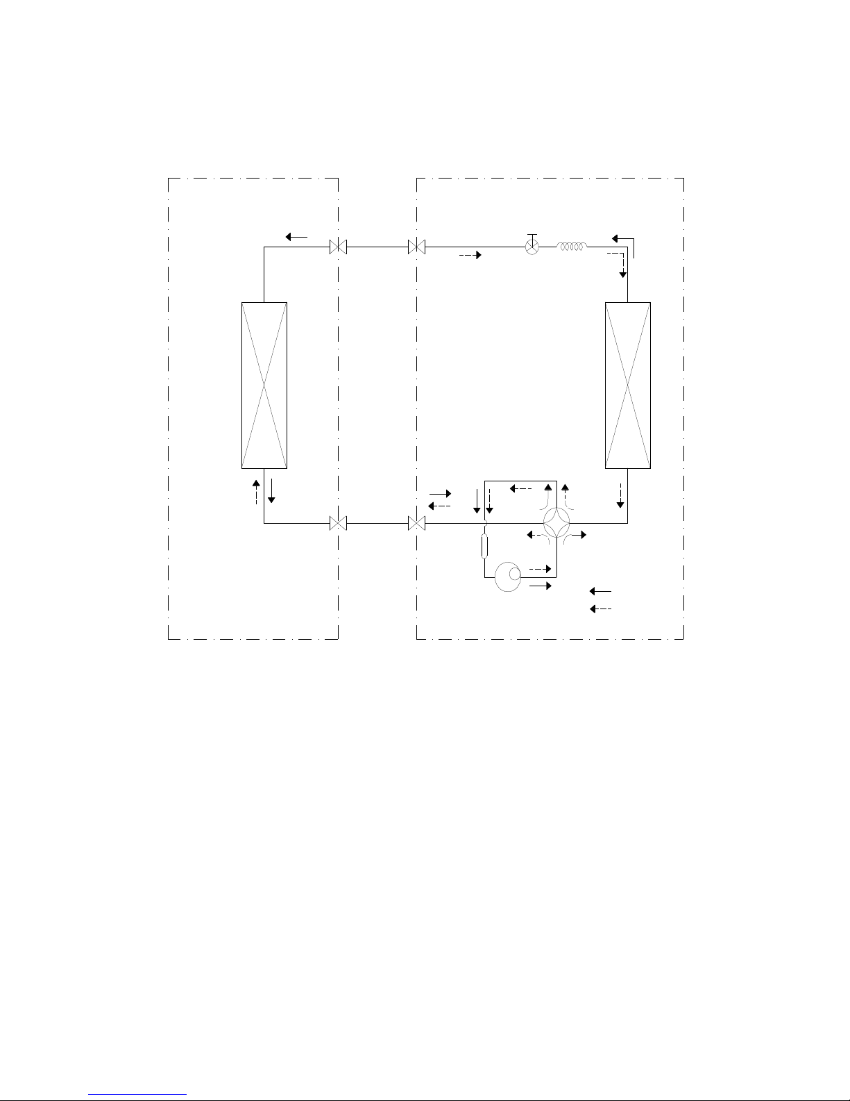
3. Refrigerant cycle diagram
INDOOR OUTDOOR
HEAT
EXCHANGE
(EVAPORATOR)
LIQUID SIDE
2-WAY VALVE
GAS SIDE
3-WAY VALVE
CAPILIARY TUBE
ACCUMULATOR
Electronic Expansion Valve
HEAT
EXCHANGE
(CONDENSER)
REVERSING VALVE
COMPRESSOR
COOLING
HEATING
5
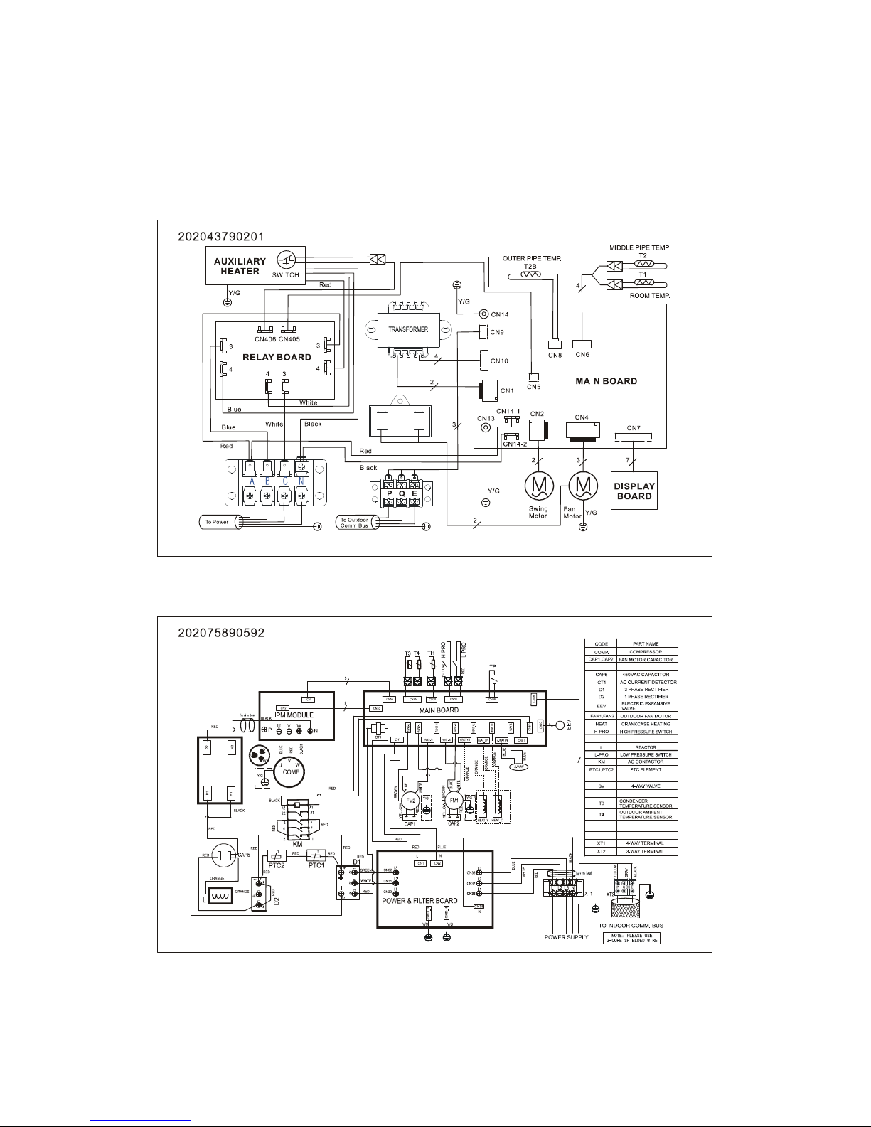
4 . Wiring diagram
MFGA-60ARDN1-QC2
Indoor Unit
Outdoor Unit
6
5....Installation details
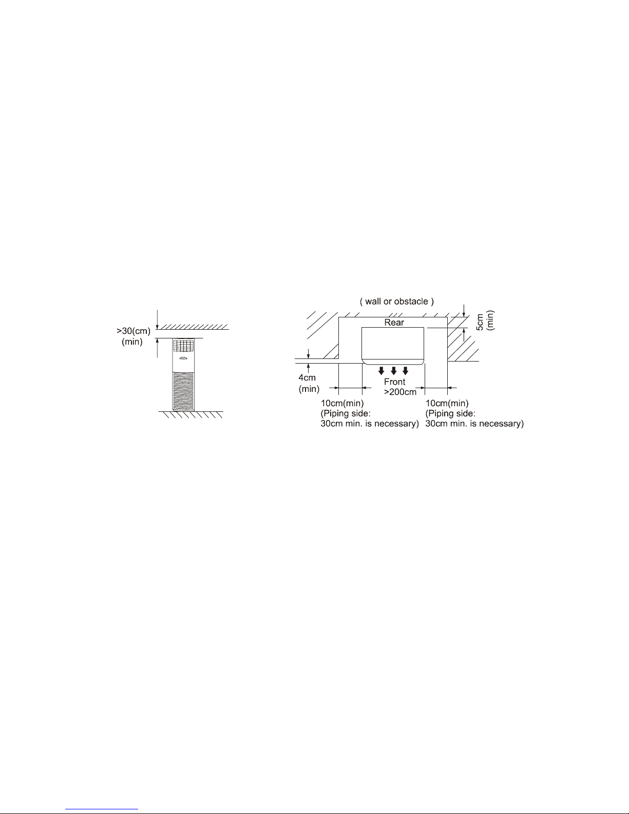
5.1 Installation place
5.1.1 Indoor Unit
a. A place which provides the spaces around the indoor unit as required above in the
diagram.
b. A place where is no obstacle near the inlet and outlet area.
c. A place which can bear the weight of the indoor unit.
d. A place which allows the air filter to be removed downward.
e. A place where the reception range is not exposed to direct sunlight.
f. In the center of the room where possible.
5.1.1.1 Please stand the unit in hard and flat ground;
Please reserve space for installation and maintenance.
5.1.1.2 Please check the elevation difference between the indoor unit and the outdoor unit, the length of
the refrigerant pipe, and the curved places (bend) of the pipe are no more than the following numbers:
Elevation difference: no more than 10M (if the elevation difference between indoor and outdoor unit
is more than 10 meters, it is recommended that the indoor unit be located higher than the outdoor unit.)
Pipe length: no more than 20M.
Bends: no more than 3 places.
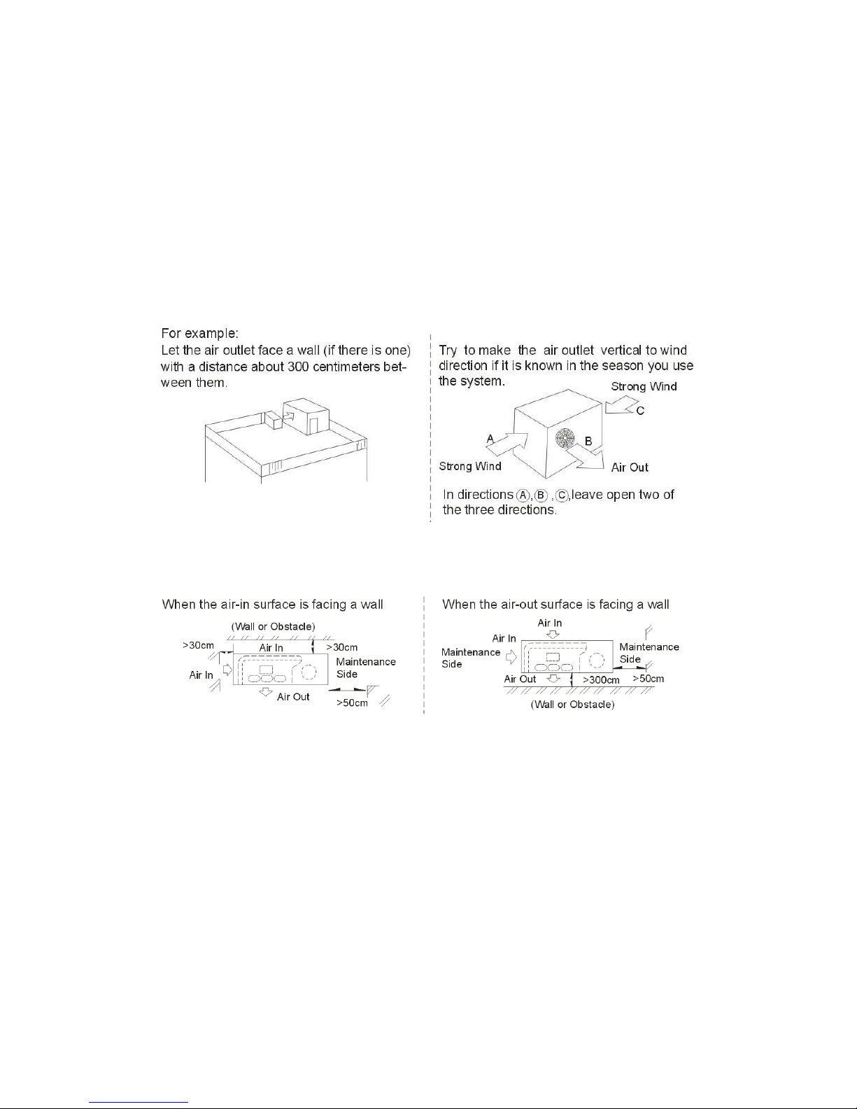
5.1.2 Outdoor Unit
5.1.2.1 Before installing the outdoor unit, you should:
a). Select a place where no direct sunlight or other heat-radioactivity may reach. A sunshade is needed if
it is unavoidable.
b). Select a place that is easy to connect indoor unit's pipe and electric wires.
c). Avoid a place where combustible gas may leak or stay.
d). Keep it in mind that water may drain out of the outdoor unit while in "Heat" mode.
Caution:
Installation in the following places may cause trouble. If it is unavoidable to use in such places, please
consult with the dealer.
7
a. A place full of machine oil.
b. A saline place such as coast.
c. Hot-spring resort.
d. A place full of sulfide gas.
e. A place where there are high frequency machines such as wireless installation, welding
machine, medical facility.
f. A place of special environmental conditions.
5.1.2.2 If the outdoor unit is to be installed on a roof or where no constructions are around, you should
avoid hard wind blows directly to the air outlet, because it may cause trouble for
air-flow shortage.
5.1.2.3 Reserve enough space for installation, maintenance and unit-functioning.
Remove as many obstacles as possible nearby.
5.2 Installing
5.2.1 Indoor Unit:
1. Anti-falling;
To prevent the indoor unit from falling, you must:
a. Pay full attention to the unit because its long outer shape makes it easy to fall;
b. Firmly fix the unit to the wall or in the ground to avoid accidental falling.
8
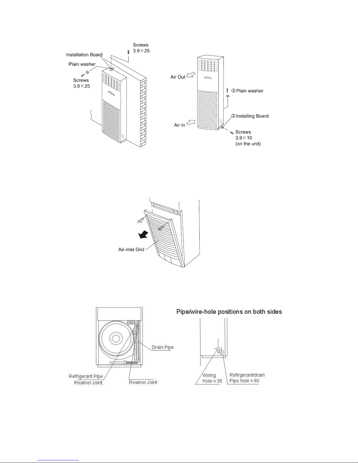
2. Dismounting the air-inlet grid
Please take off the air-inlet grid before connecting the pipes/wires.
Pull down the two knobs on the grid, take off the two screws, then the air-inlet grid goes
free.
3. Take the Pipe Clip off before connecting the pipes and wiring; fit it when these finished.
Use accessories to connect the pipes/wires on both sides and back side.
9
5.2.2 Outdoor Unit:
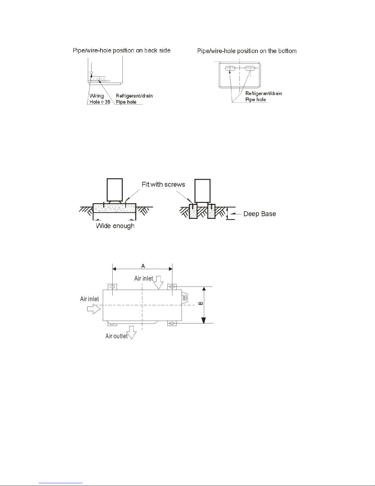
1. Ship the a/c to the installation place originally packed;
2. Be careful while hanging the unit because the center of gravity of the unit is not
centralized;
3. Do not make the angle of inclination more than 45 degrees while shipping;(Avoid
horizontal storage)
4. Be sure the electric insulation work is well done if installed on metal ceiling / wall.
5. Fix the unit feet with bolts (M10/M8). Be sure the unit is fixed strongly enough to
against blast or earthquake.
6. Make a concrete basement to the unit by the following references.
For the value of A and B, please refer to the dimension table.
5.3 Refrigerant pipe connection
5.3.1 Pipe length and the elevation
The correct refrigerant quantity filled in the 5-meter-long pipe of the outdoor unit is marked
on the Product Data Plate. If you have to use longer pipe for every meter plus pipe, the
refrigerant should be added according to the following calculation.
10
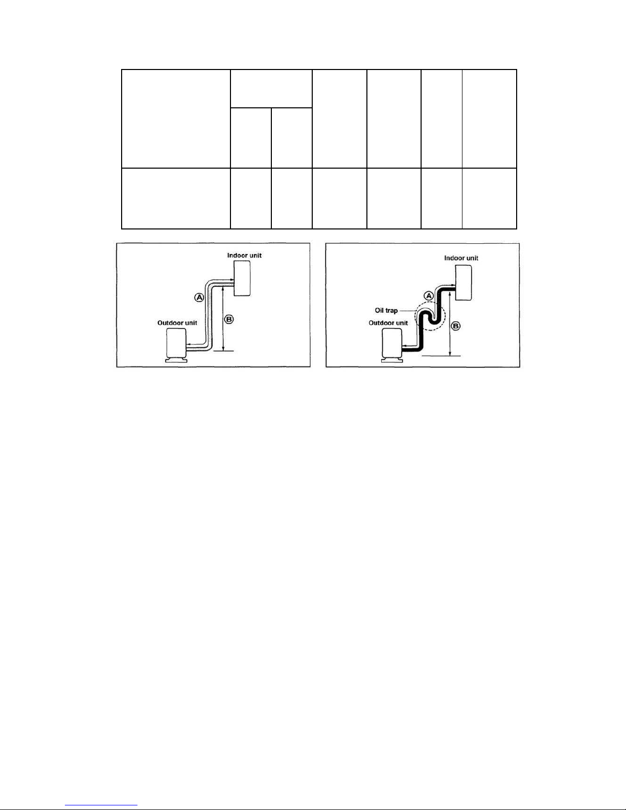
Capacity
Btu/h
MFGA-60ARDN1-QC2
Pipe size
Gas Liquid
5/8’’
(Ф16.0)
3/8’’
(Ф9.52)
Standard
length
(m)
5 15 30 40
Max.
Elevation
B (m)
Max.
Length
A (m)
Additional
refrigerant
(g/m)
Caution:
Capacity is base on standard length and maximum allowance length is base of reliability.
Oil trap should be installed per 5-7 meters.
5.3.2 Piping connection
5.3.2.1 Connecting Of Refrigerant Pipe
a) Only the correctly installing of indoor and outdoor unit done, can the refrigerant pipe
be connected.
b) The cut-off valves are completely close before ex-work. Before connecting the
refrigerant pipe, be careful to check whether the valves are completely close.
c) The connecting procedure of refrigerant pipe: first, unscrew the two valves on the
outdoor unit and the pipe-jointing nut on the indoor unit(please keep them care fully).
Please connect the refrigerant pipe according to the manual, the pipe-jointing nut should
be screw tightly and no leakage. Note: you need two wrenches to make balance.
d) When the connecting of refrigerant pipe is finished, before power on the system, you
11
 Loading...