

Page 1

MCAC-UTSM-2009-03 Contents
Contents i
Part 1 General Information ........................................................................ 1
Part 2 Indoor Units ...................................................................................... 5
Part 3 Outdoor Units ................................................................................. 17
Part 4 Installation ...................................................................................... 36
Part 5 Control ............................................................................................ 56
※The specifications, designs, and information in this book are subject to change without notice for
product improvement.
Page 2

Page 3

MCAC-UTSM-2009-03 General Information
General Information 1
Part 1
General Information
1. Model Names of Indoor/Outdoor Units ....................... 2
2. External Appearance ..................................................... 2
2.1 Indoor Units .................................................................................. 2
2.2 Outdoor Units ............................................................................... 2
3. Nomenclature ................................................................ 3
4. Features ......................................................................... 4
Page 4
Model Names of Indoor/Outdoor Units MCAC-UTSM-2009-03
2 General Information
1. Model Names of Indoor/Outdoor Units
1.1 Indoor Units
Model name Dimension (mm) Net/Gross weight (kg) Power supply
MFA-12HRN1
Width: 700
Height: 600
Depth: 210
15/20 220~240V-1ph-50Hz
MFA-18HRN1
Width: 700
Height: 600
Depth: 210
15/20 220~240V-1ph-50Hz
MFA-12HRN1-Q
Width: 700
Height: 600
Depth: 210
20/25 220~240V-1ph-50Hz
1.2 Outdoor Units
Model name Dimension (mm) Net/Gross weight (kg) Power supply
MON-12HN1
Width: 780
Height: 547
Depth: 250
34/38 220~240V-1ph-50Hz
MON-18HN1
Width: 842
Height: 695
Depth: 324
52/56 220~240V-1ph-50Hz
MON-12HN1-Q
Width: 780
Height: 547
Depth: 250
35/39 220~240V-1ph-50Hz
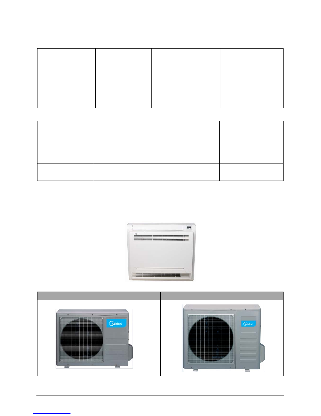
2. External Appearance
2.1 Indoor Units
MFA-12HRN1/MFA-18HRN1/MF A -12HRN1-Q
2.2 Outdoor Units
12,000Btu/h 18,000Btu/h
Page 5
MCAC-UTSM-2009-03 Nomenclature
General Information 3
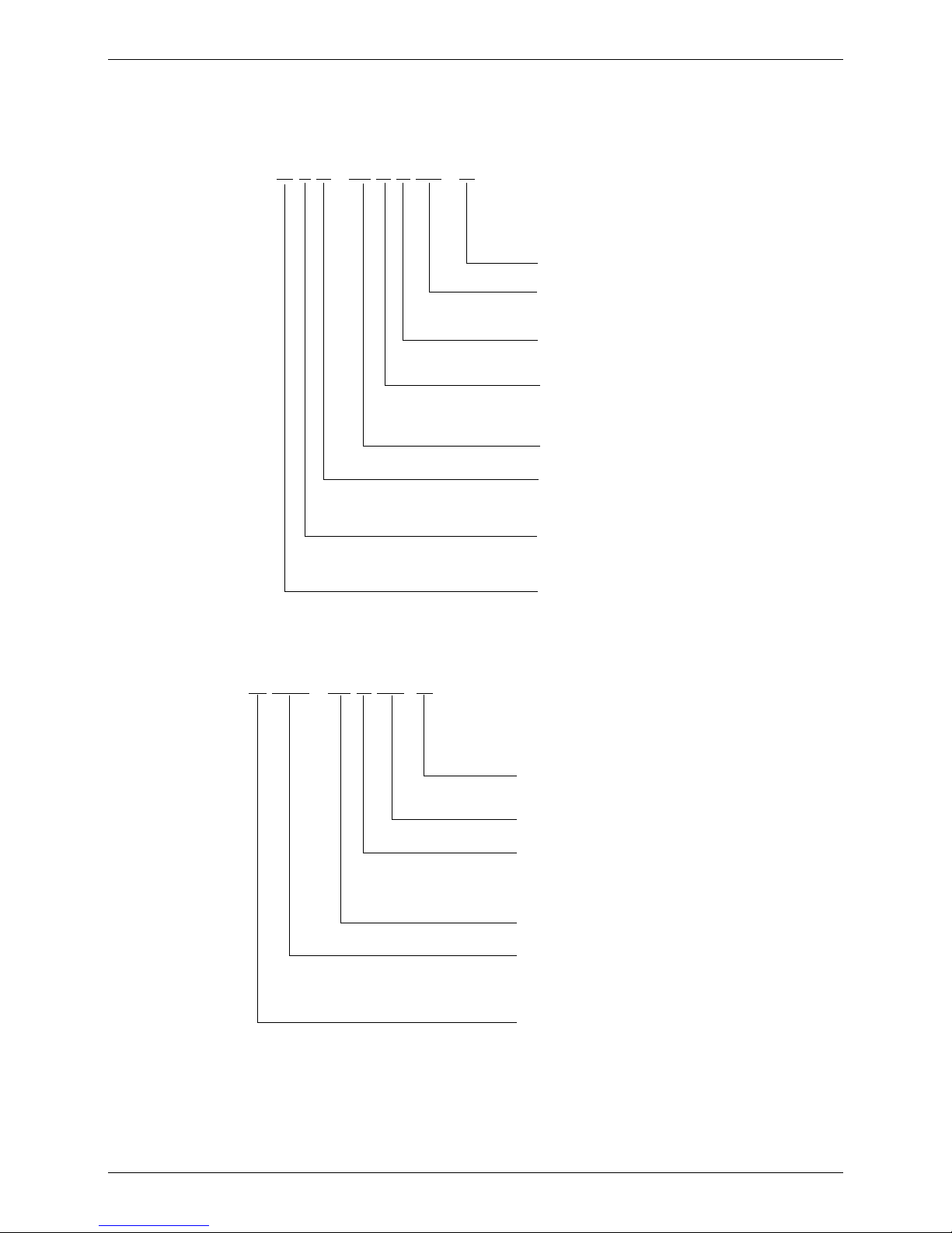
3. Nomenclature
3.1 Indoor Unit
M F A - 12 H R N1 - Q
Q: Quickly Coupling
Refrigerant Type
N1 : R410A
Control Mode
R: Remote Control
Function Code
C: Cooling Only
H: Cooling & Heating
Capacity (×1000Btu/h)
Product Series
A: 1st Designed
Product Category
F: Console Type
Midea
3.2 Outdoor Unit
M O N - 12 H N1- Q
Q: Quickly Coupling
Refrigerant
N1: R410A
Function Code
C: Cooling Only
H: Cooling & Heating
Capacity (×1000Btu/h)
Non-universal Outdoor Unit
O: Outdoor unit
N: Non-universal
Midea
Page 6
Features MCAC-UTSM-2009-03
4 General Information
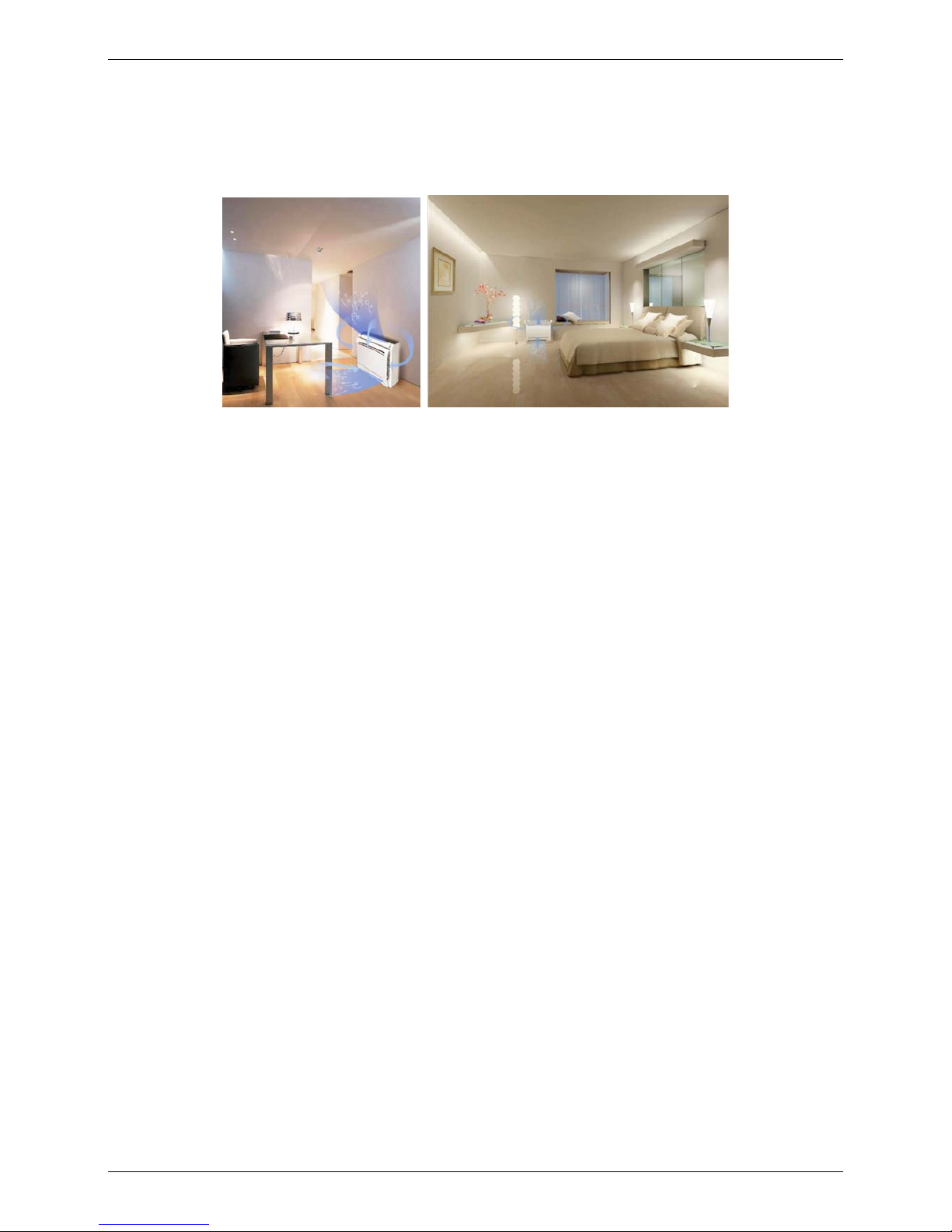
4. Features
1. Achieves set temperature more quickly
——air supplying from top and bottom or from top only
——air inlet from four directions
2. Compact unit body, space saving
——this unit body is very thin and harmonious with room. It is beautiful, elegant and space saving.
——light weight and compact.
3. Flexible installation
——can be used for floor standing or lower wall applications
4. High efficiency filter
——built in Formaldehyde nemesis filter
——active-carbon and biological anti-virus filter is optional.
5. Comfort
——flexible air blow: vertical auto swing and wide angle louvers ensure that warm air reaches the furthest
corners of the room and increase the air flow coverage
——Low noise operation
——Low starting power and precise room temperature adjustment
6. Powerful mode can be selected for rapid cooling or heating.
7. Easy cleaning grille and maintenance
Page 7

MCAC-UTSM-2009-03 Indoor Units
Indoor Units 5
Part 2
Indoor Units
1. Specifications ................................................................ 6
2. Dimensions .................................................................... 7
3. Service Space ................................................................ 7
4. Wiring Diagrams ............................................................ 8
5. Air Velocity and Temperature Distributions ............... 9
6. Capacity Tables ........................................................... 10
7. Electric Characteristics .............................................. 13
8. Sound Levels ............................................................... 13
9. Exploded View ............................................................. 14
10. Accessories ............................................................... 16
Page 8
Specifications MCAC-UTSM-2009-03
6 Indoor Units
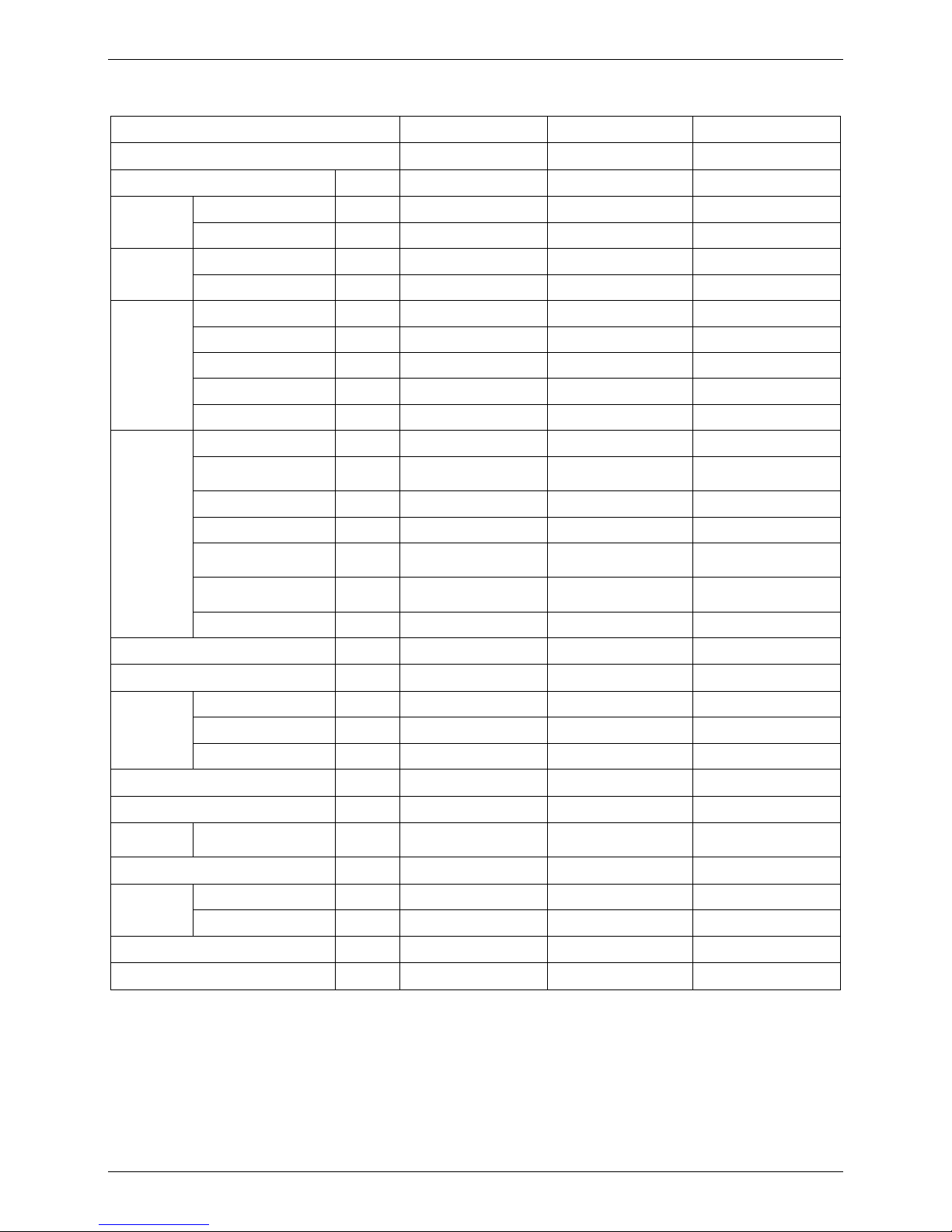
1. Specifications
Model MFA-12HRN1 MFA-18HRN1 MFA-12HRN1-Q
Code 220044000090 220044100280 220044000100
Power supply V-ph-Hz 220~240-1-50 220~240-1-50 220~240-1-50
Cooling
Capacity Btu/h 12000 18000 12000
Input W 1096 1650 1101
Heating
Capacity Btu/h 13380 19600 13300
Input W 1122 1715 1117
Indoor fan
motor
Model RD-280-20-8A RD-280-20-8A RD-280-20-8A
Type DC MOTOR DC MOTOR DC MOTOR
Input W 24.5/19.5/16.8/13/10.5 38/33.5/24.5/15.2 24.5/19.5/16.8/13/10.5
Capacitor uF / / /
Speed(Hi/Mi/Lo) r/min 680/610/560/460/420 890/840/780/680/530 680/610/560/460/420
Indoor coil
Number of rows 2 2 2
Tube pitch(a)×row
pitch(b)
mm 21×13.37 21×13.37 21×13.37
Fin spacing mm 1.3 1.3 1.3
Fin type (code) Hydrophilic aluminum Hydrophilic aluminum Hydrophilic aluminum
Tube outside dia. and
type
mm
Ф7 Inner grooved
copper tube
Ф7 Inner grooved
copper tube
Ф7 Inner grooved
copper tube
Coil length× height ×
width
mm 512×378×26.74 512×378×26.74 512×378×26.74
Number of circuits 2 2 2
Indoor air flow(Hi/Mi/Lo) m3/h 550/490/460/380/350 740/700/640/560/440 550/490/460/380/350
Indoor noise level (sound pressure) dB(A) 35/33/31/27/23 38/35/33/31/29 35/33/31/27/23
Indoor unit
Dimension (W×H×D) mm 700×600×210 700×600×210 700×600×210
Packing (W×H×D) mm 810×710×305 810×710×305 810×710×365
Net/Gross weight kg 15/20 15/20 20/25
Refrigerant type R410A R410A R410A
Design pressure MPa 4.2/2.0 4.2/2.0 4.2/2.0
Refrigerant
piping
Liquid side/ Gas side mm φ6.4/φ12.7 φ6.4/φ12.7 φ6.4/φ12.7
Drainage water pipe diameter mm φ16 φ16 φ16
Connection
wiring
Power wiring mm
2
3×1.5 3×2.5 3×1.5
Signal wiring mm2 4×1.5 4×2.5 4×1.5
Controller R51D/E(standard) R51D/E(standard) R51D/E(standard)
Operation temperature ℃ 17~30 17~30 17~30
Page 9
MCAC-UTSM-2009-03 Dimensions
Indoor Units 7
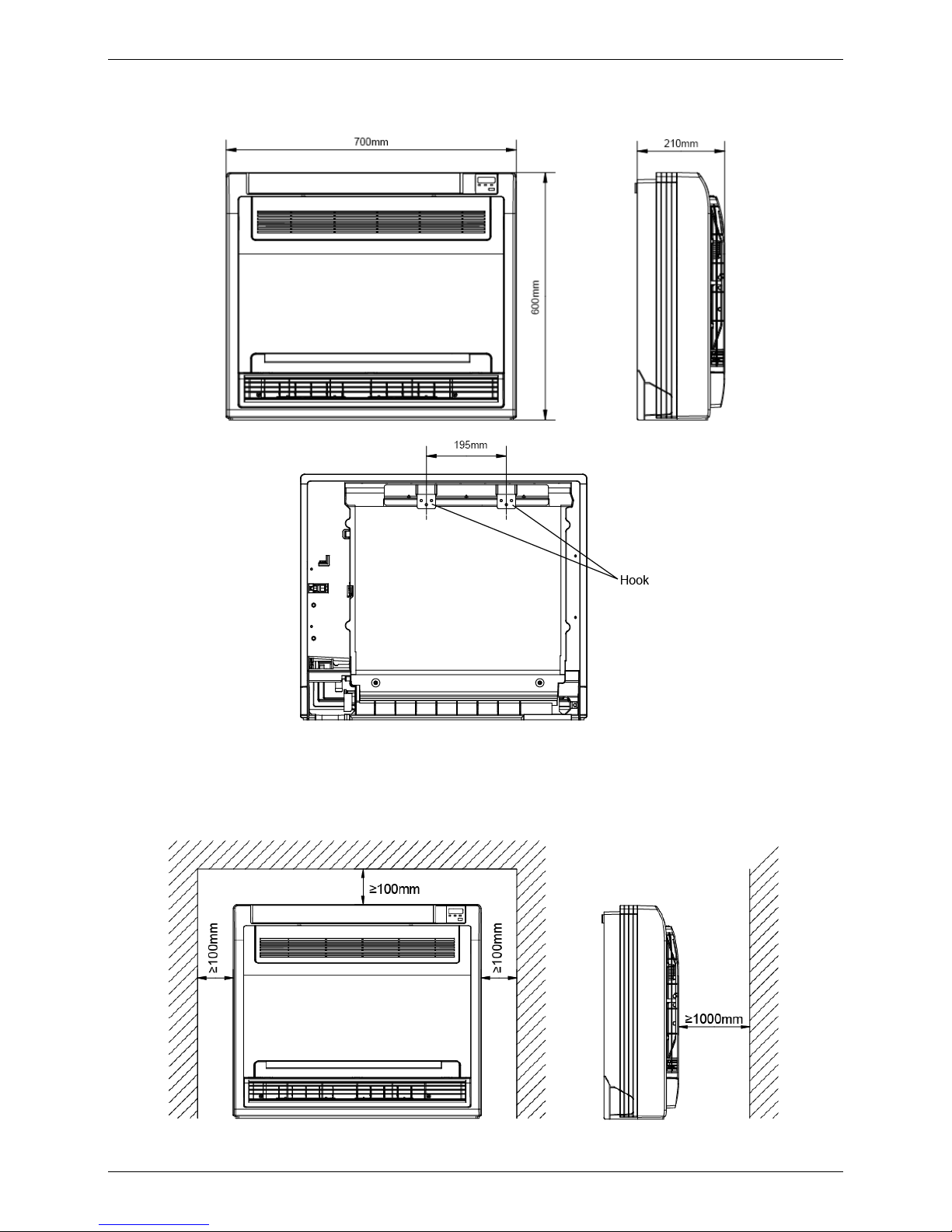
2. Dimensions
3. Service Space
Page 10
Wiring Diagrams MCAC-UTSM-2009-03
8 Indoor Units
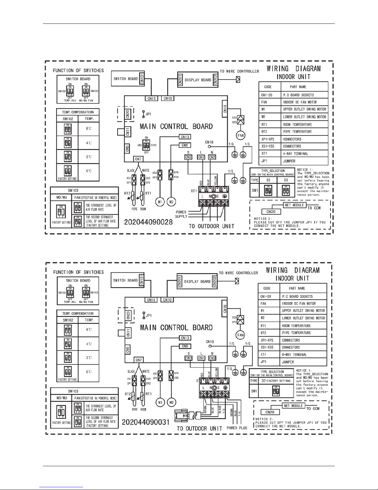
4. Wiring Diagrams
4.1 MFA-12HRN1 MFA-18HRN1
4.2 MFA-12HRN1-Q
Page 11
MCAC-UTSM-2009-03 Air Velocity and Temperature Distributions
Indoor Units 9
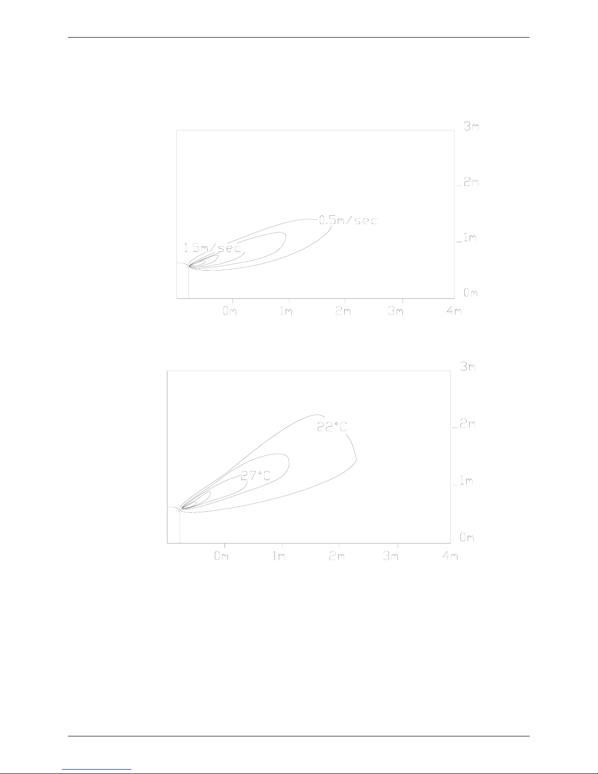
5. Air Velocity and Temperature Distributions
Discharge angle 60
Airflow velocity
Temperature
Page 12

Capacity Tables MCAC-UTSM-2009-03
10 Indoor Units
6. Capacity Tables
6.1 MFA-12HRN1
Cooling capacity
Cooling Outdoor conditions (DB)
Indoor Conditions (kW) 21ºC 28ºC 35ºC 43ºC
21/15ºC DB/WB
TC 3.30 3.14 2.98 2.85
SC 2.44 2.41 2.38 2.39
Input 0.91 0.99 1.03 1.06
24/17ºC DB/WB
TC 3.39 3.23 3.07 2.88
SC 2.54 2.52 2.49 2.42
Input 0.96 1.03 1.07 1.13
27/19ºC DB/WB
TC 3.46 3.30 3.22 2.98
SC 2.56 2.54 2.50 2.44
Input 0.99 1.04 1.096 1.15
32/23ºC DB/WB
TC 3.52 3.39 3.33 3.07
SC 2.99 2.95 2.93 2.86
Input 1.03 1.07 1.15 1.19
Heating capacity
Heating Outdoor conditions
Indoor Conditions (DB) (kW) 24/18ºC DB/WB 7/6ºC DB/WB 2/1ºC DB/WB -5/-6ºC DB/WB
15ºC
TC 4.58 3.95 3.03 2.75
Input 1.21 1.04 0.90 0.84
20ºC
TC 4.44 3.92 2.85 2.68
Input 1.32 1.122 0.99 0.91
27ºC
TC 4.15 3.31 2.68 2.60
Input 1.40 1.21 1.07 0.99
Page 13
MCAC-UTSM-2009-03 Capacity Tables
Indoor Units 11
6.2 MFA-18HRN1
Cooling capacity
Cooling Outdoor conditions (DB)
Indoor Conditions (kW) 21ºC 28ºC 35ºC 43ºC
21/15ºC DB/WB
TC 5.46 5.19 4.93 4.72
SC 4.04 4.00 3.94 3.96
Input 1.32 1.43 1.50 1.55
24/17ºC DB/WB
TC 5.62 5.35 5.09 4.77
SC 4.21 4.18 4.12 4.01
Input 1.40 1.50 1.56 1.64
27/19ºC DB/WB
TC 5.72 5.46 5.30 4.93
SC 4.24 4.20 4.13 4.04
Input 1.43 1.51 1.65 1.67
32/23ºC DB/WB
TC 5.83 5.62 5.51 5.09
SC 4.96 4.89 4.85 4.73
Input 1.50 1.56 1.67 1.74
Heating capacity
Heating Outdoor conditions
Indoor Conditions (DB) (kW) 24/18ºC DB/WB 7/6ºC DB/WB 2/1ºC DB/WB -5/-6ºC DB/WB
15ºC
TC 7.80 6.30 5.16 4.68
Input 1.85 1.59 1.37 1.29
20ºC
TC 7.56 5.74 4.86 4.56
Input 2.02 1.715 1.51 1.39
27ºC
TC 7.08 5.64 4.56 4.44
Input 2.14 1.85 1.63 1.51
Page 14

Capacity Tables MCAC-UTSM-2009-03
12 Indoor Units
6.3 MFA-12HRN1-Q
Cooling capacity
Cooling Outdoor conditions (DB)
Indoor Conditions (kW) 21ºC 28ºC 35ºC 43ºC
21/15ºC DB/WB
TC 3.30 3.14 2.98 2.85
SC 2.44 2.41 2.38 2.39
Input 0.91 0.99 1.03 1.07
24/17ºC DB/WB
TC 3.39 3.23 3.07 2.88
SC 2.54 2.52 2.49 2.42
Input 0.97 1.03 1.08 1.13
27/19ºC DB/WB
TC 3.46 3.30 3.21 2.98
SC 2.56 2.54 2.50 2.44
Input 0.99 1.05 1.101 1.16
32/23ºC DB/WB
TC 3.52 3.39 3.33 3.07
SC 2.99 2.95 2.93 2.86
Input 1.03 1.08 1.16 1.20
Heating capacity
Heating Outdoor conditions
Indoor Conditions (DB) (kW) 24/18ºC DB/WB 7/6ºC DB/WB 2/1ºC DB/WB -5/-6ºC DB/WB
15ºC
TC 4.58 3.70 3.03 2.75
Input 1.21 1.04 0.89 0.84
20ºC
TC 4.44 3.68 2.85 2.68
Input 1.32 1.117 0.98 0.90
27ºC
TC 4.15 3.31 2.68 2.60
Input 1.40 1.21 1.06 0.98
Remark:
TC: Total capacity; kW
SC: Sensible heat capacity; kW
Input: Input power; kW
Page 15
MCAC-UTSM-2009-03 Electric Characteristics
Indoor Units 13
7. Electric Characteristics
Model
Indoor Units Power Supply Indoor Fan Motor
Hz Voltage Min. Max. MCA MFA kW FLA
MFA-12HRN1(-Q) 50 220-240V 198V 254V 0.1 15 0.02 0.08
MFA-18HRN1 50 220-240V 198V 254V 0.156 20 0.02 0.125
Remark:
MCA: Min. Current Amps. (A)
MFA: Max. Fuse Amps. (A)
KW: Fan Motor Rated Output (kW)
FLA: Full Load Amps. (A)
8. Sound Levels
Model
Noise level dB(A)
Highest Higher H M L
MFA-12HRN1/ MFA-12HRN1-Q 35 33 31 27 23
MFA-18HRN1 38 35 33 31 29
Page 16
Exploded View MCAC-UTSM-2009-03
14 Indoor Units
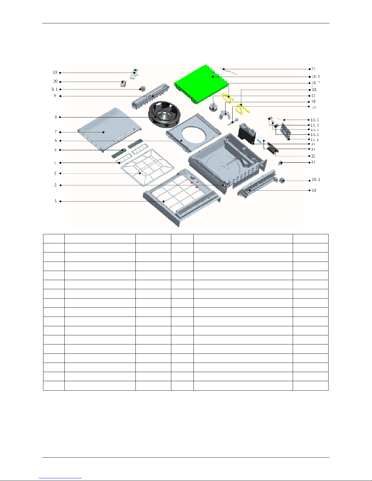
9. Exploded View
9.1 MFA-12HRN1 MFA-18HRN1
No. Part Name Quantity No. Part Name Quantity
1 Panel frame ass'y 1 14.1 Main control board ass'y 1
2 Base ass'y 1 14.2 Wire joint 1
3 Filter 1 14.3 Dial-up board ass'y 1
4 Air fresh net 2 14.4 Display board ass'y 1
5 Formaldehyde-killer 2 14.5 Room temp sensor ass'y 1
6 Air guide ring ass'y 1 15 Wire clamp 1
7 Panel ass'y 1 16 Motor bracket 1
8 Centrifugal fan 1 17 Dc motor 1
9 Air outlet frame ass'y 1 18 Evaporator ass'y 1
9.1 Stepper motor 1 18.1 Output pipe ass'y 1
10 Drainage pan ass'y 1 18.2 Input pipe ass'y 1
10.1 Stepper motor 1 18.3 Evaporator 1
11 Pipe clamp 1 19 Remote controller 1
12 E-Part box cover 1 20 Remote controller holder ass'y 1
13 Insulation washer 1 21 Temp.sensor ass'y 1
14 E-part box ass'y 1
18
Page 17
MCAC-UTSM-2009-03 Exploded View
Indoor Units 15
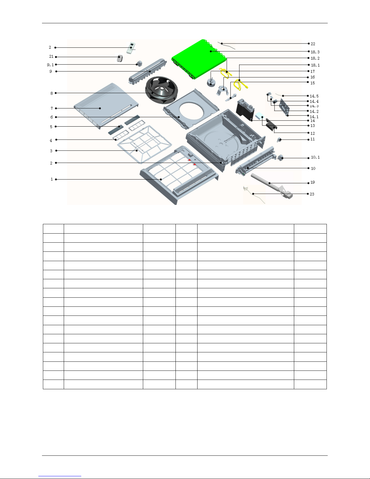
9.2 MFA-12HRN1-Q
No. Part Name Quantity No. Part Name Quantity
1 Panel frame ass'y 1 14.2 Wire joint 1
2 Base ass'y 1 14.3 Dial-up board ass'y 1
3 Filter 1 14.4 Display board ass'y 1
4 Air fresh net 2 14.5 Room temp. sensor ass'y 1
5 Formaldehyde-killer 2 15 Wire clamp 1
6 Air guide ring ass'y 1 16 Motor bracket 1
7 Panel ass'y 1 17 Dc motor 1
8 Centrifugal fan 1 18 Evaporator ass'y 1
9 Air outlet frame ass'y 1 18.1 Output pipe ass'y 1
9.1 Stepper motor 1 18.2 Input pipe ass'y 1
10 Drainage pan ass'y 1 18.3 Evaporator 1
10.1 Stepper motor 1 19 Connection tube ass'y 1
11 Pipe clamp 1 20 Remote controller 1
12 E-Part box cover 1 21 Remote controller holder ass'y 1
13 Insulation washer 1 22 Temp. sensor ass'y 1
14 E-part box ass'y 1 23 Power supply wire 1
14.1 Main control board ass'y 1
Page 18
Accessories MCAC-UTSM-2009-03
16 Indoor Units
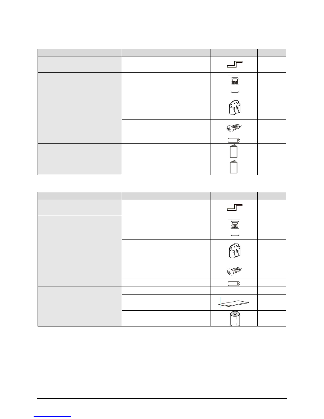
10. Accessories
10.1 MFA-12HRN1/ MFA-18HRN1
Name Shape Quantity
Installation fittings
Hook
2
Remote controller & Its Frame
Remote controller
1
Frame
1
Mounting screw(ST2.9×10-C-H)
2
Alkaline dry batteries (AM4)
2
Others
Installation manual
1
Owner's manual
1
10.2 MFA-12HRN1-Q
Name Shape Quantity
Installation fittings
Hook
2
Remote controller & Its Frame
Remote controller
1
Frame
1
Mounting screw(ST2.9×10-C-H)
2
Alkaline dry batteries (AM4)
2
Others
Installation & Owner's manual / 1
Holding sponge
2
Wrapping tape
1
Page 19

MCAC-UTSM-2009-03 Outdoor Units
Outdoor Units 17
Part 3
Outdoor Units
1. Specifications .............................................................. 18
2. Dimensions .................................................................. 19
3. Service Space .............................................................. 20
4. Piping Diagrams .......................................................... 20
5. Wiring Diagrams .......................................................... 21
6. Electric Characteristics .............................................. 24
7. Operation Limits .......................................................... 24
8. Sound Levels ............................................................... 25
9. Exploded View ............................................................. 26
10. Troubleshooting ........................................................ 29
Page 20

Specifications MCAC-UTSM-2009-03
18 Outdoor Units
1. Specifications
Model MON-12HN1 MON-18HN1 MON-12HN1-Q
Code 220075100200 220075200460 220075100210
Power supply V-ph-Hz 220~240-1-50 220~240-1-50 220~240-1-50
Max. input consumption W 1500 2000 1500
Max. input current A 7.5 12 7.5
Starting current A 29.9 31.8 29.9
Compressor
Model PA140X2C-4FT PA200X2CS-4KU1 PA140X2C-4FT
Type Rotary Rotary Rotary
Brand Midea-TOSHIBA Midea-TOSHIBA Midea-TOSHIBA
Supplier Midea-TOSHIBA Midea-TOSHIBA Midea-TOSHIBA
Capacity Btu/h 11566.68 16787.04 11566.68
Input W 1150 1670 1150
Rated current (RLA) A 5.3 7.81 5.3
Locked rotor Amp (LRA) A 29.9 31.8 29.9
Thermal protector Internal Internal Internal
Capacitor μF 35μF/440-450V 50μF/440-450V 35μF/440-450V
Refrigerant oil ml
ESTEL OIL VG74,
480
ESTER OIL VG74,
750
ESTEL OIL VG74,
480
Outdoor fan
motor
Model YDK24-6F YDK53-6K YDK24-6F
Type AC MOTOR AC MOTOR AC MOTOR
Brand WELLING WELLING WELLING
Input W 58 130 58
Capacitor μF 2.5μF/450V 2.5μF/450V 2.5μF/450V
Speed r/min 800 750 800
Outdoor coil
Number of rows 2 2 2
Tube pitch(a) × row
pitch(b)
mm 21×13.37 22×19.05 21×13.37
Fin spacing mm 1.5 1.6 1.5
Fin type
Hydrophilic
aluminum
Hydrophilic
aluminum
Hydrophilic
aluminum
Tube outside dia. and type mm
Ф7 Inner grooved
copper tube
Ф7.94 Inner grooved
copper tube
Ф7 Inner grooved
copper tube
Coil length × height × width mm 628×504×26.74 630×660×38.1 628×504×26.74
Number of circuits 2 2 2
Outdoor air flow m3/h 1985 2770 1985
Outdoor noise level (sound pressure) dB(A) 52.8 55.5 52.6
Outdoor unit
Dimension(W×H×D) mm 780×547×250 842×695×324 780×547×250
Packing (W×H×D) mm 910×575×335 975×770×405 910×575×335
Net/Gross weight kg 34/38 52/56 35/39
Refrigerant
Type R410A R410A R410A
Charged volume g 1120 1300 1120
Design pressure MPa 4.2/2.0 4.2/2.0 4.2/2.0
Refrigerant
piping
Liquid side/ Gas side mm φ6.4/φ12.7 φ6.4/φ12.7 φ6.4/φ12.7
Max. pipe length m 15 20 —
Max. difference in level m 5 10 —
Ambient temp. ℃
cooling: 21~43;
heating: -5~24
cooling: 21~43;
heating: -5~24
cooling: 21~43;
heating: -5~24
Page 21

MCAC-UTSM-2009-03 Dimensions
Outdoor Units 19
2. Dimensions
2.1 MON-12HN1 MON-12HN1-Q
2.2 MON-18HN1
Page 22

Service Space MCAC-UTSM-2009-03
20 Outdoor Units
3. Service Space
4. Piping Diagrams
T1
T2
Indoor units
Outdoor unit
stop valve
room temp. sensor
evaporator temp. sensor
4-way valve
compressor
condenser temp. sensor
stop valve
one way valve
filter
T3
Throttle capiliary
Page 23

MCAC-UTSM-2009-03 Wiring Diagrams
Outdoor Units 21
5. Wiring Diagrams
5.1 MON-12HN1
Page 24

Wiring Diagrams MCAC-UTSM-2009-03
22 Outdoor Units
5.2 MON-18HN1
Page 25

MCAC-UTSM-2009-03 Wiring Diagrams
Outdoor Units 23
5.3 MON-12HN1-Q
Page 26

Electric Characteristics MCAC-UTSM-2009-03
24 Outdoor Units
6. Electric Characteristics
Model
Outdoor Unit Power Supply Compressor OFM
Hz Voltage Min. Max. MCA TOCA MFA MSC RLA KW FLA
MON-12HN1 50 220~240V 198V 254V 6.6 13 15 29.9 5.3 0.024 0.275
MON-18HN1 50 220~240V 198V 254V 9.8 18 20 31.8 7.81 0.053 0.592
MON-12HN1-Q 50 220~240V 198V 254V 6.6 13 15 29.9 5.3 0.024 0.275
Remark:
MCA: Min. Current Amps. (A)
TOCA: Total Over-current Amps. (A)
MFA: Max. Fuse Amps. (A)
MSC: Max. Starting Amps. (A)
RLA: Rated Locked Amps. (A)
OFM: Outdoor Fan Motor.
FLA: Full Load Amps. (A)
KW: Rated Motor Output (W)
7. Operation Limits
Operation mode Outdoor temperature ( )℃ Room temperature ( )℃
Cooling operation 21~43 17~30
Heating operation -5~24 17~30
10 15 25 30 3520
15
20
25
30
35
40
45
Indoor temperature(℃ WB)
Outdoor temperature(℃ DB)
STD
Cooling
10 15 25 30 3520
-10
-5
0
5
10
15
20
Indoor temperature(℃ DB)
Outdoor temperature(℃ WB)
STD
Heating
25
Page 27

MCAC-UTSM-2009-03 Sound Levels
Outdoor Units 25
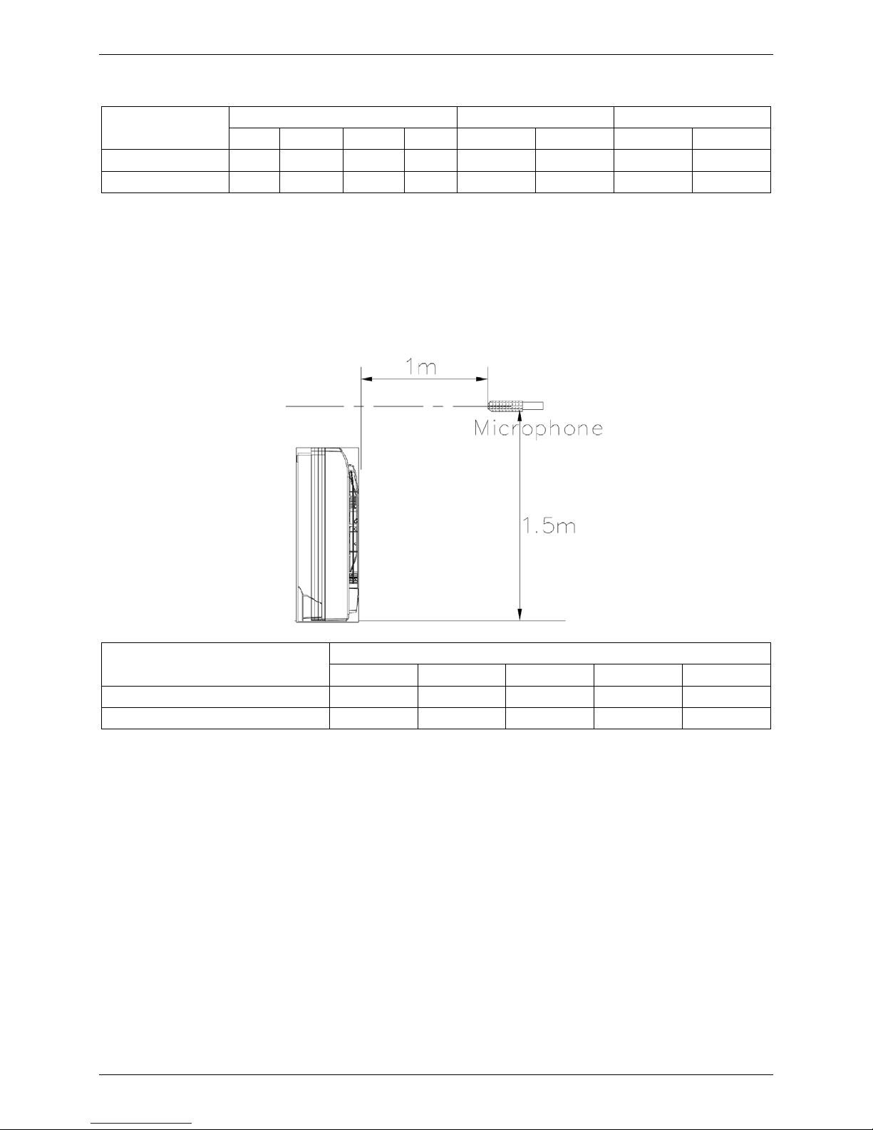
8. Sound Levels
Microphone
Outdoor Unit
H
1.0m
Note: H= 0.5 × height of outdoor unit
Model Noise level dB(A)
MON-12HN1 52.8
MON-18HN1 55.5
MON-12HN1-Q 52.6
Page 28

Exploded View MCAC-UTSM-2009-03
26 Outdoor Units
9. Exploded View
9.1 MON-12HN1
No. Part Name Quantity No. Part Name Quantity
1 Fan motor 1 9 High pressure valve ass'y 1
2 Motor bracket ass'y 1 9.1 High pressure valve 1
3 Rear net 1 9.2 Strainer 1
4 Condenser ass'y 1 9.3 One way valve 1
4.1 Condenser 1 10 Base ass'y 1
4.2 Condenser output pipe 1 11 Grille 1
4.3 Condenser connecting pipe ass'y 1 12 Front panel 1
4.4 Condenser inlet pipe ass'y 1 13 Compressor 1
5 E-part box ass'y 1 14 Net clamp 6
5.1 Wire joint,4p 1 15 Right clapboard 1
5.2 Transformer 1 16 Partition board ass'y 1
5.3 Compressor capacitor 1 17 Left supporter 1
5.4 Motor capacitor 1 18 Small handle 1
5.5 Relay 1 19 Top cover 1
5.6 E-Part box 1 20 Axial flow fan 1
5.7 Main control board ass'y 1 21 Drain hose 1
6 4-way valve ass'y 1 22 Copper nut 1
6.1 4-way valve 1 23 Copper nut 1
6.2 Solenoid 1 24 Sphere pad 1
6.3 Low pressure valve 1 25 Sphere pad 1
7 Big handle 1 26 Temp. sensor ass'y 1
8 Valve plate 1
Page 29

MCAC-UTSM-2009-03 Exploded View
Outdoor Units 27
9.2 MON-18HN1
No. Part Name Quantity No. Part Name Quantity
1 Top cover ass'y 1 18 Grille 1
2 Foam 1 19 Small handle 1
3 Motor bracket ass'y 1 20 E-part box ass'y 1
4 Rear net frame 1 20.1 Wire joint, 4p 1
5 Fan motor 1 20.2 Compressor capacitor 1
6 Axial flow fan 1 20.3 Electric installation board 1
7 Compressor 1 20.4 Motor capacitor 1
8 Partition board ass'y 1 20.5 Main control board ass'y 1
9 Drainage cover 1 20.6 Transformer 1
10 Valve plate 1 20.7 Relay 1
11 Base ass'y 1 21 Drain hose 1
12 High pressure valve ass'y 1 22 Net clamp 8
12.1 Strainer 1 23 Temp. sensor ass'y 1
12.2 One way valve 1 24 Condenser ass'y 1
12.3 High pressure valve 1 24.1 Fluted pipe ass'y 1
13 4-way valve ass'y 1 24.2 Input pipe ass'y 1
13.1 Solenoid 1 24.3 Condenser ass'y 1
13.2 Low pressure valve 1 25 Rear net 1
13.3 4-way valve 1 26 Left holder 1
13.4 Muffler 1 27 Copper nut 1
14 Big handle 1 28 Copper nut 1
15 Rear right clapboard ass'y 1 29 Sphere pad 1
16 Front right clapboard ass'y 1 30 Sphere pad 1
17 Front panel 1
Page 30

Exploded View MCAC-UTSM-2009-03
28 Outdoor Units
9.3 MON-12HN1-Q
No. Part Name Quantity No. Part Name Quantity
1 Fan motor 1 7 Big handle 1
2 Motor bracket ass'y 1 8 Drainage cover 1
3 Rear net 1 9 Valve plate 1
4 Condenser ass'y 1 10 High pressure valve ass'y 1
4.1 Condenser 1 10.1 One way valve 1
4.2 Condenser output pipe 1 10.2 Filter ass'y 1
4.3 Condenser connecting pipe ass'y 1 11 Base ass'y 1
4.4 Condenser inlet pipe ass'y 1 12 Grille 1
5 E-part box ass'y 1 13 Front panel 1
5.1 Connect wiring 1 14 Compressor 1
5.2 Transformer 1 15 Net clamp 6
5.3 Compressor capacitor 1 16 Right clapboard 1
5.4 Motor capacitor 1 17 Partition board ass'y 1
5.5 Relay 1 18 Left supporter 1
5.6 E-Part box 1 19 Small handle 1
5.7 Main control board ass'y 1 20 Top cover 1
6 4-way valve ass'y 1 21 Axial flow fan 1
6.1 4-way valve 1 22 Drain hose 1
6.2 Solenoid 1 23 R410A
6.3 Pipe joint 1 24 Temp. sensor ass'y 1
6.4 Coupling ass'y 1
Page 31

MCAC-UTSM-2009-03 Troubleshooting
Outdoor Units 29
10. Troubleshooting
10.1 Indoor Unit Malfunction
Indoor unit display panel
No. Running lamp Timer lamp Defrosting lamp Malfunction
1 ☆ × × Room temp. sensor checking channel is abnormal
2 × × ☆ Evaporator temp. sensor checking channel is abnormal
3 ☆ ☆ ☆ Condenser temp. sensor checking channel is abnormal
4 × ☆ × In-outdoor unit communication malfunction
5 ☆ ● ☆ DC Fan malfunction
6 ☆ ☆ ● EEPROM malfunction
(× Extinguish, Flash at 5Hz, ☆ ● Light)
1. Running lamp flash at 5Hz
Judge: Room temp. sensor checking channel is abnormal
Validate: Check whether the resistance of the room
temp. sensor is correct according to Annex 1
Yes
Replace the room temp. sensor
Replace the indoor main board
No
Running lamp flash at 5Hz
Page 32

Troubleshooting MCAC-UTSM-2009-03
30 Outdoor Units
2. Defrosting lamp flash at 5Hz
3. Running lamp, Timer lamp, Defrosting lamp all flash at 5Hz
Judge: Evaporator temp. sensor checking channel is abnormal
Validate: Check whether the resistance of the evaporator
temp. sensor is correct according to Annex 1
Yes
Replace the evaporator temp. sensor
Replace the indoor main board
No
Judge: Condenser temp. sensor checking channel is abnormal
Validate: Check whether the resistance of the condenser
temp. sensor is correct according to Annex 1
Yes
Replace the condenser temp. sensor
Replace the PCB
No
Defrosting lamp flash at 5Hz
Running lamp, Timer lamp, Defrosting lamp all flash at 5Hz
Page 33

MCAC-UTSM-2009-03 Troubleshooting
Outdoor Units 31
4. Timer lamp flash at 5Hz
In-outdoor unit communication malfunction
Judge 1: Check whether the wiring of communication line is break off
Yes
Connect the wiring well
Judge 2: Check whether the wiring of L, N and S is wrong
No
Connect the wiring of L, N and S rightly
Replace the PCB
Yes
No
Timer flash at 5Hz
Page 34

Troubleshooting MCAC-UTSM-2009-03
32 Outdoor Units
5. Running lamp and Defrosting lamp flash at 5Hz, the Timer lamp light
6. Running lamp and Timer lamp flash at 5Hz, the Defrosting lamp light
DC fan malfunction
Judge 1: Check whether the wiring of DC fan is break off
Yes
Connect the wiring well
No
Judge 2: Check whether the DC fan is failure
Running lamp and Defrosting lamp flash at 5Hz, the Timer lamp light
EEPROM malfunction
Judge 1: Check whether the EEPROM is inserted well
No
Insert the EEPROM well
Yes
Running lamp and Timer lamp flash at 5Hz, the Defrosting lamp light
Replace the indoor main board
No
Replace the DC fan
Yes
Replace outdoor main board
Judge 2: Check whether the EEPROM is ok
No
Replace the EEPROM
Yes
Page 35

MCAC-UTSM-2009-03 Troubleshooting
Outdoor Units 33
10.2 Outdoor Unit Malfunction
No. LED1 LED2 LED3 Malfunction
1 ☆ × ☆ In-outdoor unit communication malfunction
2 × ☆ ☆ T3 condenser pipe temp. sensor malfunction
× Extinguish, Flash ☆
1. LED1 and LED3 flash
LED1 and LED3 flash
In-outdoor unit communication malfunction
Judge 1: Check whether the wiring of communication line is break off
Yes
Connect the wiring well
Judge 2: Check whether the wiring of L, N and S is wrong
No
Connect the wiring of L, N and S rightly
Replace the PCB
Yes
No
Page 36

Troubleshooting MCAC-UTSM-2009-03
34 Outdoor Units
2. LED2 and LED3 flash
T3 condenser pipe temp. sensor malfunction
Check whether the temp. sensor is connected well
No
Connect it well
LED2 and LED3 flash
Check whether the resistance of the temp. sensor is correct
accordin
g
to Annex 1
Yes
Replace the temp. sensor
Replace the PCB
No
Yes
Page 37

MCAC-UTSM-2009-03 Troubleshooting
Outdoor Units 35
Appendix Indoor Temp. and Pipe Temp. Sensor Resistance Value Table (℃--K)
℃
K Ohm
℃
K Ohm
℃
K Ohm
℃
K Ohm
-20
115.266
20
12.6431
60
2.35774
100
0.62973
-19
108.146
21
12.0561
61
2.27249
101
0.61148
-18
101.517
22
11.5000
62
2.19073
102
0.59386
-17
96.3423
23
10.9731
63
2.11241
103
0.57683
-16
89.5865
24
10.4736
64
2.03732
104
0.56038
-15
84.2190
25
10.000
65
1.96532
105
0.54448
-14
79.3110
26
9.55074
66
1.89627
106
0.52912
-13
74.5360
27
9.12445
67
1.83003
107
0.51426
-12
70.1698
28
8.71983
68
1.76647
108
0.49989
-11
66.0898
29
8.33566
69
1.70547
109
0.48600
-10
62.2756
30
7.97078
70
1.64691
110
0.47256
-9
58.7079
31
7.62411
71
1.59068
111
0.45957
-8
56.3694
32
7.29464
72
1.53668
112
0.44699
-7
52.2438
33
6.98142
73
1.48481
113
0.43482
-6
49.3161
34
6.68355
74
1.43498
114
0.42304
-5
46.5725
35
6.40021
75
1.38703
115
0.41164
-4
44.0000
36
6.13059
76
1.34105
116
0.40060
-3
41.5878
37
5.87359
77
1.29078
117
0.38991
-2
39.8239
38
5.62961
78
1.25423
118
0.37956
-1
37.1988
39
5.39689
79
1.21330
119
0.36954
0
35.2024
40
5.17519
80
1.17393
120
0.35982
1
33.3269
41
4.96392
81
1.13604
121
0.35042
2
31.5635
42
4.76253
82
1.09958
122
0.3413
3
29.9058
43
4.57050
83
1.06448
123
0.33246
4
28.3459
44
4.38736
84
1.03069
124
0.32390
5
26.8778
45
4.21263
85
0.99815
125
0.31559
6
25.4954
46
4.04589
86
0.96681
126
0.30754
7
24.1932
47
3.88673
87
0.93662
127
0.29974
8
22.5662
48
3.73476
88
0.90753
128
0.29216
9
21.8094
49
3.58962
89
0.87950
129
0.28482
10
20.7184
50
3.45097
90
0.85248
130
0.27770
11
19.6891
51
3.31847
91
0.82643
131
0.27078
12
18.7177
52
3.19183
92
0.80132
132
0.26408
13
17.8005
53
3.07075
93
0.77709
133
0.25757
14
16.9341
54
2.95896
94
0.75373
134
0.25125
15
16.1156
55
2.84421
95
0.73119
135
0.24512
16
15.3418
56
2.73823
96
0.70944
136
0.23916
17
14.6181
57
2.63682
97
0.68844
137
0.23338
18
13.9180
58
2.53973
98
0.66818
138
0.22776
19
13.2631
59
2.44677
99
0.64862
139
0.22231
Page 38

Installation MCAC-UTSM-2009-03
36 Installation
Part 4
Installation
1. Installation Place ......................................................... 37
2. Installation of Indoor Unit ........................................... 38
3. Installation of outdoor unit ......................................... 40
4. Installation of the Connecting Pipe ........................... 41
5. Connect the Drain Pipe ............................................... 48
6. Wiring ........................................................................... 50
7. Test Operation ............................................................. 55
Page 39

MCAC-UTSM-2009-03 Installation Place
Installation 37
1. Installation Place
1.1 The indoor Unit
5. There is enough room for installation and maintenance.
6. The air outlet and the air inlet are not impeded, and the influence of external air is the least.
7. The air flow can reach throughout the room.
8. The connecting pipe and drainpipe could be extracted out easily.
9. There is no direct radiation from heaters
1.2 The Outdoor Unit
1. There is enough space for installation and maintenance.
2. The air outlet and the air inlet are not impeded, and can not be reached by strong wind.
3. The place is dry and ventilative.
4. The support is flat and horizontal and can stand the weight of the outdoor unit. And no additional noise
or vibration.
5. Your neighborhood will not feel uncomfortable with the noise or expelled air.
6. There is no leakage of combustible gas.
7. It is easy to install the connecting pipe or cables.
Caution:
Don’t install the air conditioner in the following locations:
a. There exists petrolatum.
b. There is salty air surrounding (near the coast).
c. There is caustic gas (the sulfide, for example) existing in the air (near a hot spring).
d. The Volt vibrates violently (in the factories).
e. In buses or cabinets.
f. In kitchen where it is full of oil gas.
g. There is strong electromagnetic wave existing.
h. There are inflammable materials or gas.
i. There is acid or alkaline liquid evaporating.
j. Other special conditions
1.3 Notes before Installation
1. Select the correct carry-in path.
2. Move this unit as originally packaged as possible.
3. If the air conditioner is installed on a metal part of the building, it must be electrically insulated according
to the relevant standards to electrical appliances.
Page 40

Installation of Indoor Unit MCAC-UTSM-2009-03
38 Installation
2. Installation of Indoor Unit
2.1 Service Space
The indoor unit should be installed in a location that meets the following requirements:
There is enough room for installation and maintenance. (Refer to the following figure )
The outlet and the inlet are not impeded, and the influence of external air is the least.
The air flow can reach throughout the room.
The connecting pipe and drainpipe could be extracted out easily.
There is no direct radiation from heaters.
Caution: Keep indoor unit, outdoor unit, power supply wiring and transmission wiring at least 1 meter away
from televisions and radios. This is to prevent image interference and noise in those electrical appliances.
(Noise may be generated depending on the conditions under which the electric wave is generated, even if
1 meter is kept.)
Page 41

MCAC-UTSM-2009-03 Installation of Indoor Unit
Installation 39
2.2 Installation the main body
z Fix the hook with tapping screw onto the wall
z Hang the indoor unit on the hook.
(The bottom of body can touch with floor or suspended, but the body must install vertically.)
Page 42

Installation of outdoor unit MCAC-UTSM-2009-03
40 Installation
3. Installation of outdoor unit
3.1 Necessary space for Installation and Maintenance
If possible, please remove the obstacles nearby to prevent the performance from being impeded by too little
of air circulation. The minimum distance between the outdoor unit and obstacles described in the installation
chart doesn’t mean that the same is applicable to the situation of an airtight room. Leave open two of the
three directions (M, N, P).
3.2 Moving and Installing
1. Since the gravity center of the unit is not at its physical center, so please be careful when lifting it with a sling.
2. Never hold the inlet of the outdoor unit to prevent it from deforming.
3. Do not touch the fan with hands or other objects.
4. Do not lean it more than 45°, and do not lay it sidelong.
5. Make concrete foundation according to the specifications of the outdoor units.
6. Fasten the feet of this unit with bolts firmly to prevent it from collapsing in case of earthquake or strong wind.
Page 43

MCAC-UTSM-2009-03 Installation of the Connecting Pipe
Installation 41
4. Installation of the Connecting Pipe
Caution:
For your safety, always wear safety eye wear and work gloves when connecting the pipes.
4.1 MFA-12HRN1-Q (Quick connecter)
Remove the water tray before performing the connection.
Page 44

Installation of the Connecting Pipe MCAC-UTSM-2009-03
42 Installation
To connect the couplings:
Step 1: Ensure that the handle on the male coupling is in a reclined position away from the mating male
coupling.
Step 2: Retract the “Release Sleeve” on female coupling, insert the male coupling located on the indoor unit
into the female coupling.
Step 3:
Release the “Release Sleeve” to the lock the male coupling into places.
Step 4: Fold the male coupling handle towards the female coupling half and push until the handle seals
behind the “Release Sleeve” and flat against the entire coupling assembly.
Frost proof processing
For prevent that the connect pipe produce frost to drip, you need to inhibit the holding sponge on the connect
pipe of inside door, and then bundle it by wrapping tape.
Page 45

MCAC-UTSM-2009-03 Installation of the Connecting Pipe
Installation 43
4.2 MFA-12HRN1and MFA-18HRN1
Check whether the height drop between the indoor unit and outdoor unit, the length of refrigerant pipe, and
the number of the bends meet the following requirements:
Capacity(Btu/h) 12000 18000
The max. height drop 5m 10m
The length of refrigerant pipe Less than 15m Less than 20m
The number of bends Less than 5 Less than 8
4.2.1 The Procedure of Connecting Pipes
Caution:
z All field piping must be provided by a licensed refrigeration technician and must comply with the
relevant local and national codes.
z Do not let air, dust, or other impurities fall in the pipe system during the time of installation.
z The connecting pipe should not be installed until the indoor and outdoor units have been fixed already.
z Keep the connecting pipe dry, and do not let moisture in during installation.
z Execute heat insulation work completely on both sides of the gas piping and the liquid piping. Otherwise,
this can sometimes result in water leakage.
1. Drill a hole in the wall (suitable just for the size of the wall conduit), then set on the fittings such as
the wall conduit and its cover.
2. Bind the connecting pipe and the cables together tightly with binding tapes.
3. Pass the bound connecting pipe through the wall conduct from outside. Be careful of the pipe
allocation to do on damage to the tubing.
4. Connect the pipes.
5. Expel the air with a vacuum pump. Refer to "How to expel the air with a vacuum pump" for details.
6. Open the stop valves of the outdoor unit to make the refrigerant pipe connecting the indoor unit with
the outdoor unit in fluent flow.
7. Check the leakage. Check all the joints with the leak detector or soap water.
8. Cover the joints of the connecting pipe with the soundproof / insulating sheath (fittings), and bind it
well with the tapes to prevent leakage.
Caution:
Be sure to with insulating materials cover all the exposed parts of the flare pipe joints and refrigerant
pipe on the liquid-side and the gas-side. Ensure that there is no gap between them.
Incomplete insulation may cause water condensation.
Page 46

Installation of the Connecting Pipe MCAC-UTSM-2009-03
44 Installation
How to take indoor unit apart to connect the pipes
1. Open the front panel
Slide the two stoppers on the left and right sides until they click.
2. Remove the front panel
Remove the string.
Allowing the front panel to fall forward will enable you to remove it.
Page 47

MCAC-UTSM-2009-03 Installation of the Connecting Pipe
Installation 45
3. Remove the face plate
Remove the four screws.
Opening bottom of face plate for a angle that is 30 degree, then the top of face plate will be take up.
How to take outdoor unit apart to connect the pipes
Remove the water tray
How to connect the pipes
1. Flaring:
Cut a pipe with a pipe cutter.
Page 48

Installation of the Connecting Pipe MCAC-UTSM-2009-03
46 Installation
Insert a flare nut into a pipe and flare the pipe.
Refer to the following table for the dimension of flare nut spaces.
Pipe gauge Tightening torque
Flare dimension (A)
Flare shape
Min Max
Φ6.4
15
~16N.m
(153
~163kgf.cm)
8.3 8.7
Φ9.5
25
~26N.m
(255
~265 kgf.cm)
12.0 12.4
Φ12.7
35
~36 N.m
(357
~367 kgf.cm)
15.4 15.8
Φ15.9
45
~47 N.m
(459
~480 kgf.cm)
18.6 19.0
Φ19.1
65
~67 N.m
(663
~684 kgf.cm)
22.9 23.3
2. Connect the indoor unit at first, then the outdoor unit.
z Bend the tubing in proper way. Do not harm to them.
z The bending angle should not exceed 90°.
z Bending position is preferably in the middle of the bendable pipe. The larger the bending radius the
better it is.
z Do not bend the pipe more than three times.
z When connecting the flare nut, coat the flare both inside and outside with either oil or ester oil and
initially tighten by hand 3 or 4 turns before tighting firmly.
z Be sure to use both spanner and torque wrench together when connecting or disconnecting pipes to the unit.
Caution:
z Too large torque will harm the bell mouthing and too small will cause leakage.
z After the connecting work is finished, be sure to check that there is no gas leak.
Page 49

MCAC-UTSM-2009-03 Installation of the Connecting Pipe
Installation 47
How to expel the air with a vacuum pump
Stop valve operation introduction
1. Opening stop valve
1) Remove the cap and turn the valve counter clock-wise with the hexagon wrench.
2) Turn it until the shaft stops. Do not apply excessive force to the stop valve. Doing so may break the
valve body, as the valve is not a backseat type. Always use the special tool.
3) Make sure to tighten the cap securely.
2. Closing stop valve
1) Remove the cap and turn the valve clockwise with the hexagon wrench.
2) Securely tighten the valve until the shaft contacts the main body seal.
Make sure to tighten the cap securely.
For the tightening torque, refer to the table below.
Tightening torque N.M (Turn clockwise to close)
Stop Valve size Shaft (valve body) Cap (Valve lid) Maintenance nut
φ6.4
5.4~6.6
Hexagonal
wrench 4 mm
13.5~16.5
11.5
~13.9
φ9.5
φ12.7 8.1~9.9 18~22
φ15.9 13.5~16.5
Hexagonal
wrench 6mm
23~27
φ22.2
27~33
Hexagonal
wrench 10 mm
36~44
φ25.4
Caution:
z Always use a charge hose for service port connection.
z After tightening the cap, check that no refrigerant leaks are present
Using the vacuum pump
1) Loosen and remove the maintenance nuts of stop valves A and B, and connect the charge hose of the
manifold valve to the service port of stop valve A. (Be sure that stop valves A and B are both closed)
2) Connect the joint of the charge hose with the vacuum pump.
3) Open the Lo-lever of the manifold value completely.
4) Turn on the vacuum pump. At the beginning of pumping, loosen the maintenance nut of stop valve B a
little to check whether the air comes in (the sound of the pump changes, and the indicator of compound
meter turns below zero). Then fasten the maintenance nut.
5) When the pumping has finished, close the Lo-lever of the manifold valve completely and turn off the
vacuum pump. Make pumping for 15 minutes or more and check that the compound meter indicates
-76cmHg (-1×10
5
Pa)
6) Loosen and remove the cap of stop valves A and B to open stop valve A and B completely, then fasten
the cap.
7) Disassemble the charge hose from the service port of stop valve A, and fasten the nut.
Page 50

Connect the Drain Pipe MCAC-UTSM-2009-03
48 Installation
4.2.2 Additional Refrigerant Charge
Caution:
z Refrigerant cannot be charged until field wiring has been completed.
z Refrigerant may only be charged after performing the leak test and the vacuum pumping.
z When charging a system, care shall be taken that its maximum permissible charge is never exceeded,
in view of the danger of liquid hammer.
z Charging with an unsuitable substance may cause explosions and accidents, so always ensure that the
appropriate refrigerant is charged.
z Refrigerant containers shall be opened slowly.
z Always use protective gloves and protect your eyes when charging refrigerant.
The outdoor unit is factory charged with refrigerant. Calculate the added refrigerant according to the
diameter and the length of the liquid side pipe of the outdoor unit/indoor unit connection.
R(g) D(mm)
L(m)
Φ6.4 Φ9.5
Less than 5m (One-way) — —
Added refrigerant when over 5m (One-way) 11g/m×(L-5) 30g/m×(L-5)
R(g): Additional refrigerant to be charged
L(m): The length of the refrigerant pipe(one-way)
D(mm): Liquid side piping diameter
5. Connect the Drain Pipe
5.1 Install the drainpipe of the indoor unit
The outlet has PTI screw bread, Please use sealing materials and pipe sheath(fitting) when connecting PVC
pipes.
Caution:
1) The drain pipe of indoor unit must be heat insulated, or it will condense dew, as well as the connections
of the indoor unit.
2) Hard PVC binder must be used for pipe connection, and make sure there is no leakage.
3) With the connection part to the indoor unit, please be noted not to impose pressure on the side of indoor
unit pipes.
4) When the declivity of the drain pipe downwards is over 1/100, there should not be any winding.
5) The total length of the drain pipe when pulled out traversely shall not exceed 20m, when the pipe is over
long, a prop stand must be installed to prevent winding.
6) Refer to the figures on the right for the installation of the pipes.
Page 51

MCAC-UTSM-2009-03 Connect the Drain Pipe
Installation 49
5.2 Drainage test
1) Check whether the drainpipe is unhindered.
2) New built house should have this test done before paving the ceiling.
5.3 Install the drain joint of the outdoor unit
Fit the seal into the drain elbow, then insert the drain elbow into the base pan hole of outdoor unit, rotate
90°to securely assemble them. Connect the drain elbow with an extension drain hose (Locally purchased),
in case of the condensate draining off the outdoor unit during the heating mode. (Refer to below chart)
Page 52

Wiring MCAC-UTSM-2009-03
50 Installation
6. Wiring
6.1 MFA-12HRN1-Q (Quick connecter)
Attention:
Make sure the power supply has been cut off when inserting or pulling out the plug connecters.
1) The connection cables of indoor and outdoor units have been connected to the terminals on the control
board.
2) Remove the control cover from the outdoor unit by loosening the screw.
3) Hold the indoor plug connector and insert the mating plug connector located on the outdoor unit until it
fixed with a clicking sound. Secure the cable onto the control board with the cord clamp.
4) Connect the ground wire (yellow &green) reliably with sheet-metal by screws.
5) The electrical connection has finished now.
Connect the wire
Number ① ②
Area of the connecting wiring(mm2 ) 4×1.5 3×1.5
Page 53

MCAC-UTSM-2009-03 Wiring
Installation 51
6.2 MFA-12HRN1 and MFA-18HRN1
Caution:
1) The appliance shall be installed in accordance with national wiring regulations.
2) The air conditioner should use separate power supply with rated voltage.
3) The external power supply to the air conditioner should have ground wiring, which is linked to the
ground wiring of the indoor and outdoor unit.
4) The wiring work should be done by qualified persons according to circuit drawing.
5) An all-pole disconnection device which has at least 3mm separation distance in all pole and a residual
current device (RCD) with the rating of above 10mA shall be incorporated in the fixed wiring according
to the national rule.
6) Be sure to locate the power wiring and the signal wring well to avoid cross-disturbance.
7) Do not turn on the power until you have checked carefully after wiring.
Remark per EMC Directive 89/336/EEC
For to prevent flicker impressions during the start of the compressor (technical process), following
installation conditions do apply.
1. The power connection for the air conditioner has to be done at the main power distribution. The
distribution has to be of a low impedance, normally the required impedance reaches at a 32 A fusing
point.
2. No other equipment has to be connected with this power line.
3. For detailed installation acceptance please refer to your power supplier, if restrictions do apply for
products like washing machines, air conditioners or electrical ovens.
6.2.1 Connect the cable
1. The installation bearer of sensing device rotated to another side, and then takes off cover of electrical box.
Page 54

Wiring MCAC-UTSM-2009-03
52 Installation
2. Dissemble the bolts from the cover. (If there isn't a cover on the outdoor unit, disassemble the bolts from
the maintenance board, and pull it in the direction of the arrow to remove the protection board.)
3. Connect the connective cables to the terminals as identified with their respective matched numbers on
the terminal block of indoor and outdoor units.
4. Re-install the indoor unit and outdoor unit.
6.2.2 The Specification of Power
Type 12000Btu/h 18000Btu/h
Power
Phase 1-phase 1-phase
Frequency and Voltage 220-240V, 50Hz 220-240V, 50Hz
Circuit Breaker/ Fuse (A) 20/16 20/16
Indoor Unit Power Wiring (mm2) 3×1.5 3×2.5
Indoor/Outdoor Connecting Wiring (mm2)
Ground Wiring 1.5 2.5
Outdoor Unit Power Wiring
Strong Electric Signal 4×1.5 4×2.5
Weak Electric Signal
Page 55

MCAC-UTSM-2009-03 Wiring
Installation 53
6.2.3 Wiring figure
Page 56

Wiring MCAC-UTSM-2009-03
54 Installation
Note:
All the pictures in this manual are for explanation purpose only. They may be slightly different from the air
conditioner you purchased (depend on model).The actual shape shall prevail.
Page 57

MCAC-UTSM-2009-03 Test Operation
Installation 55
7. Test Operation
1. The test operation must be carried out after the entire installation has been completed.
2. Please confirm the following points before the test operation:
z The indoor unit and outdoor unit are installed properly.
z Tubing and wiring are correctly completed.
z The refrigerant pipe system is leakage-checked.
z The drainage is unimpeded.
z The heating insulation works well.
z The ground wiring is connected correctly.
z The length of the tubing and the added stow capacity of the refrigerant have been recorded.
z The power voltage fits the rated voltage of the air conditioner.
z There is no obstacle at the outlet and inlet of the outdoor and indoor units.
z The gas-side and liquid-side stop valves are both opened.
z The air conditioner is pre-heated by turning on the power.
3. According to the user's requirement, install the remote controller frame where the remote controller's
signal can reach the indoor unit smoothly.
4. Test operation
Set the air conditioner under the mode of "COOLING" with the remote controller, and check the following
points. If there is any malfunction, please resolve it according to the chapter "Troubleshooting" in the
"Owner's Manual".
1) The indoor unit
a. Whether the switch on the remote controller works well.
b. Whether the buttons on the remote controller works 10.well.
c. Whether the air flow louver moves normally.
d. Whether the room temperature is adjusted well.
e. Whether the indicator lights normally.
f. Whether the temporary buttons works well.
g. Whether the drainage is normal.
h. Whether there is vibration or abnormal noise during operation.
I. Whether the air conditioner heats well in the case of the HEATING/COOLING type.
2) The outdoor unit
a. Whether there is vibration or abnormal noise during operation.
b. Whether the generated wind, noise, or condensed of by the air conditioner have influenced your
neighborhood.
c. Whether any of the refrigerant is leaked.
Caution:
A protection feature prevents the air conditioner from being activated for approximately 3 minutes when it is
restarted immediately after shut off.
Page 58

Control MCAC-UTSM-2009-03
56 Control
Part 5
Control
1. Wireless remote controller R51D/E ........................... 57
Page 59

MCAC-UTSM-2009-03 Wireless remote controller R51D/E
Control 57
1. Wireless remote controller R51D/E
1.1 Remote Controller Specifications
Model
Environment
Reaching Distance
Signal Range
Lowest Voltage of CPU
Emitting Signal
Rated Voltage
R51D/E R51D/CE,
-5 C 60 C
。。
8m (when using 3.0 voltage,
it Gets 11m)
3.0V(Alkaline dry batteries L R03 2)
2.0V
×
1.2 Introduction of Function Buttons on the Remote Controller
1
2
4
6
7
3
8
9
10
11
12
13
SET T EM PERATURE C )(
O
AUTO
COOL
DRY
HEAT
FAN
HIGH
MED
LOW
TE M P .
MODE
ON/ OFF
FAN S PEE D
SWING
ECON OMIC
TI MER ON
RE S ET
LOCK
TI MER OFF
AIR DIRECTION
POWE RFU L
5
1. TEMP Button
: Press the button to decrease the indoor temperature setting.
2. TEMP Button
: Press the button to increase the indoor temperature setting.
3. ON/OFF Button: Push this button to start the unit operation. Push the button again to stop the unit
operation.
4. MODE Select Button: Each time you push the button, a mode is selected in a sequence that goes from
AUTO、COOL、DRY、HEAT and FAN, as the following figure indicates:
5. SWING Button: Push this button, the louver would swing up and down automatically. Push again to stop it.
6. RESET Button: When the RESET button is pushed, all of the current settings are cancelled and the
control will return to the initial settings.(Use a φ1mm little round stick to push the button )
7. AIR DIRECTION Button: Push this button, the louver can be fixed at a desired angle. The louver swing
(upward or downward) to a certain angle for each press. When the louvers swing at an angle which
would affect the cooling and heating efficiency of the air conditioner, it would automatically change the
swing direction (upward or downward).
8. FAN SPEED Button: This button is used for setting Fan Speed in the sequence that goes from AUTO,
LOW , MED to HIGH, then back to Auto.
Page 60

Wireless remote controller R51D/E MCAC-UTSM-2009-03
58 Control
9. TIMER ON Button: Press this button to preset the time ON (start to operate). Each press will increase
the time ON setting in 30minutes increments. When the setting time displays 10:00, each press will
increase the time ON setting in 60 minutes increments. To cancel the time ON program, simply adjust
the time ON to 0:00.
10. ECONOMIC RUNNING Button: Press this button to go into the energy-Saving operation mode. Press
the button again to cancel.
11. TIMER OFF Button: Press this button to preset the time OFF (turn off the operation). Each press will
increase the time OFF setting in 30 minutes increments. When the setting time displays 10:00, each
press will increase the time OFF setting in 60 minutes increments. To cancel the time OFF program,
simply adjust the time OFF to 0:00
12. LOCK Button: Push this button to lock in all the current settings. To release settings, push again. (Use
a φ1mm little round stick to push this button)
13. POWERFUL Button: Press this button on cooling/heating mode to go into powerful cooling (heating
operation. Press again to cancel it.
Note: The unit will automatically revert back to the previous operational mode after continuously operating
under the powerful cooling mode.
1.3 Names and Functions of indicators on Remote Controller
1
2
4
6
7
5
4
3
Display Pan el
TIME R ON/ OFF
1. DIGITAL DISPLAY area: This area will show the temperature and, if in the TIMER mode, will show the
ON and OFF settings of the TIMER. It will automatically revert back to show the temperature after
5 seconds. Under "FAN" operation mode, nothing is shown in this area.
2. TRANSMISSION Indicator: This indicator flashes once when remote controller transmits signals to the
indoor unit.
3. ON/OFF Indicator: This symbol appears when the unit is turned on by the remote controller, and
disappears when the unit is turned off.
4. OPERATION MODE Indicator: Shows the current operation modes--"AUTO", "COOL", "DRY", "HEAT"
and "FAN".HEAT only available for heat pump model.
5. FAN SPEED Indicator: Press the FAN SPEED button to select the desired fan speed setting
(Auto-Low-Med-High). You selection will be displayed in the LCD window except the Auto fan speed.
6. LOCK Indicator: This symbol appears when press the LOCK button, and disappears when presses it
again.
7. TIMER ON/OFF Display: This display area shows the settings of TIMER. That is, if only the starting time
of operation is set, it will display the TIMER ON. If only the turning off time of operation is set, it will
display the TIMER OFF. If both operations are set, it will show TIMER ON/ OFF which indicates you
have chosen to set both the starting time and off time.
 Loading...