

Page 1
Commercial Air Conditioners
Service
Manual
Page 2

Aqua Tempo Super II
CONTENTS
CONTENTS
Part 1 General Information ............................................................................ 3
Part 2 Component Layout and Refrigerant Circuits ..................................... 5
Part 3 Control ............................................................................................... 15
Part 4 Diagnosis and Troubleshooting ......................................................... 33
201709 1
Page 3

Aqua Tempo Super II
Midea Aqua Tempo Super II
Manual
2 201709
Page 4

Aqua Tempo Super II
Part 1
- General Information
Part 1
General Information
1 Unit Capacities and External Appearance ................................................... 4
2 Water outlet temperature range ................................................................ 4
201709 3
Page 5
M-Thermal Mono
Midea Aqua Tempo Super II Service Manual
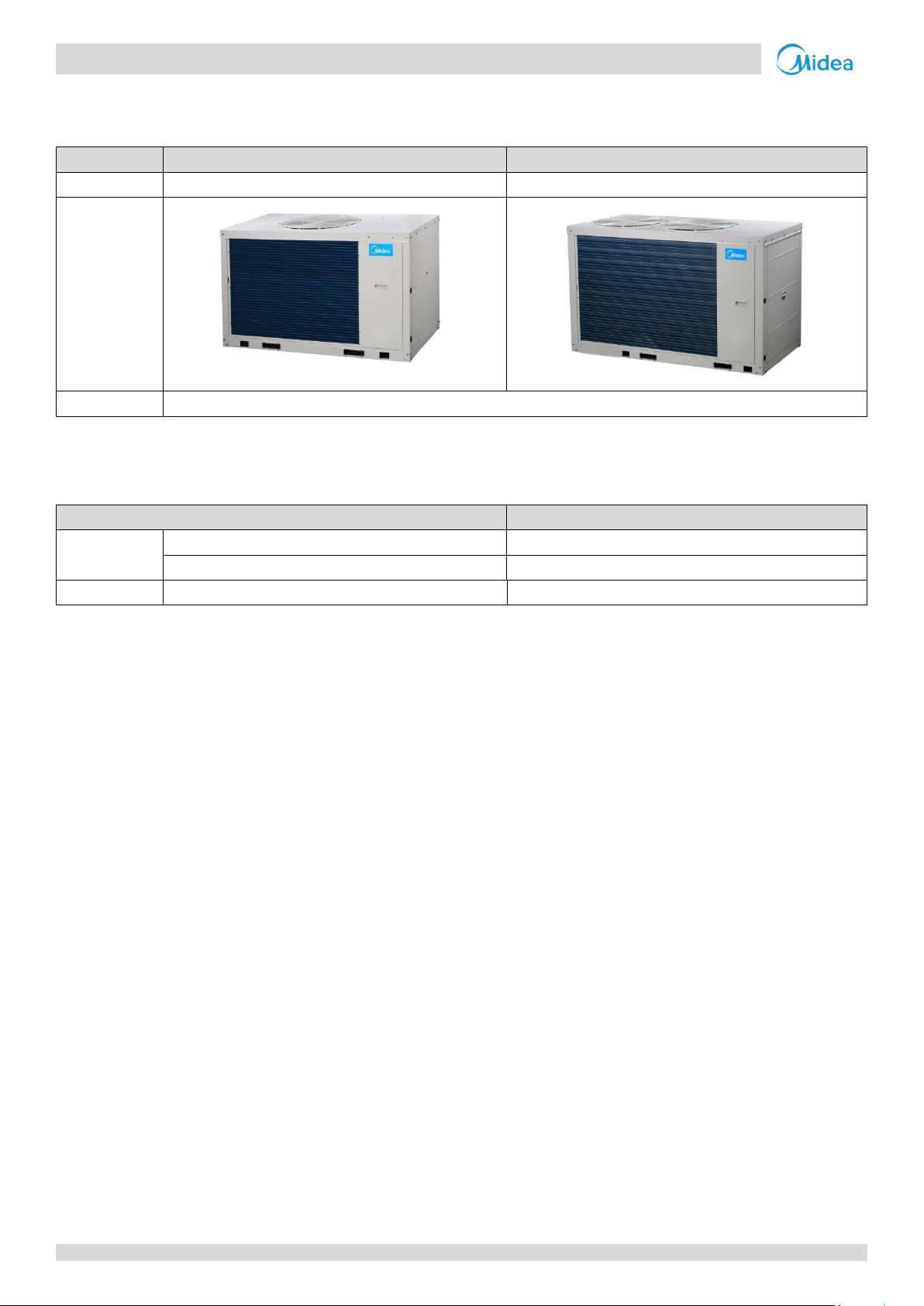
Table 1-2.1: Aqua Tempo Super II unit capacity range and unit appearances
Capacity
30kW
60kW
Model
MC-SU30-RN1L
MC-SU30-RN1L
Appearance
Power supply
380-415V/3Ph/50Hz
Table 1-2.1: Aqua Tempo Super II unit water outlet temperature range
Mode
Range
Cooling
Normal
5-20°C
Low water outlet
0-20°C
Heating
Normal
25-55°C
Note:
1. Use dial switch S5_1 on the main PCB to select the water outlet temperature range.
1 Unit Capacities and External Appearance
2 Water outlet temperature range
4 201709
Page 6

Aqua Tempo Super II
Refrigerant Ci rcuits
Part 2
Component Layout and
Refrigerant Circuits
1 Layout of Functional Components ........................................................... 6
2 Piping Diagrams ..................................................................................... 10
3 Refrigerant Flow Diagrams ..................................................................... 13
Part 2 - Component Layout and
201709 5
Page 7
Aqua Tempo Super II
Midea
Aqua Tempo S uper II
Service Manual
Safety
valve
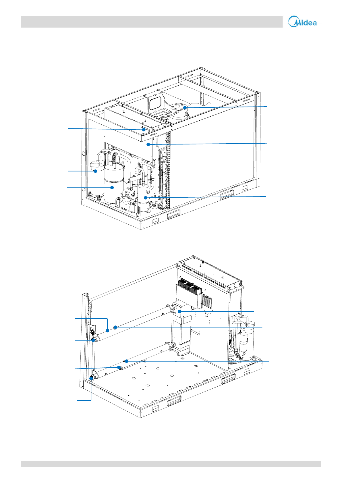
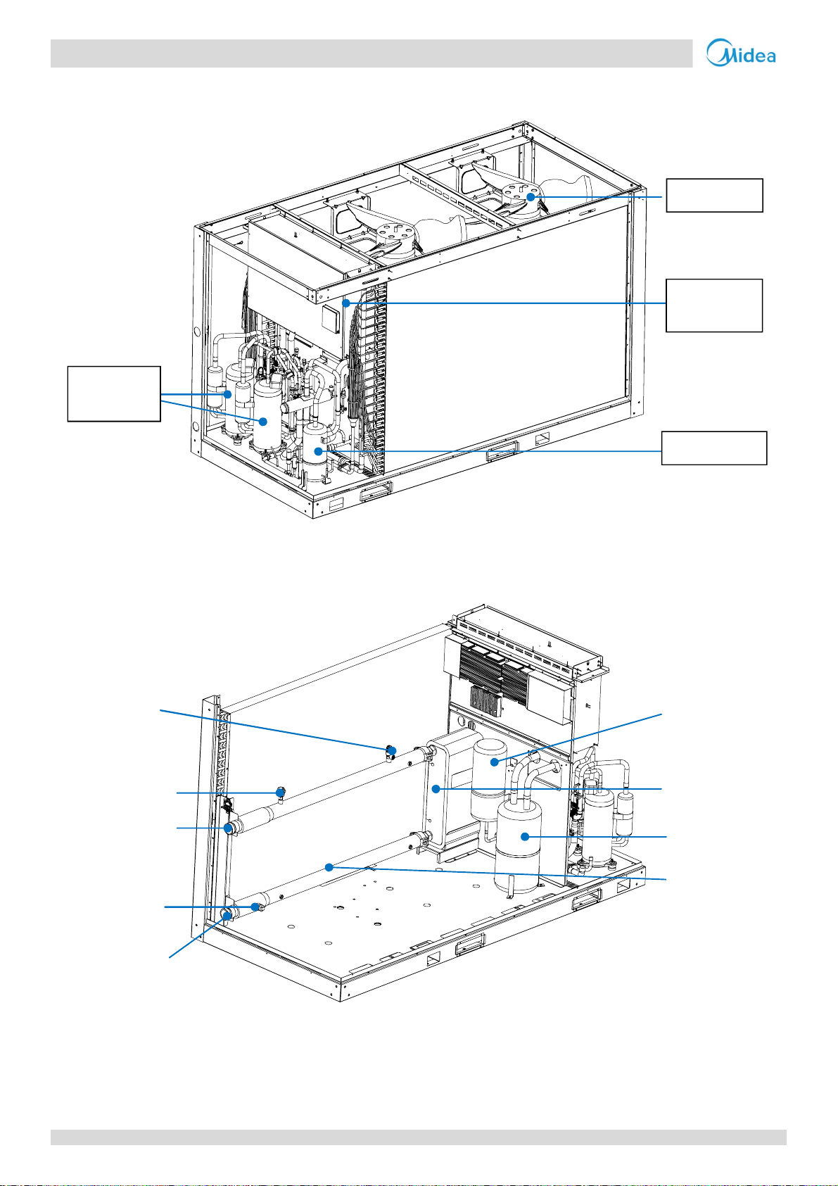
1 Layout of Functional Components
MC-SU30-RN1L
Figure 2-1.1: MC-SU30-RN1L front view
Wired
controller
DC inverter
compressor
Fan motor
Electric
control box
Accumulator
Figure 2-1.2: MC-SU30-RN1L rear view
Manual air
purge valve
Water inlet pipe
Oil separator
Water side heat exchanger
Manual water
drain valve
Water outlet
pipe
6 201612
Water flow switch
Page 8
Refrigerant Ci rcuits
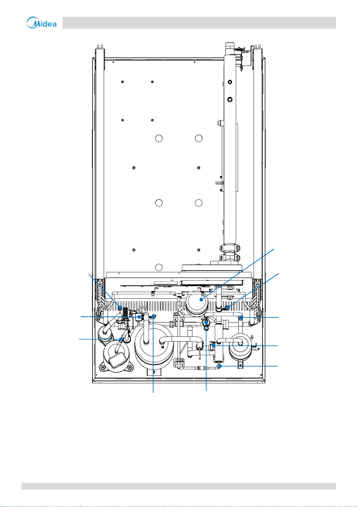
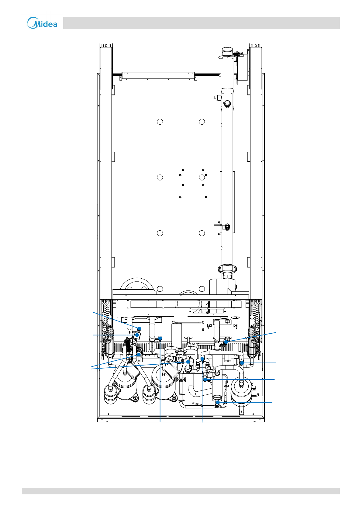
Figure 2-1.3: MC-SU30-RN1L top view
expansion valve
Aqua Tempo Super II
Part 2 - Component Layout and
Low pressure
switch
Solenoid valve
SV4
Discharge
temperature
switch
Low pressure
gauge point
Accumulator
High pressure
sensor
High pressure
switch
Four-way valve
Electronic
High pressure
gauge point
201709 7
Page 9
Aqua Tempo Super II
Midea
Aqua Tempo S uper II
Service Manual
control box
MC-SU60-RN1L
Figure 2-1.4: MC-SU60-RN1L front view
DC inverter
compressor
Fan motor
Electric
Oil separator
Figure 2-1.5: MC-SU60-RN1L rear view
Safety valve
Air purge valve
Water inlet pipe
Manual water
drain valve
Water outlet
pipe
Accumulator
Water side
heat exchanger
Accumulator
Water flow
switch
8 201612
Page 10
Refrigerant Ci rcuits
Figure 2-1.6: MC-SU60-RN1L top view
expansion valve
Aqua Tempo Super II
Part 2 - Component Layout and
Low pressure
switch
High pressure
Solenoid
valve SV4
Discharge
temperature
switch
Low pressure
gauge point
High pressure
gauge point
sensor
High pressure
switch
Four-way valve
Electronic
201709 9
Page 11
Aqua Tempo Super II
Midea
Aqua Tempo S uper II
Service Manual
6
2 Piping Diagrams
MC-SU30-RN1L
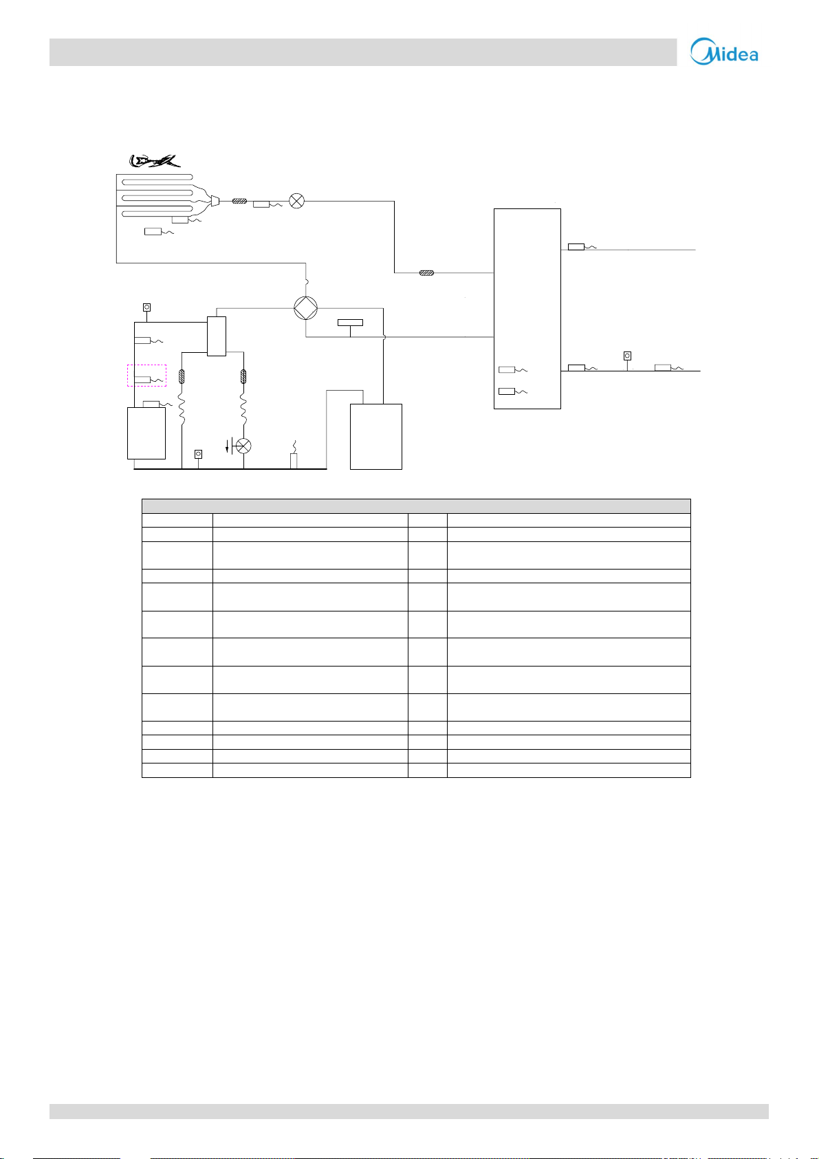
Figure 2- 2.1: MC-SU30-RN1L pipi ng diagram
Tz/7
T3
T4
EXV
11
Twi
4
ST1
9
7
3
TP2
TP1
1
Legend
10 Water flow switch Tw Combined water outlet temperature sensor
11 Filter Th Air suction temperature sensor
EXV Electronic expansion valve SV4 Oil return solenoid valve
ST1 4-way valve
5
Taf2 Tw
Taf1
2
1 Compressor Tp1 Discharge temperature sensor 1
2 Low pressure switch Tp2 Discharge temperature sensor 2
3 Discharge temperature control switch T3 Air side heat exchanger refrigerant outlet
4 High pressu re switch T4 Outdoor ambient temperature sensor
5 Oil separator TZ/7 Air side heat exchanger refrigerant total outlet
6 Air side heat excha nger Taf1 Water side heat exchanger anti-freezing
7 Pressure sensor Taf2 Water side heat exchanger anti-freezing
8 Accumulator Twi Water side heat exchanger water inlet temperature
9 Water side heat exchanger Two Water side heat exchanger water outlet
Th
SV4
8
temperature sensor
temperature sensor
temperature sensor 1
temperature sensor 2
sensor
temperature sensor
Two
10
10 201612
Page 12
Refrigerant Ci rcuits
MC-SU60-RN1L
6
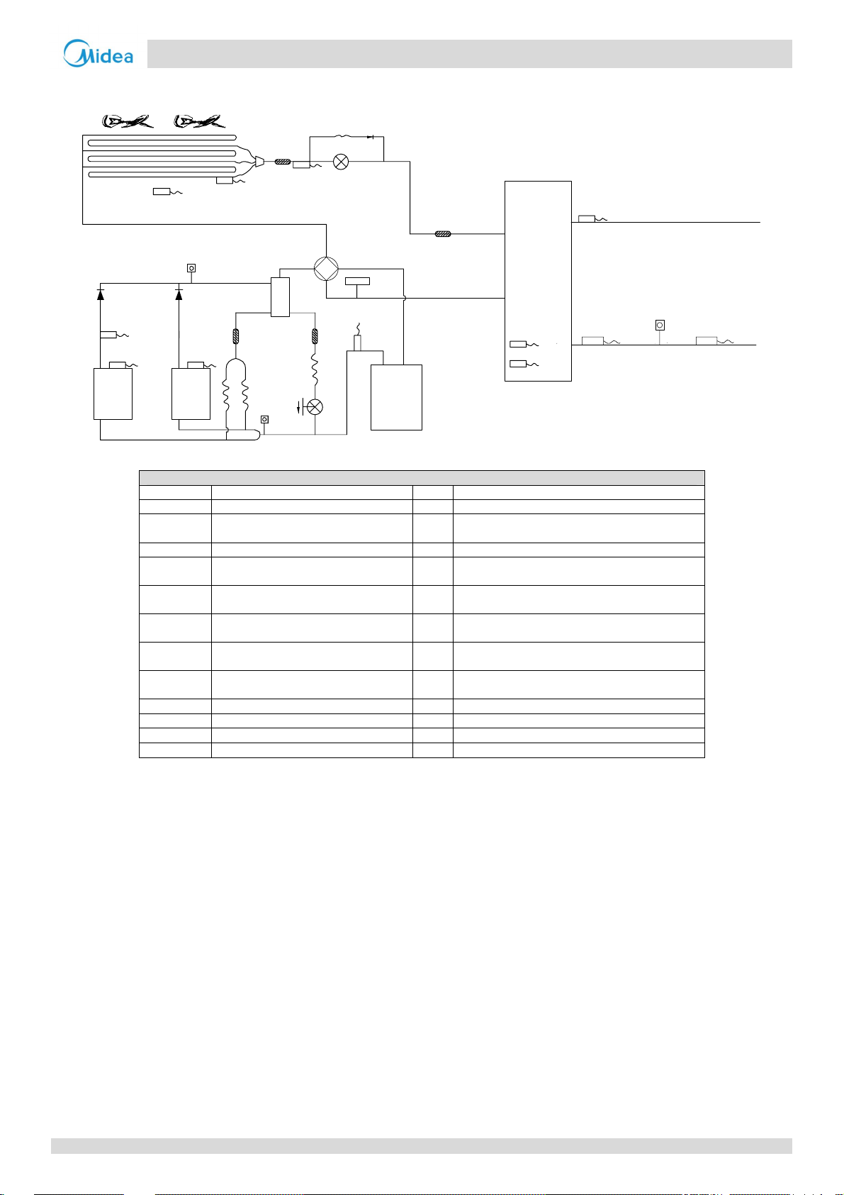
Figure 2- 2.2: MC-SU60-RN1L pipi ng diagram
T3
T4
Capillary
Tz
EXV
11
Aqua Tempo Super II
Twi
3
Tp1
1.1
4
ST1
Taf2
Taf1
9
Two
5
Tp2
1.2
SV4
Legend
1 Compressor Tp1 Discharge temperature sensor 1
2 Low pressure switch Tp2 Discharge temperature sensor 2
3 Discharge temperature control switch T3 Air side heat exchanger refrigerant outlet
4 High pressure switch T4 Outdoor ambient temperature sensor
5 Oil separator TZ/7 Air side heat exchanger refrigerant total outlet
6 Ai r side heat exchanger Taf1 Water side heat exchanger anti-freezing
7 Pressure sensor Taf2 Water side heat exchanger anti-freezing
8 Accumulator Twi Water side heat exchanger water inlet temperature
9 Water side heat exchanger Two Water side heat exchanger water outlet
10 Water flow switch Tw Combined water outlet temperature sensor
11 Filter Th Air suction temperature sensor
EXV Electronic expansion valve SV4 Oil return solenoid valve
ST1 4-way valve
7
Th
8
temperature sensor
temperature sensor
temperature sensor 1
temperature sensor 2
sensor
temperature sensor
10
Tw
Part 2 - Component Layout and
201709 11
Page 13

Aqua Tempo Super II
Midea
Aqua Tempo S uper II
Service Manual
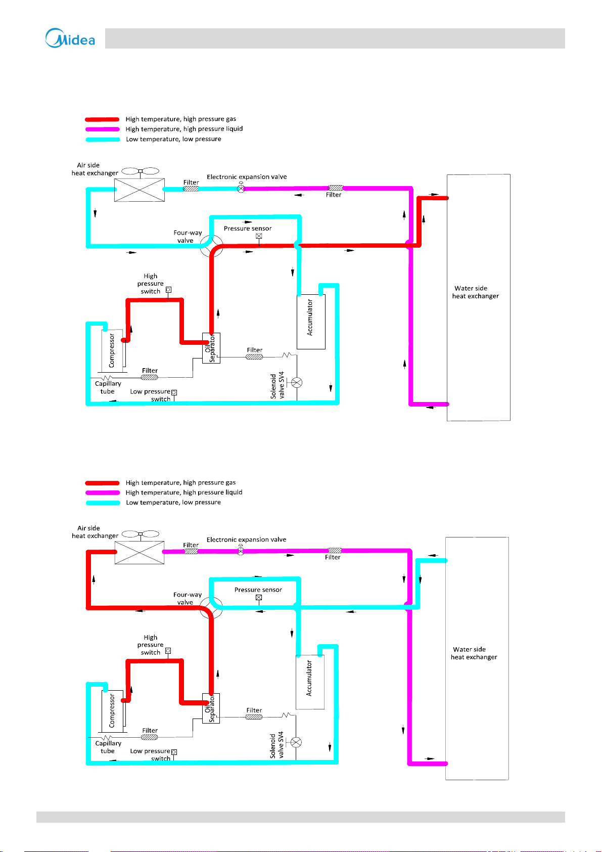
Key components:
1. Compressor
Maintains pressure differential between high and low pressure sides of the refrigerant system.
2. Fan
Ventilates the air side heat exchanger.
3. Oil separato r:
Separates oil from gas refrigerant pumped out of the compressor and quickly returns it to the compressor. Separation
efficiency is up to 99%.
4. Accumulator:
Stores liquid refrigerant and oil to protect the compressor from liquid hammering.
5. Electronic expansion valve (EXV):
Controls refrigerant flow and reduces refrigerant pressure.
6. Four-way valve:
Controls refrigerant flow direction. Closed in cooling mode and open in heating mode. When closed, the air side heat
exchanger functions as a condenser and water side heat exchanger functions as an evaporator; when open, the air
side heat exchanger functions as an evaporator and water side heat exchanger function as a condenser.
7. High and low pressure switches:
Regulate refrigerant system pressure. When the refrigerant system pressure rises above the upper limit or falls below
the lower limit, the high or low pressure switches turn off, stopping the compressor.
8. Discharge temperature switch:
Protects the compressor from abnormally high temperatures and transient spikes in temperature.
9. Air purge valve:
Automatically removes air from the water circuit.
10.Safety valve
Prevents excessive water pressure by opening at 43.5psi (3bar) and discharging water from the water circuit.
11.Water flow switch:
Detects water flow rate to protect the compressor and wat er pump in the event of insu fficient water flow.
12.Water pump:
Circulates water in the water circuit.
13.Pressure se n so r
Measures refrigerant system pressure.
14.Crankcase heater
Prevents refrigerant from mixing with compressor oil when the compressors are stopped.
15.Water side heat exchanger e lectric heater
Protects the water side heat exchanger from ice formation.
16.Water flow switch electric heater:
Provides additional heating when heating capacity provided by the heat pump is insufficient due to low ambient
temperatures, it also protects external water pipes from freezing.
17.Solenoid valve SV4
Returns oil to the compressor. It opens after 17 minut es of com pressor operation, closes after 3 minut es, t hen opens
again for 3 minutes at 17 minute increments.
12 201612
Page 14
Refrigerant Ci rcuits
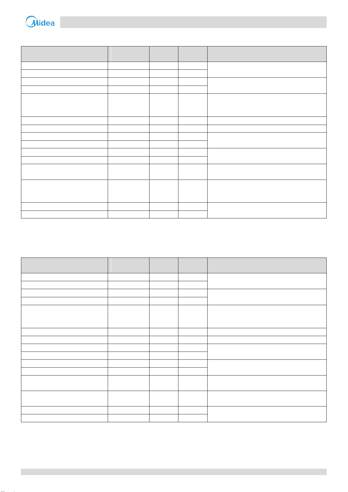
3 Refrigerant Flow Diagrams
Heating operation
Figure 2-3.1: Refrigerant flow during heating operation
Aqua Tempo Super II
Part 2 - Component Layout and
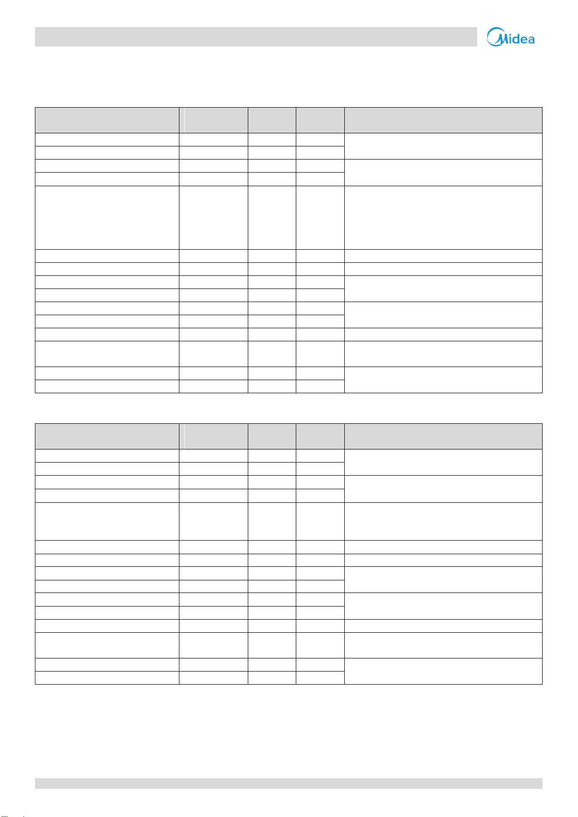
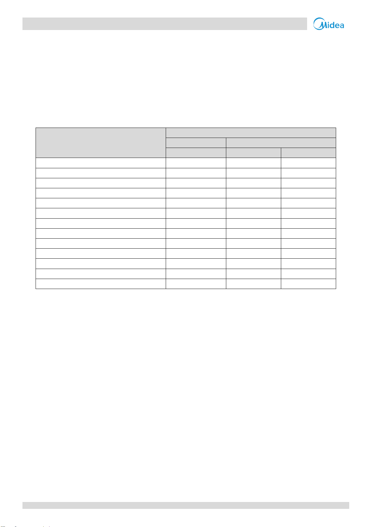
Cooling and defrosting operation
Figure 2-3.2: Refrigerant flow during cooling and defrosting o perations
201709 13
Page 15

Aqua Tempo Super II
Midea
Aqua Tempo S uper II
Service Manual
14 201612
Page 16

Aqua Tempo Super II
Part 3
- Control
Part 3
Control
1 General Control Scheme Flowchart ..................................................... 16
2 Stop Operation .................................................................................... 17
3 Standby Control .................................................................................. 17
4 Startup Control .................................................................................... 18
5 Normal Operation Control ................................................................... 20
6 Protection Control ............................................................................... 23
7 Special Control .................................................................................... 29
8 Role of Temperature Sensors in Control Functions ............................... 31
201709 15
Page 17
Aqua Tempo Super II
Midea Aqua Tempo Super II
Service Manual
S5_4 on main
PCB set to ON
Conditions met
for defrosting
Thermo on
Special control
Outdoor unit duty cycling
Additional control
Defrosting operation
7
Stop operation
System stops
2
Standby control
Water pump control
3
Startup control
Startup control for cooling operation
4
Thermo on
Normal operation control
Outdoor fan control
5
Protection control
Water side heat exchanger temperature difference protection control
6
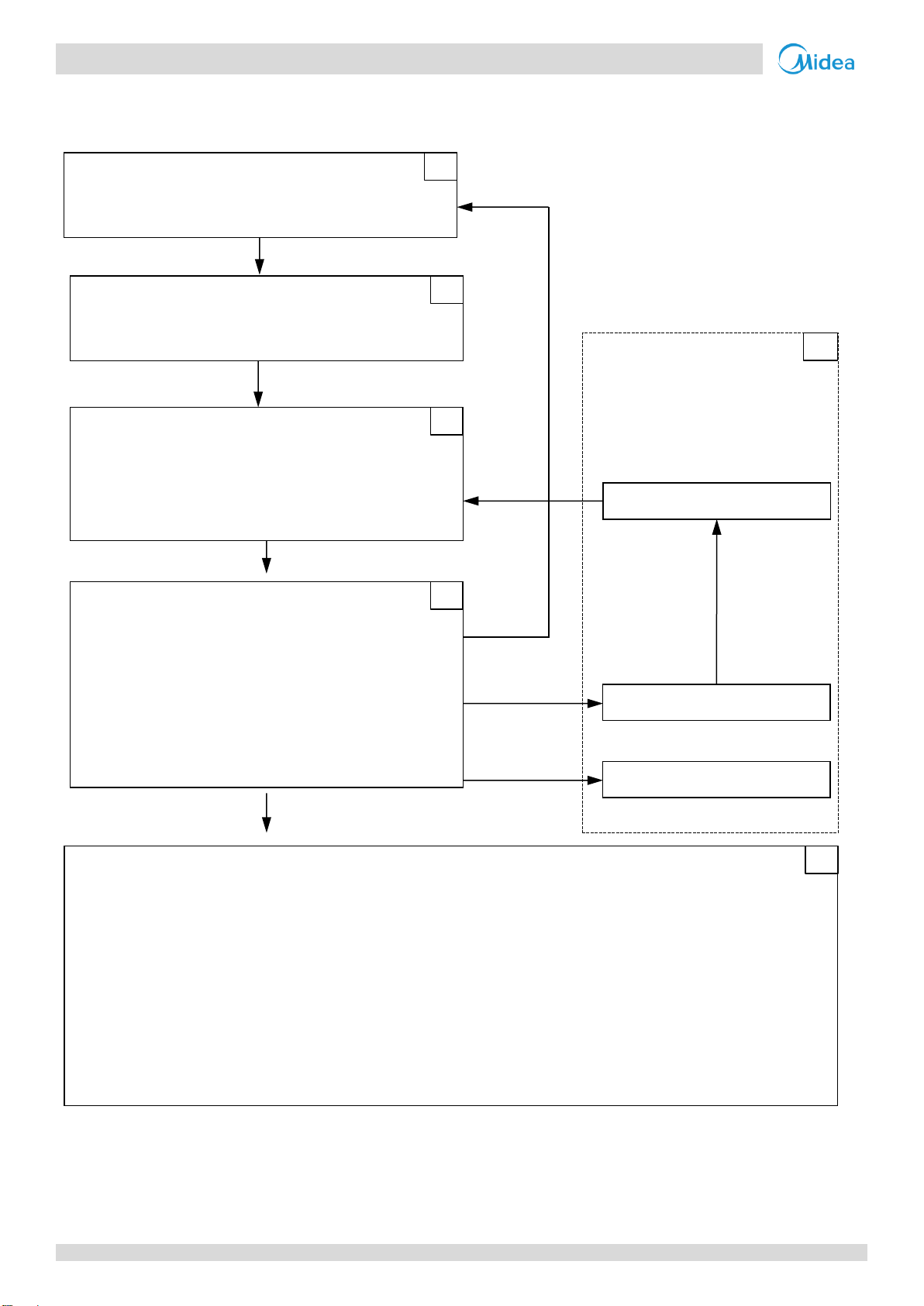
1 General Control Scheme Flowchart
Sections 3-2 to 3-7 on the following pages detail when each of the controls in the flowchart below is activated.
Abnormal shutdown
Crankcase heater control
Compressor startup delay control
Compressor startup program
Startup control for heating operation
Component control during normal operation
Compressor output control
Compressor step control
Water pump select control
Four-way valve control
Electronic expansion valve control
High pressure protection control
Low pressure protection control
Discharge temperature protection control
Compressor and inverter module protection control
Voltage protection control
DC fan motor protection control
Water side heat exchanger anti-freeze protection control
Air side heat exchanger high temperature protection control
Note:
1. Numbers in the top right-hand corners of boxes indicate the relevant section of text on the following pages.
16 201709
Page 18
Aqua Tempo Super II
Part 3
- Control
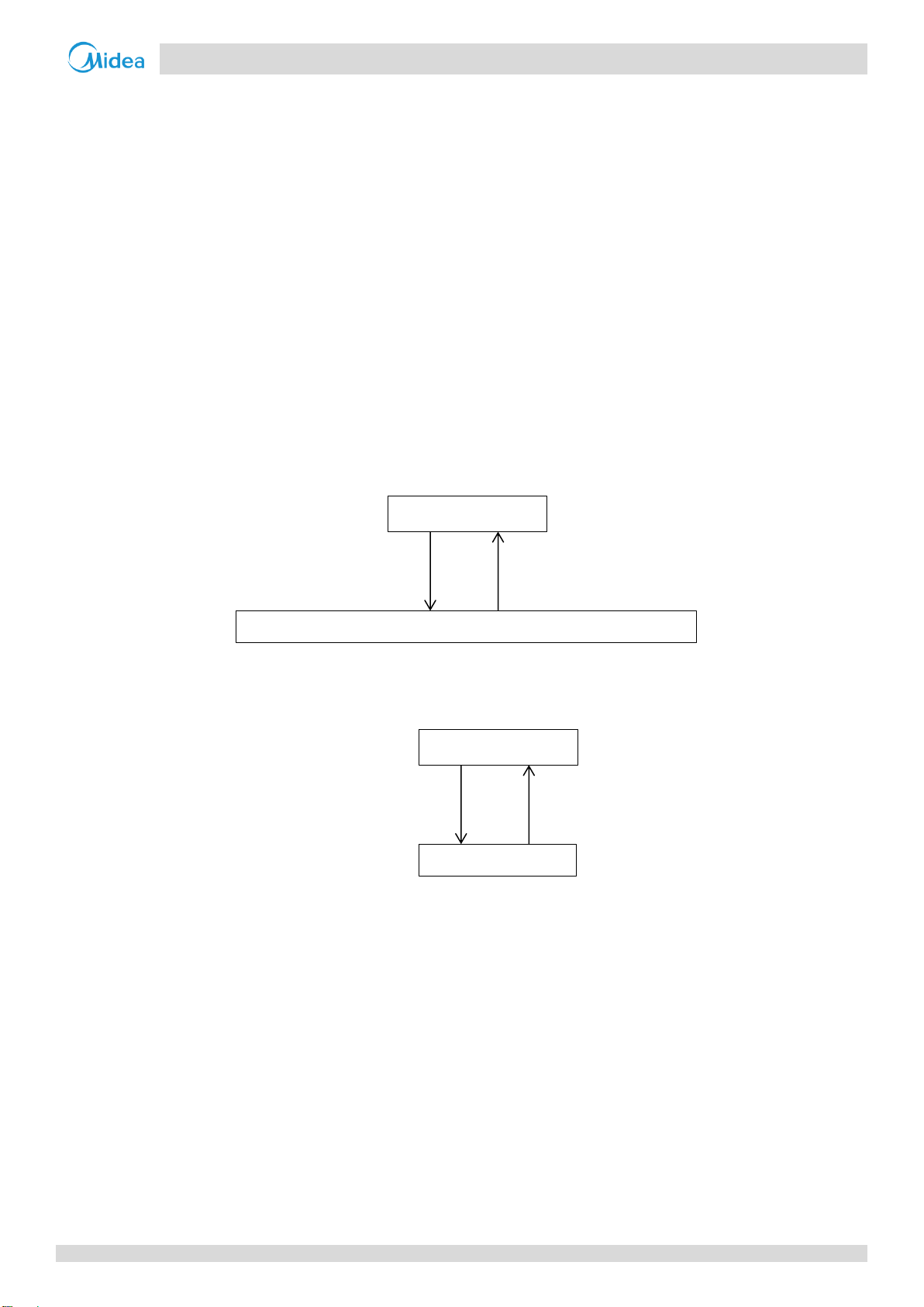
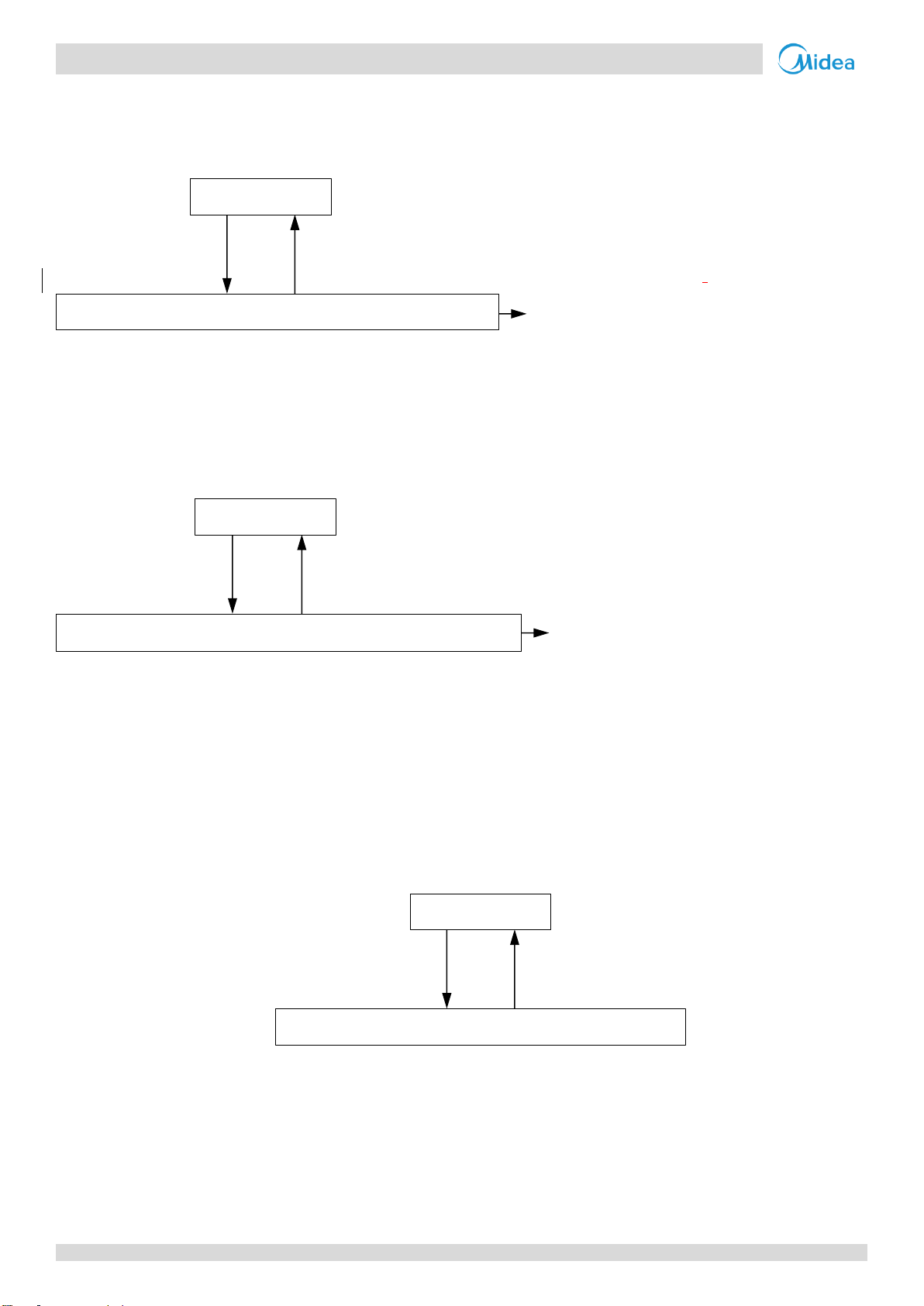
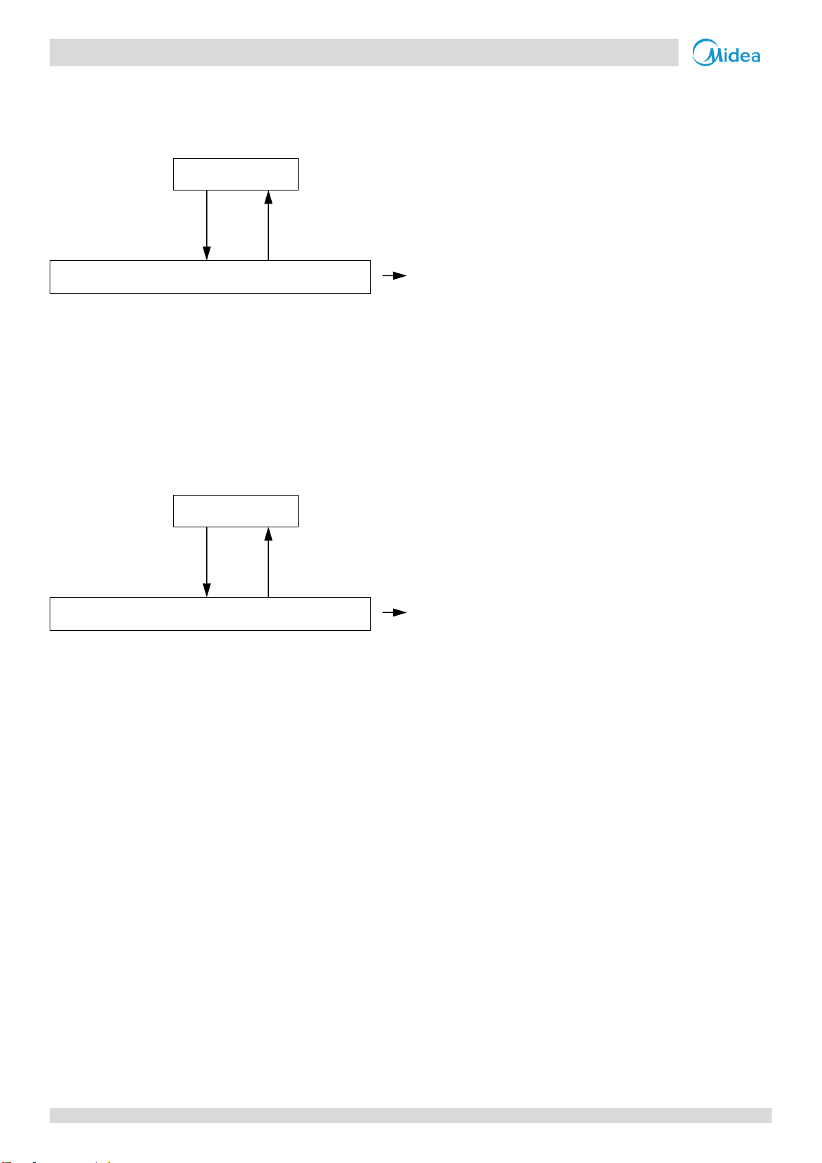
Figure 3-3.1: Crankcase heater controlled according to outdoor ambient temperature
Figure 3-3.2: Crankcase heater controlled according to discharge temperature
Notes:
1. Tp1: discharge temperature sensor 1, Tp2: discharge temperature sensor 2.
Ambient temperature < 35 oC
Ambient temperature > 40 oC
Crankcase heater off
Crankcase heater is controlled according to discharge temperature
Max (Tp1, Tp2) < 40 oC
Max (Tp1, Tp2) > 50 oC
Crankcase heater off
Crankcase heater on
2 Stop Operation
The stop operation occurs for one of the following reasons:
1. Abnormal shutdown: in order to protect the compressors, if an abnormal state occurs the system makes a 'stop with
thermo off’ operation and an error code is displayed on the outdoor unit’s PCB digital displays and on the user
interface.
2. The system stops when the set temperature has been reached.
3 Standby Control
3.1 Crankcase Heater Control
The crankcase heater is used to prevent refrigerant from mixing with compressor oil when the compressors are stopped.
The crankcase heater is controlled according to the outdoor ambient temperature and discharge temperature. When the
outdoor ambient temperature is above 40°C, the crankcase heater is off; when the outdoor ambient temperature is below
35°C, the crankcase heater is controlled according to discharge temperature. Refer to Figures 3-3.1 and 3-3.2.
3.2 Water Pump Control
When the outdoor unit is in standby, the circulator pumps run continuously。
201709 17
Page 19
Aqua Tempo Super II
Midea Aqua Tempo Super II
Service Manual
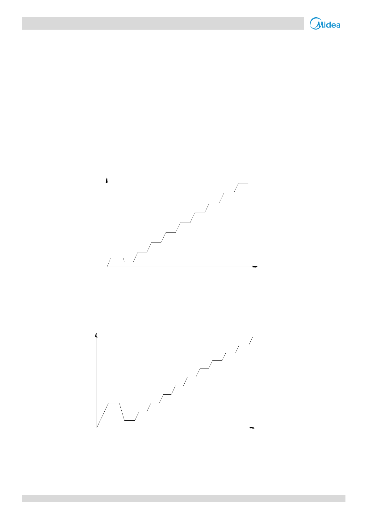
Figure 3-4.1: Compressor startup program1 when ambient temperature is above 10°C
Notes:
1. Once the first, 60-second stage of the program is complete, the program proceeds to the subsequent stages in a
step-by-step fashion and exits when the target rotation speed has been reached.
Figure 3-4.2: Compressor startup program1 when ambient temperature is at or below 10°C
Notes:
1. Once the first, 90-second stage of the program is complete, the program proceeds to the subsequent stages in a
step-by-step fashion and exits when the target rotation speed has been reached.
42rps
60S
56rps
34rps
66rps
76rps
80rps
90rps
90S
90S
90S
90S
180S
60S
180S
100rps
Target rotation speed
Compressor
rotation speed (rps)
Time (s)
105rps
300S
42rps
90S
28rps
120S
34rps
60S
42rps
90S
56rps
60S
76rps
60S
66rps
60S
80rps
90S
90rps
180S
100rps
180S
Target rotation speed
Compressor
rotation speed (rps)
Time (s)
105rps
300S
4 Startup Control
4.1 Compressor Startup Delay Control
In initial startup control and restart control (except in defrosting operation), compressor startup is delayed such that a
minimum 7 minutes has elapsed since the compressor stopped, in order to prevent frequency compressor on/off and to
equalize the pressure within the refrigerant system.
4.2 Compressor Startup Program
In initial startup control and in re-start control, compressor startup is controlled according to outdoor ambient
temperature and discharge temperature. Compressor startup follows one of two startup programs until the target rotation
speed is reached. Refer to Figures 3-4.1, 3-4.2.
18 201709
Page 20
Aqua Tempo Super II
Part 3
- Control
Component
Wiring diagram
label
30kW
60kW
Control functions and states
Inverter compressor A
COMP A
●
●
Compressor startup program selected according to
ambient temperature and discharge temperature1
Inverter compressor B
COMP B
●
DC fan motor A
FAN A
●
●
Controlled according to ambient temperature
DC fan motor B
FAN B
●
Electronic expansion valve
EXV 1
●
●
Position (steps) from 0 (fully closed) to 480 (fully
open), controlled according to outdoor ambient
temperature, unit capacity.
Four-way valve
STF1
●
●
On after the compressor startup for 10s
Solenoid valve (oil balance)
SV4_1
●
●
Closed for 200s, open for 600s, then closed
Water pump1
PUPM1
●
●
On
Water pump2
PUPM2
●
●
Water side heat exchanger heater 1
EVA-HEAT 1
●
●
According to water side heat exchanger
anti-freezing temperature (Taf)
Water side heat exchanger heater 2
EVA-HEAT 2
●
Water flow switch heater
W-HEAT1
●
●
Controlled according to ambient temperature, water
inlet temperature and water outlet temperature
Electric auxiliary heater
E-HEAT_L/
E-HEAT_N
●
●
Controlled according to ambient temperature and
total water outlet temperature after the compressor
is on
Crank case heater 1
HEAT1
●
●
Controlled according to ambient temperature and
discharge temperature
Crank case heater 2
HEAT2
●
Notes:
1. Refer to Figure 3-4.1, Figure 3-4.2 and in Part 3, 4.2 “Compressor Startup Program”.
Component
Wiring diagram
label
30kW
60kW
Control functions and states
Inverter compressor A
COMP A
●
●
Compressor startup program selected according to
ambient temperature and discharge temperature1
Inverter compressor B
COMP B
●
DC fan motor A
FAN A
●
Controlled according to air side heat exchanger
refrigerant total outlet temperature (Tz/7)
DC fan motor B
FAN B
●
Electronic expansion valve
EXV 1
●
●
Position (steps) from 0 (fully closed) to 480 (fully
open), controlled according to outdoor ambient
temperature, outdoor unit initial frequency
Four-way valve
STF1
●
●
Off
Solenoid valve (oil balance)
SV4_1
●
●
Closed for 200s, open for 600s, then closed
Water pump1
PUPM1
●
●
On
Water pump2
PUPM2
Water side heat exchanger heater 1
EVA-HEAT 1
●
●
According to water side heat exchanger
anti-freezing temperature (Taf)
Water side heat exchanger heater 2
EVA-HEAT 2
●
Water flow switch heater
W-HEAT1
●
●
Controlled according to ambient temperature, water
inlet temperature and water outlet temperature
Electric auxiliary heat
E-HEAT_L/
E-HEAT_N
●
●
Off
Crank case heater 1
Heat 1
●
●
Controlled according to ambient temperature and
discharge temperature
Crank case heater 2
Heat 2
●
Notes:
1. Refer to Figure 3-4.1, Figure 3-4.2 and in Part 3, 4.2 “Compressor Startup Program”.
4.3 Startup Control for Heating Operation
Table 3-4.1: Component control during startup in heating mode
4.4 Startup Control for Cooling Operation
Table 3-4.2: Component control during startup in cooling mode
201709 19
Page 21
Aqua Tempo Super II
Midea Aqua Tempo Super II
Service Manual
Component
Wiring diagram
label
30kW
60kW
Control functions and states
Inverter compressor A
COMP A
●
●
Controlled according to load requirement
Inverter compressor B
COMP B
●
DC fan motor A
FAN A
●
●
Controlled according to air side heat exchanger pipe
temperature and discharge pressure
DC fan motor B
FAN B
●
Electronic expansion valve
EXV 1
●
●
Position (steps) from 0 (fully closed) to 480 (fully
open), controlled according to discharge superheat
and compressor frequency, and use suction
temperature, air side heater exchanger temperature,
discharge temperature to modify the control.
Four-way valve
STF1
●
●
On
Solenoid valve (oil balance)
SV4_1
●
●
Open regularly
Water pump1
PUPM1
●
●
On
Water pump2
PUPM2
●
●
Water side heat exchanger heater 1
EVA-HEAT 1
●
●
Off
Water side heat exchanger heater 2
EVA-HEAT 1
●
Water flow switch heater
W-HEAT1
●
●
Off
Electric auxiliary heater
E-HEAT_L/
E-HEAT_N
●
●
Controlled according to ambient temperature
Crank case heater 1
HEAT1
●
●
Off
Crank case heater 2
HEAT2
●
Component
Wiring diagram
label
30kW
60kW
Control functions and states
Inverter compressor A
COMP A
●
●
Controlled according to load requirement
Inverter compressor B
COMP B
●
DC fan motor A
FAN A
●
●
Controlled according to air side heat exchanger
refrigerant total outlet temperature (Tz/7)
DC fan motor B
FAN B
●
Electronic expansion valve
EXV 1
●
●
Position (steps) from 0 (fully closed) to 480 (fully
open), controlled according to suction superheat,
water inlet temperature and compressor frequency.
Four-way valve
STF1
●
●
Off
Solenoid valve (oil balance)
SV4_1
●
●
Open regularly
Water pump1
PUPM1
●
●
On
Water pump2
PUPM2
●
●
Water side heat exchanger heater 1
EVA-HEAT 1
●
●
According to water side heat exchanger
anti-freezing temperature (Taf)
Water side heat exchanger heater 2
EVA-HEAT 2
●
Water flow switch heater
W-HEAT1
●
●
Off
Electric auxiliary heater
E-HEAT_L/
E-HEAT_N
●
●
Off
Crank case heater 1
HEAT1
●
●
Off
Crank case heater 2
HEAT2
●
5 Normal Operation Control
5.1 Component Control during Normal Operation
Table 3-5.1: Component control during heating operation
Table 3-5.2: Component control during cooling operation
20 201709
Page 22

Aqua Tempo Super II
Part 3
- Control
5.2 Compressor Output Control
The compressor rotation speed is controlled according to the load requirement. Before compressor startup, the outdoor
unit determines the compressor target speed according to outdoor ambient temperature, discharge temperature and then
runs the appropriate compressor startup program. Refer to Part 3, 4.2 “Compressor Startup Program”. Once the startup
program is complete, the compressor runs at the target rotation speed.
The compressor speed is controlled according to two parts in normal operation:
In cooling mode: In a single system, the compressor speed is controlled according to the water outlet temperature and
water outlet setting temperature. In a combination system, the compressor of master unit is controlled according total
water outlet temperature and water outlet setting temperature, the compressor of the slave unit is controlled according to
water inlet and water outlet temperature. Both in a single system and combination system, the compressor speed is
limited by the inverter module temperature (Tf), ambient temperature, discharge temperature and air side heat exchanger
refrigerant total outlet temperature (Tz/7).
In heating mode: In a single system, the compressor speed is controlled according to the water outlet temperature and
water outlet setting temperature. In a combination system, all compressors are controlled according to the total water
outlet temperature and the water outlet setting temperature. Both in a single system and combination system, the
compressor speed is limited by inverter module temperature (Tf), ambient temperature, discharge temperature, discharge
pressure.
5.3 Compressor Step Control
The running speed of six-pole compressors in rotations per second (rps) is one third of the frequency (in Hz) of the
electrical input to the compressor motor. The frequency of the electrical input to the compressor motors can be altered at
a rate of 1Hz in two seconds.
5.4 Water pump select control
When the dial switch S5_3 on the main PCB is switched ON, the system runs “one small pump per unit” mode, when S5_3
is switched OFF, the system run “one large pump controlled by master unit” mode.
One pump control: only the master unit output pump signal, no pump signal output on the slave units.
Multiple pump control: output pump signal on all units.
S5_3 in one system must be switched to the same position or not error code FP will be displayed.
5.5 Four-way Valve Control
The four-way valve is used to change the direction of refrigerant flow through the water side heat exchanger in order to
switch between cooling and heating operations. Refer to Figures 2-3.1 and 2-3.2 in Part 2, 3 “Refrigerant Flow Diagrams”.
During heating operation, the four-way valve is on; during cooling and defrosting operation, the four-way valve is off.
5.6 Electronic Expansion Valve Control
The position of the electronic expansion valve (EXV) is controlled in steps from 0 (fully closed) to 480 (fully open).
At power-on:
The EXV first closes fully, then moves to the standby position (352 (steps)). After 30seconds the EXV moves to an
initial running position, which is determined according to the operating mode and outdoor ambient temperature.
When the unit operate in cooling mode, after 60 seconds, the EXV is controlled according to suction superheat, water
inlet temperature and compressor frequency.
When the unit operates in heating mode, after a further 60 seconds, the EXV is controlled according to discharge
201709 21
Page 23
Aqua Tempo Super II
Midea Aqua Tempo Super II
Service Manual
Table 3-5.3: Outdoor fan speed steps
Fan speed index
Fan speed (rpm)
30kW
60kW
FAN A
FAN A
FAN B 0 0 0 0 1 150
150
0 2 200
200
0 3 250
250
0 4 300
300
250 5 360
360
300 6 430
430
360 7 480
530
460
8 (super silent mode)
530
650
580 9 650
760
680
10(silent mode)
710
850
800
11
800
900
850
12(standard ESP mode)
820
950
900
Abbreviations:
ESP: External static pressure
superheat and compressor frequency, and uses the suction temperature, air side heater exchanger temperature,
discharge temperature to modify the control.
When the outdoor unit is in standby:
The EXV is at position 352 (steps).
When the outdoor unit stops:
The EXV first closes fully, then moves to the standby position (352 (steps)).
5.7 Outdoor Fan Control
The speed of the outdoor unit fan(s) is adjusted in steps, as shown in Table 3-5.3.
22 201709
Page 24
Aqua Tempo Super II
Part 3
- Control
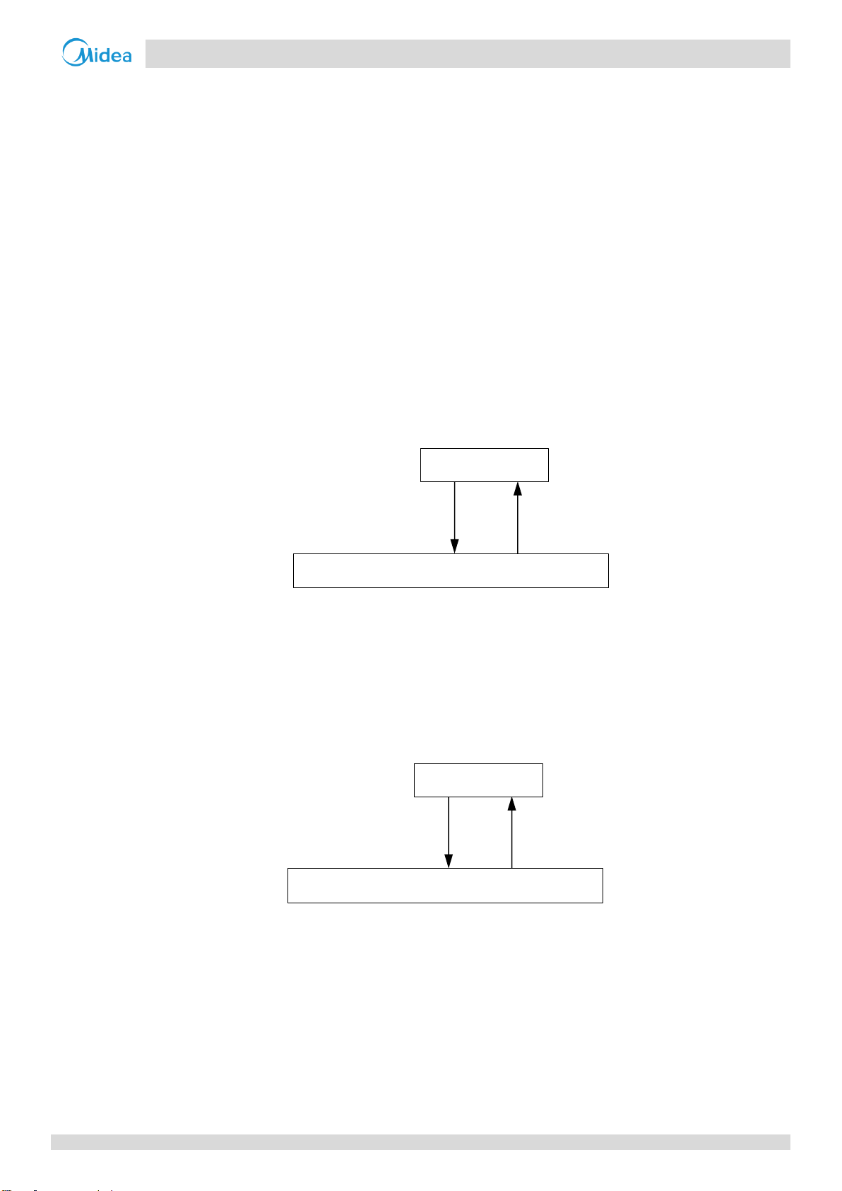
Figure 3-6.1: High pressure protection control
Notes:
1. P
c
: Discharge pressure
Figure 3-6.2: Low pressure protection control
Notes:
1. P
e
: Suction pressure
Figure 3-6.3: High discharge temperature protection control
When P1 protection occurs 5 times
in 120 minutes, ta manual system
restart is required before the system
can resume operation.
Pc > 4.4MPa
Pc < 3.2MPa
Normal operation
Low pressure protection, error code P0 is displayed
When P0 protection occurs 5 times
in 120 minutes, a manual system
restart is required before the system
can resume operation.
Pe < 0.14MPa
Pe > 0.3MPa
Normal operation
Low pressure protection, error code P1 is displayed
Discharge temperature > 110°C
Discharge temperature < 100°C
Normal operation
High discharge temperature protection, error code P0 is
When P0 protection occurs 5 times
in 120 minutes, ta manual system
restart is required before the system
can resume operation.
6 Protection Control
6.1 High Pressure Protection Control
This control protects the refrigerant system from abnormally high pressure and protects the compressor from transient
spikes in pressure.
When the discharge pressure rises above 4.4MPa the system displays P0 protection and all units stop running. When the
discharge pressure drops below 3.2MPa, the compressor enters re-start control.
6.2 Low Pressure Protection Control
This control protects the refrigerant system from abnormally low pressure and protects the compressor from transient
drops in pressure.
When the suction pressure drops below 0.14MPa the system displays P0 protection and all the units stop running. When
the suction pressure rises above 0.3MPa, the compressor enters re-start control.
6.3 Discharge Temperature Protection Control
This control protects the compressor from abnormally high temperatures and transient spikes in temperature.
When the discharge temperature rises above 110°C the system displays P0 protection and all the units stop running. When
the discharge temperature drops below 100°C , the compressor enters re-start control.
201709 23
Page 25
Aqua Tempo Super II
Midea Aqua Tempo Super II
Service Manual
Figure 3-6.4: Compressor current protection control
Notes:
1. P4 is the protection for the power supply phase B, P5 is the protection for the power supply phase C.
Figure 3-6.5: Inverter module temperature protection control
Notes:
1. Tf1:Heat sink temperature 1; Tf2:Heat sink temperature 2
Figure 3-6.6: Compressor voltage protection control
Current > 25A
Current < 25A
Normal operation
Compressor current protection, error code P4 or P5 is displayed
Tf1 or Tf2 > 82°C
Tf1 and Tf2 < 60°C
Normal operation
Inverter module temperature protection, error code PL is displayed
Voltage ≥ 260V
or Voltage < 165V
180V ≤ Voltage < 250V
Normal operation
Compressor voltage protection, error code H1 is displayed
When P4 or P5 protection occurs 5
times in 120 minutes, ta manual
system restart is required before the
system can resume operation.
C7 is displayed when PL error occurs
3 times in 100 minutes, a manual
system restart is required before the
system can resume operation.
6.4 Compressor and Inverter Module Protection Control
This control protects the compressors from abnormally high currents and protects the inverter modules from abnormally
high temperatures. It is performed for each compressor and inverter module.
When the compressor current rises above25A, the system displays P4 or P5 protection and all the units stop running.
When the compressor current drops below 25A, the compressor enters re-start control.
When the Tf1 or Tf2 temperature rises above 82°C , the system displays PL protection and all the units stop running. When
the Tf1 and Tf2 temperature drops below 60°C, the compressor enters re-start control.
6.5 Voltage Protection Control
This control protects the units from abnormally high or abnormally low voltages.
When the phase voltage of AC power supply is at or above 260V for more than 30 seconds, the system displays H1
protection and all the units stop running. When the phase voltage drops below 250V for more than 30 seconds, the units
restart once the compressor re-start delay has elapsed. When the phase voltage is below 165V for more than 30 seconds,
the system displays H1 protection and all the units stop running. When the AC voltage rises to at or above 180V for more
than 30 seconds, the refrigerant system restarts once the compressor re-start delay has elapsed.
24 201709
Page 26
Aqua Tempo Super II
Part 3
- Control
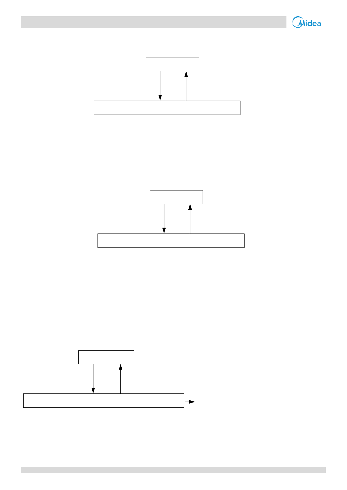
Figure 3-6.7: Anti-freeze protection control in normal cooling mode
Note:
1. Taf include Taf1 and Taf2.
Figure 3-6.8: Anti-freeze protection control in low water outlet cooling mode
Note:
1. Taf include Taf1 and Taf2.
Min(Tw/Two/Twi/Taf1) ≤ 4°C
Tw > 15°C
Normal operation
Anti-freeze protection, error code Pb is displayed
Min(Tw/Two/Twi/Taf1) ≤ 0°C
Tw > 15°C
Normal operation
Anti-freeze protection, error code Pb is displayed
6.6 DC Fan Motor Protection Control
This control protects the DC fan motors from abnormal power supply. DC fan motor protection occurs when the fan
module does not receive any feedback from the fan motor.
When DC fan motor protection control occurs the system displays the PU error code and the unit stops running. When PU
protection occurs 2 times in 120 minutes, the FF error is displayed. When an FF error occurs, a manual system restart is
required before the system can resume operation.
6.7 Water Side Heat Exchanger Anti-freeze Protection Control
This control protects the water side heat exchanger from ice formation. The water side heat exchanger electric heater is
controlled according to water side heat exchanger anti-freezing temperature (Taf), water inlet temperature (Twi), water
outlet temperature (Two) and total water outlet temperature (Tw).
When water side heat exchanger anti-freeze protection occurs the system displays error code Pb and all the units stop
running.
In standby or normal cooling mode, either water side heat exchanger anti-freezing temperature (Taf), water inlet
temperature (Twi), water outlet temperature (Two) or total water outlet temperature (Tw) is below 4°C, the unit will run
heating mode , until the total water outlet temperature is above 15°C, and restart the normal operation.
In low water outlet cooling mode, either water side heat exchanger anti-freezing temperature (Taf), water inlet
temperature (Twi), water outlet temperature (Two) or total water outlet temperature (Tw) is below 0°C, the unit will run
heating mode , until the total water outlet temperature is above 15°C, and restart the normal operation.
201709 25
Page 27
Aqua Tempo Super II
Midea Aqua Tempo Super II
Service Manual
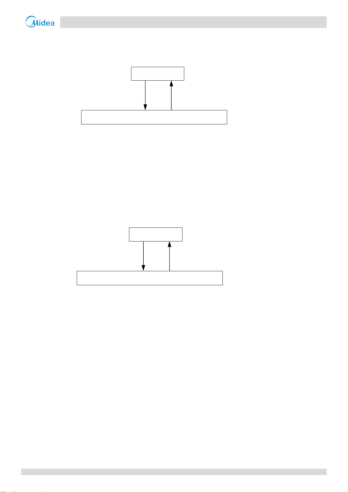
Figure 3-6.9: Air side heat exchanger high temperature protection control 1
Note:
1. T3: Air side heat exchanger refrigerant outlet temperature
Figure 3-6.10: Air side heat exchanger temperature protection control 2
Note:
1. Tz/7: Air side heat exchanger refrigerant total outlet temperature
Figure 3-6.11: Water side heat exchanger temperature difference protection control
Notes:
1. Twi: Water side heat exchanger inlet temperature
2. Two: Water side heat exchanger outlet temperature
T3 > 65°C
T3 < 60°C
Normal operation
High temperature protection, error code P7 is displayed
Tz/7 ≥ 62°C
Tz/7 < 62°C
Normal operation
High temperature protection, error code P7 is displayed
∣Twi-Two∣≥ 12°C
∣Twi-Two∣< 6°C
Normal operation
Temperature difference protection, error code P9 is displayed
When P9 protection occurs 3 times
in 60 minutes, a manual system
restart is required before the system
can resume operation.
6.8 Air Side Heat Exchanger High Temperature Protection Control
This control protects the air side heat exchanger from high temperature.
When the air side heat exchanger refrigerant outlet temperature (T3) rises above 65°C , the system displays P7 protection
and all the units stop running. When the air side heat exchanger refrigerant outlet temperature (T3) drops below 60°C, the
compressor enters re-start control.
When the air side heat exchanger refrigerant total outlet temperature (Tz/7) temperature rises at or above 62°C , the
system displays P7 protection and the unit stops running. When the air side heat exchanger refrigerant total outlet
temperature (Tz/7) temperature drops below 62°C, the compressor enters re-start control.
6.9 Water Side Heat Exchanger Temperature Difference Protection Control
This control protects the water side heat exchanger from ice formation.
When the temperature difference rises at or above 12°C , the system displays P9 protection and all the units stop running.
When the Temperature difference drops below 6°C, the compressor enters re-start control.
26 201709
Page 28
Aqua Tempo Super II
Part 3
- Control
Figure 3-6.12: Water side heat exchanger low temperature protection control in normal cooling mode
Notes:
1. Taf1: Water side heat exchanger anti-freezing temperature1
2. Taf2: Water side heat exchanger anti-freezing temperature2
Figure 3-6.13: Water side heat exchanger low temperature protection control in low water outlet mode
Min (Taf1 or Taf2) ≤ 3°C
Min (Taf1 and Taf2) >10°C
Normal operation
Low temperature protection, error code PE is
Min (Taf1 or Taf2) ≤ 0°C
Min (Taf1 and Taf2) > 5°C
Normal operation
Low temperature protection, error code PE is displayed
6.10 Water Side Heat Exchanger Low Temperature Protection Control
This control protects the water side heat exchanger from ice formation.
When water side heat exchanger anti-freezing temperature1 (Taf1) or water side heat exchanger anti-freezing
temperature2 (Taf2) is at or below 3°C for more than 3 seconds, the system displays PE protection and the corresponding
unit stop running. When water side heat exchanger anti-freezing temperature1 (Taf1) and Water side heat exchanger
anti-freezing temperature2 (Taf2) rise to 10°C or higher, the compressor enters re-start control. Use the user interface to
clear the error.
When water side heat exchanger anti-freezing temperature1 (Taf1) or water side heat exchanger anti-freezing
temperature2 (Taf2) is at or below 0°C for more than 3 seconds, the system displays PE protection and orders the
corresponding units to stop running. When water side heat exchanger anti-freezing temperature1 (Taf1) and Water side
heat exchanger anti-freezing temperature2 (Taf2) rise to 5°C or higher, the compressor enters re-start control. Use the user
interface to clear the error.
201709 27
Page 29
Aqua Tempo Super II
Midea Aqua Tempo Super II
Service Manual
Figure 3-6.14: Water side heat exchanger low pressure protection control in normal cooling mode
Note:
1. Pe: Suction pressure
Figure 3-6.15: Water side heat exchanger low pressure protection control in low water outlet cooling mode
Note:
1. Pe: Suction pressure
Pe < 0.6Mpa
Pe ˃ 0.6Mpa
Normal operation
Low pressure protection, error code PC is
Pe < 0.4Mpa
Pe ˃ 0.4Mpa
Normal operation
Low pressure protection, error code PC is
When system displays PC protection
and a manual system restart is
required before the system can
resume operation.
When system displays PC protection
and a manual system restart is
required before the system can
resume operation.
6.11 Water Side Heat Exchanger Low Pressure Protection Control
This control protects the water side heat exchanger from ice formation.
In normal cooling mode, when the suction pressure drops below 0.6Mpa, the system displays PE protection and all the
units stop running. When the suction pressure is above 0.6Mpa or higher, the compressor enters re-start control. It will not
display the PC error when the suction pressure drops below 0.6Mpa for the first time until the suction pressure drops
below 0.6Mpa for the second time in 30 minutes.
In low water outlet cooling mode, when the suction pressure drops below 0.4Mpa, the system displays PE protection and
all the units stop running. When the suction pressure is above 0.4Mpa or higher, the compressor enters re-start control. It
will not display the PC error when the suction pressure drops below 0.4Mpa for the first time until the suction pressure
drops below 0.4Mpa for the second time in 30 minutes.
28 201709
Page 30
Aqua Tempo Super II
Part 3
- Control
Startup control
Normal operation
After defrosting operation or on
restart following compressor stop
after set temperature s reached
Normal operation
Outdoor unit
duty cycling
Priority
1
Priority
2
……
Priority
16
Master
Slave 1
Slave 15
Outdoor unit
duty cycling
Priority
16
Priority
15
Priority
1
Master
Slave 1
Slave 15
……
7 Special Control
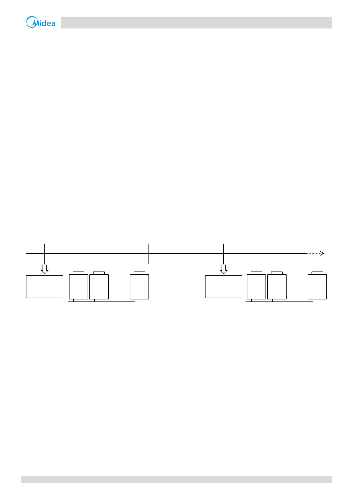
7.1 Outdoor Unit Duty Cycling
In systems with multiple outdoor units, outdoor unit duty cycling is used to balance the compressor running time.
Outdoor unit duty cycling occurs whenever all the outdoor units stop running (either because the leaving water set
temperature has been reached or because a master unit error has occurred):
When the outdoor units are powered on for the first time, if there is a load requirement, the units turn on, starting
with the master unit. As the leaving water temperature approaches its set temperature, units shut down in succession,
starting with the unit with the highest address. Once the set temperature has been reached, the master unit shuts
down.
The next time a load requirement exists (or, following a master unit error), the units turn on, starting with the unit
with the highest address. As the leaving water temperature approaches its set temperature, units shut down in
succession, starting with the unit with the lowest address (the master unit). Once the set temperature has been
reached, the unit with the highest address shuts down.
Figure 3-7.1 shows an example of duty cycling in a system with 16 outdoor units.
Figure 3-7.1: Duty cycling in a system with 16 outdoor units
1
Notes:
1. The address settings on the outdoor unit main PCBs for master unit and slave unit do not change.
7.2 Defrosting Operation
In order to recover heating capacity, the defrosting operation is conducted when the outdoor unit air side heat exchanger
is performing as a condenser. The defrosting operation is controlled according to outdoor ambient temperature, air side
heat exchanger refrigerant outlet temperature and the compressor running time.
The defrosting operation ceases when any one of the following three conditions occurs:
Defrosting operation duration reaches 10 minutes.
The air side heat exchanger refrigerant outlet temperature reaches the target temperature.
The water outlet temperature is at or below 5°C .
201709 29
Page 31

Aqua Tempo Super II
Midea Aqua Tempo Super II
Service Manual
Component
Wiring diagram
label
30kW
60kW
Control functions and states
Inverter compressor A
COMP A
●
●
Runs at defrosting operation rotation speed
Inverter compressor B
COMP B
●
DC fan motor A
FAN A
●
●
Off
DC fan motor B
FAN B
●
Electronic expansion valve
EXV 1
●
●
Full open
Four-way valve
STF1
●
●
Off
Solenoid valve (oil balance)
SV4_1
●
●
Open regularly
Water pump1
PUPM1
●
●
ON
Water pump2
PUPM2
●
●
Water side heat exchanger heater 1
EVA-HEAT 1
●
●
Off
Water side heat exchanger heater 2
EVA-HEAT 2
●
Water flow switch heater
W-HEAT1
●
●
Off
Electric auxiliary heat
E-HEAT_L
●
●
According to ambient temperature
Crank case heater 1
HEAT1
●
●
Off
Crank case heater 2
HEAT2
●
Table 3-7.1: Component control during defrosting operation
7.3 Additional control
When dial switch S5_4 on main PCB is switched ON, additional control is valid, connect a controller or not is permissible.
When dial switch S5_4 is switched OFF, additional control is invalid. This function is only valid on the master unit.
When dial switch S5_4 is switched ON and disconnect a wired controller:
The system ON/OFF state is controlled by the ON/OFF port (CN44 on the main PCB). Connecting this port, system on,
disconnecting this port, system off.
The mode of the system is controlled by the Cool/Heat port (CN44 on the main PCB). Connecting this port, system
running heating mode, disconnecting this port, system running cooling mode.
The default water outlet temperature setting in heating mode is 45°C and in cooling mode is 7°C . The default
hysteresis temperature setting is 2°C .
The network icon on the wired controlled flashes, frequency and “rctc” alternate display on main PCB .
When dial switch S5_4 is switched ON and connect a wired controller, the water outlet temperature and hysteresis
temperature can be set by the wired controller.
30 201709
Page 32

Aqua Tempo Super II
Part 3
- Control
Number
Sensor name1
Sensor
code
Mode
Control functions
1
Discharge pipe temperature sensor 1/ Discharge pipe
temperature sensor 2
Tp1/Tp2
Heating
Crankcase heater control
1
Electronic expansion valve control
2
Compressor output control
3
Discharge temperature protection
control4
Cooling
Crankcase heater control
1
Compressor output control
3
Discharge temperature protection
control4
2
Outdoor ambient temperature sensor
T4
Heating
Crankcase heater control
1
Electric auxiliary heater control
Water flow switch heater control
Compressor output control
3
Electronic expansion valve control
2
Outdoor fan control
5
Cooling
Crankcase heater control
1
Compressor output control
3
Defrosting operation control
6
Electronic expansion valve control
2
Outdoor fan control
5
3
Air side heat exchanger refrigerant outlet temperature
sensor
T3
Heating
Outdoor fan control
5
Electronic expansion valve control
2
Cooling
Defrosting operation control
6
Air side heat exchanger high
temperature protection control7
4
Total cooling outlet temperature sensor
TZ/7
Heating
None
Cooling
Outdoor fan control
5
Compressor output control
3
Air side heat exchanger high
temperature protection control7
5
Water side heat exchanger anti-freezing temperature
sensor1/Water side heat exchanger anti-freezing
temperature sensor 2
Taf1/
Taf2
Heating
None
Cooling
Water side heat exchanger heater
control
Water side heat exchanger anti-freeze
protection control8
Water side heat exchanger low
temperature protection control9
6
Suction pipe temperature sensor
Th
Heating
Electronic expansion valve control
2
Cooling
Electronic expansion valve control
2
7
Water inlet temperature sensor
Twi
Heating
Water flow switch heater control
Cooling
Electronic expansion valve control
2
Compressor output control
3
Water flow switch heater control
Water side heat exchanger anti-freeze
protection control8
Water side heat exchanger
temperature difference protection
control10
8
Water outlet temperature sensor
Two
Heating
Compressor output control
3
Water flow switch heater control
Cooling
Compressor output control
3
Defrosting operation control
6
Water flow switch heater control
Water side heat exchanger anti-freeze
protection control8
Water side heat exchanger
temperature difference protection
control10
8 Role of Temperature Sensors in Control Functions
Table 3-8.1: Names and functions of the temperature sensors
201709 31
Page 33

Aqua Tempo Super II
Midea Aqua Tempo Super II
Service Manual
9
Total water outlet temperature sensor
Tw
Heating
Compressor output control
3
Electric auxiliary heater control
Cooling
Compressor output control
3
Water side heat exchanger anti-freeze
protection control8
10
Inverter module temperature sensor 1/ Inverter module
temperature sensor 2
Tf1/Tf2
Heating
Compressor output control
3
Inverter module temperature
protection11
Cooling
Compressor output control
3
Outdoor fan control
5
Inverter module temperature
protection11
Notes:
1. Refer to part 3, 3.1 “Crankcase Heater Control".
2. Refer to part 3, 5.6 “Electronic Expansion Valve Control".
3. Refer to part 3, 5.2 “Compressor Output Control".
4. Refer to part 3, 6.3 “Discharge Temperature Protection Control".
5. Refer to part 3, 5.7 “Outdoor Fan Control".
6. Refer to part 3, 7.2 “Defrosting Operation".
7. Refer to part 3, 6.8 “Air Side Heat Exchanger High Temperature Protection Control".
8. Refer to part 3, 6.7 “Water Side Heat Exchanger Anti-freeze Protection Control ".
9. Refer to part 3, 6.10 “Water Side Heat Exchanger Low Temperature Protection Control ".
10. Refer to part 3, 6.9 “Water Side Heat Exchanger Temperature Difference Protection Control ".
11. Refer to part 3, 6.4 “Compressor and Inverter Module Protection Control "
12. All sensor names in his service manual referring to refrigerant flow is named according refrigerant flow during cooling operation refer to
part2,3 ”Refrigerant Flow Diagram ”.
32 201709
Page 34

Aqua Tempo Super II
Part
4 - Diagnosis and Troubleshooting
Part 4
Diagnosis and
Troubleshooting
1 Outdoor Unit Electric Control Box Layout ............................................. 34
2 Outdoor Unit PCBs ............................................................................... 36
3 Error Code Table .................................................................................. 47
4 Troubleshooting .................................................................................. 49
5 Appendix to Part 5 ............................................................................... 95
201709 33
Page 35

Aqua Tempo Super II
Midea Aqua Tempo Super II
Service Manual
Figure 4-1.1: Electric control box front view- top layer
Main control board
Wired controller
Power supply terminal
3-way terminal
Figure 4-1.2: Electric control box front view-bottom layer
AC indicator A
AC filter board
Reactor
Inverter module
AC indicator B
Fan module
Three-phase bridge rectifier
1 Outdoor Unit Electric Control Box Layout
MC-SU30-RN1L
34 201709
Page 36

Aqua Tempo Super II
Part
4 - Diagnosis and Troubleshooting
Figure 4-1.3: Electric control box front view-top layer
AC filter board A
Main control board
Wired controller
3-way terminal
Figure 4-1.4: Electric control box side view-bottom layer
Inverter module A
Three-phase bridge
rectifier B
Inverter module B
Reactor A
AC indicator A
Three-phase
bridge
rectifier A
Reactor B
Power supply
terminal
Fan module B
AC filter board B
AC indicator B
Fan module A
MC-SU60-RN1L
201709 35
Page 37

Aqua Tempo Super II
Midea Aqua Tempo Super II
Service Manual
Figure 4-2.1: Outdoor unit main PCB
1 2 3 4 5 6 7 8 9
36
35
34
33
32
31
30
10
11
12
13
14
15
16
29 28 27 26 25 24 23 22 21 20 19 18 17
30
2 Outdoor Unit PCBs
2.1 Types
Aqua Tempo Super II units have four PCBs – main control board, three phase AC filter board, DC fan inverter module board
and compressor inverter module board.
In addition to the four PCBs, MC-SU30-RN1L model each has one board while MC-SU30-RN1L model have one main control
board and the other boards each has two boards.
The locations of each PCB in the outdoor unit electric control boxes are shown in Figures 4-1.1 to 4-1.4 in Part 4, 1
“Outdoor Unit Electric Control Box Layout”.
2.2 Main PCB
Note:
1. Label descriptions are given in Table 4-2.1
36 201709
Page 38

Aqua Tempo Super II
Part
4 - Diagnosis and Troubleshooting
Table 4-2.1:Outdoor unit main PCB
Label in
Figure
4-2.1
Code
Content
Voltage
1
CN1
Pump 1 connection
0-220V AC(varying)
2
CN30
Power sequence detection connection
380V 3 S5
DIP switches
- 4 CN72
Power supply to user interface
9V DC 5 ENC1
Unit capacity dial switch
- 6 ENC3
Address dial switch
- 7 DSP1
Digital display
- 8 FUS1
Fuse
220V AC
9
CN43
Power input
220V AC
10
CN12_1,
CN12_2
Solenoid valve(SV4) drive ports
0-220V AC(varying)
11
IC25
Main control chip
-
12
CN64
Debug port
5V DC
13
CN16
Four-way valve drive port
0-220V AC(varying)
14
CN5,
CN5_1
Water side heat exchanger heater connections
0-220V AC(varying)
15
CN4,
CN4_1
Water flow switch heater connection
0-220V AC(varying)
16
CN3
CN3_1
Compressor crankcase heater connections
0-220V AC(varying)
17
CN49
Reserved communication port
2.5-2.7V DC
18
CN52
CN53
Fan inverter module communication ports
2.5-2.7V DC
19
CN50
CN51
Compressor inverter module communication ports
2.5-2.7V DC
20
CN55
EXV drive port
12V DC
21
CN60
CN71
Wired controller communication ports
2.5-2.7 DC
22
CN24
Outdoor ambient temperature sensor and air side heat exchanger refrigerant
outlet temperature sensor connections
0-5V DC (varying)
23
CN69
Water side heat exchanger anti-freezing temperature sensor 1, air side heat
exchanger refrigerant total outlet temperature sensor, discharge temperature
sensor 2 and discharge temperature sensor 1 connections
0-5V DC (varying)
24
CN31
Air suction temperature sensor, water side heat exchanger anti-freezing
temperature sensor 2, water side heat exchanger water outlet temperature
sensor, water side heat exchanger water inlet temperature sensor and combined
water outlet temperature sensor connections
0-5V DC (varying)
25
CN40
Pressure sensor connection
0-5V DC (varying)
26
CN41
CN42
Inverter module temperature sensor 1 and Inverter module temperature sensor 2
connections
0-5V DC (varying)
27
CN62
AC indicator A and AC indicator B connections
0-5V DC (varying)
28
CN65
Low pressure switch connection
0 or 5V DC (varying)
29
CN47
High pressure switch and discharge temperature switch (es) connections
0 or 5V DC (varying)
30
CN58
CN59
AC filter board communication ports
12V DC
201709 37
Page 39

Aqua Tempo Super II
Midea Aqua Tempo Super II
Service Manual
31
CN44
Water flow switch, additional control and Cool/heat connections
0 or 12V DC
32
IC10
EEPROM - 33
CN21
Remote alarm connection
On/off signal
34
CN19_N
Electric auxiliary heater N line connection
On/off signal
35
CN19_L
Electric auxiliary heater N line connection
On/off signal
36
CN2
Pump 2 connection
On/off signal
Table 4-2.2: Main PCB switch settings
Switch
Description
ON
OFF
Default factory
setting
S5
S5-1
Water outlet temperature1
Low
Normal
OFF
S5-2
ON/OFF function
Activated
Deactivated
OFF
S5-3
Water pump
One large pump
controlled by
master unit
One small
pump per
unit
OFF
S5-4
Reserved
- - OFF
ENC2
ENC2
0: MC-SU30-RN1L
- - 0
3: MC-SU60-RN1L
- - 3
ENC1
ENC1
0: master unit
1,2,3…F: slave units
-
-
0
-
-
Table 4-2.3: Function of buttons SW1 to SW4
Button
Function
SW3
Up
SW4
Down
SW5
Menu
SW5
Ok
Table 4-2.4: SW4 system check
Number
Parameters displayed on digital display
Remarks
0
Operating status
Standby: ODU address (DSP1 display) + number
of on-line units (DSP2 display)
On: display frequency
Defrosting: dF and operating frequency flash
alternately at 1s intervals frequency
OFF
ON
1 2 3 4
SW3
SW6
SW4
SW5
Main PCB field setting 2.2.1
Note:
1. Low water outlet temperature range: 0⁰C to 20⁰C; normal water outlet temperature range: 5⁰C to 20⁰C.
Function of buttons SW3 to SW6 2.2.2
SW2 system check button 2.2.3
Before pressing SW3 or SW4, allow the system to operate steadily for more than an hour. On pressing SW4, the parameters
listed in Table 4-2.4 will be displayed in sequence.
38 201709
Page 40

Aqua Tempo Super II
Part
4 - Diagnosis and Troubleshooting
Anti-freezing protection: Pb and operating
frequency flash alternately at 1s intervals
1
Outdoor unit address
Actual value = value displayed
2
Outdoor unit capacity
0:30KW; 3:60KW
3
Number of outdoor units (main unit display)
Actual value = value displayed
4
Unit capacity corrected for ambient temperature
Actual value = value displayed
5
Operating mode
8: Off; 0: Standby; 1: Cooling; 2: Heating
6
Fan A speed index
Refer to Note1
7
Fan B speed index
Refer to Note1
8
Air side heat exchanger refrigerant outlet temperature (sensor T3)
Actual value = value displayed
9
Outdoor ambient temperature (sensor T4)
Actual value = value displayed
10
Reserved
-
11
Water side heat exchanger anti-freezing temperature1 (sensor Taf1)
Actual value = value displayed
12
Water side heat exchanger anti-freezing temperature2 (sensor Taf2)
Actual value = value displayed
13
Total water outlet temperature(Tw)
Actual value = value displayed
14
Water inlet temperature(Twi, displays to decimal places)
Actual value = value displayed
15
Water outlet temperature(Two)
Actual value = value displayed
16
Air side heat exchanger refrigerant total outlet temperature (Tz/7)
Actual value = value displayed
17
Reserved
-
18
Compressor discharge temperature 1 (sensor Tp1)
Actual value = value displayed
19
Compressor discharge temperature 2 (sensor Tp2)
Actual value = value displayed
20
Compressor module temperature(Tf1)
Actual value = value displayed
21
Compressor module temperature(Tf2)
Actual value = value displayed
22
Air discharge superheat degree
Actual value = value displayed
23
Power supply phase B current
Actual value = value displayed
24
Power supply phase C current
Actual value = value displayed
25
Reserved
-
26
EXV 1 position
Steps=value displayed*4
27
Reserved
-
28
Compressor discharge pressure(in heating mode)
Actual value = value displayed
29
Compressor suction pressure (displays to decimal places in cooling mode)
Actual value = value displayed
30
Air suction superheat degree
Actual value = value displayed
31
Air suction temperature (Th)
Actual value = value displayed
32
Silent selection
Refer to Note2
33
Static pressure selection
0
34
Reserved
-
35
Reserved
-
36
Most recent error or protection code
“--”is displayed if no error or protection events
have occurred since start-up
37
Limit frequency number
0: no limits;
1: ambient temperature(T4) limit frequency;
2: voltage limit frequency;
3: air discharge limit frequency;
4: low voltage ratio;
5: instant limit frequency;
6: current limit frequency;
7: voltage limit frequency;
201709 39
Page 41

Aqua Tempo Super II
Midea Aqua Tempo Super II
Service Manual
8: pressure ratio and capacity demand
adjusting;
9: cooling low pressure limit frequency)
38
Defrosting process status
The first digit: T4 selection solution;
The second digit: scheme's range;
The third and fourth digits : defrosting time
39
EEPROM mismatch indicator:
1 : failure;
0 : no failure
40
Defrosting scheme
Actual value = value displayed
41
Initial frequency
Actual value = value displayed
42
Tc(+30)/Te(+25)
Actual value = value displayed
43
Online units statistic
Actual value = value displayed
44
Program version
Actual value = value displayed
45
---
-
Notes:
1. The fan speed index is related to the fan speed in rpm as described in Table 3-5.3 in Part 3, 5.6 “Outdoor Fan Control”.
2. Silent mode:
0: night silent mode; 1: silent mode; 2: super silent mode; 3: no silent mode.
40 201709
Page 42

Aqua Tempo Super II
Part
4 - Diagnosis and Troubleshooting
Table 4-2.5: Digital display output in different operating states
Outdoor unit state
Parameters displayed on DSP1
Parameters displayed on DSP2
Standby
0
1
Normal
operation
For single
compressor units
None
Running speed of compressor
For dual
compressor units
Running speed of compressor A in
rotations per second
Running speed of compressor B in
rotations per second
Error or protection
-- or placeholder
Error or protection code
System check
Refer to Table 4-2.4
Refer to Table 4-2.4
DSP1
DSP2
Digital display output 2.2.4
201709 41
Page 43

Aqua Tempo Super II
Midea Aqua Tempo Super II
Service Manual
Figure 4-2.2: Compressor inverter module PCB
1
17
16
15
14
2
3
4
5
6
13 12 11 10 9 8 7
Notes:
1. Label descriptions are given in Table 4-2.6.
2.3 Compressor Inverter Module Board
42 201709
Page 44

Aqua Tempo Super II
Part
4 - Diagnosis and Troubleshooting
Table 4-2.6: Compressor inverter module PCB
Label in
Figure
4-2.2
Code
Content
Voltage
1
SW1
Inverter module address switch
- 2 IC14
EEPROM
-
3
CN9
CN10
Inverter module communication port
2.5-2.7V DC
4
W
Compressor connections
V
UV
= V
Uw
= VVW
0-380V AC
5 V 6 U 7
N
IPM module input port N
VPN= 540V DC
8
P
IPM module input port P
9
N2
IPM module protection port N2
V
P2N2
= 540V DC
10
P2
IPM module protection port P2
11
CN15
Power supply inverter module board
310V DC
12
N1
IPM module power supply port N1
V
P1N1
=540V DC
13
P1
IPM module power supply port P1
14
CN3
Three-phase bridge rectifier positive port
540V DC relative
to N
15
CN11
Three-phase bridge rectifier control port
15V DC
16
CN1
Reactor port
540V DC relative
to N
17
CN4
Capacity positive port
540V DC relative
to N
Table 4-2.7: Compressor inverter module PCB switch settings
Switch
Description
SW1
000: MC-SU30-RN1L compressor inverter module address setting
000: MC-SU60-RN1L compressor A inverter module address setting
001: MC-SU60-RN1L compressor B inverter module address setting
OFF
ON
1 2 3
Compressor Inverter Module PCB field setting 2.3.1
201709 43
Page 45

Aqua Tempo Super II
Midea Aqua Tempo Super II
Service Manual
Figure 4-2.3: Fan module PCB
1 2
7
6
5 4 3
Table 4-2.8: Fan module PCB
Label in
Figure
4-2.3
Code
Content
Voltage
1
CN2
EEPROGRAM
-
2
CN1
CN4
Communication port for inverter module
2.5-2.7 DC
3
P
Power supply for inverter module
V
PN
= 310V DC
4
CN3
Power supply for the fan motor
V
UV
= V
Uw
= VVW
0-310V AC
5
N
Power supply for inverter module
V
PN
= 310V DC
6
U3
IPM - 7
SW1
Address for the inverter module
-
Table 4-2.9: Fan module PCB switch settings
Switch
Description
SW1
SW1-1
SW1-2
00: MC-SU30-RN1L fan module address setting
00: MC-SU60-RN1L fan module A address setting
01: MC-SU60-RN1L fan module B address setting
SW1-3
SW1-4
Reserved
OFF
ON
1 2 3 4
2.4 Fan Module Board
Fan Module PCB field setting 2.4.1
44 201709
Page 46

Aqua Tempo Super II
Part
4 - Diagnosis and Troubleshooting
Figure 4-2.4: AC filter board1
12
11
10
9
8
1
2
3
4
5
6
5
6
7
Notes:
1. Label descriptions are given in Table 4-2.10.
2.5 AC Filter Board
201709 45
Page 47

Aqua Tempo Super II
Midea Aqua Tempo Super II
Service Manual
Table 4-2.10: MHC-V10(12, 14, 16)W/D2N1 outdoor unit main PCB for
refrigerant system
Label in
Figure
4-2.4
Code
Content
Voltage
1
CN39
N1
V
L1N1=VL2N1=VL3N1
=220V
V
CN38
L1 3 CN37
L2 4 CN36
L3
5
CN1
CN2
Power supply for compressor inverter module
310V DC
6
CN3
CN4
Power supply for fan inverter module
310V DC
7
CN6
AC filter board communication port
12 DC
8
CN40
L3’
V
L1’N1’=VL2’N1’=VL3’N1’
=220V
9
CN41
L2’
10
CN42
L1’
11
CN43
N1’
12
GND
GND
-
46 201709
Page 48

Aqua Tempo Super II
Part
4 - Diagnosis and Troubleshooting
Error
code
Content
Remarks
1E0
Main PCB EEPROM mismatch
Displayed on main PCB and user interface
2E0
Inverter module A EEPROM mismatch
Displayed on main PCB and user interface
3E0
Inverter module B EEPROM mismatch
Displayed on main PCB and user interface
E1
Power phase sequence error
Displayed on main PCB and user interface
E2
Communication error between main PCB and wired
controller
Displayed on main PCB and user interface
E3
Total water outlet temperature sensor (Tw) error
(displayed on master unit only)
Displayed on main PCB and user interface
E4
Outlet water temperature sensor (Two) error
Displayed on main PCB and user interface
E5
Air-side heat exchanger temperature sensor (T3) error
Displayed on main PCB and user interface
E7
Outdoor ambient temperature sensor (T4) error
Displayed on main PCB and user interface
E9
Water flow failure
Displayed on main PCB and user interface
1Eb
Water-side heat exchanger anti-freezing temperature
sensor1 (Taf1) error
Displayed on main PCB and user interface
1Eb
Water-side heat exchanger anti-freezing temperature
sensor2 (Taf2) error
Displayed on main PCB and user interface
EC
Number of units detected by wired controller has
decreased
Displayed on main PCB and user interface
1Ed
Compressor discharge temperature sensor1 (Tp1) error
Displayed on main PCB and user interface
2Ed
Compressor discharge temperature sensor2 (Tp2) error
Displayed on main PCB and user interface
EF
Inlet water temperature sensor (Twi) error
Displayed on main PCB and user interface
EH
System self-check error
Displayed on main PCB and user interface
EP
Compressor discharge temperature sensor error
Displayed on main PCB and user interface
EU
Total cooling outlet temperature sensor (Tz/7) error
Displayed on main PCB and user interface
P0
Compressor discharge temperature protection
Displayed on main PCB and user interface
P1
Compressor suction temperature protection
Displayed on main PCB and user interface
P4
Power supply phase B Current protection
Displayed on main PCB and user interface
P5
Power supply phase C Current protection
Displayed on main PCB and user interface
1P6
System A inverter module protection
Displayed on main PCB and user interface
2P6
System A inverter module protection
Displayed on main PCB and user interface
P7
Condenser tube and Total cooling outlet high
temperature protection
Displayed on main PCB and user interface
P9
Water-side heat exchanger inlet/outlet temperature
difference protection
Displayed on main PCB and user interface
PA
Inlet water high temperature in cooling mode
Displayed on main PCB and user interface
Pb
System anti-freezing protection
Displayed on main PCB and user interface
PC
Evaporator pressure low in cooling mode
Displayed on main PCB and user interface
PE
Low-temperature protection of evaporator (manual
recovery)
Displayed on main PCB and user interface
PL
Module high temperature protection
Displayed on main PCB and user interface
1PU
DC fan 1 module protection
Displayed on main PCB and user interface
2PU
DC fan 2 module protection
Displayed on main PCB and user interface
3 Error Code Table
201709 47
Page 49

Aqua Tempo Super II
Midea Aqua Tempo Super II
Service Manual
1H0
System A IPM module Communication error
Displayed on main PCB and user interface
2H0
System B IPM module Communication error
Displayed on main PCB and user interface
H1
Under/Over voltage protection
Displayed on main PCB and user interface
1H6
System 1 DC bus voltage error
Displayed on main PCB and user interface
2H6
System 2 DC bus voltage error
Displayed on main PCB and user interface
Fb
Pressure sensor error
Displayed on main PCB and user interface
Fd
Air suction temperature(Th) protection error
Displayed on main PCB and user interface
1FF
DC fan 1 error
Displayed on main PCB and user interface
2FF
DC fan 2 error
Displayed on main PCB and user interface
FP
DIP inconsistency of multiple water pumps(Power
failure recovery required)
Displayed on main PCB and user interface
L0
Inverter module protection
-
L1
DC bus low voltage protection
-
L2
DC bus high voltage protection
-
L4
MCE error
-
L5
Zero speed protection
-
L7
Phase sequence error
-
L8
Compressor frequency variation greater than 15Hz
within one second protection
-
L9
Actual compressor frequency differs from target
frequency by more than 15Hz protection
-
dF
Defrosting indicator
Displayed on main PCB and user interface
48 201709
Page 50

Aqua Tempo Super II
Part
4 - Diagnosis and Troubleshooting
All electrical work must be carried out by competent and suitably qualified, certified and
accredited professionals and in accordance with all applicable legislation (all national, local and other laws,
Power-off the outdoor units before connecting or disconnecting any connections or wiring, otherwise electric
shock (which can cause physical injury or death) may occur or damage to components may occur.
Warning
4 Troubleshooting
4.1 Warning
standards, codes, rules, regulations and other legislation that apply in a given situation).
201709 49
Page 51

Aqua Tempo Super II
Midea Aqua Tempo Super II
Service Manual
E0
Main PCB or IPM inverter module
EEPROM1 is not connected properly
Yes
Ensure the EEPROM is connected
properly
No
EEPROM damaged
Yes
Replace the EEPROM
No
Replace refrigerant system Main PCB or
IPM inverter module
4.2 E0 Troubleshooting
Digital display output 4.2.1
Description 4.2.2
1E0 indicates main PCB EEPROM error.
2E0 indicates IPM inverter module (compressor A) EEPROM error.
3E0 indicates IPM inverter module (compressor B) EEPROM error.
All units stop running.
Error code is displayed on main PCB and user interface...d user interface.
Possible causes 4.2.3
Main PCB or IPM inverter module EEPROM is not connected properly.
Main PCB or IPM inverter module damaged.
EEPROM damaged.
Procedure 4.2.4
Notes:
1. Main PCB EEPROM is designated IC10 on the main PCBs (labeled 32 in Figure 4-2.1 in Part 4, 2.2 “Main PCB”).
2. Compressor inverter module PCB EEPROM is designated IC14 on compressor inverter module PCB (labeled 2 in Figure 4-2.2 in Part 4, 2.3 “Compressor
inverter module PCB”).
50 201709
Page 52

Aqua Tempo Super II
Part
4 - Diagnosis and Troubleshooting
4.3 E1 Troubleshooting
Digital display output 4.3.1
Description 4.3.2
Phase sequence error.
Unit stops running.
Error code is displayed on main PCB and user interface.
Possible causes 4.3.3
Power supply phases not connected in correct sequence.
Power supply terminals loose.
Power supply abnormal.
Main PCB damaged.
201709 51
Page 53

Aqua Tempo Super II
Midea Aqua Tempo Super II
Service Manual
E1
The phase sequence of the 3-phase
power supply is incrorrect1
Yes
Exchange any two of the 3 phase wires
No
Some power supply terminals are loose2
Yes
Ensure all supply terminals are securely
fastened
No
The power supply is abnormal
Yes
Check the power supply equipment
No
Replace refrigerant system main PCB
Procedure 4.3.4
Notes:
1. The A, B, C terminals of 3-phase power supply should match compressor phase sequence requirements. If the phase sequence is inverted, the compressor
will operate inversely. If the wiring connection of each outdoor unit is in A, B, C phase sequence, and multiple units are connected, the current difference
between C phase and A, B phases will be very large as the power supply load of each outdoor unit will be on C phase. This can easily lead to tripped
circuits and terminal wiring burnout. Therefore if multiple units are to be used, the phase sequence should be staggered, so that the current is distributed
among the three phases equally.
2. Loose power supply terminals can cause the compressors to operate abnormally and compressor current to be very large.
52 201709
Page 54

Aqua Tempo Super II
Part
4 - Diagnosis and Troubleshooting
4.4 E2 Troubleshooting
Digital display output 4.4.1
Description 4.4.2
Communication error between outdoor unit and user interface.
All units stop running.
Error code is displayed on main PCB and user interface.
Possible causes 4.4.3
Communication wires between outdoor unit and user interface not connected properly.
Communication wiring P Q E terminals misconnected.
Loosened wiring within electric control box.
Interference from high voltage wires or other sources of electromagnetic radiation.
Communication wire too long.
Damaged main PCB, user interface or electric control box communication terminals block.
201709 53
Page 55

Aqua Tempo Super II
Midea Aqua Tempo Super II
Service Manual
E2
Communication wires P Q E have short
circuited, disconnected or are
misconnected1
Yes
Reconnect the communication wires
No
Communication wires P Q E are not
connected in a daisy chain
Yes
Connect the communication wires in a
daisy chain
No
Wires between outdoor main PCB and
electric control box communication
terminals block are loose
Yes
Ensure the wires are connected properly
No
Interference from high voltage (220V or
higher) wires
Yes
Ensure the communication wires and
high voltage wires are separated
No
Communication wires are close to a
source of electromagnetic radiation such
as transformer or strong fluorescent lamp
Yes
Remove the source of interference, or
add additional shielding to the
communication wires
No
Damaged control box communication
terminals block
Yes
Replacing electric control box
communication terminals block resolves
the error
No
The length of communication wire is over
1200m
Yes
Reduce the wire length to less than
1200mm or strengthen the signal
No
Replace main PCB or user interface
Procedure 4.4.4
Notes:
1. Measure the resistance among P, Q and E. The normal resistance between P and Q is 120Ω, between P and E is infinite, between Q and E is infinite.
Communication wiring has polarity. Ensure that the P wire is connected to P terminals and the Q wire is connected to Q terminals.
54 201709
Page 56

Aqua Tempo Super II
Part
4 - Diagnosis and Troubleshooting
4.5 E3, E4, E5, E7, Eb, Ed, EF, EP, EU, Fb, Fd Troubleshooting
Digital display output 4.5.1
201709 55
Page 57

Aqua Tempo Super II
Midea Aqua Tempo Super II
Service Manual
Description 4.5.2
E3 indicates a combined water outlet temperature sensor error.
E4 indicates a water outlet temperature sensor error.
E5 indicates an air side heat exchanger refrigerant outlet temperature sensor error.
E7 indicates an outdoor ambient temperature sensor error.
1Eb indicates a water side heat exchanger anti-freezing temperature sensor 1 error.
2Eb indicates a water side heat exchanger anti-freezing temperature sensor 2error.
1Ed indicates a discharge pipe temperature sensor 1 error.
2Ed indicates a discharge pipe temperature sensor 2 error.
EF indicates a water inlet temperature sensor error.
EP indicates a discharge pipe temperature sensor failure alarm.
EU indicates an air side heat exchanger refrigerant total outlet temperature sensor error.
Fb indicates a pressure sensor error.
Fd indicates an air suction temperature sensor error.
All stop running.
Error code is displayed on main PCB and user interface.
Possible causes 4.5.3
Temperature sensor or pressure sensor not connected properly or has malfunctioned.
Damaged main PCB.
56 201709
Page 58

Aqua Tempo Super II
Part
4 - Diagnosis and Troubleshooting
E3 / E4 / E5 / E7 / Eb / Ed / EF / EP / EU /
Fb / Fd
Temperature sensor or pressure sensor
connection on main PCB is loose
Yes
Ensure the sensor is connected properly
No
Temperature or pressure sensor has
short-circuited or failed2
Yes
Replace the sensor
No
Replace main PCB
Procedure 4.5.4
Notes:
1. All the sensors are connected to port CN24, CN69, CN31 and CN40 on the main PCB (labeled 22, 23, 24, 25 in Figure 4-2.1 in Part 4, 2.2 “Outdoor unit main
PCB”).
2. Measure sensor resistance. If the resistance is too low, the sensor has short-circuited. If the resistance is not consistent with the sensor’s resistance
characteristics table, the sensor has failed. Refer to Table 4-5.1 or 4-5.2 in Part 4, 5.1 “Temperature Sensor Resistance Characteristics”.
201709 57
Page 59

Aqua Tempo Super II
Midea Aqua Tempo Super II
Service Manual
4.6 E9 Troubleshooting
Digital display output 4.6.1
Description 4.6.2
Water flow failure.
E9 indicates a water flow switch error. When an E9 error occurs 3 times in 60 minutes, a manual system restart is
required before the system can resume operation.
All units stop running.
Error code is displayed on main PCB and user interface.
Possible causes 4.6.3
The wire circuit is short connected or open.
Water flow rate is too low.
Water flow switch damaged.
Damaged main PCB.
58 201709
Page 60

Aqua Tempo Super II
Part
4 - Diagnosis and Troubleshooting
E9
Water flow switch connection on main
PCB is loose1
Yes
Ensure the switch is connected properly
No
Water flow is insufficient2
Yes
Check the water piping and valves. Make
sure the water piping is clean, there is no
air in the water piping and all valves are
open. Make sure the water pump
capacity is enough.
No
Water flow switch is damaged
Yes
Replace the water flow switch
No
Replace main PCB
Procedure 4.6.4
Note:
1. Water flow switch connection is port CN44 on the main PCB (labeled 31 in Figure 4-2.1 in Part 4, 2.2 “Outdoor unit main PCB”).
201709 59
Page 61

Aqua Tempo Super II
Midea Aqua Tempo Super II
Service Manual
4.7 EC Troubleshooting
Digital display output 4.7.1
Description 4.7.2
EC indicates that the number of slave units detected by master unit has decreased.
All units stop running.
Error code is only displayed on the user interface.
Possible causes 4.7.3
Some outdoor units are powered off.
Power supply abnormal.
Incorrect outdoor unit address setting.
Communication wires between outdoor units not connected properly.
Loosened wiring within electric control box.
Damaged main PCB or electric control box communication terminals block.
60 201709
Page 62

Aqua Tempo Super II
Part
4 - Diagnosis and Troubleshooting
EC
Some outdoor units in the system are
powered off1
Yes
Power on all the outdoor units
No
The power supply is abnormal
Yes
Check the power supply equipment
No
Troubleshoot as for an E2 error2
Procedure 4.7.4
Notes:
1. Check digital display on the main PCB. If digital display is on, the main PCB is powered on, if digital display is off, the main PCB is powered off. Refer to
Figure 4-2.1 in Part 4, 2.2 “Outdoor unit main PCB”.
2. See Part 4, 4.4 “E2 Troubleshooting”.
201709 61
Page 63

Aqua Tempo Super II
Midea Aqua Tempo Super II
Service Manual
4.8 EH Troubleshooting
Digital display output 4.8.1
Description 4.8.2
EH indicates system self-check in the factory, it will not display in the normal operating.
62 201709
Page 64

Aqua Tempo Super II
Part
4 - Diagnosis and Troubleshooting
4.9 P0 Troubleshooting
Digital display output 4.9.1
Description 4.9.2
Discharge pipe high pressure or discharge temperature switch protection. When the discharge pressure rises above
4.4MPa or discharge temperature rises above 115°C , the system displays P0 protection and all units stop running.
When the discharge pressure falls below 3.2MPa or discharge temperature fall below 75°C , P0 is removed and normal
operation resumes. When P0 error occurs 5 times in 120 minutes, a manual system restart is required before the
system can resume operation.
Error code is displayed on main PCB and user interface.
Possible causes 4.9.3
High pressure switch or discharge temperature switch not connected properly or has malfunctioned.
Excess refrigerant.
System contains air or nitrogen.
High pressure side blockage.
Poor condenser heat exchange.
Main PCB damaged.
201709 63
Page 65

Aqua Tempo Super II
Midea Aqua Tempo Super II
Service Manual
P0
High pressure switch or discharge
temperature switch connection on main
PCB is loose1
Yes
Ensure High pressure switch or discharge
temperature switch are connected
properly
No
High pressure switch or discharge
temperature switch have short-circuited
or failed2
Yes
Replace the high pressure switch or
discharge temperature switch
No
The high pressure side is blocked, caused
by crushed or bent pipe or blocked EXV3
Yes
Inspect the system and fix the error
No
The heat exchange is poor4
Yes
Inspect the system and fix the error
No
The water flow rate is not sufficient in
cooling mode
Yes
Inspect the water system and fix the
error
No
Replace outdoor main PCB
Procedure 4.9.4
Notes:
1. High pressure switch connection is port CN47 on the main PCB (labeled 29 in Figure 4-2.1 in Part 4, 2.2 “Outdoor unit main PCB”).
2. Measure the resistance among the three terminals of the pressure sensor. If the resistance is of the order of mega Ohms or infinite, the pressure sensor
has failed.
3. High pressure side blockage causes discharge temperature to be higher than normal, discharge pressure to be higher than normal and suction pressure to
be lower than normal.
4. In heating mode check water side heat exchanger, water piping, circulator pumps and water flow switch for dirt/blockages. In cooling mode check air side
heat exchanger, fan(s) and air outlets for dirt/blockages.
64 201709
Page 66

Aqua Tempo Super II
Part
4 - Diagnosis and Troubleshooting
4.10 P1 Troubleshooting
Digital display output 4.10.1
Description 4.10.2
P1 indicates suction pipe low pressure protection. When the suction pressure falls below 0.05MPa, the system
displays P1 protection and all units stop running. When the pressure rises above 0.15MPa, P1 is removed and normal
operation resumes. When P1 error occurs 5 times in 120 minutes, a manual system restart is required before the
system can resume operation.
Error code is displayed on main PCB and user interface.
Possible causes 4.10.3
Low pressure switch not connected properly or has malfunctioned.
Insufficient refrigerant.
Low pressure side blockage.
Poor evaporator heat exchange in heating mode.
Insufficient water flow in cooling mode.
Main PCB damaged.
201709 65
Page 67

Aqua Tempo Super II
Midea Aqua Tempo Super II
Service Manual
P1
Insufficient refrigerant caused by
refrigerant leakage1
Yes
Add refrigerant or inspect the system for
leaks
No
The low pressure side is blocked, caused
by crushed or bent pipe, blocked EXV, or
dirty filter2
Yes
Inspect the system and fix the error. If the
filter is blocked by ice, the piping should
be cleaned
No
The air side heat exchanger heat
exchange is poor in heating mode3
Yes
Inspect the refrigerant system and fix the
error
No
The water flow rate is not sufficient in
cooling mode4
Yes
Inspect the water system and fix the
error
No
Replace main PCB
Procedure 4.10.4
Notes:
1. To check for insufficient refrigerant:
An insufficiency of refrigerant causes compressor discharge temperature to be higher than normal, discharge and suction pressures to be lower than
normal and compressor current to be lower than normal, and may cause frosting to occur on the suction pipe. These issues disappear once
2. A low pressure side blockage causes compressor discharge temperature to be higher than normal, suction pressure to be lower than normal and
3. Check air side heat exchanger, fan(s) and air outlets for dirt/blockages.
4. Check water side heat exchanger, water piping, circulator pumps and water flow switch for dirt/blockages.
sufficient refrigerant has been charged into the system.
compressor current to be lower than normal, and may cause frosting to occur on the suction pipe. For normal system parameters.
66 201709
Page 68

Aqua Tempo Super II
Part
4 - Diagnosis and Troubleshooting
4.11 P4, P5 Troubleshooting
Digital display output 4.11.1
Description 4.11.2
P4 indicates current protection on Phase B.
P5 indicates current protection on Phase C.
When the compressor current rises above the protection value 25A, the system displays P3 or P4 protection and all
units stop running. When the current returns to the normal range, P3 or P4 is removed and normal operation
resumes. When P3 or P4 error occurs 5 times in 120 minutes, a manual system restart is required before the system
can resume operation.
Error code is displayed on main PCB and user interface.
Possible causes 4.11.3
Power supply abnormal.
Poor condenser heat exchange.
High pressure side blockage.
Excess refrigerant.
System contains air or nitrogen.
Inverter module damaged.
Compressor damaged.
Main PCB damaged.
201709 67
Page 69

Aqua Tempo Super II
Midea Aqua Tempo Super II
Service Manual
P4/P5
The power supply is abnormal
Yes
Check the power supply equipment
No
Excess refrigerant
Yes
Discharge part of the refrigerant. Add oil
if it leaks during dishcarge
No
System contains air or nitrogen
Yes
Flush all refrigerant then vacuum the
system and recharge refrigerant. Add oil
to the system if it leaks
No
The condenser heat exchange is poor1
Yes
Inspect the system and fix the error
No
The high pressure side is blocked, caused
by crushed or bent pipe or blocked EXV2
Yes
Inspect the system and fix the error
No
Inverter module has short-circuited3
Yes
Replace the inverter module
No
Compressor has malfunctioned4
Yes
Replace the compressor
No
Replace outdoor main PCB
Procedure 4.11.4
Notes:
1. In heating mode check water side heat exchanger, water piping, circulator pumps and water flow switch for dirt/blockages. In cooling mode check air side
heat exchanger, fan(s) and air outlets for dirt/blockages.
2. High pressure side blockage causes discharge temperature to be higher than normal, discharge pressure to be higher than normal and suction pressure to
be lower than normal.
3. Set a multi-meter to buzzer mode and test any two terminals of P N and U V W of the inverter module. If the buzzer sounds, the inverter module has
short-circuited.
4. The normal resistances of the inverter compressor are 0.7-1.5Ω among U V W and infinite between each of U V W and ground. If any of the resistances
differ from these specifications, the compressor has malfunctioned.
68 201709
Page 70

Aqua Tempo Super II
Part
4 - Diagnosis and Troubleshooting
4.12 P6 Troubleshooting
Digital display output 4.12.1
Description 4.12.2
1P6 indicates compressor A inverter module protection.
2P6 indicates compressor B inverter module protection.
When a P6 error occurs, a manual system restart is required before the system can resume operation. The cause of a
P6 error should be addressed promptly in order to avoid system damage.
All units stop running.
Error code is displayed on the main PCB and user interface.
Possible causes 4.12.3
Inverter module protection.
DC bus low or high voltage protection.
MCE error.
Zero speed protection.
Phase sequence error.
Excessive compressor frequency variation.
Actual compressor frequency differs from target frequency.
Specific error codes for xH4 inverter module protection 4.12.4
If a P6 error code is displayed, press button SW3 (to No.36 item) until one of the following specific error codes is displayed
on the digital display: xL0, xL1, xL2, xL4, xL5, xL7, xL8, xL9. Refer to Figure 5-4.3 and Table 5-4.1.
Figure 4-4.1: Button SW3 on main PCB
201709 69
Page 71

Aqua Tempo Super II
Midea Aqua Tempo Super II
Service Manual
Table 4-4.1: Specific error codes for error xH4
Specific error code1
Content
xL0
Inverter module protection
xL1
DC bus low voltage protection
xL2
DC bus high voltage protection
xL4
MCE error
xL5
Zero speed protection
xL7
Phase sequence error
xL8
Compressor frequency variation greater than 15Hz within one second protection
xL9
Actual compressor frequency differs from target frequency by more than 15Hz protection
Notes:
1. 'x' is a placeholder for the compressor system (compressor and related electrical components), with 1 representing compressor system A and
2 representing compressor system B.
Table 5-4.2: Errors indicated on LED4/6
LED4/6 flashing pattern
Corresponding error
Flashes 8 times and stops for 1 second, then repeats
xL0 - Inverter module protection
Flashes 9 times and stops for 1 second, then repeats
xL1 - DC bus low voltage protection
Flashes 10 times and stops for 1 second, then repeats
xL2 - DC bus high voltage protection
Flashes 12 times and stops for 1 second, then repeats
xL4 - MCE error
The specific error codes xL0, xL1, xL2 and xL4 cjcled5
n also be obtained from the inverter module LED indicators. If an inverter module error has occurred, LED5 is continuously
on and LED4 flashes. Refer to Figure 5-4.4 and Table 5-4.2.
Figure 4-4.2: LED indicators LED4 and LED5 on main PCB
70 201709
Page 72

Aqua Tempo Super II
Part
4 - Diagnosis and Troubleshooting
Figure 4-4.4: Measuring resistances among compressor
terminals
Figure 4-4.5: Measuring resistances between compressor terminals
and ground
Inverter module N
terminal
DC bus wire
Current sensor
DC filter board N
terminal
First troubleshooting step 4.12.5
To troubleshoot XP6 errors, first ensure that the DC bus wire is connected correctly. The DC bus wire should run from the N
terminal on the inverter module, through the current sensor (in the direction indicated by the arrow on the current
sensor), and end at the N terminal on the DC filter board.
Figure 4-4.3: DC detection wire connection method
xL0 troubleshooting 4.12.6
Step 1: Check compressor
Check that compressor wiring is all connected properly.
The normal resistances of the inverter compressor are 0.7-1.5Ω among U V W and infinite between each of U V W
and ground. If any of the resistances differ from these specifications, the compressor has malfunctioned.
If the resistances are normal, go to Step 2.
Step 2: Check inverter module
The DC voltage between terminals P1 and N1 should be 1.41 times the local power supply voltage. The DC voltage
between terminals P and N should be 510-580V. If either voltage is not in the normal range, troubleshoot as for xL1 or
xL2 errors. Refer to Part 4, 4.12.7 “xL1/xL4 troubleshooting” or Part 4, 4.12.8 “xL2 troubleshooting”.
Disconnect the terminals U, N, W from the inverter compressor. Measure the resistance among terminals P, N, U, V, W.
All the resistances should be infinite. If any of them are not infinite, the inverter module is damaged and should be
replaced.
201709 71
Page 73

Aqua Tempo Super II
Midea Aqua Tempo Super II
Service Manual
Figure 4-4.6: Inverter module terminals
Figure 4-4.7: Inverter module terminals
Figure 4-4.8: Rectifier and AC filter board in electric control box
P1
N1 N U P V W N
P
Check 3-phase bridge
rectifier wiring
Check AC filter
board wiring
xL1/xL4 troubleshooting 4.12.7
Step 1: Check inverter module
Check the DC voltage between terminals P and N. The normal value is 510-580V. If the voltage is lower than 510V, go
to Step 2.
Step 2: Check rectifier wiring circuit
If the wires are loose, fasten the wires. If the wires are OK, replace the main PCB.
72 201709
Page 74

Aqua Tempo Super II
Part
4 - Diagnosis and Troubleshooting
Figure 4-4.9: Inverter module terminals
Figure 4-4.10: Inverter module terminals
N P P
N
xL2 troubleshooting 4.12.8
Step 1: Check inverter module
Check the DC voltage between terminals P and N. The normal value is 510-580V, if the voltage is higher than 580V, go
to Step 2.
Step 2: Check inverter module
Check the voltage between terminals P and N on the capacitor board. The normal value is 510-580V. If the voltage is
not in the normal range, there is a problem with the electrolytic capacitor power supply. Check the power supply for
high or unstable voltage. If the power supply voltage value is normal, then the main PCB has malfunctioned and
needs to be replaced.
xL8/xL9 troubleshooting 4.12.9
Step 1: Check compressor
The normal resistances of the inverter compressor are 0.7-1.5Ω among U V W and infinite between each of U V W
and ground. If any of the resistances differ from these specifications, the compressor has malfunctioned.
Refer to Figures 4-4.4 and 4-4.5 in Part 4, 4.12.6 “xL0 troubleshooting”. If the resistance values are normal, go to Step
2.
Step 2: Check compressor and main PCB
If there is another unit nearby (either in the same system or another system) that is operating normally, its electric
201709 73
Page 75

Aqua Tempo Super II
Midea Aqua Tempo Super II
Service Manual
Unit with error
Unit operating normally
Figure 4-4.12: Draining oil from a compressor
Power line (U, V, W terminals)
control box can be used to determine whether the xL8/xL9 error is being caused by a compressor fault or a main PCB
fault:
If using another unit in the same system as the unit with the error to perform the test, set it as the master unit
(address 0); if using a unit in another system, use the master unit.
Disconnect the power wires of the compressor referenced in the xL8/xL9 error code.
In the unit that is operating normally, disconnect the power wires that connect a compressor to the electric
control box and use them to connect the compressor with the xL8/xL9 error to the electric control box of the
unit that is operating normally. Ensure that the U, V, W terminals are connected in the right order, and then start
the system that is operating normally.
If the compressor with the xL8/xL9 error runs normally, replace the main PCB of the unit with the xL8/xL9 error
and ensure the wiring is correct; if the compressor with the xL8/xL9 error still does not run normally, it needs to
be replaced. Refer to Part 4, 4.12.10 “Compressor replacement procedure”.
Figure 4-4.11: Connecting compressor to an error-free unit
If there is no error-free unit nearby:
Replace the main PCB of the unit with the xL8/xL9 error and ensure the wiring is correct. If the compressor with
the xL8/xL9 error runs normally, a fault with the main PCB was causing the xL8/xL9 error; if the compressor with
the xL8/xL9 error still does not run normally, it needs to be replaced. Refer to Part 4, 4.12.10 “Compressor
replacement procedure”.
Compressor replacement procedure 4.12.10
Step 1: Remove faulty compressor and remove oil
Remove the faulty compressor from the outdoor unit.
Before removing the oil, shake the compressor so as to not allow
impurities to remain settled at the bottom.
Drain the oil out of the compressor and retain it for inspection.
Normally the oil can be drained out from the compressor discharge
pipe. Refer to Figure 4-4.12.
Step 2: Inspect oil from faulty compressor
The oil should be clear and transparent. Slightly yellow oil is not an indication of any problems. However, if the oil is
dark, black or contains impurities, the system has problems and the oil needs to be changed. Refer to Figure 5-4.16
for further details regarding inspecting compressor oil. (If the compressor oil has been spoiled, the compressor will
not be being lubricated effectively. The scroll plate, crankshaft and bearings will wear. Abrasion will lead to a larger
load and higher current. More electric energy will get dissipated as heat and the temperature of the motor will
become increasingly high. Finally, compressor damage or burnout will result. Refer to Figure 4-4.13.)
Step 3: Check oil in other compressors in the system
74 201709
Page 76

Aqua Tempo Super II
Part
4 - Diagnosis and Troubleshooting
Figure 4-4.13: Inspecting compressor oil
This oil is black
- it has been
carbonized
This oil is a little
yellow, but is clear
and transparent and
the condition is
acceptable
This oil is still
transparent but there
are impurities which
may clog the filter
If the oil drained from the faulty compressor is clean, go to Step 6.
If the oil drained from the faulty compressor is only lightly spoiled, go to Step 4.
If the oil drained from the faulty compressor is heavily spoiled, check the oil in the other compressors in the system.
Drain the oil from any compressors where the oil has been spoiled. Go to Step 4.
Step 4: Replace oil separator(s) and accumulator(s)
If the oil from a compressor is spoiled (lightly or heavily), drain the oil from the oil separator and accumulator in that
unit and then replace them.
Step 5: Check filters(s)
If the oil from a compressor is spoiled (lightly or heavily), check the filter between the gas stop valve and the 4-way
valve in that unit. If it is blocked, clean with nitrogen or replace.
Step 6: Replace the faulty compressor and re-fit the other compressors
Replace the faulty compressor.
If the oil had been spoiled and was drained from the non-faulty compressors in Step 3, use clean oil to clean them
before re-fitting them into the units. To clean, add oil into the compressor through the discharge pipe using a funnel,
shake the compressor, and then drain the oil. Repeat several times and then re-fit the compressors into the units.
Step 7: Add compressor oil
Add 2L of oil to the new compressor through the discharge pipe, using a funnel.
Add 2L of oil to each of the compressors from which oil was drained in Step 3.
Only use FV68H oil. Different compressors require different types of oil. Using the wrong type of oil leads to various
problems.
Add additional oil to the accumulators such that the total amount of oil is 4.6L .
Step 8: Vacuum drying and refrigerant charging
Once all the compressors and other components have been fully connected, vacuum dry the system and recharge
refrigerant.
201709 75
Page 77

Aqua Tempo Super II
Midea Aqua Tempo Super II
Service Manual
Cloudy or gray
oil indicates
abnormal
system
operation
This oil contains
particles of copper
76 201709
Page 78

Aqua Tempo Super II
Part
4 - Diagnosis and Troubleshooting
4.13 P7 Troubleshooting
Digital display output 4.13.1
Description 4.13.2
High temperature protection of air side heat exchanger refrigerant outlet temperature sensor or air side heat
exchanger refrigerant total outlet temperature sensor in cooling mode. When the air side heat exchanger refrigerant
outlet temperature is higher than 65°C or air side heat exchanger refrigerant total outlet temperature is higher than
62°C for more than 3 seconds, the system displays P7 protection and all units stop running. When the air side heat
exchanger refrigerant outlet temperature returns drops below 52°C , P7 is removed and normal operation resumes.
All units stop running.
Error code is displayed on main PCB and user interface.
Possible causes 4.13.3
Air side heat exchanger refrigerant outlet temperature sensor or air side heat exchanger refrigerant total outlet
temperature sensor not connected properly or has malfunctioned.
Fan motor wiring connection is wrong.
Poor condenser heat exchange.
Fan motor damaged.
Main PCB damaged.
201709 77
Page 79

Aqua Tempo Super II
Midea Aqua Tempo Super II
Service Manual
P7
Air side heat exchanger refrigerant outlet
temperature sensor or air side heat
exchanger refrigerant total outlet
temperature sensor is loose1
Yes
Ensure the temperature sensor is
connected properly
No
Fan motor wiring connection is
wrong
Yes
Ensure fan motor wiring is
connected properly
No
Air side heat exchanger refrigerant outlet
temperature sensor or air side heat
exchanger refrigerant total outlet
temperature sensor has short-circuited
or failed2
Yes
Replace the temperature sensor
No
The air side heat exchanger heat
exchange is poor3
Yes
Inspect the system and fix the error
No
The fan or fan motor is blocked or
damaged
Yes
Inspect the system and fix the error
No
Replace outdoor main PCB
Procedure 4.13.4
Notes:
1. Air side heat exchanger refrigerant outlet temperature sensor and air side heat exchanger refrigerant total outlet temperature sensor connection port is
CN24 and CN69 on the main PCB (labeled 22 and 23 in Figure 4-2.1 in Part 4, 2.2 “Outdoor unit main PCB”).
2. Measure sensor resistance. If the resistance is too low, the sensor has short-circuited. If the resistance is not consistent with the sensor’s resistance
characteristics table, the sensor has failed. Refer to Table 4-5.1 in Part 4, 5.1 “Temperature Sensor Resistance Characteristics”.
3. Check air side heat exchanger, fan(s) and air outlets for dirt/blockages.
78 201709
Page 80

Aqua Tempo Super II
Part
4 - Diagnosis and Troubleshooting
4.14 P9 Troubleshooting
Digital display output 4.14.1
Description 4.14.2
High temperature difference between water side heat exchanger water inlet and water outlet temperatures
protection.
All units stop running.
Error code is displayed on main PCB and user interface.
Possible causes 4.14.3
Temperature sensor not connected properly or has malfunctioned.
Water piping contains air.
Insufficient water flow.
Main PCB damaged.
201709 79
Page 81

Aqua Tempo Super II
Midea Aqua Tempo Super II
Service Manual
P9
Water side heat exchanger water inlet /
outlet temperature sensor is loose1
Yes
Ensure the temperature sensor is
connected properly
No
Water side heat exchanger water inlet /
outlet temperature sensor has
short-circuited or failed2
Yes
Replace the temperature sensor
No
Water piping contains air
Yes
Purge air from the water system
No
The water flow rate is not sufficient,
caused by crushed or bent water piping,
pump capacity or high resistance in water
piping
Yes
Inspect the system and fix the error
No
Replace outdoor main PCB
Procedure 4.14.4
Notes:
1. Water side heat exchanger water inlet temperature sensor and water side heat exchanger water outlet temperature sensor connections are port CN31 on
the main PCB (labeled 24 in Figure 4-2.1 in Part 4, 2.2 “Outdoor unit main PCB”).
2. Measure sensor resistance. If the resistance is too low, the sensor has short-circuited. If the resistance is not consistent with the sensor’s resistance
characteristics table, the sensor has failed. Refer to Table 4-5.1 in Part 5, 5.1 “Temperature Sensor Resistance Characteristics”.
80 201709
Page 82

Aqua Tempo Super II
Part
4 - Diagnosis and Troubleshooting
Pb
Min(Tw/Two/Twi/Taf) ≤ 4°C in normal
cooling mode or min(Tw/Two/Twi/Taf) ≤
0°C in low water outlet mode1
Yes
Normal system protection. The system
will resume automatically2
No
Tw/Two/Twi/Taf temperature sensor
loose
Yes
Ensure the temperature sensor is
connected properly
No
Tw/Two/Twi/Taf temperature sensor has
short-circuited or failed3
Yes
Replace the temperature sensor
No
Replace outdoor main PCB
4.15 Pb Troubleshooting
Digital display output 4.15.1
Description 4.15.2
Water side heat exchanger anti-freeze protection.
All units stop running.
Error code is displayed on main PCB and ANTI.FREEZE icon is displayed on user interface.
Possible causes 4.15.3
Normal system protection.
Temperature sensor not connected properly or has malfunctioned.
Main PCB damaged.
Procedure 4.15.4
Notes:
1. Combined water outlet temperature sensor (Tw), Water side heat exchanger water outlet temperature sensor(Two), water side heat exchanger water inlet
temperature sensor (Twi) and water side heat exchanger anti-freezing temperature sensor(Taf, include Taf1 and Taf2) connections are ports CN69 and
CN31 on the main PCB (labeled 23 and 24 in Figure 4-2.1 in Part 4, 2.2 “Outdoor unit main PCB”).
2. Refer to Part 3, 6.7 “Water Side Heat Exchanger Anti-freeze Protection Control”.
3. Measure sensor resistance. If the resistance is too low, the sensor has short-circuited. If the resistance is not consistent with the sensor’s resistance
characteristics table, the sensor has failed. Refer to Table 4-5.1 in Part 5, 5.1 “Temperature Sensor Resistance Characteristics”.
201709 81
Page 83

Aqua Tempo Super II
Midea Aqua Tempo Super II
Service Manual
4.16 PC Troubleshooting
Digital display output 4.16.1
Description 4.16.2
Water side heat exchanger low pressure protection.
All units stop running.
Error code is displayed on main PCB and user interface.
Possible causes 4.16.3
Low pressure switch not connected properly or has malfunctioned.
Insufficient refrigerant.
Low pressure side blockage.
Poor evaporator heat exchange in heating mode.
Insufficient water flow in cooling mode.
Main PCB damaged.
82 201709
Page 84

Aqua Tempo Super II
Part
4 - Diagnosis and Troubleshooting
PC
Low pressure sensor connection on main
PCB is loose1
Yes
Ensure the sensor is connected properly
No
Low pressure sensor has short-circuited
or failed2
Yes
Replace the sensor
No
Insufficient refrigerant caused by
refrigerant leakage3
Yes
Add refrigerant or inspect the system for
leaks
No
The low pressure side is blocked, caused
by crushed or bent pipe, blocked EXV, or
dirty filter4
Yes
Inspect the system and fix the error. If the
filter is blocked by ice, the piping should
be cleaned
No
The air side heat exchanger heat
exchange is poor in heating mode5
Yes
Inspect the refrigerant system and fix the
error
No
The water flow rate is not sufficient in
cooling mode6
Yes
Inspect the water system and fix the
error
No
Replace main PCB
Procedure 4.16.4
Notes:
1. Low pressure sensor connection is port CN40 on the main PCB (labeled 25 in Figure 4-2.1 in Part 4, 2.2 “Outdoor unit main PCB”) .
2. Measure the resistance among the three terminals of the pressure sensor. If the resistance is of the order of mega Ohms or infinite, the pressure sensor
has failed.
3. To check for insufficient refrigerant: An insufficiency of refrigerant causes compressor discharge temperature to be higher than normal, discharge and
suction pressures to be lower than normal and compressor current to be lower than normal, and may cause frosting to occur on the suction pipe. These
issues disappear once sufficient refrigerant has been charged into the system.
4. A low pressure side blockage causes compressor discharge temperature to be higher than normal, suction pressure to be lower than normal and
compressor current to be lower than normal, and may cause frosting to occur on the suction pipe. For normal system parameters.
5. Check air side heat exchanger, fan(s) and air outlets for dirt/blockages.
6. Check water side heat exchanger, water piping, circulator pumps and water flow switch for dirt/blockages.
201709 83
Page 85

Aqua Tempo Super II
Midea Aqua Tempo Super II
Service Manual
4.17 PE Troubleshooting
Digital display output 4.17.1
Description 4.17.2
Water side heat exchanger low temperature protection.
All units stop running.
Error code is displayed on main PCB and user interface.
Possible causes 4.17.3
Temperature sensor not connected properly or has malfunctioned.
Insufficient refrigerant.
Low pressure side blockage.
Poor evaporator heat exchange in heating mode.
Insufficient water flow in cooling mode.
Main PCB damaged.
84 201709
Page 86

Aqua Tempo Super II
Part
4 - Diagnosis and Troubleshooting
PE
Taf temperature sensor connection on
main PCB is loose1
Yes
Ensure the sensor is connected properly
No
Taf temperature sensor has
short-circuited or failed2
Yes
Replace the sensor
No
Insufficient refrigerant caused by
refrigerant leakage3
Yes
Add refrigerant or inspect the system for
leaks
No
The low pressure side is blocked, caused
by crushed or bent pipe, blocked EXV, or
dirty filter4
Yes
Inspect the system and fix the error. If the
filter is blocked by ice, the piping should
be cleaned
No
The air side heat exchanger heat
exchange is poor in heating mode5
Yes
Inspect the refrigerant system and fix the
error
No
The water flow rate is not sufficient in
cooling mode6
Yes
Inspect the water system and fix the
error
No
Replace main PCB
Procedure 4.17.4
Notes:
1. Water side heat exchanger anti-freezing temperature sensor (Taf, include Taf1 and Taf2) connection are ports CN69 and CN31 on the main PCB (labeled 23
and 24 in Figure 4-2.1 in Part 4, 2.2 “Outdoor unit main PCB” ).
2. Measure sensor resistance. If the resistance is too low, the sensor has short-circuited. If the resistance is not consistent with the sensor’s resistance
characteristics table, the sensor has failed. Refer to Part 2, 1 “Layout of Functional Components” and to Table 4-5.3 in Part 4, 5.1 “Temperature Sensor
Resistance Characteristics”.
3. To check for insufficient refrigerant: an insufficiency of refrigerant causes compressor discharge temperature to be higher than normal, discharge and
suction pressures to be lower than normal and compressor current to be lower than normal, and may cause frosting to occur on the suction pipe. These
issues disappear once sufficient refrigerant has been charged into the system.
4. A low pressure side blockage causes compressor discharge temperature to be higher than normal, suction pressure to be lower than normal and
compressor current to be lower than normal, and may cause frosting to occur on the suction pipe. For normal system parameters.
5. Check air side heat exchanger, fan(s) and air outlets for dirt/blockages.
6. Check water side heat exchanger, water piping, circulator pumps and water flow switch for dirt/blockages.
201709 85
Page 87

Aqua Tempo Super II
Midea Aqua Tempo Super II
Service Manual
4.18 PL Troubleshooting
Digital display output 4.18.1
Description 4.18.2
PL indicates inverter module temperature protection. When the main inverter module temperature rises above 82
the system displays PL protection and all the units stop running. When the inverter module temperature drops below
60°C, the compressor enters re-start control
When a PL error occurs 3 times in 100 minutes, a manual system restart is required before the system can resume
operation.
Error code is displayed on the main PCB and user interface.
Possible causes 4.18.3
Blocked, dirty or loose heat sink.
Temperature sensor not connected properly or has malfunctioned.
Fan motor wiring connection is wrong.
Main PCB damaged.
o
C,
86 201709
Page 88

Aqua Tempo Super II
Part
4 - Diagnosis and Troubleshooting
PL
The inverter module heat sink is blocked
or dirty1
Yes
Clean or replace the heat sink
No
The screws connecting the heat sink to
the inverter module are loose2
Yes
Tighten the screws and make sure the
heat sink is well-connected
No
Inverter module temperature sensor
connection on main PCB is loose3
Yes
Ensure the sensor is connected properly
No
Inverter module temperature sensor has
short circuited or failed4
Yes
Replace the sensor
No
Fan motor wiring connection is wrong
Yes
Check the fan motor wiring connection
No
Replace outdoor main PCB
Procedure 4.18.4
Notes:
1. Refer to Figures 4-1.2 and 4-1.4 in Part 4, 1 “Outdoor Unit Electric Control Box Layout”.
2. Refer to Figures 4-1.2 and 4-1.4 in Part 4, 1 “Outdoor Unit Electric Control Box Layout”.
3. Inverter module temperature sensor connection are ports CN41 and CN42 on the main PCB (labeled 26 in Figure 4-2.1 in Part 4, 2.2 “Outdoor unit main
PCB”).
4. Measure sensor resistance. If the resistance is too low, the sensor has short-circuited. If the resistance is not consistent with the sensor’s resistance
characteristics table, the sensor has failed. Refer to Table 4-5.3 “Temperature Sensor Resistance Characteristics”.
201709 87
Page 89

Aqua Tempo Super II
Midea Aqua Tempo Super II
Service Manual
4.19 PU/FF Troubleshooting
Digital display output 4.19.1
Description 4.19.2
1PU indicates fan module A protection.
2PU indicates fan module B protection.
FF indicates PU protection has displayed 2times. When a FF occurred 3 times in 20 minutes, a manual system restart
is required before the system can resume operation.
All units stop running. The cause of an HH error should be addressed promptly in order to avoid system damage.
Error code is only displayed on the main PCB and user interface.
Possible causes 4.19.3
Switch SW1 incorrectly set.
Power or communication wires not connected properly.
Fan motor blocked or has failed.
Power supply abnormal.
AC filter board damaged.
Fan module damaged.
Inverter module PCB damaged.
88 201709
Page 90

Aqua Tempo Super II
Part
4 - Diagnosis and Troubleshooting
PU/FF
No
Some power wires or communication
wires of fan module are not connected
properly1
Yes
Ensure power and communication wires
are connected properly
No
The fan motor is blocked or has failed2
Yes
Remove obstruction or replace the fan
motor
No
The power supply is abnormal
Yes
Check the power supply equipment
No
Voltage between P and N on fan module
is abnormal3
Yes
Replace AC filter board
No
Replacing the fan module resolves the
error
No
Replace main PCB
Procedure 4.19.4
Notes:
1. Refer to Figures 4-1.2 and 4-14 in Part 4, 1 “Outdoor Unit Electric Control Box Layout”.
2. Refer to Part 2, 1 “Layout of Functional Components”.
3. The normal voltage between P and N on the fan module is 310V DC. Refer to Figures 4-1.2 and 4-1.4 in Part 4, 1 “Outdoor Unit Electric Control Box Layout”
and to Figure 4-2.3 in Part 4, 2 “Fan module PCB”
201709 89
Page 91

Aqua Tempo Super II
Midea Aqua Tempo Super II
Service Manual
H0
Power supply for main PCB 1
Yes
Provide normal power supply
No
There is a source of electromagnetic
radiation near the unit, such as
high-frequency transmitter or other high
strength radiation device
Yes
Remove the source of interference
No
Replace main PCB and inverter driven
module in turn
4.20 H0 Troubleshooting
Digital display output 4.20.1
Description 4.20.2
1H0 indicates a Communication error between main control chip and compressor A inverter driver chip.
2H0 indicates a Communication error between main control chip and compressor B inverter driver chip.
All units stop running.
Error code H0 is displayed on main PCB and user interface.
Possible causes 4.20.3
Power supply abnormal.
Interference from a source of electromagnetic radiation.
Main PCB or inverter driven module damaged.
Procedure 4.20.4
Notes:
1. Measure the voltages of power input port and on the main PCB. The normal voltage of power input port terminals is 220V. Refer to CN43 on the main PCB
(labeled 9 in Figure 4-2.1 in Part 4, 2.2 “Outdoor unit main PCB”).
90 201709
Page 92

Aqua Tempo Super II
Part
4 - Diagnosis and Troubleshooting
4.21 H1 Troubleshooting
Digital display output 4.21.1
Description 4.21.2
Abnormal power supply voltage.
All units stop running.
Error code is only displayed on main PCB and user interface.
Possible causes 4.21.3
Outdoor unit power supply voltage at or above260V or drops below 165V or a phase is missing.
Loosened wiring within electric control box.
High voltage circuit error.
Main PCB damaged.
201709 91
Page 93

Aqua Tempo Super II
Midea Aqua Tempo Super II
Service Manual
H1
ODU power supply voltage at or
above260V or drops below 165V or or a
phase is missing1
Yes
Provide normal power supply
No
Wires between outdoor main PCB, AC
filter boards and electric control box
power supply terminals are loose2
Yes
Ensure the wires are connected properly
No
High voltage circuit error has occurred,
such as the compressor has
malfunctioned3, the fan motor has
short-circuited4, or the inverter module
has short-circuited5
Yes
Replace or repair the relevant parts
No
Replace outdoor main PCB
Procedure 4.21.4
Notes:
1. The normal voltage between A and N, B and N, and C and N is 198-242V.
2. Refer to Figures 4-1.2 to 4-1.4 in Part 4, 1 “Outdoor Unit Electric Control Box Layout”.
3. The normal resistances of the inverter compressor are 0.7-1.5Ω among U V W and infinite between each of U V W and ground. If any of the resistances
differ from these specifications, the compressor has malfunctioned. Refer to Figures 4-4.4 and 4-4.5 in Part 4, 4.12.6 “xL0 troubleshooting”.
4. The normal resistances of the fan motor coil among U V W are less than 10Ω. If a measured resistance is 0Ω, the fan motor has short-circuited. Refer to
Part 2, 1 “Layout of Functional Components”.
5. Set a multi-meter to buzzer mode and test any two terminals of P N and U V W of the inverter module. If the buzzer sounds, the inverter module has
short-circuited. Refer to Figures 4-1.2and 4-1.4 in Part4, 1 “Outdoor Unit Electric Control Box Layout” and to Figure 4-4.6.
92 201709
Page 94

Aqua Tempo Super II
Part
4 - Diagnosis and Troubleshooting
4.22 H6 Troubleshooting
Digital display output 4.22.1
Description 4.22.2
DC bus voltage protection.
Only occurred in standby status.
Error code is displayed on main PCB and user interface.
Possible causes 4.22.3
Abnormal power supply voltage
Loosened wiring within electric control box.
High voltage circuit error.
AC filter board damaged.
3-pahse bridge rectifier damaged.
Compressor Inverter module damaged.
Procedure 4.22.4
Refer to P6 protection: xL1 and Xl2.
201709 93
Page 95

Aqua Tempo Super II
Midea Aqua Tempo Super II
Service Manual
H6
The S5_3 of slave units is different with
the master unit1
Yes
Adjust the switch of S5_3
No
Replace outdoor main PCB
4.23 FP Troubleshooting
Digital display output 4.23.1
Description 4.23.2
FP indicates pump in a combination system dial to different status. When the FP displayed, a manual system restart is
required before the system can resume operation.
All units stop running.
Error code is only displayed on main PCB and user interface.
Possible causes 4.23.3
The S5_3 of slave units is different with the master unit.
Main PCB damaged.
Procedure 4.23.4
Note:
1. Dial switch S5 on the main PCB (labeled 3 in Figure 4-2.1 in Part 4, 2.2 “Outdoor unit main PCB”)
94 201709
Page 96

Aqua Tempo Super II
Part
4 - Diagnosis and Troubleshooting
Table 5-5.1: Outdoor ambient temperature sensor and outdoor heat exchanger temperature sensor resistance characteristics
Temperature
(°C )
Resistance
(kΩ)
Temperature
(°C )
Resistance
(kΩ)
Temperature
(°C )
Resistance
(kΩ)
Temperature
(°C )
Resistance
(kΩ)
-20
115.3
20
12.64
60
2.358
100
0.6297
-19
108.1
21
12.06
61
2.272
101
0.6115
-18
101.5
22
11.50
62
2.191
102
0.5939
-17
96.34
23
10.97
63
2.112
103
0.5768
-16
89.59
24
10.47
64
2.037
104
0.5604
-15
84.22
25
10.00
65
1.965
105
0.5445
-14
79.31
26
9.551
66
1.896
106
0.5291
-13
74.54
27
9.124
67
1.830
107
0.5143
-12
70.17
28
8.720
68
1.766
108
0.4999
-11
66.09
29
8.336
69
1.705
109
0.4860
-10
62.28
30
7.971
70
1.647
110
0.4726
-9
58.71
31
7.624
71
1.591
111
0.4596
-8
56.37
32
7.295
72
1.537
112
0.4470
-7
52.24
33
6.981
73
1.485
113
0.4348
-6
49.32
34
6.684
74
1.435
114
0.4230
-5
46.57
35
6.400
75
1.387
115
0.4116
-4
44.00
36
6.131
76
1.341
116
0.4006
-3
41.59
37
5.874
77
1.291
117
0.3899
-2
39.82
38
5.630
78
1.254
118
0.3796
-1
37.20
39
5.397
79
1.2133
119
0.3695
0
35.20
40
5.175
80
1.174
120
0.3598
1
33.33
41
4.964
81
1.136
121
0.3504
2
31.56
42
4.763
82
1.100
122
0.3413
3
29.91
43
4.571
83
1.064
123
0.3325
4
28.35
44
4.387
84
1.031
124
0.3239
5
26.88
45
4.213
85
0.9982
125
0.3156
6
25.50
46
4.046
86
0.9668
126
0.3075
7
24.19
47
3.887
87
0.9366
127
0.2997
8
22.57
48
3.735
88
0.9075
128
0.2922
9
21.81
49
3.590
89
0.8795
129
0.2848
10
20.72
50
3.451
90
0.8525
130
0.2777
11
19.69
51
3.318
91
0.8264
131
0.2708
12
18.72
52
3.192
92
0.8013
132
0.2641
13
17.80
53
3.071
93
0.7771
133
0.2576
14
16.93
54
2.959
94
0.7537
134
0.2513
15
16.12
55
2.844
95
0.7312
135
0.2451
16
15.34
56
2.738
96
0.7094
136
0.2392
17
14.62
57
2.637
97
0.6884
137
0.2334
18
13.92
58
2.540
98
0.6682
138
0.2278
19
13.26
59
2.447
99
0.6486
139
0.2223
5 Appendix to Part 5
5.1 Temperature Sensor Resistance Characteristics
201709 95
Page 97

Aqua Tempo Super II
Midea Aqua Tempo Super II
Service Manual
Table 5-5.2: Compressor top temperature sensor and discharge pipe temperature sensor resistance characteristics
Temperature
(°C )
Resistance
(kΩ)
Temperature
(°C )
Resistance
(kΩ)
Temperature
(°C )
Resistance
(kΩ)
Temperature
(°C )
Resistance
(kΩ)
-20
542.7
20
68.66
60
13.59
100
3.702
-19
511.9
21
65.62
61
13.11
101
3.595
-18
483.0
22
62.73
62
12.65
102
3.492
-17
455.9
23
59.98
63
12.21
103
3.392
-16
430.5
24
57.37
64
11.79
104
3.296
-15
406.7
25
54.89
65
11.38
105
3.203
-14
384.3
26
52.53
66
10.99
106
3.113
-13
363.3
27
50.28
67
10.61
107
3.025
-12
343.6
28
48.14
68
10.25
108
2.941
-11
325.1
29
46.11
69
9.902
109
2.860
-10
307.7
30
44.17
70
9.569
110
2.781
-9
291.3
31
42.33
71
9.248
111
2.704
-8
275.9
32
40.57
72
8.940
112
2.630
-7
261.4
33
38.89
73
8.643
113
2.559
-6
247.8
34
37.30
74
8.358
114
2.489
-5
234.9
35
35.78
75
8.084
115
2.422
-4
222.8
36
34.32
76
7.820
116
2.357
-3
211.4
37
32.94
77
7.566
117
2.294
-2
200.7
38
31.62
78
7.321
118
2.233
-1
190.5
39
30.36
79
7.086
119
2.174
0
180.9
40
29.15
80
6.859
120
2.117
1
171.9
41
28.00
81
6.641
121
2.061
2
163.3
42
26.90
82
6.430
122
2.007
3
155.2
43
25.86
83
6.228
123
1.955
4
147.6
44
24.85
84
6.033
124
1.905
5
140.4
45
23.89
85
5.844
125
1.856
6
133.5
46
22.89
86
5.663
126
1.808
7
127.1
47
22.10
87
5.488
127
1.762
8
121.0
48
21.26
88
5.320
128
1.717
9
115.2
49
20.46
89
5.157
129
1.674
10
109.8
50
19.69
90
5.000
130
1.632
11
104.6
51
18.96
91
4.849
12
99.69
52
18.26
92
4.703
13
95.05
53
17.58
93
4.562
14
90.66
54
16.94
94
4.426
15
86.49
55
16.32
95
4.294
16
82.54
56
15.73
96
4.167
17
78.79
57
15.16
97
4.045
18
75.24
58
14.62
98
3.927
19
71.86
59
14.09
99
3.812
96 201709
Page 98

Aqua Tempo Super II
Part
4 - Diagnosis and Troubleshooting
Table 5-5.3: Inverter module temperature sensor resistance characteristics
Temperature
(°C )
Resistance
(kΩ)
Temperature
(°C )
Resistance
(kΩ)
Temperature
(°C )
Resistance
(kΩ)
Temperature
(°C )
Resistance
(kΩ)
-30
971.4
10
109.0
50
19.70
90
5.000
-29
912.8
11
103.9
51
18.97
91
4.855
-28
858.2
12
99.02
52
18.26
92
4.705
-27
807.3
13
94.44
53
17.59
93
4.566
-26
759.7
14
90.11
54
16.94
94
4.431
-25
715.3
15
86.00
55
16.32
95
4.301
-24
673.6
16
82.09
56
15.73
96
4.176
-23
634.7
17
78.38
57
15.16
97
4.055
-22
598.2
18
74.87
58
14.62
98
3.938
-21
564.1
19
71.53
59
14.10
99
3.825
-20
532.2
20
68.36
60
13.60
100
3.716
-19
502.2
21
65.34
61
13.12
101
3.613
-18
474.1
22
62.47
62
12.65
102
3.514
-17
447.7
23
59.75
63
12.22
103
3.418
-16
423.0
24
57.17
64
11.79
104
3.326
-15
399.8
25
54.71
65
11.39
105
3.235
-14
378.0
26
52.36
66
10.99
106
3.148
-13
357.5
27
50.13
67
10.62
107
3.063
-12
338.2
28
48.01
68
10.25
108
2.982
-11
320.1
29
45.99
69
9.909
109
2.902
-10
303.1
30
44.07
70
9.576
110
2.826
-9
287.1
31
42.23
71
9.253
111
2.747
-8
272.0
32
40.48
72
8.947
112
2.672
-7
257.8
33
38.81
73
8.646
113
2.599
-6
244.4
34
37.23
74
8.362
114
2.528
-5
231.9
35
35.71
75
8.089
115
2.460
-4
220.0
36
34.27
76
7.821
116
2.390
-3
208.7
37
32.89
77
7.569
117
2.322
-2
198.2
38
31.58
78
7.323
118
2.256
-1
188.2
39
30.33
79
7.088
119
2.193
0
178.8
40
29.13
80
6.858
120
2.132
1
169.9
41
27.98
81
6.640
121
2.073
2
161.5
42
26.89
82
6.432
122
2.017
3
153.6
43
25.85
83
6.230
123
1.962
4
146.1
44
24.85
84
6.033
124
1.910
5
139.1
45
23.90
85
5.847
125
1.859
6
132.3
46
22.98
86
5.667 7 126.0
47
22.10
87
5.492 8 120.0
48
21.26
88
5.322 9 114.3
49
20.47
89
5.159
201709 97
Page 99

Aqua Tempo Super II
Midea Aqua Tempo Super II
Service Manual
Table 5-5.4: Outdoor unit in normal cooling mode operating parameters
Outdoor ambient temperature
°C
< 10
10 to 25
25 to 35
35 to 48
> 48
Average discharge temperature
°C
50-80
55-85
60-90
65-98
70-100
Average discharge superheat
°C
17-30
17-33
17-34
17-36
10-32
Discharge pressure
MPa
1.7-2.8
1.8-2.8
2.0-3.6
2.5-3.8
3.1-4.2
Average suction superheat
°C
3-7
4-9
5-11
6-12
8-12
Suction pressure
MPa
0.6-0.9
0.7-1.0
0.8-1.2
1.0-1.3
1.2-1.4
Average suction temperature
°C
5-15
5-18
5-20
6-20
8-15
T3
°C
0-12
12-30
28-46
40-52
50-56
Tz/7
°C
22-25
12-28
28-45
40-52
50-55
Taf
°C
5-25
5-25
5-25
5-25
5-25
Twi
°C
0-30
0-30
0-30
0-30
0-30
Two
°C
5-25
5-25
5-25
5-25
5-25
Tw
°C
5-25
5-25
5-25
5-25
5-25
DC fan motor current
A
0.2-6
2-6
3-6
4-6
5-6
DC inverter compressor current
A
6-12
2-16
3-17
4-18
5-16
Note:
1. All the sensors please refer to Figure 2-2.1 and 2-2.2 in Part 2, 2 “Piping Diagrams”.
Table 5-5.5: Outdoor unit in low water outlet cooling mode operating parameters
Outdoor ambient temperature
°C
< 10
10 to 25
25 to 35
35 to 48
> 48
Average discharge temperature
°C
50-80
55-85
60-90
65-98
70-100
Average discharge superheat
°C
17-30
17-33
17-34
17-36
10-32
Discharge pressure
MPa
1.7-2.8
1.8-2.8
2.0-3.6
2.5-3.8
3.1-4.2
Average suction superheat
°C
3-7
4-9
5-11
6-12
8-12
Suction pressure
MPa
0.6-0.9
0.7-1.0
0.8-1.2
1.0-1.3
1.2-1.4
Average suction temperature
°C
2-15
3-18
4-20
5-20
6-16
T3
°C
0-12
12-30
28-46
40-52
50-56
Tz/7
°C
22-25
12-28
28-45
40-52
50-55
Taf
°C
5-25
5-25
5-25
5-25
5-25
Twi
°C
0-30
0-30
0-30
0-30
0-30
Two
°C
5-25
5-25
5-25
5-25
5-25
Tw
°C
5-25
5-25
5-25
5-25
5-25
DC fan motor current
A
0.3-6
2-6
3-6
4-6
5-6
DC inverter compressor current
A
4-12
2-16
3-17
4-18
5-16
Note:
1. All the sensors please refer to Figure 2-2.1 and 2-2.2 in Part 2, 2 “Piping Diagrams”.
5.2 Normal Operating Parameters of Refrigerant System
Under the following conditions, the operating parameters given in Tables 5-5.4 and 5-5.5 should be observed:
If the outdoor ambient temperature is high, the system is being run in normal cooling mode with the following
settings: temperature 5°C .
If the outdoor ambient temperature is high, the system is being run in low water outlet cooling mode with the
following settings: temperature 0°C .
If the outdoor ambient temperature is low, the system is being run in heating mode with the following settings:
temperature 55°C .
The system has been running normally for more than 30 minutes.
98 201709
Page 100

Aqua Tempo Super II
Part
4 - Diagnosis and Troubleshooting
Table 5-5.4: Outdoor unit in heating mode operating parameters
Outdoor ambient temperature
°C
< -10
-10 to 0
0 to 7
7 to 20
> 20
Average discharge temperature
°C
40-95
42-96
44-97
45-97
50-98
Average discharge superheat
°C
17-35
17-35
17-35
17-33
14-33
Discharge pressure
MPa
1.7-2.6
1.8-2.8
1.9-3.3
2.2-3.5
2.3-3.8
Average suction superheat
°C
-2-0
-2-2
-1-4
0-6
1-8
Suction pressure
MPa
0.2-0.5
0.3-0.7
0.4-0.9
0.6-1.2
0.8-1.4
Average suction temperature
°C
-22 to -11
-16 to 2
-10 to 5
0 to 15
5 to 18
T3
°C
-20 to -11
-16 to 0
-10 to 2
1 to 12
5 to 15
Tz/7
°C
-19 to -4
-14 to 1
-5 to -2
1 to 6
2 to 10
Taf
°C
15-45
15-50
15-55
15-55
15-55
Twi
°C
15-40
15-45
15-50
15-50
15-50
Two
°C
18-45
18-50
18-55
18-55
18-55
Tw
°C
18-45
18-50
18-55
18-55
18-55
DC fan motor current
A
5-6
4-6
2-6
0.5-6
0.3-6
DC inverter compressor current
A
1-15
1-16
1-17
2-18
2-18
Note:
1. All the sensors please refer to Figure 2-2.1 and 2-2.2 in Part 2, 2 “Piping Diagrams”.
201709 99
 Loading...