

Midea M3OC1-21HRDN1-Q, M2OC-14HRDN1-Q, M3OC-27HRDN1, M3OC1-27HRDN1-Q, M4OC-24HRDN1-Q Technical & Service Manual
...Page 1

ODMI-1103-A
GD Midea Refrigeration Equipment Co.,Ltd
MULTI SPLIT TYPE, HEAT PUMP AIR CONDITIONERS
Technical service manual
R410A Multi DC inverter
220~240V-1Ph-50Hz
Outdoor units Models
M2OC-14HRDN1
M2OC-14HRDN1-Q
M2OC-18HRDN1
M2OC1-18HRDN1-Q
M3OC1-21HRDN1-Q
M3OC-27HRDN1
M3OC1-27HRDN1-Q
M4OC-24HRDN1-Q
M4OC1-27HRDN1-Q
M4OC-27HRDN1
M4OC-36HRDN1-Q
M5OA-36HRDN1-Q
Page 2

ODMI-1103-A
CONTENTS
1. General information of Outdoor Units ................................... 3
2. Features .................................................................................. 4
3. Dimensions ............................................................................. 5
4. Wiring Diagram ....................................................................... 6
5. Refrigeration Cycle Diagram ................................................ 10
6. Indoor units combination ..................................................... 12
7. Electronic control function .................................................. 14
8. Troubleshooting ................................................................... 23
Page 3
ODMI-1103-A
1. General information of Outdoor Units
Model name Dimension (mm) Net/Gross weight (kg) Compressor
M2OC-14HRDN1 760*590*285 39/41 DA108X1C-20FZ3
M2OC-14HRDN1-Q 760*590*285 39/41 DA108X1C-20FZ3
M2OC-18HRDN1 845*700*320 57.5/61.5 C-6RVN93H0N
M2OC1-18HRDN1-Q 845*700*320 53.5/57 DA130S1C-20FZ
M3OC1-21HRDN1-Q 845*700*320 55/60 DA130S1C-20FZ
M3OC-27HRDN1 845*700*320 59/62 C-6RZ146H1A
M3OC1-27HRDN1-Q 845*700*320 57/60.5 DA150S1C-20FZ
M4OC-24HRDN1-Q 845*700*320 56/60 DA150S1C-20FZ
M4OC-27HRDN1 900*860*315 73/78 TNB220FLHMC-L
M4OC1-27HRDN1-Q 900*860*315 73/78 DA250S2C-30MT
M4OC-36HRDN1-Q
(220057200010)
990*965*345 86/90 TNB306FPGM
M4OC-36HRDN1-Q
(220057200011)
990*965*345 86/90 TNB306FPGMC-L
M5OA-36HRDN1-Q
(220057100360)
990*965*345 86.5/91 TNB306FPGM
M5OA-36HRDN1-Q
(220057100361)
990*965*345 86.5/91 TNB306FPGMC-L
Page 4
ODMI-1103-A
2. Features
The hydrophilic fin can improve the heating efficiency at operation mode.
It is only operated in the heating operation mode except defrosting operation.
It protects the valves and prevents water from dripping.
Outdoor unit
Power relay control
Hydrophilic aluminum fin
Anti-rust cabinet
Valve protection cover
4 way valve control
Low noise air flow system
Discharge pipe temperature protection
Compressor crankcase heater
Page 5
ODMI-1103-A
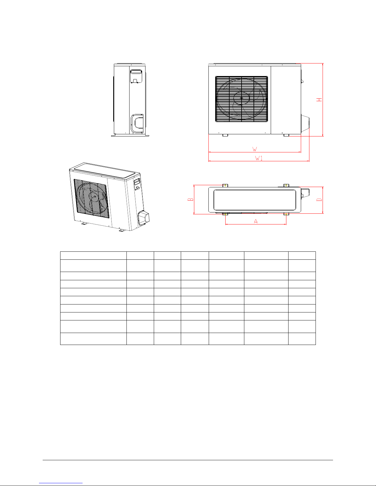
3. Dimensions
MODEL W D H W1 A B
M2OC-14HRDN1-Q
M2OC-14HRDN1
760 285 590 823 530 290
M2OC-18HRDN1 845 320 700 908 560 335
M2OC1-18HRDN1-Q 845 320 700 908 560 335
M3OC1-21HRDN1-Q 845 320 700 908 560 335
M3OC-27HRDN1 845 320 700 908 560 335
M3OC1-27HRDN1-Q 845 320 700 908 560 335
M4OC-24HRDN1-Q
845 320 700 908 560 335
M4OC-27HRDN1
M4OC1-27HRDN1-Q
900 315 860 980 590 333
M4OC-36HRDN1-Q
M5OA-36HRDN1-Q
990 345 965 1075 624 366
Page 6
ODMI-1103-A
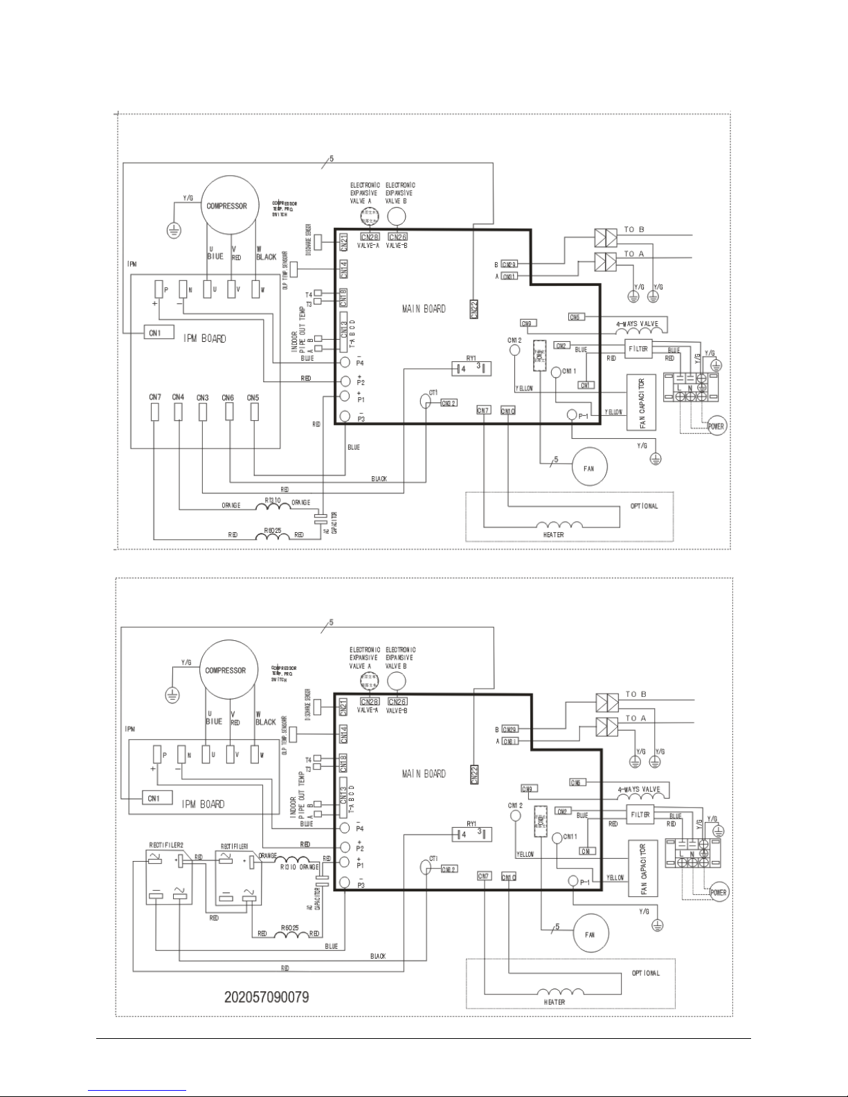
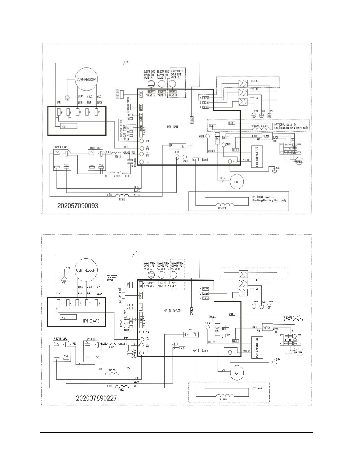
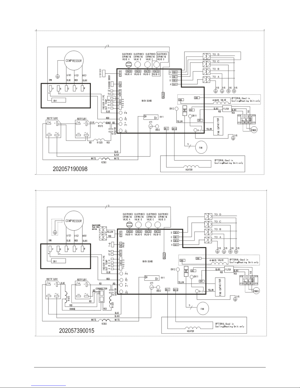
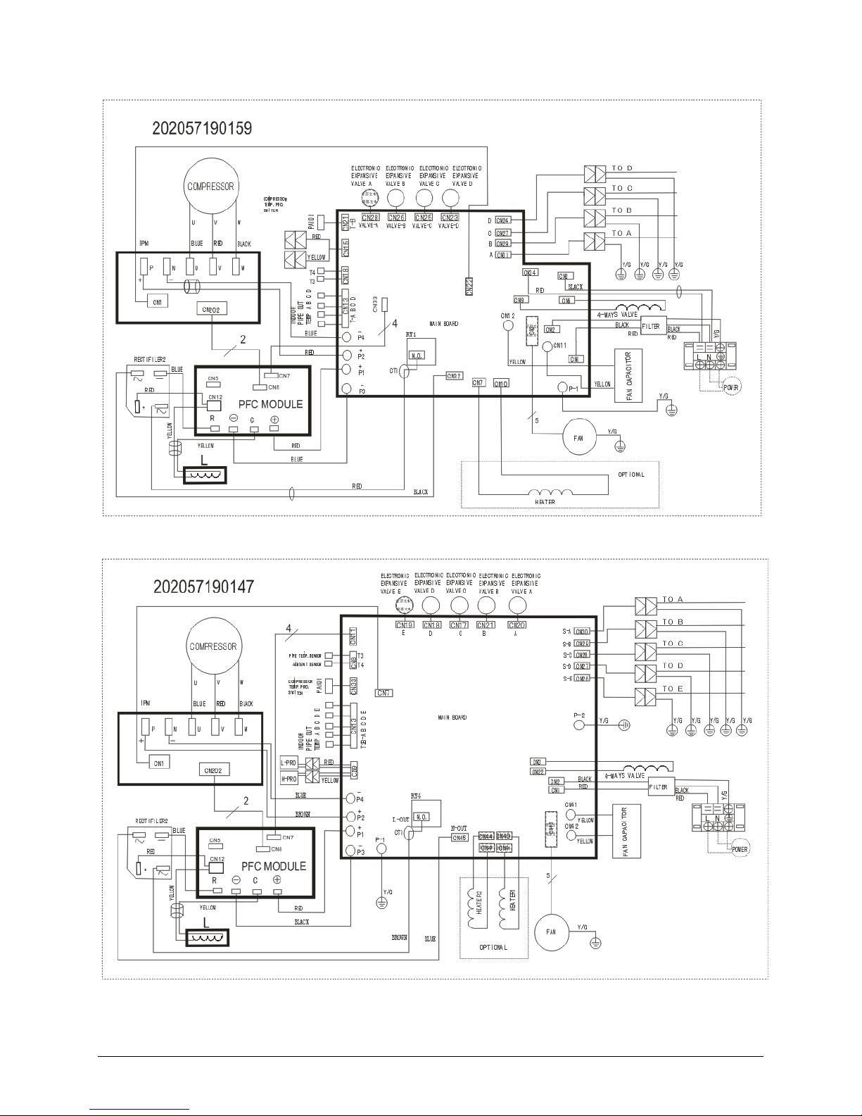
4. Wiring Diagram
4.1 M2OC-14HRDN1-Q
4.2 M2OC-14HRDN1
Page 7
ODMI-1103-A
4.3 M2OC1-18HRDN1-Q 、M3OC1-21HRDN1-Q
4.4 M2OC-18HRDN1、M3OC-27HRDN1
Page 8
ODMI-1103-A
4.5 M3OC1-27HRDN1-Q、M4OC-24HRDN1-Q
4.6 M4OC1-27HRDN1-Q、M4OC-27HRDN1
Page 9
ODMI-1103-A
4.7 M4OC-36HRDN1
4.8 M5OA-36HRDN1-Q
Page 10
ODMI-1103-A
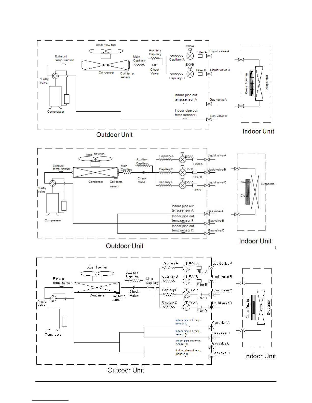
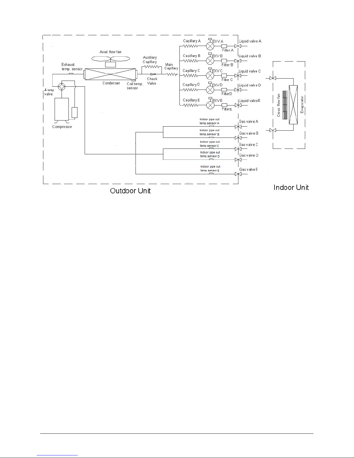
5. Refrigeration Cycle Diagram
5.1 Refrigeration circuit drawing of inverter binary type
4.2 Refrigeration circuit drawing of inverter trinary type
5.3 Refrigeration circuit drawing of inverter quadplex type
Page 11
ODMI-1103-A
5.4 Refrigeration circuit drawing of inverter quintuple type
Page 12

ODMI-1103-A
6. Indoor units combination
6.1 Indoor unit combination for M2OC-14HRDN1-Q、M2OC-14HRDN1
One unit Two unit
7 7+7 9+9
9 7+9 9+12
12 7+12
Note: There should be no more than one cassette or duct or console or ceiling & floor unit.
6.2 Indoor unit combination for M2OC1-18HRDN1-Q、M2OC-18HRDN1
One unit Two unit
7 7+7 9+9
9 7+9 9+12
12 7+12 12+12
18 7+18
Note: The 18k indoor unit should only be wall mounted unit.
6.3 Indoor unit combination for M3OC1-21HRDN1-Q
One unit Two unit Three unit
7 7+7 9+9 7+7+7 7+9+12
9 7+9 9+12 7+7+9 9+9+9
12 7+12 9+18 7+7+12 9+9+12
18 7+18 12+12 7+9+9
Note: There should be no more than one cassette or duct or console or ceiling & floor unit. And the 18k indoor unit
should only be wall mounted unit.
6.4 Indoor unit combination for M3OC1-27HRDN1-Q、M3OC-27HRDN1
One unit
Two unit Three unit
7 7+7 9+9 12+12 7+7+7 7+9+9 9+9+9
9 7+9 9+12 12+18 7+7+9 7+9+12 9+9+12
12 7+12 9+18 7+7+12 7+12+12 9+12+12
18 7+18 7+7+18
Note: The 18k indoor unit should only be wall mounted unit.
6.5 Indoor unit combination for M4OC-24HRDN1-Q
One unit Two unit Three unit Four unit
7 7+7 9+9 12+12 7+7+7 7+9+9 9+9+9 7+7+7+7 7+7+9+9 9+9+9+9
9 7+9 9+12 12+18 7+7+9 7+9+12 9+9+12 7+7+7+9 7+7+9+12 9+9+9+12
12 7+12 9+18 7+7+12 7+12+12 9+12+12 7+7+7+12 7+9+9+9
18 7+18 7+7+18 7+9+9+12
Note: The 18k indoor unit should only be wall mounted unit.
Page 13

ODMI-1103-A
6.6 Indoor unit combination for M4OC1-27HRDN1-Q、M4OC-27HRDN1
One unit Two unit Three unit Four unit
7 7+7 9+9 12+12 7+7+7 7+9+12 9+9+9 7+7+7+7 7+7+9+9 7+9+9+12
9 7+9 9+12 12+18 7+7+9 7+9+18 9+9+12 7+7+7+9 7+7+9+12 7+9+12+12
12 7+12 9+18 18+18 7+7+12 7+12+12 9+9+18 7+7+7+12 7+7+12+12 9+9+9+9
18 7+18 7+7+18 7+12+18 9+12+12 7+7+7+18 7+9+9+9 9+9+9+12
7+9+9 12+12+12 9+12+18
6.7 Indoor unit combination for M4OC-36HRDN1-Q
6.8 Indoor unit combination for M5OA-36HRDN1-Q
One Unit Two Unit Three Unit
7 7+7 9+12 7+7+7 7+9+18 9+9+18 12+18+18
9 7+9 9+18 7+7+9 7+12+12 9+12+12 18+18+18
12 7+12 12+12 7+7+12 7+12+18 9+12+18
18 7+18 12+18 7+7+18 7+18+18 9+18+18
9+9 18+18 7+9+9 9+9+9 12+12+12
7+9+12 9+9+12 12+12+18
Four Unit
7+7+7+7 7+7+9+18 7+9+9+18 7+12+18+18 9+9+18+18
7+7+7+9 7+7+12+12 7+9+12+12 9+9+9+9 9+12+12+12
7+7+7+12 7+7+12+18 7+9+12+18 9+9+9+12 9+12+12+18
7+7+7+18 7+7+18+18 7+9+18+18 9+9+9+18 12+12+12+12
7+7+9+9 7+9+9+9 7+12+12+12 9+9+12+12 12+12+12+18
7+7+9+12 7+9+9+12 7+12+12+18 9+9+12+18
Five Unit
7+7+7+7+7 7+7+7+9+18 7+7+9+12+18 7+9+9+12+18 9+9+9+12+12
7+7+7+7+9 7+7+7+12+18 7+7+12+12+18 7+9+12+12+12 9+9+9+12+18
7+7+7+7+12 7+7+7+18+18 7+9+9+9+9 7+9+12+12+18 9+9+12+12+12
7+7+7+7+18 7+7+9+9+9 7+9+9+9+12 9+9+9+9+9 9+12+12+12+12
7+7+7+9+9 7+7+9+9+12 7+9+9+9+18 9+9+9+9+12 12+12+12+12+12
7+7+7+9+12 7+7+9+9+18 7+9+9+12+12 9+9+9+9+18
One unit
Two unit Three unit Four unit
7 7+7 9+9 12+12 7+7+7 7+12+12 9+12+18 7+7+7+7 7+7+12+12 7+9+12+18 9+9+12+12
9 7+9 9+12 12+18 7+7+9 7+12+18 9+18+18 7+7+7+9 7+7+12+18 7+9+18+18 9+9+12+18
12 7+12 9+18 18+18 7+7+12 7+18+18 12+12+12 7+7+7+12 7+7+18+18 7+12+12+12 9+12+12+12
18 7+18
7+7+18
9+9+9 12+12+18 7+7+7+18 7+9+9+9 7+12+12+18 9+12+12+18
7+9+9 9+9+12 12+18+18 7+7+9+9 7+9+9+12 9+9+9+9 12+12+12+12
7+9+12 9+9+18 7+7+9+12 7+9+9+18 9+9+9+12 12+12+12+18
7+9+18 9+12+12
7+7+9+18 7+9+12+12 9+9+9+18
Page 14

ODMI-1103-A
7. Electronic control function
7.1 Abbreviation
T1: Indoor ambient temperature
T2: Coil temperature of indoor heat exchanger middle.
T2B: Coil temperature of indoor heat exchanger outlet.
T3: Coil temperature of outdoor heat exchanger
T4: Outdoor ambient temperature
T5: Compressor discharge temperature
Ts: Setting temp.
7.2 Electric Control working environment.
7.2.1 Input voltage: 190~264V.
7.2.2 Input power frequency:50Hz.
7.2.3 Indoor fan normal working amp. is less than 1A.
7.2.4 Outdoor fan. Normal working amp. is less than 1.5A.
7.2.5 Four-way valve normal working amp. is less than 1A.
7.2.6 Swing motor: DC12V.
7.3 Outdoor unit¡s digital display tube
There is a digital display tube in outdoor PCB.
Digital display tube display function
In standby , the LED displays ¡- -¡
In compressor operation, the LED display the running frequency,
In defrosting mode, The LED displays ¡dF¡ or alternative displays between running frequency and
¡dF¡(each displays 2s)
In compressor pre-heating, The LED displays ¡- -¡
In protection or malfunction, the LED displays error code or protection code.
7.4 Outdoor unit point check function
There is a check switch in outdoor PCB.
Push the switch SW1 to check the states of unit when the unit is running. The digital display tube will display
the follow procedure when push SW1 each time.
For units except M5OA-36HRDN1-Q model:
Display Remark
1
Indoor unit capacity demand code
2
Outdoor unit running mode code Off:0, Cooling:1, Heating:2
3
Amendatory capacity demand code
4
Outdoor unit fan motor state Off:0, Low speed:1, High speed:2
5
Evaporator outlet temp. for 1# indoor unit Actual data
6
Evaporator outlet temp. for 2# indoor unit Actual data
7
Evaporator outlet temp. for 3# indoor unit Actual data
8
Evaporator outlet temp. for 4# indoor unit Actual data
9
Condenser pipe temp. Actual data
10
Ambient temp. Actual data
11
Compressor discharge temp. Actual data
12
Inverter current Actual data
Page 15

ODMI-1103-A
13
EXV open angle for 1# indoor unit Actual data/8
14
EXV open angle for 2# indoor unit Actual data/8
15
EXV open angle for 3# indoor unit Actual data/8
16
EXV open angle for 4# indoor unit Actual data/8
17
Power supply of outdoor unit AD data
18 Indoor unit number The indoor unit can communicate with outdoor unit well.
19 The last error or protection code 00 means no malfunction
20
frequency value Actual data
21 Ambient temp. of 1# indoor unit Actual data
22 Condenser pipe temp. of 1# indoor unit Actual data
23
Ambient temp. of 2# indoor unit Actual data
24 Condenser pipe temp. of 2# indoor unit Actual data
25 Ambient temp. of 3# indoor unit Actual data
26
Condenser pipe temp. of 3# indoor unit Actual data
27 Ambient temp. of 4# indoor unit Actual data
28 Condenser pipe temp. of 4# indoor unit Actual data
29
―― Check point over
For M5OA-36HRDN1-Q model:
Display Remark
1
No.of indoor units in good connection Actual data
2
Outdoor unit running mode code Off:0, Cooling:2, Heating:3, Forced cooling:4
3
A indoor unit capacity
The capacity unit is horse power.If the indoor unit is not
connected,the digital display tube will show: “――”
4
B indoor unit capacity
5
C indoor unit capacity
6
D indoor unit capacity
7
E indoor unit capacity
8
A Indoor unit capacity demand code
9
B Indoor unit capacity demand code
10
C Indoor unit capacity demand code
11
D Indoor unit capacity demand code
12
E Indoor unit capacity demand code
13
Total indoor units amendatory capacity
demand code
14
The frequency corresponding to the total
indoor units amendatory capacity demand
15
The frequency after the frequency limit
16
The frequency sending to compressor contol
chip
17
A indoor unit evaporator outlet temp.(T2BA)
If the temp.is lower than -9 degree, the digital display tube will
show ¡-9¡.If the temp.is higher than 70 degree,the digital display
tube will show ¡70¡. If the indoor unit is not connected,the digital
display tube will show: “――”
18
B indoor unit evaporator outlet temp.(T2BB)
19
C indoor unit evaporator outlet temp.(T2BC)
20
D indoor unit evaporator outlet temp.(T2BD)
21
E indoor unit evaporator outlet temp.(T2BE)
22
A indoor unit room temp.(T1A)
23
B indoor unit room temp.(T1B)
24
C indoor unit room temp.(T1C)
25
D indoor unit room temp.(T1D)
26
E indoor unit room temp.(T1E)
Page 16

ODMI-1103-A
27
A indoor unit evaporator outlet temp.(T2BA)
If the temp.is lower than -9 degree, the digital display tube will
show ¡-9¡.If the temp.is higher than 70 degree,the digital display
tube will show ¡70¡. If the indoor unit is not connected,the digital
display tube will show: “――”
28
B indoor unit evaporator outlet temp.(T2BB)
29
C indoor unit evaporator outlet temp.(T2BC)
30
D indoor unit evaporator outlet temp.(T2BD)
31
E indoor unit evaporator outlet temp.(T2BE)
32
Condenser pipe temp.(T3)
33
Outdoor ambient temp.(T4)
34
Compressor discharge temp.(Tp) The display value is between 30~120 degree.If the temp.is lower
than 30 degree,the digital display tube will show ¡30¡.If the
temp.is higher than 99 degree, the digital display tube will show
single digit and tens digit.For example,the digital display tube
show ¡0.5¡,it means the compressor discharge temp.is 105
degree.)
35
AD value of current
The display value is hex number.
36
AD value of voltage
37
EXV open angle for A indoor unit
Actual data/4.
If the value is higher than 99, the digital display tube will show
single digit and tens digit.
For example,the digital display tube show ¡2.0¡,it means the EXV
open angle is 120¡ 4=480p.)
38
EXV open angle for B indoor unit
39
EXV open angle for C indoor unit
40
EXV open angle for D indoor unit
41
EXV open angle for E indoor unit
42
Frequency limit symbol
Bit7 0
The display
value is hex
number.For
example,the
digital display
tube show
2A,then Bit5=1,
Bit3=1, Bit1=1.
It means
frequency limit
caused by
T4,T3 and
current.
Bit6 0
Bit5
Frequency limit caused by T4.
Bit4
Frequency limit caused by T2.
Bit3
Frequency limit caused by T3.
Bit2
Frequency limit caused by Tp.
Bit1
Frequency limit caused by current
Bit0
Frequency limit caused by voltage
43
Average value of T2 (Sum T2 value of all indoor units)/(indoor units number)
44
Outdoor unit fan motor state Off:0, High speed:1, Med speed:2, Low speed:3
45
The last error or protection code 00 means no malfunction
7.4.1 Frequency of compressor:
Display Frequency of compressor (Hz)
30 30
-- Stand by
60 60
7.4.2 Running mode:
Display Corresponding mode
0 Off
1 Cooling mode
2 Heating mode
Page 17

ODMI-1103-A
7.4.3 Capacity demand:
Cooling mode
Capacity 2000-2
500
2000-2
500
3000-3
800
4500-5
000
5000-5
500
5500-6
100
6100-7
000
7000-7
500
7500-8
000
>7500
Correspondi
ng Code
1 2 3 4 5 6 7 8 9 >=10
Heating mode
Capacity 2000-2
500
2000-2
500
3000-3
800
4500-5
000
5500-6
100
6100-7
000
6100-7
000
7000-7
500
7500-8
000
>8000
Correspondin
g Code
1 2 3 4 5 6 7 8 9-10 >=11
Note:
The capacity is just for reference.
Page 18

ODMI-1103-A
7.4.4Number of indoor unit
Display Number of indoor unit
1 1
2 2
3 3
7.4.5 Outdoor ambient temp:
Display Corresponding temp.
Display
Corresponding
temp.
Display
Corresponding
temp.
15 -7.5 50 10 80 25
16 -7 51 10.5 81 25.5
17 -6.5 52 11 82 26
18 -6 53 11.5 83 26.5
19 -5.5 53 11.5 84 27
20 -5 54 12 85 27.5
21 -4.5 55 12.5 86 28
22 -4 56 13 87 28.5
23 -3.5 57 13.5 88 29
24 -3 58 14 89 29.5
26 -2 59 14.5 90 30
27 -1.5 60 15 91 30.5
28 -1 61 15.5 92 31
29 -0.5 62 16 93 31.5
30 0 63 16.5 93 31.5
31 0.5 63 16.5 94 32
32 1 64 17 95 32.5
33 1.5 65 17.5 96 33
34 2 65 17.5 97 33.5
35 2.5 66 18 98 34
36 3 67 18.5 99 34.5
37 3.5 68 19 10. 35~40
38 4 69 19.5 11. 40~45
39 4.5 70 20 12. 45~50
40 5 71 20.5 13. 50~55
41 5.5 72 21 14. 55~60
42 6 73 21.5 15. 60~65
43 6.5 74 22 16. 65~70
44 7 75 22.5
45 7.5 75 22.5
46 8 76 23
47 8.5 77 23.5
48 9 78 24
49 9.5 79 24.5
Page 19

ODMI-1103-A
7.4.6 Opening degree of electronic expansion valve:
Opening degree equals the display data times 8
7.5 Protection
7.5.1 Three minutes delay at restart for compressor.
7.5.2 Temperature protection of compressor discharge.
When the compressor discharge temp. is getting higher, the running frequency will be limited as below
rules:
----If 102℃<T5<115 , decrease the freq℃ uency to the lower level every 2 minutes till to F1.
---If T5>115℃ for 10 seconds, the compressor will stop and restart till T5<90℃.
7.5.3 Under voltage protection
VOLLIMT1
VOLTAGE
No limit
VOLLIMT2
VOLLIMT3
Off
VOLFRE2
VOLFRE1
VOLREL1
VOLREL2
VOLREL3
Mode VOLLIMT1(V) VOLLIMT2(V) VOLLIMT3(V) VOLREL1(V) VOLREL2(V) VOLREL3(V) VOLFRE1(Hz) VOLFRE2(Hz)
M2OC-14HRDN1 220 200 80 250 210 100 62 54
M2OC-14HRDN1-Q 220 200 80 250 210 100 62 54
M2OC-18HRDN1 230 200 80 260 210 100 62 54
M2OC1-18HRDN1-Q
230 200 120 260 210 135 62 54
M3OC1-21HRDN1-Q
245 220 80 265 240 100 78 45
M3OC-27HRDN1 245 220 80 265 240 100 78 45
M3OC1-27HRDN1-Q
245 220 120 265 240 135 78 45
M4OC-24HRDN1-Q 245 220 120 265 240 135 78 45
M4OC-27HRDN1 221 210 80 260 225 100 62 54
M4OC1-27HRDN1-Q
221 210 80 260 225 100 53 44
M4OC-36HRDN1-Q 200 185 80 210 195 100 54 42
For M5OA-36HRDN1-Q,
VOLT_RST1_ADD
VOLTAGE
No limit
VOLT_LTM1_ADD
VOLT_RST2_ADD
VOLT_LTM2_ADD
VOLT_LTM_FREQ1_ADD
VOLT_LTM_FREQ2_ADD
Page 20

ODMI-1103-A
VOLT_RST1_ADD=210V, VOLT_LIM1_ADD=200V, VOLT_RST2_ADD=195V, VOLT_LIM2_ADD=185V.
VOLT_LIM_FREQ1_ADD=54Hz, VOLT_LIM_FREQ2_ADD=42Hz.
7.5.4 Compressor current limit protection
If the compressor current exceeds the current limit value for 10 seconds, the compressor frequency will be
limited as below table.
For models except M5OA-36HRDN1-Q.
Cooling mode:
Current frequency(Hz) Current limit value(A) Frequency limit
COOL_F10 ICOOLLMT6 Decrease the frequecny to COOL_F4 and
run at COOL_F4 for 3 minutes.
After that,the frequency will be adjusted
according to the capacity demand and rise
to the upper level every 3 minutes
(When the frequency>COOL_F4 via
capacity demand).
COOL_F9 ICOOLLMT5
COOL_F8 ICOOLLMT4
COOL_F7 ICOOLLMT3
COOL_F6 ICOOLLMT2
COOL_F5 ICOOLLMT1
If the current frequency is lower than COOL_F4, the frequency will not be limited.
After 10s of the compressor start, if the current>ICOOL,the AC will display the failure for 30 seconds
and stop. The AC will restart 3 minutes later.
Heating mode:
Current frequency(Hz) Current limit value(A) Frequency limit
HEAT_F12 IHEATLMT8 Decrease the frequecny to HEAT_F4 and
run at HEAT_F4 for 3 minutes.
After that,the frequency will be adjusted
according to the capacity demand and rise
to the upper level every 3 minutes
(When the frequency>Heat_F4 via capacity
demand).
HEAT_F11 IHEATLMT7
HEAT_F10 IHEATLMT6
HEAT_F9 IHEATLMT5
HEAT_F8 IHEATLMT4
HEAT_F7 IHEATLMT3
HEAT_F6 IHEATLMT2
HEAT_F5 IHEATLMT1
If the current frequency is lower than HEAT_F4, the frequency will not be limited.
After 10s of the compressor start, if the current>IHEAT,the AC will display the failure for 30 seconds
and stop. The AC will restart 3 minutes later.
For M5OA-36HRDN1-Q model:
Cooling mode:
Current frequency
(Hz)
Current limit value(A)
Frequency limit
COOL_F16 ICOOLLMT12 Decrease the frequecny to COOL_F4 and run at
COOL_F4 for 3 minutes.
After that,the frequency will be adjusted according to
the capacity demand and rise to the upper level every
3 minutes
(When the frequency>COOL_F4 via capacity
demand).
COOL_F15 ICOOLLMT11
COOL_F14 ICOOLLMT10
COOL_F13 ICOOLLMT9
COOL_F12 ICOOLLMT8
COOL_F11 ICOOLLMT7
COOL_F10 ICOOLLMT6
Page 21

ODMI-1103-A
COOL_F9 ICOOLLMT5
COOL_F8 ICOOLLMT4
COOL_F7 ICOOLLMT3
COOL_F6 ICOOLLMT2
COOL_F5 ICOOLLMT1
If the current frequency is lower than COOL_F4, the frequency will not be limited.
After 10s of the compressor start, if the current>ICOOL,the AC will display the failure for 30 seconds
and stop. The AC will restart 3 minutes later.
Heating mode:
Current frequency
(Hz)
Current limit value(A)
Frequency limit
HEAT_F16 IHEATLMT12 Decrease the frequecny to HEAT_F4 and run at
HEAT_F4 for 3 minutes.
After that,the frequency will be adjusted according to
the capacity demand and rise to the upper level every
3 minutes
(When the frequency>Heat_F4 via capacity
demand).
HEAT_F15 IHEATLMT11
HEAT_F14 IHEATLMT10
HEAT_F13 IHEATLMT9
HEAT_F12 IHEATLMT8
HEAT_F11 IHEATLMT7
HEAT_F10 IHEATLMT6
HEAT_F9 IHEATLMT5
HEAT_F8 IHEATLMT4
HEAT_F7 IHEATLMT3
HEAT_F6 IHEATLMT2
HEAT_F5 IHEATLMT1
If the current frequency is lower than HEAT_F4, the frequency will not be limited.
After 10s of the compressor start, if the current>IHEAT,the AC will display the failure for 30 seconds
and stop. The AC will restart 3 minutes later.
6.5.5 Indoor / outdoor units communication protection
If the indoor units can not receive the feedback signal from the outdoor units for 2 minutes,the AC will stop
and display the failure.
7.5.6 High condenser coil temp. protection.
When T3>65 for ℃ 3 seconds, the compressor will stop while the indoor fan and outdoor fan will continue.
When T3<52 , the protection will release℃ and the compressor will restart after 3 minutes.
7.5.7 Outdoor unit anti-freezing protection
When T2B<0 for 250 seconds℃ ,the indoor unit capacity demand will be zero and resume to normal when
T2B>10 .℃
7.5.8 Oil return
Running rules:
Page 22

ODMI-1103-A
1. If the compressor frequency keeps lower than RECOILINFRE for Te minutes,the AC will rise the
frequency to RECOILFRE for Tf seconds and then resume to former frequency.For M4OC-36HRDN1-Q,
RECOILINFRE=45Hz, RECOILFRE=48Hz,Te=120,Tf=180; For M5OA-36HRDN1-Q, RECOILINFRE=45Hz,
RECOILFRE=48Hz, Te=90,Tf=100; For other models, RECOILINFRE=50Hz, RECOILFRE=62Hz,
Te=120,Tf=180.
2. During the Tf seconds, the EXV and indoor units keep the current running mode(except
M5OA-36HRDN1-Q model), the frequency will not be limited by the compressor discharge temp.and the
current.For M5OA-36HRDN1-Q model,the EXV will keep 300p while the indoor units will keep the current
running mode.
3. If the outdoor ambient is higher than 15℃ during the oil return,the AC quit oil return.
7.5.9 Compressor preheating functions
----Preheating permitting condition:
If T4(outdoor ambient temperature)<3 and the machine connects to power suppl℃ y no longer than 5
seconds or if T4<3 and compressor has stopped for over 3 hours, the compressor heating cable will ℃
work.
----Preheating mode:
A weak current flow through the coil of compressor from the wiring terminal of compressor, then the
compressor is heated without operation.
----Preheating release condition:
If T4≧5 or ℃ the compressor starts running, preheating function will stop.
7.5.10 Compressor crankcase heater
When T4<3℃ and the compressor is not running,the crankcase heater will be active.
When T4≧5℃ or the compressor starts up,the crankcase heater will stop work.(For M5OA-36HRDN1-Q,T4
≧8℃)
Page 23

ODMI-1103-A
8. Troubleshooting
8.1 Indoor unit error code explanation:
R series(except model MSR1I-07HRDN1-Q&MSR1I-09HRDN1-Q)+X series+Y series:
Display
MALFUNCTION
E0 EEPROM parameter error
E1 Indoor / outdoor units communication protection
E2 Zero-crossing signal error
E3 Fan speed out of control
E5 Open or short circuit of outdoor temperature sensor
E6 Open or short circuit of room or evaporator temperature sensor
P0 IGBT over-strong current protection
P1 Over voltage or too under voltage protection
P2 Temperature protection of compressor top.
P4 Inverter compressor drive error
9V series+VERTU series
NO.
MALFUNCTION DEF TIMER AUTO RUN
DISPLAY
DIGITAL TUBE
1 EEPROM error
O O O O E0
2 Indoor / outdoor units communication protection
☆ ☆ ☆ ☆ E1
3 Zero-crossing signal error
O O
☆ ☆
E2
4 Indoor fan speed out of control O O
☆ ☆ E3
5
Outdoor unit temp. sensor or connector of temp. sensor is
defective
X O X
☆
E5
6
Open or short circuit of room or evaporator temperature
O O O
☆
E6
7 Outdoor fan speed out of control O O
☆ ☆ E7
8 IBM malfunction or IGBT over-strong current protection X X O ☆
P0
9
Over voltage or too under voltage protection X O O
☆
P1
10
Temperature protection of compressor top. O
X X
☆
P2
11 Compressor position protection
O X ☆ ☆ P4
12 Inverter module protection
X O ☆ ☆ P5
☆ Flash(at 0.5Hz, P5 at 0.25Hz) O light X(off)
9A series+R series(Only for model MSR1I-07HRDN1-Q&MSR1I-09HRDN1-Q)
NO.
MALFUNCTION DEF TIMER AUTO RUN
DISPLAY
DIGITAL TUBE
1 EEPROM error
O O O O E0
2 Indoor / outdoor units communication protection
☆ ☆ ☆ ☆ E1
3 Zero-crossing signal error
O O
☆ ☆
E2
4 Indoor fan speed out of control O O
☆ ☆ E3
5
Outdoor unit temp. sensor or connector of temp. sensor is
defective
X O X ☆
E5
6
Open or short circuit of room or evaporator temperature
O O O
☆
E6
7 Outdoor fan speed out of control
☆
O
☆ ☆ E7
8 IBM malfunction or IGBT over-strong current protection X X O ☆
P0
9
Over voltage or too under voltage protection X O O
☆
P1
10
Temperature protection of compressor top. O X X
☆
P2
11 Compressor position protection
O X ☆ ☆ P4
12 Inverter module protection
X O ☆ ☆ P5
☆ Flash(at 0.5Hz, P5 at 0.25Hz) O light X(off)
Page 24

ODMI-1103-A
Cassette/Ceiling&Floor series:
Operation Timer De-frost Alarm LED STATUS
X X X Indoor room temp. sensor open or short-circuit
X X ★ X Indoor pipe temp. sensor open or short-circuit
X
X X Indoor and outdoor communication error
X X X ★ Water level alarm
X X EEPROM error
X X
Inverter module protection
X X Outdoor sensor open or short circuit
X
Outdoor voltage protection
X
X Compressor top temp. protection
X
Mode conflict
X
Outdoor current protection
flash, light, X extinguished.
A5 Duct:
Operation Timer De-frost Alarm LED STATUS
DISPLAY
DIGITAL
TUBE
★ X X X
Indoor room temp. sensor open or
short-circuit
E0
X X ★ X
Indoor pipe temp. sensor open or
short-circuit
E1
X ★ X X
Indoor and outdoor communication
error
E2
X X X ★ Water level alarm
E3
★ ★ X X EEPROM error
E4
★ X X
Inverter module protection
E5
★
X X Outdoor sensor open or short circuit
E6
★ ● ★
X Outdoor fan speed out of control
E7
★
X
Outdoor voltage protection
P0
★ ★ ★ ★ Compressor top temp. protection
P3
★ ◎
X X Compressor position. protection
P4
★ X
X Mode conflict
P5
flash at 5Hz, light, X extinguished ◎flash at 0.5Hz
Page 25

ODMI-1103-A
8.2 Outdoor unit error code explanation:
For units(except M5OA-36HRDN1-Q model)
Display LED STATUS
E0 EEPROM error
E1 No A Indoor unit coil outlet temp. sensor or connector of sensor is defective
E2 No B Indoor unit coil outlet temp. sensor or connector of sensor is defective
E3 No C Indoor unit coil outlet temp. sensor or connector of sensor is defective
E6 No D Indoor unit coil outlet temp. sensor or connector of sensor is defective
E4 Outdoor unit temp. sensor or connector of temp. sensor is defective
E5 Compressor voltage protection
E7 Communication malfunction between outdoor main chip and compressor control chip
P0
Temperature protection of compressor discharge or compressor top.
For M4OC-36HRDN1-Q,it only means compressor discharge temp.protection.
P1 High pressure protection(only for M4OC1-27HRDN1-Q, M4OC-36HRDN1-Q)
P2 Low pressure protection(only for M4OC1-27HRDN1-Q, M4OC-36HRDN1-Q)
P3 Compressor current protection
P4 Inverter module protection
P6 Condenser high-temperature protection
Page 26

ODMI-1103-A
For M5OA-36HRDN1-Q model
Display LED STATUS
E0 EEPROM error
E2 Communication malfunction between outdoor unit and indoor units
E3 Communication malfunction between outdoor main chip and compressor control chip.
E4 Outdoor unit temp. sensor or connector of temp. sensor is defective
E5 Compressor voltage protection
E6 PFC module protection
F1 No A Indoor unit coil outlet temp. sensor or connector of sensor is defective
F2 No B Indoor unit coil outlet temp. sensor or connector of sensor is defective
F3 No C Indoor unit coil outlet temp. sensor or connector of sensor is defective
F4 No D Indoor unit coil outlet temp. sensor or connector of sensor is defective
F5 No E Indoor unit coil outlet temp. sensor or connector of sensor is defective
P0 Compressor top. temperature protection
P1 High pressure protection
P2 Low pressure protection
P3 Compressor current protection
P4 Compressor discharge high-temperature protection
P5 Condenser high-temperature protection
P6 Inverter module protection
Page 27

ODMI-1103-A
8.3Trouble shooting
8.3.1 EEPROM parameter error diagnosis and solution
8.3.2 Indoor / outdoor units communication protection(Only for M5OA-36HRDN1-Q model)
Shut off the power supply and turn on it 5s later
The problem comes out again
Is the EEPROM chip plugged in PCB well?
No
Correct the connection
Replace the
PCB
Disconnect the power supply, after 1
minute, connect the power supply , turn on
the unit with remote controller
Does the unit work
normally ?
Check the wiring between
indoor and outdoor unit. Is
the connection of L, N, S
and GND good?
Is the GND connection on
outdoor PCB good?
No
No
Reconnect and retest
Is the LED4(red) on
outdoor PCB bright and
LED1(yellow) blinking?
Replace outdoor e-box.
Yes
Yes
The power supply for
outdoor PCB is fail. Check
the wiring on outdoor PCB
comparing with wiring plate.
Is the connection good?
No
Correct the connection
.
Yes
No
Replace indoor PCB
and repower on. Is
the failure cleared?
No
Page 28

ODMI-1103-A
8.3.3 Zero-crossing signal error
8.3.4 Fan speed out of control diagnosis
Is the indoor fan motor connector and
connection good?
The unit does not work normally
Turn off the unit, rotate the indoor
fan.Does it rotate freely?
No
Disassemble the connection
between fan and motor, check if the
bearing is normal. If not, change the
bearing.If yes, follow the below step.
Replace the indoor fan motor
Yes
Replace the indoor PCB
No
Yes
Check the voltage of motor power
input .Is it in range of AC90-160V?
Yes
Shut off the power supply and turn on it 5s later
Is power supply and
connection of
connectors good?
Indoor PCB is defective.
Replace the indoor PCB.
Be sure the power supply
is good and correct the
connection
No
Yes
Page 29

ODMI-1103-A
8.3.5 Open or short circuit of temperature sensor diagnosis and solution.
8.3.6 Compressor voltage protection
Yes
Replace outdoor PCB
Yes
Check the connections between
the sensors and the PCB. Are the
connections good?
Replace the sensor and check if
the errors happen again?
Check the voltage of power supply, if the voltage is about 220V, turn off the power
supply to indoor unit and turn it on again after 1 minute
Does the trouble occur again?
Check the voltage of P,N port in IPM board.
If it is not higher than 310V, follow the below step.
Replace the IPM board
Yes
No
Page 30

ODMI-1103-A
8.3.7 Communication malfunction between outdoor main chip and compressor control chip.
Check whether the IPM board has error display
Replace the IPM board
Replace the electric control box
No
No
Yes
Replace the outdoor PCB
No
Page 31

ODMI-1103-A
8.3.8 Temperature protection of compressor discharge or compressor top.
Yes
Does
compressor
operate?
Is the
connection
good?
Is refrigerant
circulation
volume
normal?
No
No
Charge
refrigerant
Is abnormality
the same after
gas charging?
No
Check refrigerant system
(such as clogging of
capillary, etc)
Reconnect and retest.
No
Yes
Is protector
normal?
Replace the protector.
No
Yes
Check the
outdoor main
PCB. Is there
some problem?
Replace the outdoor
PCB.
Yes
Page 32

ODMI-1103-A
8.3.9 Compressor current protection
Check the resistance of compressor, is it
normal?
Turn one indoor unit only, Does the compressor start
after 3 minutes?
Does the trouble occur again after compressor
running some time?
No
Yes
No
The compressor is defective
Check the refrigerant circulation volume and pressure
No
The compressor is defective
Yes
If refrigerant circulation volume and pressure is OK, change the outdoor main PCB.
Page 33

ODMI-1103-A
8.3.10 Inverter module protection
8.3.11 Condenser high-temperature protection
When outdoor pipe temp. is more than 65¡C, the unit will stop, and unit runs again when outdoor pipe
temp. less than 52¡C.
Is the outdoor pipe temp. more than 65¡C ?
Is the outdoor pipe temp sensor right according to the annex 1
Replace the outdoor main board
No
Yes
Replace the outdoor pipe temp sensor
No
Replace inverter compressor
Repair connector
If the problem comes to again, check wingding resistance of inverter compressor, is it right?
Replace the IPM board
Are the U,V,W connected to compressor and inverter module right?
Yes
No
No
Page 34

ODMI-1103-A
8.3.12 PFC module protection
No
No
Yes
Check whether the power
supply of bridge rectifiers
output port is 325VDC
Replace bridge rectifiers
Does the unit work
normally ?
No
Check whether the
power supply of bridge
rectifiers input port is
normal.
Replace the
outdoor PCB
Yes
Replace the PFC inductance
Check whether the
voltage between P and
N port in IPM is 380V.
No
Replace outdoor e-box.
Yes
Check whether the
wiring between PCB
and PFC module is
normal.
Yes
No
Check the voltage of power supply, if the voltage
is about 220V, turn off the power supply and
turn it on again after 1 minute
Yes
Check whether
the PFC
inductance is
normal.
Replace PFC
Page 35

ODMI-1103-A
Annex 1
Characteristic of temp. sensor
Temp.℃ Resistance KΩ
Temp.℃ Resistance KΩ
Temp.℃ Resistance KΩ
-10 62.2756 17 14.6181 44 4.3874
-9 58.7079 18 13.918 45 4.2126
-8 56.3694 19 13.2631 46 4.0459
-7 52.2438 20 12.6431 47 3.8867
-6 49.3161 21 12.0561 48 3.7348
-5 46.5725 22 11.5 49 3.5896
-4 44 23 10.9731 50 3.451
-3 41.5878 24 10.4736 51 3.3185
-2 39.8239 25 10 52 3.1918
-1 37.1988 26 9.5507 53 3.0707
0 35.2024 27 9.1245 54 2.959
1 33.3269 28 8.7198 55 2.8442
2 31.5635 29 8.3357 56 2.7382
3 29.9058 30 7.9708 57 2.6368
4 28.3459 31 7.6241 58 2.5397
5 26.8778 32 7.2946 59 2.4468
6 25.4954 33 6.9814 60 2.3577
7 24.1932 34 6.6835 61 2.2725
8 22.5662 35 6.4002 62 2.1907
9 21.8094 36 6.1306 63 2.1124
10 20.7184 37 5.8736 64 2.0373
11 19.6891 38 5.6296 65 1.9653
12 18.7177 39 5.3969 66 1.8963
13 17.8005 40 5.1752 67 1.830
14 16.9341 41 4.9639 68 1.7665
15 16.1156 42 4.7625 69 1.7055
16 15.3418 43 4.5705 70 1.6469
Page 36

ODMI-1103-A
Annex 2
1. Reference voltage data:
a) Rectifier : Input :220-230V(AC), output :310V(DC)
b) Inverter module: U,V, W 3ph.
Result
U-V 60-150V(AC)
U-W 60-150V(AC)
V-W 60-150V(AC)
P-N DC
310V
c) Photo-couple PC817, PC851: Control side <+5V, AC side :< 24V(AC)
d) S terminal and N: changeable from 0-24V
2. Check the Diode Bridge component ( In wiring diagram, rectifier)
Remark: If this part is abnormal, the LED will not light.
Multi-meter Result
Forward Resistance Backward Resistance
+ _
Infinite Infinite
~
+
~500 ohm Infinite
~ - ~
~500 ohm Infinite
~
~ +
- ~
 Loading...