

Midea M3OD-21HFN1-Q, M2OD-16HFN1-Q, M3OD-26HFN1-Q, M3OD-27HFN1-Q, M4OD-28HFN1-Q Service Manual
...Page 1

SERVICE MANUAL
MIDEA AIRCONDITIONER
EUROPE MARKET
SUPER DC INVERTER MULTI TYPE
M2OD-14HFN1-Q
M2OD-16HFN1-Q
M2OD-18HFN1-Q
M3OD-21HFN1-Q
M3OD-26HFN1-Q
M3OD-27HFN1-Q
M4OD-28HFN1-Q
M4OA-36HFN1-Q
M5OC-36HFN1-Q
M5OD-42HFN1-Q
DC MULTI OUTDOOR UNITS
Page 2

CONTENTS
1. General information of Outdoor Units .......................................... 3
2. Features .......................................................................................... 4
3. Dimensions ..................................................................................... 5
4. Wiring Diagram ............................................................................. 12
5. Refrigeration Cycle Diagram ....................................................... 16
6. Indoor units combination ............................................................ 19
7. Sound Levels ................................................................................ 22
8. Installation Details ........................................................................ 23
9. Electronic control function .......................................................... 34
10. Troubleshooting ......................................................................... 40
Page 3
1. General information of Outdoor Units
Model name
Dimension (mm)
Compressor
M2OD-14HFN1-Q
845x320x700
DA130M1C-31FZ
M2OD-16HFN1-Q
810x310x558
ASN108D22UEZ
M2OD-18HFN1-Q
810x310x558
DA130M1C-31FZ
M2OD-18HFN1-Q
845x320x700
DA150S1C-20FZ
M3OD-21HFN1-Q
845x320x700
DA150S1C-20FZ
M3OD-26HFN1-Q
845x320x700
DA150S1C-20FZ
M3OD-27HFN1-Q
900x315x860
DA250S2C-30MT
M4OD-28HFN1-Q
900x315x860
DA250S2C-30MT
M4OA-36HFN1-Q
990x345x965
TNB306FPGMC-L
M5OC-36HFN1-Q
990x345x965
TNB306FPGMC-L
M5OD-42HFN1-Q
990x345x965
MNB36FAAMC-L
Page 4

2. Features
The hydrophilic fin can improve the heating efficiency at operation mode.
It protects the valves and prevents water from dripping.
4 way valve control
It is only operated in the heating operation mode except defrosting operation.
Outdoor unit
Power relay control
Hydrophilic aluminum fin
Anti-rust cabinet
Valve protection cover
Low noise air flow system
Discharge pipe temperature protection
Page 5
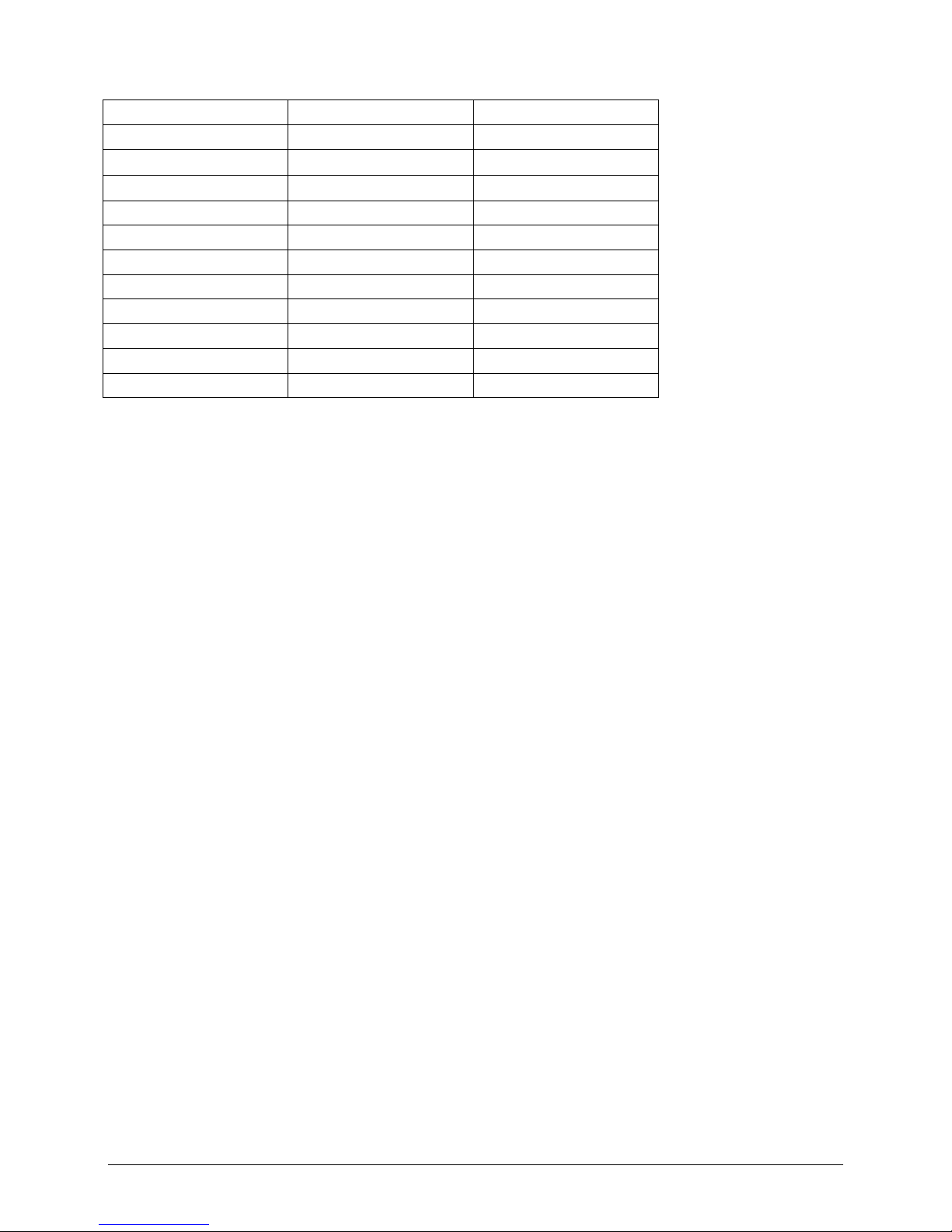
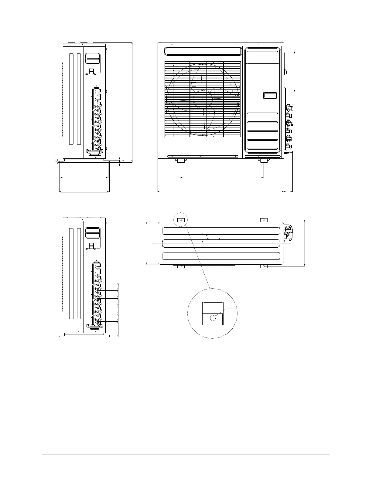
3. Dimensions
M2OD-14HFN1-Q, M2OD-18HFN1-Q
560 W1
H
6
D1 335
D2 360
845 W
313
D3
335
D1
R6
R5
A1
22
A2
50
B1
120
110
B2
700
W2
73
58
58
58
110
H1
H2
200.7
243.6
L1
L2
Page 6
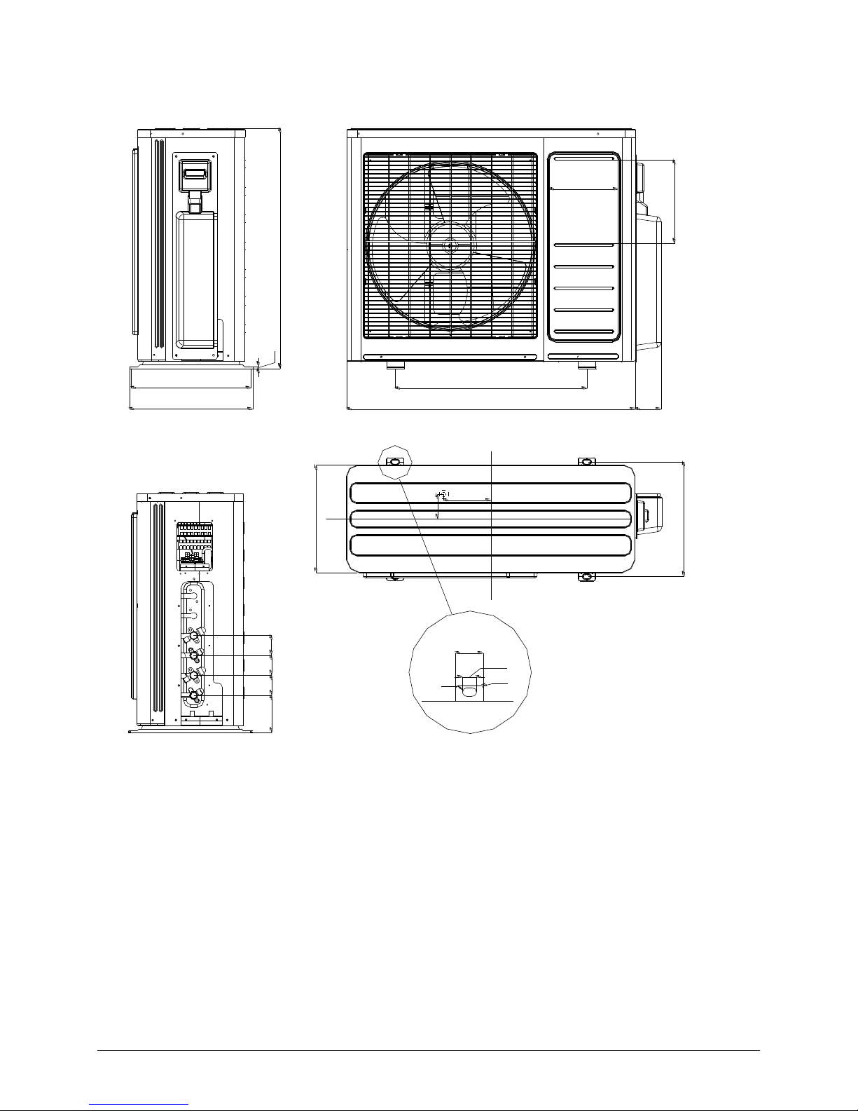
M2OD-16HFN1-Q, M2OD-18HFN1-Q(W190)
D2 348
558
H
W2
64
795 W
549 W1
810 W3
A2
61.6
A1
25.4
R20
R7.7
289
D3
D1 325
10
B1
66.6
B2
104.2
50 H1
90 H2
Page 7
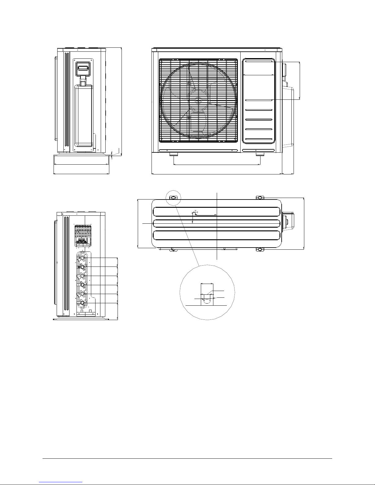
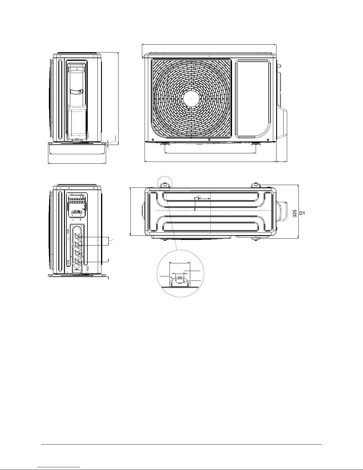
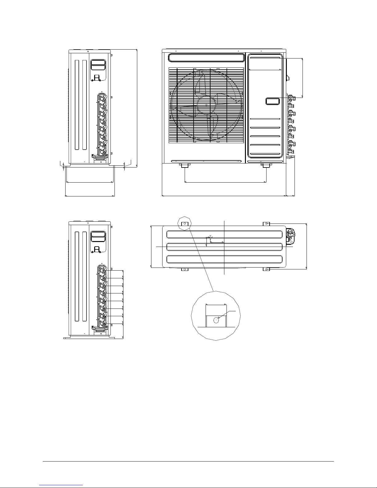
M3OD-21HFN1-Q, M3OD-26HFN1-Q
560 W1
H
6
D1 335
D2 360
845 W
313
D3
335
D1
R6
R5
A1
22
A2
50
B1
120
110
B2
700
W2
73
58
58
58 58
58
110
H1
H2
200.7
243.6
L1
L2
Page 8
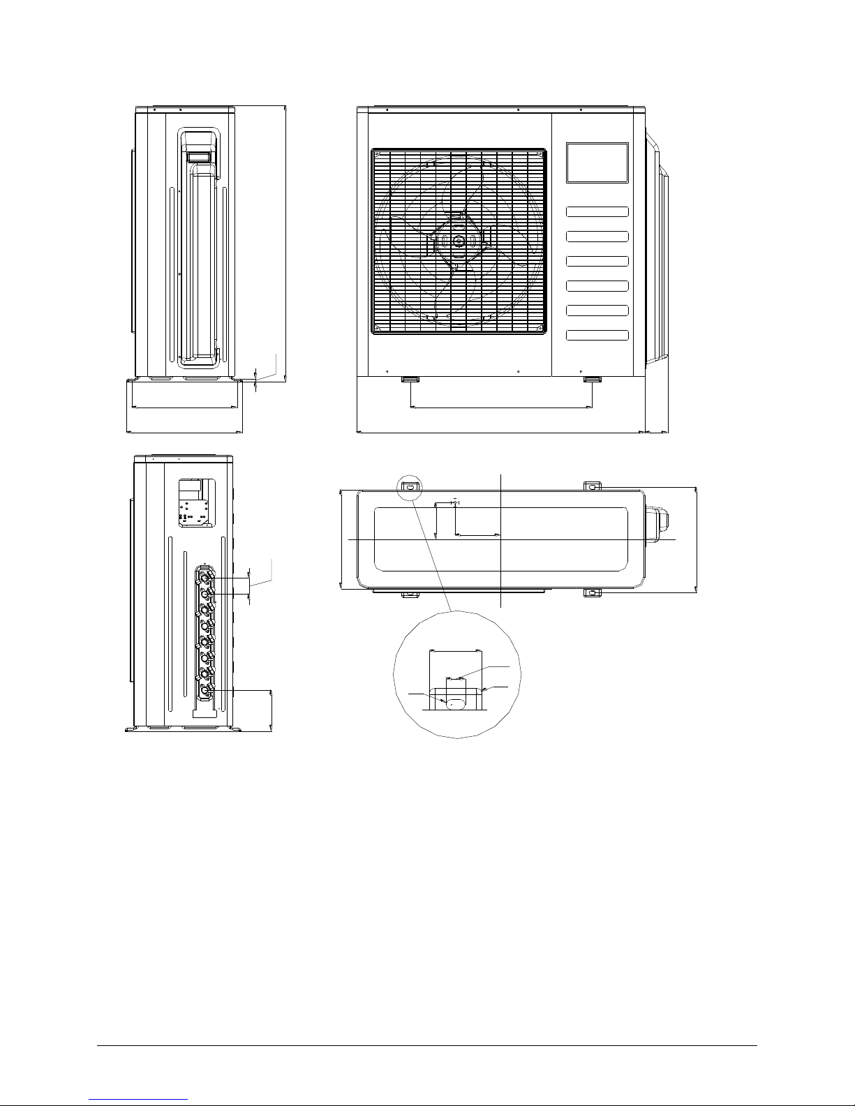
M3OD-27HFN1-Q
900 W
590 W1
860
H
12
D2 355
D1 333
302
D3
333
D1
50
97
90
B2
B1
8
A2
5555 55 55 55110
62
W2
H1
H2
R6
238.4
285.7
L1
L2
Page 9
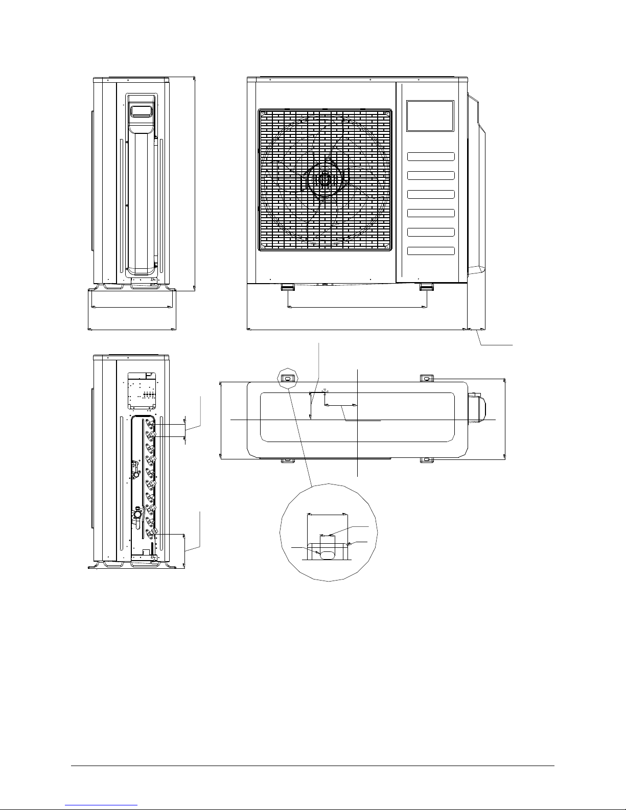
M4OD-28HFN1-Q
900 W
590 W1
860
H
12
D2 355
D1 333
302
D3
333
D1
50
97
90
B2
B1
8
A2
5555 55 55 55 55 55110
62
W2
H1
H2
R6
238.4
285.7
L1
L2
Page 10
M4OA-36HFN1-Q
624 W1
990 WD2 397
D1 366
965
10
H
78
W2
340
366
D3
D1
125
145
B1
B2
60
22
A2
A1
55
140
H1
H2
R5
R6
Page 11
M5OC-36HFN1-Q, M5OD-42HFN1-Q
990 W
W2 81
624 W1
D2 397
D1 366
55 H1
965 H
153 H2
366 D1
B2 125
B1 145
D3 345
60
22
A2
A1
R5
R6
Page 12
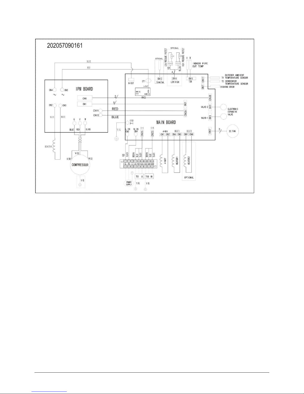
4. Wiring Diagram
M2OD-14HFN1-Q, M2OD-18HFN1-Q
Page 13
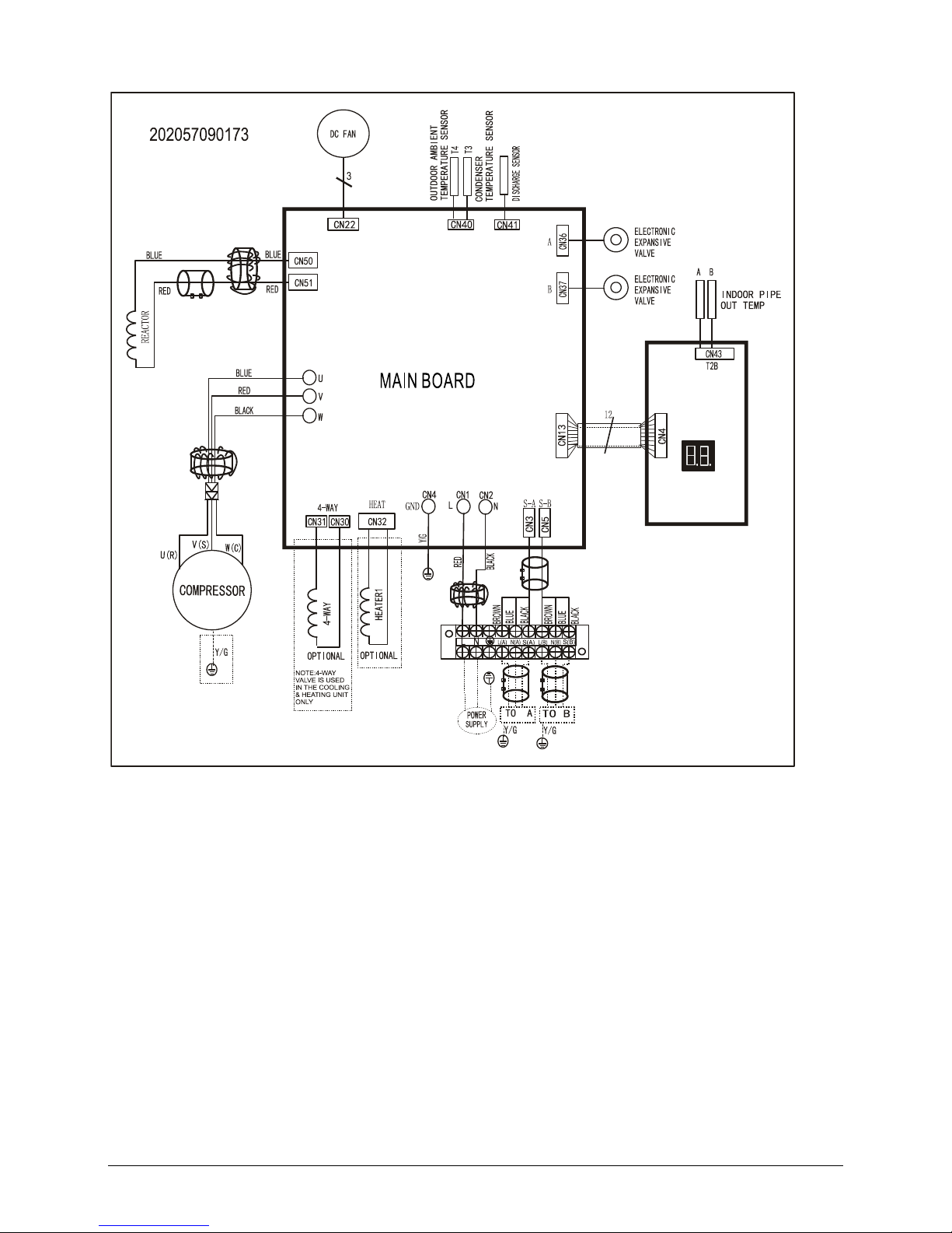
M2OD-16HFN1-Q, M2OD-18HFN1-Q(W190)
Page 14
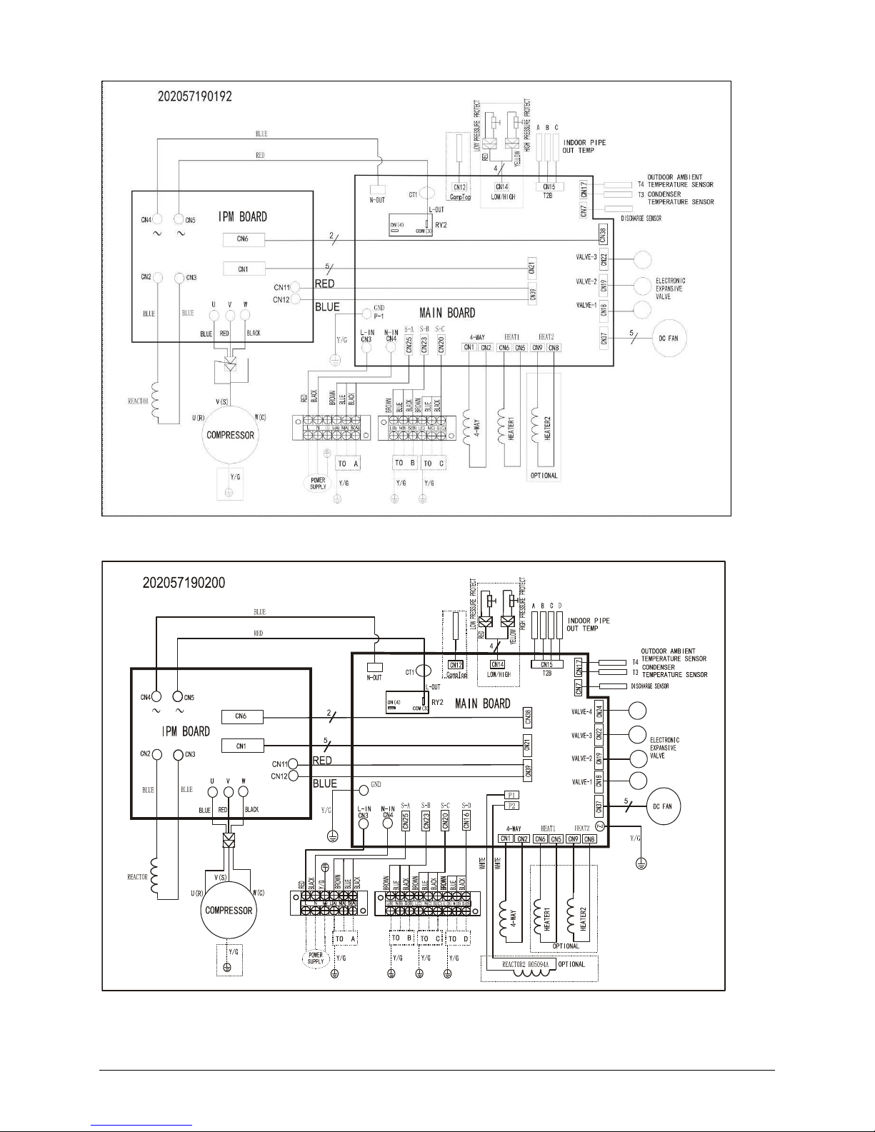
M3OD-27HFN1-Q, M3OD-21HFN1-Q, M3OD-26HFN1-Q
M4OD-28HFN1-Q
M4OA-36HFN1-Q
Page 15
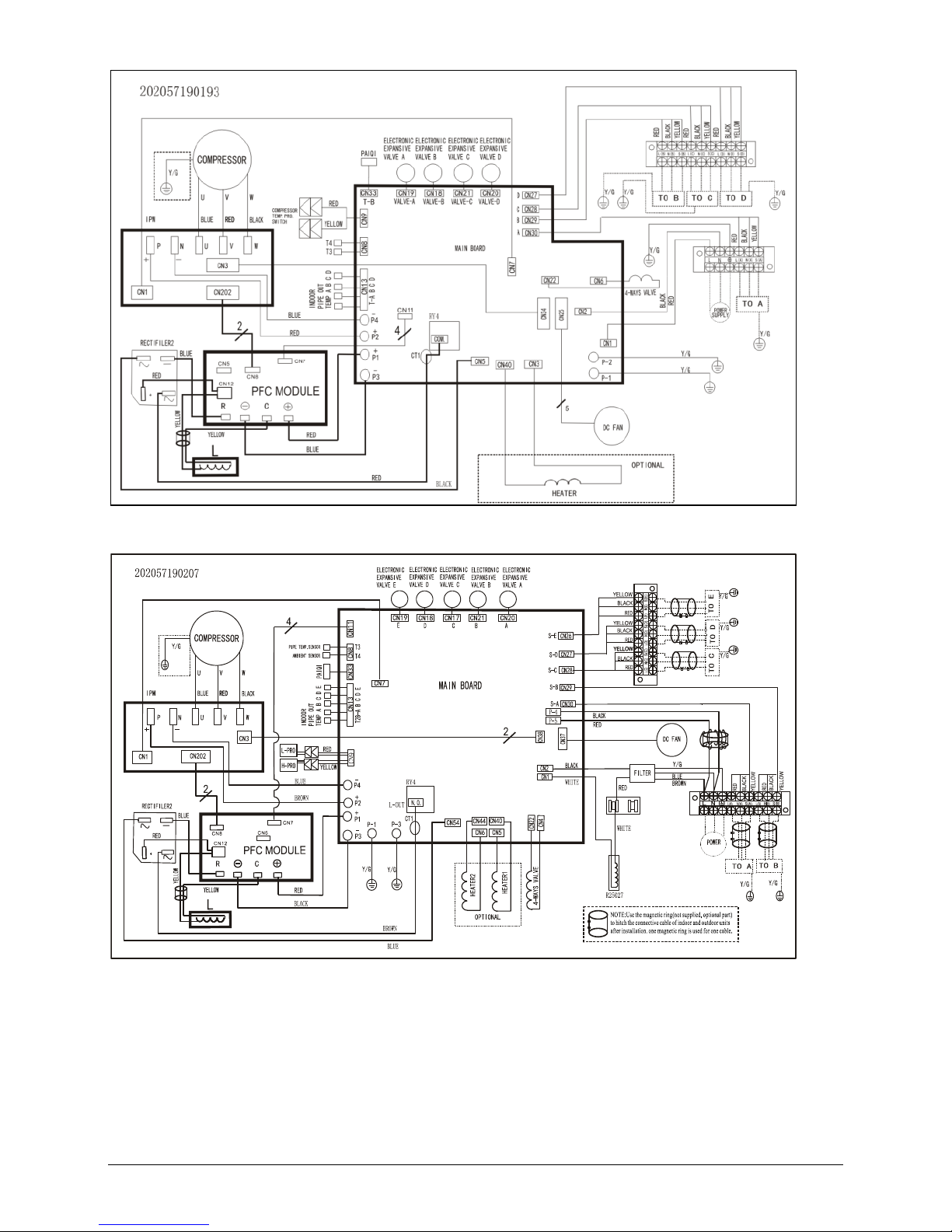
M5OC-36HFN1-Q, M5OD-42HFN1-Q
Page 16
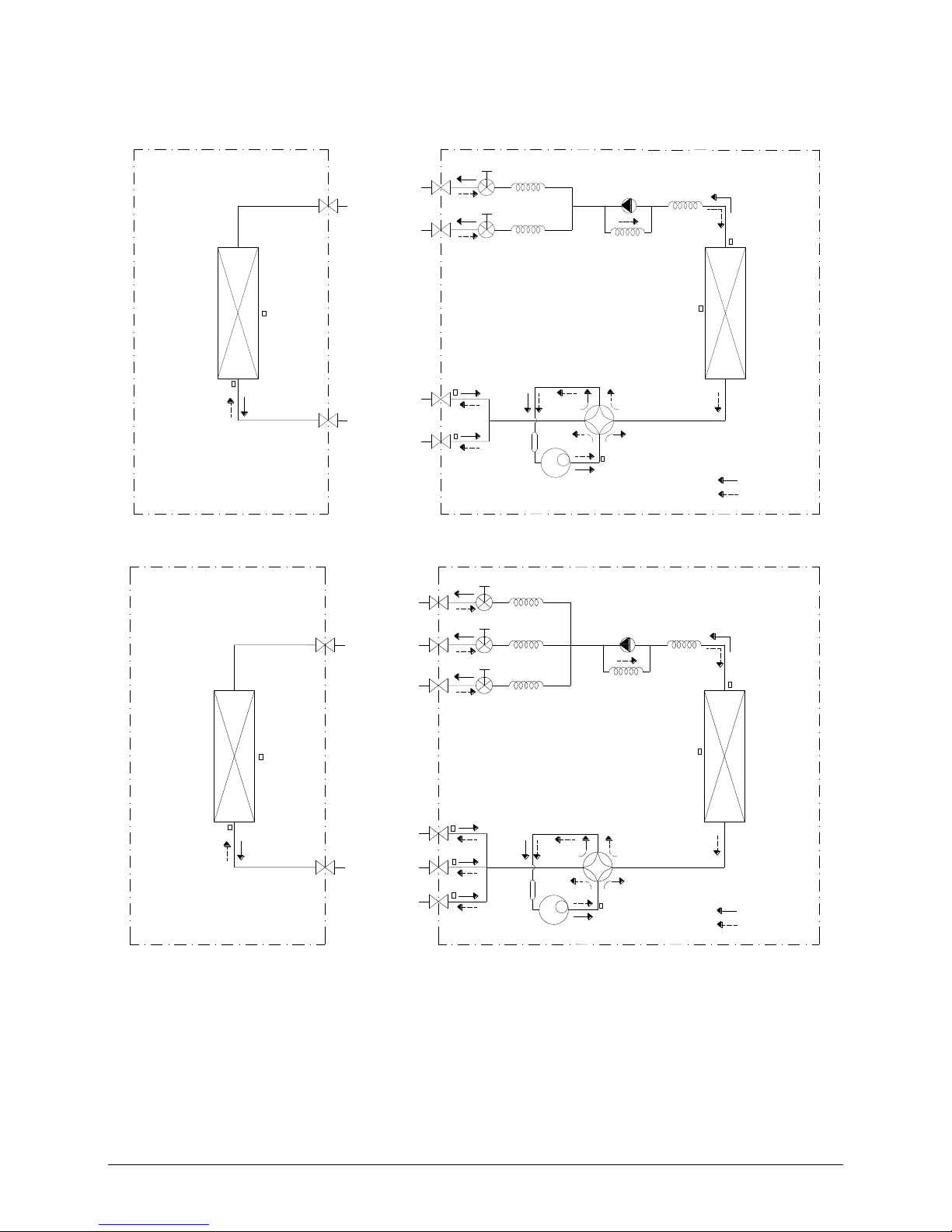
5. Refrigeration Cycle Diagram
5.1 Refrigeration circuit drawing of inverter 1 drive 2 type
LIQUID VALVE A
GAS VALVE A
HEAT
EXCHANGE
(EVAPORATOR)
HEAT
EXCHANGE
(CONDENSER)
Compressor
4-WAY VALVE
COOLING
HEATING
T2 Evaporator
temp. sensor
middle
T1 Room
temp. sensor
T3
Condenser
temp. sensor
T5 Discharge
temp. sensor
T4 Ambient
temp. sensor
INDOOR OUTDOOR
EXV A
CAPILIARY A
CHECK VALVE
CAPILIARY TUBE
EXV B
CAPILIARY B
LIQUID VALVE B
GAS VALVE B
Accumulator
T2B-A Evaporator
temp. sensor outlet
T2B-B
5.2 Refrigeration circuit drawing of inverter 1 drive 3 type
LIQUID VALVE A
GAS VALVE A
HEAT
EXCHANGE
(EVAPORATOR)
HEAT
EXCHANGE
(CONDENSER)
Compressor
4-WAY VALVE
COOLING
HEATING
T2 Evaporator
temp. sensor
middle
T1 Room
temp. sensor
T3
Condenser
temp. sensor
T5 Discharge
temp. sensor
T4 Ambient
temp. sensor
INDOOR OUTDOOR
EXV A
CAPILIARY A
CHECK VALVE
CAPILIARY TUBE
EXV B
CAPILIARY B
LIQUID VALVE B
GAS VALVE B
EXV C
CAPILIARY C
LIQUID VALVE C
GAS VALVE C
Accumulator
T2B-A Evaporator
temp. sensor outlet
T2B-B
T2B-C
Page 17
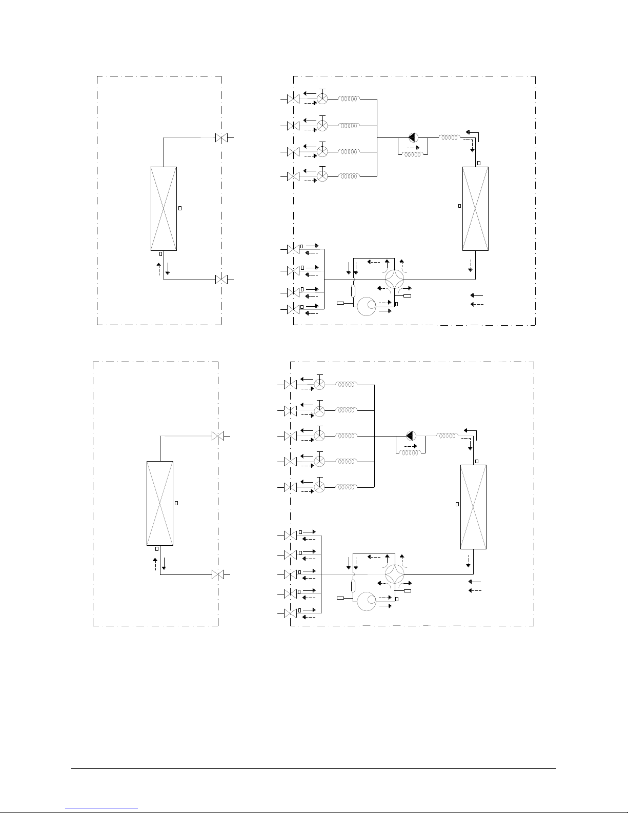
5.3 Refrigeration circuit drawing of inverter 1 drive 4 type
LIQUID VALVE A
GAS VALVE A
HEAT
EXCHANGE
(EVAPORATOR)
HEAT
EXCHANGE
(CONDENSER)
Compressor
4-WAY VALVE
COOLING
HEATING
T2 Evaporator
temp. sensor
middle
T1 Room
temp. sensor
T3
Condenser
temp. sensor
T5 Discharge
temp. sensor
T4 Ambient
temp. sensor
INDOOR OUTDOOR
EXV A
CAPILIARY A
CHECK VALVE
CAPILIARY TUBE
EXV B
CAPILIARY B
LIQUID VALVE B
GAS VALVE B
EXV C
CAPILIARY C
LIQUID VALVE C
GAS VALVE C
EXV D
CAPILIARY D
LIQUID VALVE D
GAS VALVE D
Accumulator
High pressure
switch
Low pressure
switch
T2B-A Evaporator
temp. sensor outlet
T2B-B
T2B-C
T2B-D
5.4 Refrigeration circuit drawing of M5OC-36HFN1-Q
LIQUID VALVE A
GAS VALVE A
HEAT
EXCHANGE
(EVAPORATOR)
HEAT
EXCHANGE
(CONDENSER)
COOLING
HEATING
T2 Evaporator
temp. sensor
middle
T1 Room
temp. sensor
T3
Condenser
temp. sensor
T4 Ambient
temp. sensor
INDOOR OUTDOOR
EXV A
CAPILIARY A
CHECK VALVE
CAPILIARY TUBE
EXV B
CAPILIARY B
LIQUID VALVE B
GAS VALVE B
EXV C
CAPILIARY C
LIQUID VALVE C
GAS VALVE C
EXV D
CAPILIARY D
LIQUID VALVE D
GAS VALVE D
EXV E
CAPILIARY E
LIQUID VALVE E
GAS VALVE E
Compressor
4-WAY VALVE
T5 Discharge
temp. sensor
Accumulator
High pressure
switch
Low pressure
switch
T2B-A Evaporator
temp. sensor outlet
T2B-B
T2B-C
T2B-D
T2B-E
Page 18
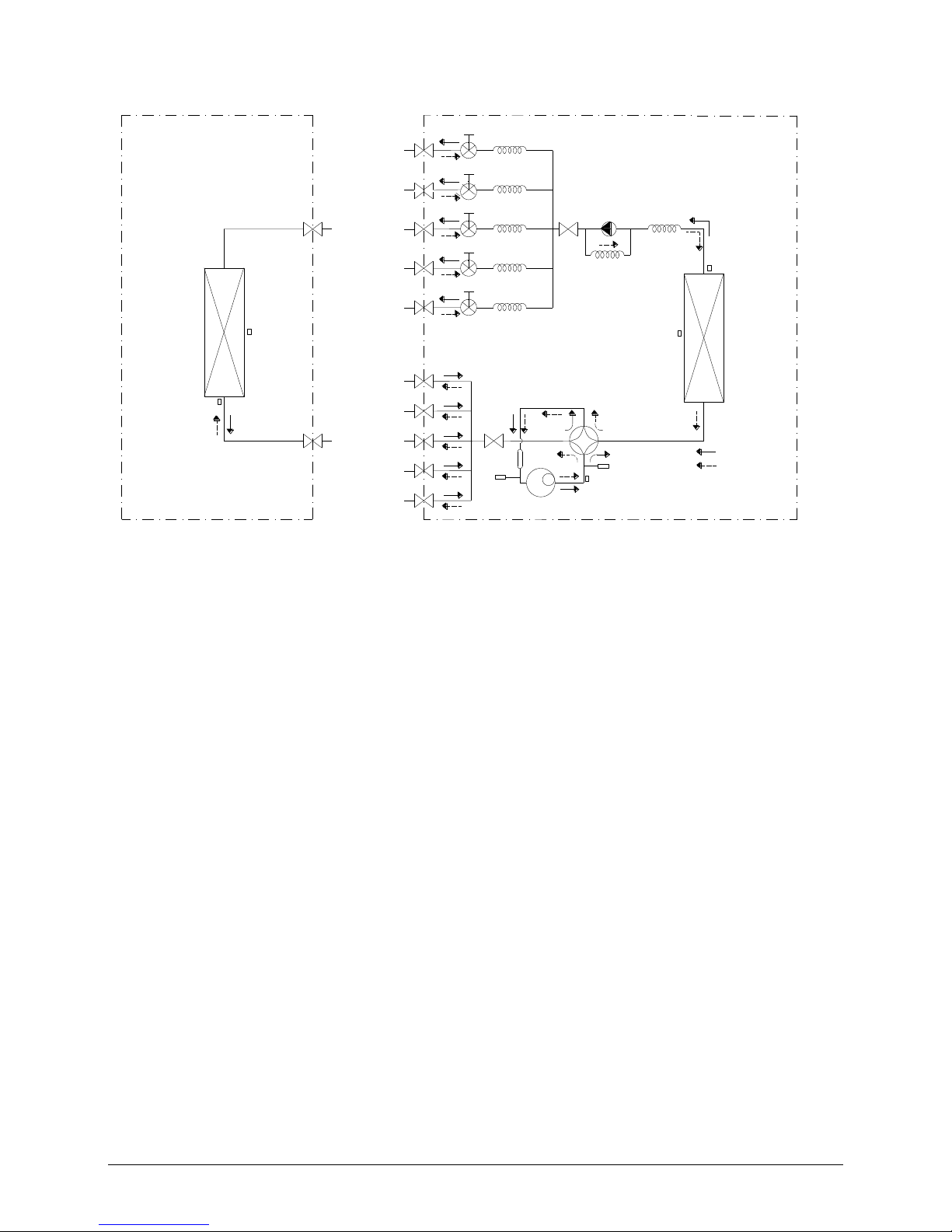
5.5 Refrigeration circuit drawing of M5OD-42HFN1-Q
LIQUID VALVE A
GAS VALVE A
HEAT
EXCHANGE
(EVAPORATOR)
HEAT
EXCHANGE
(CONDENSER)
COOLING
HEATING
T2 Evaporator
temp. sensor
T1 Room
temp. sensor
T3
Condenser
temp. sensor
T4 Ambient
temp. sensor
INDOOR OUTDOOR
EXV A
CAPILIARY A
CHECK VALVE
CAPILIARY TUBE
EXV B
CAPILIARY B
LIQUID VALVE B
GAS VALVE B
EXV C
CAPILIARY C
LIQUID VALVE C
GAS VALVE C
EXV D
CAPILIARY D
LIQUID VALVE D
GAS VALVE D
EXV E
CAPILIARY E
LIQUID VALVE E
GAS VALVE E
Compressor
4-WAY VALVE
T5 Discharge
temp. sensor
Accumulator
High pressure
switch
Low pressure
switch
Page 19
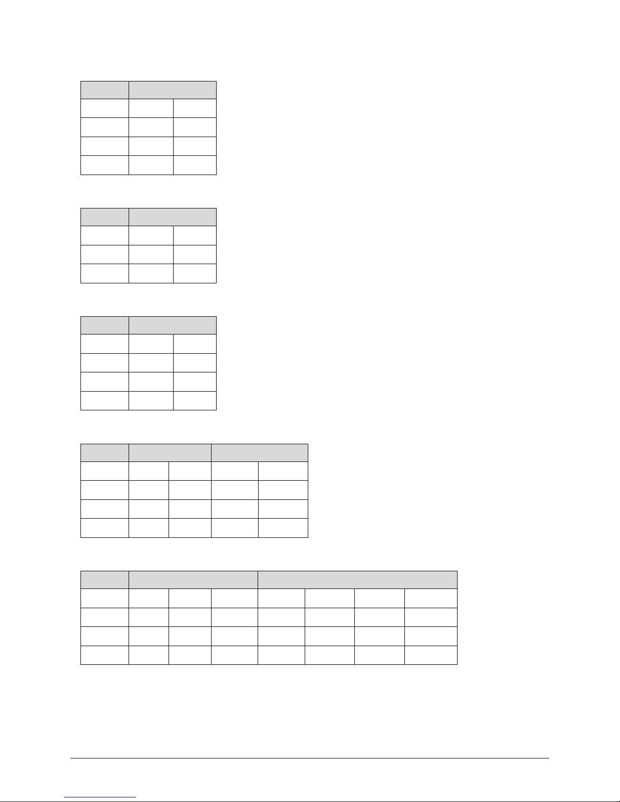
6. Indoor units combination
6.1 Indoor unit combination for M2OD-14HFN1-Q
One unit
Two unit
7
7+7
9+9 9 7+9
9+12
12
7+12 18
6.2 Indoor unit combination for M2OD-16HFN1-Q
One unit
Two unit
7
7+7
9+9 9 7+9
9+12
12
7+12
6.3 Indoor unit combination for M2OD-18HFN1-Q
One unit
Two unit
7
7+7
9+9 9 7+9
9+12
12
7+12
9+18
18
7+18
12+12
6.4 Indoor unit combination for M3OD-21HFN1-Q, M3OD-26HFN1-Q
One unit
Two unit
Three unit
7
7+7
9+9
7+7+7
7+9+12
9
7+9
9+12
7+7+9
9+9+9
12
7+12
9+18
7+7+12
9+9+12
18
7+18
12+12
7+9+9
6.5 Indoor unit combination for M3OD-27HFN1-Q
One unit
Two unit
Three unit
7
7+7
9+9
12+18
7+7+7
7+9+9
7+12+18
9+12+12
9
7+9
9+12
18+18
7+7+9
7+9+12
9+9+9
9+12+18
12
7+12
9+18
7+7+12
7+9+18
9+9+12
12+12+12
18
7+18
12+12
7+7+18
7+12+12
9+9+18
Page 20
6.6 Indoor unit combination for M4OD-28HFN1-Q
6.7 Indoor unit combination for M4OA-36HFN1-Q
6.8 Indoor unit combination for M5OC-36HFN1-Q
One Unit
Two Unit
Three Unit
7
7+7
9+12
7+7+7
7+9+18
9+9+18
12+18+18
9
7+9
9+18
7+7+9
7+12+12
9+12+12
18+18+18
12
7+12
12+12
7+7+12
7+12+18
9+12+18
18
7+18
12+18
7+7+18
7+18+18
9+18+18
9+9
18+18
7+9+9
9+9+9
12+12+12
7+9+12
9+9+12
12+12+18
Four Unit
7+7+7+7
7+7+9+18
7+9+9+18
7+12+18+18
9+9+18+18
7+7+7+9
7+7+12+12
7+9+12+12
9+9+9+9
9+12+12+12
7+7+7+12
7+7+12+18
7+9+12+18
9+9+9+12
9+12+12+18
7+7+7+18
7+7+18+18
7+9+18+18
9+9+9+18
12+12+12+12
7+7+9+9
7+9+9+9
7+12+12+12
9+9+12+12
12+12+12+18
7+7+9+12
7+9+9+12
7+12+12+18
9+9+12+18
Five Unit
7+7+7+7+7
7+7+7+9+18
7+7+9+12+18
7+9+9+12+18
9+9+9+12+12
7+7+7+7+9
7+7+7+12+18
7+7+12+12+18
7+9+12+12+12
9+9+9+12+18
7+7+7+7+12
7+7+7+18+18
7+9+9+9+9
7+9+12+12+18
9+9+12+12+12
One unit
Two unit
Three unit
Four unit
7
7+7
9+9
12+18
7+7+7
7+9+9
9+9+9
7+7+7+7
7+7+9+9
7+9+9+12
9
7+9
9+12
18+18
7+7+9
7+9+12
9+9+12
7+7+7+9
7+7+9+12
7+9+12+12
12
7+12
9+18
7+7+12
7+9+18
9+9+18
7+7+7+12
7+7+12+12
9+9+9+9
18
7+18
12+12
7+7+18
7+12+12
9+12+12
7+7+7+18
7+9+9+9
9+9+9+12
7+12+18
One unit
Two unit
Three unit
Four unit
7
7+7
9+9
12+12
7+7+7
7+12+12
9+12+18
7+7+7+7
7+7+12+12
7+9+12+18
9+9+12+12
9
7+9
9+12
12+18
7+7+9
7+12+18
9+18+18
7+7+7+9
7+7+12+18
7+9+18+18
9+9+12+18
12
7+12
9+18
18+18
7+7+12
7+18+18
12+12+12
7+7+7+12
7+7+18+18
7+12+12+12
9+12+12+12
18
7+18
7+7+18
9+9+9
12+12+18
7+7+7+18
7+9+9+9
7+12+12+18
9+12+12+18
7+9+9
9+9+12
12+18+18
7+7+9+9
7+9+9+12
9+9+9+9
12+12+12+12
7+9+12
9+9+18
7+7+9+12
7+9+9+18
9+9+9+12
12+12+12+18
7+9+18
9+12+12
7+7+9+18
7+9+12+12
9+9+9+18
Page 21

7+7+7+7+18
7+7+9+9+9
7+9+9+9+12
9+9+9+9+9
9+12+12+12+12
7+7+7+9+9
7+7+9+9+12
7+9+9+9+18
9+9+9+9+12
12+12+12+12+12
7+7+7+9+12
7+7+9+9+18
7+9+9+12+12
9+9+9+9+18
6.9 Indoor unit combination for M5OD-42HFN1-Q
One Unit
Two Unit
Three Unit
7
7+7
9+9
7+7+7
7+9+24
9+9+24
12+18+18
9
7+9
9+12
7+7+9
7+12+12
9+12+12
18+18+18
12
7+12
9+18
7+7+12
7+12+18
9+12+18
18
7+18
9+24
7+7+18
7+12+24
9+12+24
24
7+24
12+12
7+7+24
7+18+18
9+18+18
12+18
7+9+9
9+9+9
12+12+12
12+24
7+9+12
9+9+12
12+12+18
18+18
7+9+18
9+9+18
12+12+24
Four Unit
7+7+7+7
7+7+9+24
7+9+9+24
7+12+18+18
9+9+18+18
7+7+7+9
7+7+12+12
7+9+12+12
9+9+9+9
9+12+12+12
7+7+7+12
7+7+12+18
7+9+12+18
9+9+9+12
9+12+12+18
7+7+7+18
7+7+12+24
7+9+12+24
9+9+9+18
12+12+12+12
7+7+7+24
7+7+18+18
7+9+18+18
9+9+9+24
12+12+12+18
7+7+9+9
7+9+9+9
7+12+12+12
9+9+12+12
7+7+9+12
7+9+9+12
7+12+12+18
9+9+12+18
7+7+9+18
7+9+9+18
7+12+12+24
9+9+12+24
Five Unit
7+7+7+7+7
7+7+7+9+18
7+7+9+12+18
7+9+9+12+18
9+9+9+12+12
7+7+7+7+9
7+7+7+12+18
7+7+12+12+18
7+9+12+12+12
9+9+9+12+18
7+7+7+7+12
7+7+7+18+18
7+9+9+9+9
7+9+12+12+18
9+9+12+12+12
7+7+7+7+18
7+7+9+9+9
7+9+9+9+12
9+9+9+9+9
9+12+12+12+12
7+7+7+7+24
7+7+9+9+12
7+9+9+9+18
9+9+9+9+12
12+12+12+12+12
7+7+7+9+9
7+7+9+9+18
7+9+9+12+12
9+9+9+9+18
7+7+7+9+12
Page 22

7. Sound Levels
H
1.0m
Outdoor Unit
Microphone
Note: H= 0.5 × height of outdoor unit
Model
Noise Power dB(A)
Noise level dB(A)
M2OD-14HFN1-Q
63
62
M2OD-16HFN1-Q
65
56
M2OD-18HFN1-Q(W190)
65
56
M2OD-18HFN1-Q(W210)
63
62
M3OD-21HFN1-Q
68
59
M3OD-26HFN1-Q
68
58
M3OD-27HFN1-Q
68
62
M4OD-28HFN1-Q
70
62
M4OA-36HFN1-Q
70
65
M5OC-36HFN1-Q
68
65
M5OD-42HFN1-Q
72
66
Page 23

8. Installation Details
8.1 Wrench torque sheet for installation
Outside diameter
Torque
Additional tightening torque
mm
N.cm
N.cm
Ф6.35
1500(153kgf.cm)
1600(163kgf.cm)
Ф9.52
2500(255kgf.cm)
2600(265kgf.cm)
Ф12.7
3500(357kgf.cm)
3600(367kgf.cm)
8.2 Connecting the cables
The power cord of connect should be selected according to the following specifications sheet.
Rated current of appliance
Nominal cross-sectional area (mm²)
>3 and ≤6
0.75
>6 and ≤10
1
>10 and ≤16
1.5
>16 and ≤25
2.5
The cable size and the current of the fuse or switch are determined by the maximum current indicated on the
nameplate which located on the side panel of the unit. Please refer to the nameplate before selecting the
cable, fuse and switch.
8.3 Pipe length and the elevation
Maximum piping length and height difference
1 drive 2
1 drive 3
1 drive 4
1 drive 5
Max. length for all rooms (m)
30
45
60
75
Max. length for one IU (m)
20
25
30
30
Max. height difference
between IU and OU (m)
OU higher than IU
10
10
10
10
OU lower than IU
15
15
15
15
Max. height difference between IUs (m)
10
10
10
10
Additional refrigerant charge
1 drive 2
1 drive 3
1 drive 4
1 drive 5
Chargeless pipe
length (m)
10
15
20
25
Additional
refrigerant charge
(g)
15 x (length for all
rooms - 10)
15 x (length for all
rooms - 15)
15 x (length for all
rooms - 20)
15 x (length for all
rooms - 25)
Caution:
Page 24

● Refrigerant pipe diameter is different according to indoor unit to be connected. When using the
extension pipe, refer to the tables below.
● When refrigerant pipe diameter is different from that of outdoor unit union (for 18K indoor unit), additional
transfer connector needs to be used on outdoor unit union.
Indoor unit
Extension pipe diameter (mm/inch)
Model
Pipe diameter (mm/inch)
7K9K12K
Liquid
6.35(1/4)
Liquid
6.35(1/4)
Gas
9.52(3/8)
Gas
9.52(3/8)
18K
Liquid
6.35(1/4)
Liquid
6.35(1/4)
Gas
12.7(1/2)
Gas
12.7(1/2)
Outdoor unit union diameter (mm/inch)
Indoor unit A/B/C/D
Liquid
6.35(1/4)
Gas
9.52(3/8)
8.4 Installation for the first time
Air and moisture in the refrigerant system have undesirable effects as below:
● Pressure in the system rises.
● Operating current rises.
● Cooling or heating efficiency drops.
● Moisture in the refrigerant circuit may freeze and block capillary tubing.
● Water may lead to corrosion of parts in the refrigerant system.
Therefore, the indoor units and the pipes between indoor and outdoor units must be leak tested and
evacuated to remove gas and moisture from the system.
Gas leak check (Soap water method):
Apply soap water or a liquid neutral detergent on the indoor unit connections or outdoor unit
connections by a soft brush to check for leakage of the connecting points of the piping. If bubbles come out,
the pipes have leakage.
1. Air purging with vacuum pump
Page 25

1) Completely tighten the flare nuts of the indoor and outdoor units, confirm that both the 2-way and 3-way
valves are set to the closed position.
2) Connect the charge hose with the push pin of handle lo to the 3-way valves gas service port..
3) Connect the charge hose of handle hi connection to the vacuum pump.
4) Fully open the handle Lo of the manifold valve.
5) Operate the vacuum pump to evacuate.
6) Make evacuation for 30 minutes and check whether the compound meter indicates -0.1Mpa. If
the meter does not indicate -0.1Mpa after pumping 30 minutes, it should be pumped 20 minutes more. If the
pressure can’t achieve -0.1Mpa after pumping 50 minutes, please check if there are some leakage points.
Fully close the handle Lo valve of the manifold valve and stop the operation of the vacuum pump. Confirm
that the gauge needle does not move (approximately 5 minutes after turning off the vacuum pump).
7) Turn the flare nut of the 3-way valves about 45° counterclockwise for 6 or 7seconds after the gas
coming out, then tighten the flare nut again. Make sure the pressure display in the pressure indicator is a
little higher than the atmosphere pressure. Then remove the charge hose from the 3 way valve.
8) Fully open the 2 way valve and 3 way valve and securely tighten the cap of the 3 way valve.
2. Air purging by refrigerant
(Indoor unit)
(Liquid side)
(Gas side)
Vacuum
pump
Vacuum
pump
Lo
Hi
Handle Hi
Two-way valve
Close
Manifold valve
Compound meter
Pressure
gauge
-0.1MPa
Handle Lo
Charge hose
Charge hose
(Outdoor unit)
Close
Three-way valve
Page 26

Procedure:
1). Confirm that both the 2-way and 3-way valves are set to the closed position.
2). Connect the charge set and a charging cylinder to the service port of the 3-way valve.
3). Air purging.
Open the valves on the charging cylinder and the charge set. Purge the air by loosening the flare nut on the
2-way valve approximately 45’ for 3 seconds then closing it for 1 minute; repeat 3 times.
After purging the air, use a torque wrench to tighten the flare nut on the 2-way valve.
4). Check the gas leakage.
Check the flare connections for gas leakage.
5). Discharge the refrigerant.
Close the valve on the charging cylinder and discharge the refrigerant by loosening the flare nut on the
2-way valve approximately 45’ until the gauge indicates 0.3 to 0.5 Mpa.
6). Disconnect the charge set and the charging cylinder, and set the 2-way and 3-way valves to the open
position.
Be sure to use a hexagonal wrench to operate the valve stems.
7). Mount the valve stems nuts and the service port cap.
Be sure to use a torque wrench to tighten the service port cap to a torque 18N·m.
Be sure to check the gas leakage.
3. Adding the refrigerant if the pipe length >5m
Page 27

Procedure:
1). Connect the charge hose to the charging cylinder, open the 2-way valve and the 3-way valve.
Connect the charge hose which you disconnected from the vacuum pump to the valve at the bottom of the
cylinder. If the refrigerant is R410A, make the cylinder bottom up to ensure the liquid charge.
2). Purge the air from the charge hose.
Open the valve at the bottom of the cylinder and press the check valve on the charge set to purge the air (be
careful of the liquid refrigerant).
3) Put the charging cylinder onto the electronic scale and record the weight.
4) Operate the air conditioner at the cooling mode.
5) Open the valves (Low side) on the charge set and charge the system with liquid refrigerant.
6).When the electronic scale displays the proper weight (refer to the table), disconnect the charge hose from
the 3-way valve’s service port immediately and turn off the air conditioner before disconnecting the hose.
7). Mount the valve stem caps and the service port
Use torque wrench to tighten the service port cap to a torque of 18N.m.
Be sure to check for gas leakage.
Electronic scale
Page 28

8.5 Adding the refrigerant after running the system for many years
Procedure:
1). Connect the charge hose to the 3-way service port, open the 2-way valve and the 3-way valve.
Connect the charge hose to the valve at the bottom of the cylinder. If the refrigerant is R410A, make the
cylinder bottom up to ensure liquid charge.
2). Purge the air from the charge hose.
Open the valve at the bottom of the cylinder and press the check valve on the charge set to purge the air (be
careful of the liquid refrigerant).
3) Put the charging cylinder onto the electronic scale and record the weight.
4) Operate the air conditioner at the cooling mode.
5) Open the valves (Low side) on the charge set and charge the system with liquid refrigerant.
6).When the electronic scale displays the proper weight (refer to the gauge and the pressure of the low side),
disconnect the charge hose from the 3-way valve’s service port immediately and turn off the air conditioner
before disconnecting the hose.
7). Mount the valve stem caps and the service port
Use torque wrench to tighten the service port cap to a torque of 18N.m.
Be sure to check for gas leakage.
8.6 Re-installation while the indoor unit need to be repaired
1. Collecting the refrigerant into the outdoor unit
Electronic scale
Page 29

Procedure
1). Confirm that both the 2-way and 3-way valves are set to the opened position
Remove the valve stem caps and confirm that the valve stems are in the opened position.
Be sure to use a hexagonal wrench to operate the valve stems.
2). Connect the charge hose with the push pin of handle lo to the 3-way valves gas service port.
3). Air purging of the charge hose.
Open the handle Lo valve of the manifold valve slightly to purge air from the charge hose for 5 seconds and
then close it quickly.
4). Set the 2-way valve to the close position.
5). Operate the air conditioner at the cooling cycle and stop it when the gauge indicates 0.1MPa.
6). Set the 3-way valve to the closed position immediately
Do this quickly so that the gauge ends up indicating 0.3 to 0.5Mpa.
Disconnect the charge set, and tighten the 2-way and 3-way valve’s stem nuts.
Use a torque wrench to tighten the 3-way valves service port cap to a torque of 1.8 kgf.m.
Be sure to check for gas leakage.
2. Air purging by the refrigerant
Page 30

Procedure:
1). Confirm that both the 2-way and 3-way valves are set to the closed position.
2). Connect the charge set and a charging cylinder to the service port of the 3-way valve
Leave the valve on the charging cylinder closed.
3). Air purging.
Open the valves on the charging cylinder and the charge set. Purge the air by loosening the flare nut on the
2-way valve approximately 45’ for 3 seconds then closing it for 1 minute; repeat 3 times.
After purging the air, use a torque wrench to tighten the flare nut on the 2-way valve.
4). Check the gas leakage
Check the flare connections for gas leakage.
5). Discharge the refrigerant.
Close the valve on the charging cylinder and discharge the refrigerant by loosening the flare nut on the
2-way valve approximately 45’ until the gauge indicates 0.3 to 0.5 Mpa.
6). Disconnect the charge set and the charging cylinder, and set the 2-way and 3-way valves to the open
position
Be sure to use a hexagonal wrench to operate the valve stems.
7). Mount the valve stems nuts and the service port cap
Be sure to use a torque wrench to tighten the service port cap to a torque 18N.m.
Be sure to check the gas leakage.
8.7 Re-installation while the outdoor unit need to be repaired
1. Evacuation for the whole system
Page 31

Procedure:
1). Confirm that both the 2-way and 3-way valves are set to the opened position.
2). Connect the vacuum pump to 3-way valve’s service port.
3). Evacuation for approximately one hour. Confirm that the compound meter indicates -0.1Mpa.
4). Close the valve (Low side) on the charge set, turn off the vacuum pump, and confirm that the gauge
needle does not move (approximately 5 minutes after turning off the vacuum pump).
5). Disconnect the charge hose from the vacuum pump.
Page 32

2. Refrigerant charging
Procedure:
1). Connect the charge hose to the charging cylinder, open the 2-way valve and the 3-way valve
Connect the charge hose which you disconnected from the vacuum pump to the valve at the bottom of the
cylinder. If the refrigerant is R410A, make the cylinder bottom up to ensure liquid charge.
2). Purge the air from the charge hose
Open the valve at the bottom of the cylinder and press the check valve on the charge set to purge the air (be
careful of the liquid refrigerant).
3) Put the charging cylinder onto the electronic scale and record the weight.
4). Open the valves (Low side) on the charge set and charge the system with liquid refrigerant
If the system cannot be charge with the specified amount of refrigerant, or can be charged with a little at a
time (approximately 150g each time) , operating the air conditioner in the cooling cycle; however, one time is
not sufficient, wait approximately 1 minute and then repeat the procedure.
5).When the electronic scale displays the proper weight, disconnect the charge hose from the 3-way valve’s
service port immediately
If the system has been charged with liquid refrigerant while operating the air conditioner, turn off the air
conditioner before disconnecting the hose.
6). Mounted the valve stem caps and the service port
Use torque wrench to tighten the service port cap to a torque of 18N.m.
Be sure to check for gas leakage
Page 33

For M5OD-42HFN1-Q.There are one low-pressure centralized valve and one high-pressure centralized
valve, it will be more time saving when vacumm and recycle refrigerant. But refer to the previous instruction
when vacumm and recycle refrigerant.
Page 34

9. Electronic control function
9.1 Abbreviation
T1: Indoor ambient temperature
T2: Coil temperature of indoor heat exchanger middle.
T2B: Coil temperature of indoor heat exchanger outlet.
T3: Coil temperature of outdoor heat exchanger
T4: Outdoor ambient temperature
T5: Compressor discharge temperature
Ts: Setting temperature
9.2 Electric control working environment.
9.2.1 Input voltage: 198V~264V.
9.2.2 Input power frequency:50Hz.
9.2.3 Indoor fan normal working amp. is less than 1A.
9.2.4 Outdoor fan. Normal working amp. is less than 1.5A.
9.2.5 Four-way valve normal working amp. is less than 1A.
9.3 Outdoor unit’s digital display tube
There is a digital display tube in outdoor PCB.
Digital display tube display function
In standby , the LED displays “- -”
In compressor operation, the LED display the running frequency,
In defrosting mode, The LED displays “dF” or alternative displays between running frequency and
“dF”(each displays 0.5s)
In compressor pre-heating, The LED displays “PH” or alternative displays between running frequency
and “PH”(each displays 0.5s)
During the oil return process, The LED displays “RO” or alternative displays between running
frequency and “RO”(each displays 0.5s)
In low ambient cooling mode, the LED displays “LC” or alternative displays between running
frequency and “LC”(each displays 0.5s)
In forced cooling mode, the LED displays “FC” or alternative displays between running frequency and
“FC”(each displays 0.5s)
When PFC module protection occurs three times within 15 minutes, the LED displays “E6” or
alternative displays between running frequency and “E6”(each displays 0.5s)
In protection or malfunction, the LED displays error code or protection code.
Page 35

9.4 Outdoor unit point check function
There is a check switch in outdoor PCB.
Press the switch N times it will display the content corresponding to No. N. After getting into the check function, it
will display No. N with 1.5s, meanwhile the low bit decimal of digit display flashing, indicated to get into the check
function display. After 1.5s, it will display the content corresponding to No. N.
the digital display tube will display the follow procedure when push SW1 each time.
Display
Remark
0
Normal display
Display running frequency, running state or malfunction code
1
No. of indoor units in good connection
Actual data
2
Outdoor unit running mode code
Off:0,Fan only 1, Cooling:2, Heating:3, Forced cooling:4
3
A indoor unit capacity
The capacity unit is horse power. If the indoor unit is not connected,
the digital display tube will show: “――”
(7K:0.8HP, 9K:1HP,12K:1.2HP,18K:1.5HP)
4
B indoor unit capacity
5
C indoor unit capacity
6
D indoor unit capacity
7
E indoor unit capacity
8
A Indoor unit capacity demand code
Norm value*HP
(7K:0.8HP, 9K:1HP,12K:1.2HP,18K:1.5HP)
9
B Indoor unit capacity demand code
10
C Indoor unit capacity demand code
11
D Indoor unit capacity demand code
12
E Indoor unit capacity demand code
13
Total indoor units amendatory capacity
demand code
Forced cooling:7
14
The frequency corresponding to the total
indoor units amendatory capacity demand
15
The frequency after the frequency limit
16
The frequency sending to compressor
control chip
17
A indoor unit evaporator outlet temp.(T2BA)
If the temp. is lower than -9 degree, the digital display tube will show
“-9”.If the temp. is higher than 70 degree, the digital display tube will
show “70”. If the indoor unit is not connected, the digital display tube
will show: “――”
18
B indoor unit evaporator outlet temp.(T2BB)
19
C indoor unit evaporator outlet temp.(T2BC)
20
D indoor unit evaporator outlet temp.(T2BD)
21
E indoor unit evaporator outlet temp.(T2BE)
22
A indoor unit room temp.(T1A)
If the temp. is lower than 0 degree, the digital display tube will show
“0”.If the temp. is higher than 50 degree, the digital display tube will
show “50”. If the indoor unit is not connected, the digital display tube
will show: “――”
23
B indoor unit room temp.(T1B)
24
C indoor unit room temp.(T1C)
25
D indoor unit room temp.(T1D)
26
E indoor unit room temp.(T1E)
27
A indoor unit evaporator temp.(T2A)
If the temp. is lower than -9 degree, the digital display tube will show
“-9”.If the temp. is higher than 70 degree, the digital display tube will
show “70”. If the indoor unit is not connected, the digital display tube
will show: “――”
28
B indoor unit evaporator temp.(T2B)
29
C indoor unit evaporator temp.(T2C)
30
D indoor unit evaporator temp.(T2D)
31
E indoor unit evaporator temp.(T2E)
32
Condenser pipe temp.(T3)
33
Outdoor ambient temp.(T4)
34
Compressor discharge temp.(T5)
The display value is between 30~129 degree. If the temp. is lower
than 30 degree, the digital display tube will show “30”.If the temp. is
higher than 99 degree, the digital display tube will show single digit
and tens digit. For example, the digital display tube show “0.5”,it
means the compressor discharge temp. is 105 degree.)
35
AD value of current
The display value is hex number.
Page 36

36
AD value of voltage
For example ,the digital display tube show “Cd”, it means AD value is
205.
37
EXV open angle for A indoor unit
Actual data/4.
If the value is higher than 99, the digital display tube will show single
digit and tens digit.
For example ,the digital display tube show “2.0”,it means the EXV
open angle is 120×4=480p.)
38
EXV open angle for B indoor unit
39
EXV open angle for C indoor unit
40
EXV open angle for D indoor unit
41
EXV open angle for E indoor unit
42
Frequency limit symbol
Bit7
Frequency limit caused by IGBT
radiator
The display value
is hex number. For
example, the
digital display tube
show 2A,then
Bit5=1, Bit3=1,
Bit1=1.
It means
frequency limit
caused by T4,T3
and current.
Bit6
Frequency limit caused by PFC
Bit5
Frequency limit caused by T4.
Bit4
Frequency limit caused by T2.
Bit3
Frequency limit caused by T3.
Bit2
Frequency limit caused by T5.
Bit1
Frequency limit caused by current
Bit0
Frequency limit caused by voltage
43
Average value of T2
(Sum T2 value of all indoor units)/( number of indoor units in good
connection)
44
Outdoor unit fan motor state
Off:0, High speed:1, Med speed:2, Low speed:3 Breeze:4, Super
breeze:5
45
The last error or protection code
00 means no malfunction and protection
The following items from 9.4.1 to 9.4.5 are for the explanation of the point check functions.
9.4.1 Frequency of compressor:
Display
Frequency of compressor (Hz)
30
30
--
Stand by
60
60
9.4.2 Running mode:
Display
Corresponding mode
0
Off 1 Fan only
2
Cooling mode
3
Heating mode
4
Forced cooling
9.4.3 Capacity demand:
Cooling mode
T1 Ts
3
1
1
e
c
a
4
2
0
2
3
0
1
f
d
b
Page 37

Capacity area
a b c d e
f
Norm value (N)
3 2 1.5 1 0.5
0
Heating mode
T1 Ts
4
0
a
3
1
-1
3
1
2
0
b
c
d
e
f
2
Capacity area
a b c d e
f
Norm value (N)
3 2 1.5 1 0.5
0
9.4.4 Number of indoor unit
Display
Number of indoor unit
1 1 2
2
3 3 4
4
5
5
9.4.5 Opening degree of electronic expansion valve:
Actual opening degree equals the display data times 4
Page 38

9.5 Protection
9.5.1 Three minutes delay at restart for compressor.
9.5.2 Temperature protection of compressor discharge.
When the compressor discharge temp. is getting higher, the running frequency will be limited as below rules:
----If 102℃<T5<115℃, decrease the frequency to the lower level every 2 minutes till to F1.
---If T5>115℃ for 10 seconds, the compressor will stop and restart till T5<90℃.
9.4.3 Low voltage protection
VOLT_RST1_ADD
VOLTAGE
No limit
VOLT_LTM1_ADD
VOLT_RST2_ADD
VOLT_LTM2_ADD
VOLT_LTM_FREQ1_ADD
VOLT_LTM_FREQ2_ADD
Note: if the low voltage protection occurs and not resumes within 3min, it will keep the protection always
after restart the machine.
9.5.4 Compressor current limit protection
If the compressor current exceeds the current limit value for 10 seconds, the compressor frequency will be
limited as below table.
Cooling mode:
Current frequency(Hz)
Current limit value(A)
Frequency limit
COOL_F16
ICOOLLMT12
Decrease the frequency to COOL_F4 and run at COOL_F4 for
3 minutes.
After that, the frequency will be adjusted according to the
capacity demand and rise to the upper level every 3 minutes
(When the frequency>COOL_F4 via capacity demand).
COOL_F15
ICOOLLMT11
COOL_F14
ICOOLLMT10
COOL_F13
ICOOLLMT9
COOL_F12
ICOOLLMT8
COOL_F11
ICOOLLMT7
COOL_F10
ICOOLLMT6
COOL_F9
ICOOLLMT5
COOL_F8
ICOOLLMT4
COOL_F7
ICOOLLMT3
COOL_F6
ICOOLLMT2
COOL_F5
ICOOLLMT1
If the current frequency is lower than COOL_F4, the frequency will not be limited.
After 10s of the compressor start, if the current>ICOOL, the AC will display the failure for 30 seconds and stop. The AC
will restart 3 minutes later.
Heating mode:
Current frequency(Hz)
Current limit value(A)
Frequency limit
HEAT_F16
IHEATLMT12
Decrease the frequency to HEAT_F4 and run at HEAT_F4 for
Page 39

HEAT_F15
IHEATLMT11
3 minutes.
After that, the frequency will be adjusted according to the
capacity demand and rise to the upper level every 3 minutes
(When the frequency>Heat_F4 via capacity demand).
HEAT_F14
IHEATLMT10
HEAT_F13
IHEATLMT9
HEAT_F12
IHEATLMT8
HEAT_F11
IHEATLMT7
HEAT_F10
IHEATLMT6
HEAT_F9
IHEATLMT5
HEAT_F8
IHEATLMT4
HEAT_F7
IHEATLMT3
HEAT_F6
IHEATLMT2
HEAT_F5
IHEATLMT1
If the current frequency is lower than HEAT_F4, the frequency will not be limited.
After 10s of the compressor start, if the current>IHEAT, the AC will display the failure for 30 seconds and stop. The AC
will restart 3 minutes later.
9.5.5 Indoor / outdoor units communication protection
If the indoor units can not receive the feedback signal from the outdoor units for 2 minutes, the AC will stop
and display the failure.
9.5.6 High condenser coil temp. protection.
When T3>65℃ for 3 seconds, the compressor will stop while the indoor fan and outdoor fan will continue.
When T3<52℃, the protection will release and the compressor will restart after 3 minutes.
9.5.7 Outdoor unit anti-freezing protection
For other models: When T2B<0℃ for 250 seconds, the indoor unit capacity demand will be zero and resume
to normal when T2B>10℃.
For M2OD-16HFN1-Q,M2OD-18HFN1-Q,M5OD-42HFN1-Q: When T2<4℃ for 250 seconds or T2<0℃,
the indoor unit capacity demand will be zero and resume to normal when T2>8℃ and the time of protection
is no less than 3 minutes.
9.5.8 Oil return
Running rules:
1. If the compressor frequency keeps lower than RET_OIL_FREQ1_ADD for RET_OIL_TIME1_ADD, the
AC will rise the frequency to RET_OIL_FREQ2_ADD for RET_OIL_TIME2_ADD and then resume to
former frequency.
2. The EXV will keep 300p while the indoor units will keep the current running mode.
If the outdoor ambient is higher than TempT4HeatLimit_ADD during the oil return, the AC quit oil return.
Page 40

10. Troubleshooting
10.1 Indoor unit error code explanation:
PREMIER series +OASIS series+9A series +R series +12F series +Aurora series:
Display
Operation lamp flash times
Timer lamp
Failure
E0 1 X
Indoor EEPROM malfunction
E1 2 X
Indoor / outdoor units communication error
E3 4 X
Indoor fan speed has been out of control
E4 5 X
Open or short circuit of T1 temperature sensor
E5 6 X
Open or short circuit of T2 temperature sensor
F1 2 O
Open or short circuit of T4 temperature sensor
F2 3 O
Open or short circuit of T3 temperature sensor
F3 4 O
Open or short circuit of T5 temperature sensor
F4 5 O
Outdoor EEPROM parameter error
F5 6 O
Outdoor fan speed out of control
F6 7 O
Open or short circuit of T2B temperature sensor
P0
1
☆
IPM module protection
P1
2
☆
Voltage protection
P4 5 ☆
Inverter compressor drive protection
P5
6
☆
Mode conflict
P6
7
☆
Low pressure protection(Just matching with
M4OA-36HFN1-Q,M4OD-28HFN1-Q,M5OC-36HF
N1-Q, M5OD-42HFN1-Q)
O (light) X (off) ☆ (flash)
Light Commercial series(Except Console)
NO.
MALFUNCTION
RUN
Timer
DEF
Alarm
DISPLAY
DIGITAL TUBE
1
Open or short circuit of T1 temperature sensor
☆
X X X
E0
2
Open or short circuit of T2 temperature sensor
X
X ☆ X
E1
3
Indoor / outdoor units communication error
X ☆ X
X
E2
4
Full-water malfunction
X X X ☆ E3
5
Indoor EEPROM malfunction
☆
☆
X
X
E4
6
IPM module protection
☆
X X O
E5
7
Open or short circuit of T3 or T4 temperature sensor or
Outdoor EEPROM malfunction
☆
O
X X E6
8
Outdoor fan speed has been out of control
☆
O
☆
X
E7
9
Indoor fan speed has been out of control
☆
O
O
X
F5
10
Voltage protection
☆
O X O
P0
11
Outdoor unit over-current protection
☆ ☆ ☆
X
P2
12
Inverter compressor drive protection
☆
◎
X
X
P4
13
Mode conflict
☆
X O O
P5
☆ Flash(at 2.5Hz) ◎ Flash(at 0.5Hz) O light X(off)
Note: Digital display is only available for A5 duct type.
Page 41

For Console
NO.
Malfunction
Running lamp
Timer lamp
Defrosting lamp
1
Open or short circuit of T1 temperature sensor
☆
X
X
2
Open or short circuit of T2 temperature sensor
X X ☆
3
Communication malfunction between indoor and outdoor
units.
X ☆ X
4
Outdoor fan speed has been out of control
X ☆ O
5
Indoor EEPROM malfunction
☆
☆
X
6
IPM module protection
☆ X ☆
7
Open or short circuit of T3 or T4 temperature sensor or
Outdoor unit EEPROM parameter error
☆ ☆ ☆
8
Voltage protection
☆ ☆ O
9
Inverter compressor drive protection
☆
◎
X
10
Indoor fan speed has been out of control.
☆ O ☆
11
Mode conflict
☆ X O
O(light) X(off) ☆(flash at 5Hz) ◎(flash at 0.5Hz)
Page 42

10.2 Outdoor unit error code explanation:
Display
LED STATUS
E0
Outdoor EEPROM malfunction
E2
Indoor / outdoor units communication error
E3
Communication malfunction between IPM board and outdoor main board
E4
Open or short circuit of outdoor unit temperature sensor
E5
Voltage protection
E8
Outdoor fan speed has been out of control
F1
No A Indoor unit coil outlet temperature sensor or connector of sensor is defective
F2
No B Indoor unit coil outlet temperature sensor or connector of sensor is defective
F3
No C Indoor unit coil outlet temperature sensor or connector of sensor is defective
F4
No D Indoor unit coil outlet temperature sensor or connector of sensor is defective
F5
No E Indoor unit coil outlet temperature sensor or connector of sensor is defective
P1
High pressure protection (For M4OA-36HFN1-Q, M4OD-28HFN1-Q, M5OC-36HFN1-Q,
M5OD-42HFN1-Q)
P2
Low pressure protection (For M4OA-36HFN1-Q, M4OD-28HFN1-Q, M5OC-36HFN1-Q,
M5OD-42HFN1-Q)
P3
Current protection of compressor
P4
Temperature protection of compressor discharge
P5
High temperature protection of condenser
P6
IPM module protection
Note: Once these error codes display, they will disappear in at least 30 seconds if the unit come back to
normal.(Except E3&E4)
Page 43

10.3 Trouble shooting
10.3.1 For the indoor unit
10.3.1.1 Indoor EEPROM malfunction
Yes
Replace the indoor main PCB
Power off, then restart the
unit 2 minutes later
EEPROM: An electrically erasable programmable read-only memory whose contents can be erased and
reprogrammed using a pulsed voltage.
Page 44

10.3.1.2 Indoor / outdoor units communication error
Indoor / outdoor units communication error
Start: Power off , then Power on the
A/C by the Breaker. (reconnect the
power wire). Is it still displaying the
error code?
Yes
No
Replacee outdoor unit PCB assembly(include
wiring) totally
Check wiring on the outdoor and indoor
terminal follow the wiring diagram. Is all
connecting correctly?
Yes
No
Measure Vs, is it moving
alternately between positive value
and negative value? (Vs is the
voltage between S and N). Refer
PIC 1
Turn on all indoor unit by remote
controller. Is all indoor unit display
Turn off the all indoor units. Is IPM
power LED or operating LED lamp
On? Refer PIC2
Yes
A: Is all the wiring between
terminal and Indoor PCB
connect ok?
No
Yes
A
No
Reconnect the wiring
Is indoor units number correct? Check
on the outdoor check point . (2 for dual
zone, 3 for tri zone, 4 for qua zone,5 for
qui zone). Refer PIC 4.
Yes
No first time
Yes
Yes
Replace the Indoor PCB
Power on by remote
controller, IIs it still
displaying the error code
after 3 minutes?
Trouble is solved
No second time
No
Yes
Reconnect the wiring
No
Replace IPM board or
the outdoor main PCB
No
Is the reactor connecting
well?
No Reconnect the wiring
Replace the outdoor main PCB
Yes
No
Is main board“ ”
lamp on? Refer PIC 3.
Page 45

Pic 2:IPM or outdoor main PCB (For
M2OD-14HFN1-Q/M2OD-18HFN1-Q
(W210) / M4OD-28HFN1-Q/tri-zone)
Self-Check
Power,
Operating
Self-Check
Operating
Pic 2: IPM or outdoor main PCB (For
M2OD-16HFN1-Q /
M2OD-18HFN1-Q(W190)/M4OA-36H
FN1-Q/ qui-zone)
Pic 1: check the voltage of N to S
(Vs), is it moving alternately
between positive value and negative
value?
Page 46

.
PIC3 :Main board LED when power on and unit
standby.
PIC 4: check point button,
Press 1 time for check how many indoor units are
connected
Page 47

10.3.1.3 indoor unit fan speed has been out of control
Power off, then restart the
unit 2 minutes later. Is it still
displaying the error code?
Power off, then restart the
unit 2 minutes later. Is it still
displaying the error code?
Sh u t off t h e powe r supply ,
rotate the fan by hand. Does
it rotate properly?
Sh u t off t h e powe r supply ,
rotate the fan by hand. Does
it rotate properly?
The unit operates normally.
The unit operates normally.
Find out the cause and
have it solved. For
example, whether the fan
is blocked or the screws
which fix the fan are
tighten.
Find out the cause and
have it solved. For
example, whether the fan
is blocked or the screws
which fix the fan are
tighten.
Check the wiring of fan
motor. Are all the
connections good?
Check the wiring of fan
motor. Are all the
connections good?
No
Yes
No
Correct the connections.
Correct the connections.No
Replace the fan motor
Replace the fan motor
Yes
Yes
Replace the main PCB
Replace the main PCBNo
Check whether the main PCB
is normal through index 1?
Check whether the main PCB
is normal through index 1?
Yes
No
Index 1:
1: Indoor AC fan motor
Power on and set the unit running in fan mode at high fan speed. After running for 15 seconds, measure the
voltage of pin1 and pin2. If the value of the voltage is less than 100V(208~240V power supply)or 50V(115V
power supply), the PCB must have problems and need to be replaced.
2. Indoor DC fan motor(control chip is inside fan motor)
Power on and when the unit is in standby, measure the voltage of pin1-pin3, pin4-pin3 in fan motor
connector. If the value of the voltage is not in the range showing in below table, the PCB must have
problems and need to be replaced.
For other models:
Page 48

For console:
5
4
6
3
2
1
DC motor voltage input and output
For split type:
NO.
Color
Signal
Voltage
1
Red
Vs/Vm
280V~380V
2
---
---
---
3
Black
GND
0V
4
White
Vcc
14-17.5V
5
Yellow
Vsp
0~5.6V
6
Blue
FG
14-17.5V
For other types:
NO.
Color
Signal
Voltage
1
Red
Vs/Vm
192V~380V
2
---
---
---
3
Black
GND
0V
4
White
Vcc
13.5-16.5V
5
Yellow
Vsp
0~6.5V
6
Blue
FG
13.5-16.5V
Page 49

10.3.1.4 Open or short circuit of temperature sensor.
Check the connections
between temperature
sensor and PCB. Are the
connections good?
Check the connections
between temperature
sensor and PCB. Are the
connections good?
Correct the connections.
Correct the connections.No
Yes
No
Replace the sensor.
Replace the sensor.
Replace the indoor PCB
Replace the indoor PCB
Measure the resistance value
of the sensor via Appendix 1
Measure the resistance value
of the sensor via Appendix 1
Is it normal?
Is it normal?
Yes
10.3.1.6 Full-water malfunction
If the water-level switch
is inserted well?
If the water-level switch
is inserted well?
No
Insert the water-level switch well
Insert the water-level switch well
If the water-level switch
is broken?
If the water-level switch
is broken?
Yes
Replace the water-level switch
Replace the water-level switch
Replace the water pump, If
malfunction is still not
solved
Replace the water pump, If
malfunction is still not
solved
Yes
No
Yes
Replace the indoor main PCB
Replace the indoor main PCB
Power off, then restart the unit 2 minutes
later. Is it still displaying the error code?
Power off, then restart the unit 2 minutes
later. Is it still displaying the error code?
Yes
Page 50

10.3.2 For the outdoor unit
10.3.2 1 Outdoor EEPROM malfunction(ODU E0)
Yes
Replace the outdoor main PCB
Replace the outdoor main PCB
Power off, then restart the
unit 2 minutes later
Power off, then restart the
unit 2 minutes later
EEPROM: An electrically erasable programmable read-only memory whose contents can be erased and
reprogrammed using a pulsed voltage.
Page 51

10.3.2.2 Communication malfunction between IPM board and outdoor main board(ODU E3)
Communication malfunction between
IPM board and outdoor main board
Is there at least one LED in
the IPM board light?
Check the signal wire between
the IPM board and the main
board, is it connected good?
Reconnect and retry. Is
error still display?
Replace IPM board, and
then check whether the
system can run normally
Replace the electric control
box
No
No
No
No
Yes
Trouble is solved
No
Yes
Replace outdoor main
board, and then check
whether the system can run
normally
No
Yes
Yes
E3 display
Page 52

10.3.2.3 Voltage protection(ODU E5)
Voltage protection
Check the voltage of
outdoor unit power supply,
whether the voltage
between L(L1) and N (L2) is
about 220~240VAC
Check the power supply
Check whether the voltage
of IPM board P and N is
normal? DC277-356V for
18-27KBtu/h; DC277-410V
for 36-42KBtu/h
Replace bridge rectifiers,
and then check whether the
system can run normally
Replace IPM board, and
then check whether the
system can run normally
Replace outdoor main board
Yes
No
No
No
No
Yes
Trouble is solved
Yes
Yes
Page 53

10.3.2.4 Outdoor unit fan speed has been out of control (E8)
Power off, then restart the
unit 2 minutes later. Is it still
displaying the error code?
Power off, then restart the
unit 2 minutes later. Is it still
displaying the error code?
Sh u t off t h e powe r supply ,
rotate the fan by hand. Does
it rotate properly?
Sh u t off t h e powe r supply ,
rotate the fan by hand. Does
it rotate properly?
The unit operates normally.
The unit operates normally.
Find out the cause and
have it solved. For
example, whether the fan
is blocked or the screws
which fix the fan are
tighten.
Find out the cause and
have it solved. For
example, whether the fan
is blocked or the screws
which fix the fan are
tighten.
Check the wiring of fan
motor. Are all the
connections good?
Check the wiring of fan
motor. Are all the
connections good?
No
Yes
No
Correct the connections.
Correct the connections.No
Replace the fan motor
Replace the fan motor
Yes
Yes
Replace the main PCB
Replace the main PCBNo
Check whether the main PCB
is normal through index 1?
Check whether the main PCB
is normal through index 1?
Yes
No
Index 1:
1. Outdoor DC fan motor(control chip is inside fan motor)
Power on and when the unit is in standby, measure the voltage of pin1-pin3, pin4-pin3 in fan motor
connector. If the value of the voltage is not in the range showing in below table, the PCB must have
problems and need to be replaced.
DC motor voltage input and output
NO.
Color
Signal
Voltage
1
Red
Vs/Vm
140V~380V
2
---
---
--- 3 Black
GND
0V
4
White
Vcc
13.5-16.5V
5
Yellow
Vsp
0~6.5V
6
Blue
FG
15V
Page 54

10.3.2.5 High pressure protection (ODU P1) (For M4OA-36HFN1-Q, M4OD-28HFN1-Q,
M5OC-36HFN1-Q, M5OD-42HFN1-Q)
Whether the wiring
between the high pressure
switch and main control
board is connected well or
correctly
Whether the wiring
between the high pressure
switch and main control
board is connected well or
correctly
Method: Disconnect the plug.
Measure the resistance of the
high pressure protector, if
the protector is normal the
value is o,
Method: Disconnect the plug.
Measure the resistance of the
high pressure protector, if
the protector is normal the
value is o,
Yes
Yes
Connect it well
Connect it wellNo
Replace high pressure protector
Replace high pressure protectorNo
Whether the high
pressure protector
is broken
Whether the high
pressure protector
is broken
Check whether the outdoor
ambient temperature is
higher than 50℃
Check whether the outdoor
ambient temperature is
higher than 50℃
No
Stop the unit
Stop the unit Yes
Check if the outdoor unit
ventilation is good
Check if the outdoor unit
ventilation is good
Yes
Make the outdoor unit ventilate well
Make the outdoor unit ventilate well
Check whether the heat
exchanger is dirty
Check whether the heat
exchanger is dirty
No
Clean the heat exchanger
Clean the heat exchangerYes
Check whether the refrigerant
system is ok
Check whether the refrigerant
system is ok
Replace outdoor main
board
Replace outdoor main
board
No
High pressure protection
High pressure protection
Check if the outdoor fan runs
properly
Check if the outdoor fan runs
properly
please refer to the solution of fan
speed has been out of control
malfunction . Find out the cause and
have it solved.
please refer to the solution of fan
speed has been out of control
malfunction . Find out the cause and
have it solved.
No
Yes
NO
Page 55

10.3.2.6 Low pressure protection (ODU P2) (For M4OA-36HFN1-Q, M4OD-28HFN1-Q,
M5OC-36HFN1-Q, M5OD-42HFN1-Q)
Low pressure protection
Low pressure protection
Whether the wiring
between the low pressure
protector and main control
board is connected well or
correctly
Whether the wiring
between the low pressure
protector and main control
board is connected well or
correctly
Method: Disconnect the plug.
Measure the resistance of the
low pressure protector. If the
protector is normal the value is
o
Method: Disconnect the plug.
Measure the resistance of the
low pressure protector. If the
protector is normal the value is
o
Yes
Yes
Connect it well
Connect it well
Replace outdoor main board
Replace outdoor main board
No
Replace low pressure protector
Replace low pressure protector
No
Whether the low
pressure protector
is broken
Whether the low
pressure protector
is broken
Check whether the outdoor
ambient temperature is too
low
Check whether the outdoor
ambient temperature is too
low
No
Stop the unit
Stop the unit Yes
Open fully valve core of
high pressure valve
Open fully valve core of
high pressure valve
No
Check whether valve core
of high pressure valve is
opened
Check whether valve core
of high pressure valve is
opened
Check if the indoor fan runs
properly in cooling mode
Check if the indoor fan runs
properly in cooling mode
please refer to the solution of fan
speed has been out of control
malfunction. Find out the cause and
have it solved.
please refer to the solution of fan
speed has been out of control
malfunction. Find out the cause and
have it solved.
No
Yes
Yes
No
Check whether the refrigerant
system is ok
Check whether the refrigerant
system is ok
Refrigerant is not enough add the
refrigerant
Refrigerant is not enough add the
refrigerant
No
Page 56

10.3.2.7 Current protection of compressor (ODU P3)
Current protection of compressor
Judge 1: Check whether the
input current of the power
supply wire is higher than max
protection current value
Yes
Replace the electric control box
Check whether
the refrigerant
system is ok
Judge 2: Check whether the
outdoor ambient
temperature is higher than
50℃
No
Stop the unitYes
Judge 3: Check whether the
outdoor unit is bad ventilation
No
Make the outdoor unit ventilate wellYes
Judge 5: The refrigerant
pipe is blocked
No
Let the refrigerant out, then use the high
pressure nitrogen or refrigerant to blow pipe,
vacuumize and charge the refrigerant again
Yes
Judge 4: Check whether the
heat exchanger is dirty
No
Clean the heat exchanger
Yes
Yes
Replace outdoor main
board,and check whether
the system can run normally
No
Yes
Trouble is solved
Model
M2OD-16H
FN1-Q
M2OD-18HFN1
-Q(W190)
M2OD-18H
FN1-Q
M2OD-14H
FN1-Q
M3OD-21H
FN1-Q
M3OD-26H
FN1-Q
M3OD-27H
FN1-Q
M4OD-28H
FN1-Q
M4OA-36H
FN1-Q
M5OC-36H
FN1-Q
M5OD-42H
FN1-Q
Max
prote
ction
curre
nt
11A
14A
15A
14A
15A
15A
18.5A
18A
23A
23A
25A
Page 57

10.3.2.8 Temperature protection of compressor discharge (ODU P4)
Temperature protection of
compressor discharge
Temperature protection of
compressor discharge
Check whether the
compressor discharge temp. is
more than 115°C ?
Check whether the
compressor discharge temp. is
more than 115°C ?
Check whether the
connection is right between
compressor discharge temp.
sensor and PCB according
to wiring diagrams?
Check whether the
connection is right between
compressor discharge temp.
sensor and PCB according
to wiring diagrams?
Measure the resistance value
of compressor discharge
temp. sensor. If the value is
not normal is normal refer to
the Appendix 2?
Measure the resistance value
of compressor discharge
temp. sensor. If the value is
not normal is normal refer to
the Appendix 2?
No
Yes
Yes
No
Correct the wiring connection
Correct the wiring connection
Stop leaking and add refrigerant
Stop leaking and add refrigerant
Replace the compressor discharge temp. sensor
Replace the compressor discharge temp. sensor
No
Yes
Replace high pressure valve assy
Replace high pressure valve assy
Yes
No
Replace outdoor main PCB
Replace outdoor main PCB
No
Check whether the
refrigerant is leak
Check whether the
refrigerant is leak
Page 58

10.3.2.9 High temperature protection of condenser (ODU P5)
When outdoor pipe temperature is more than 65°C, the unit will stop, and unit runs again when outdoor pipe
temperature less than 52°C.
High temperature protection of
condenser
High temperature protection of
condenser
Check whether the
condenser temperature is
Higher than 65°C
Check whether the
condenser temperature is
Higher than 65°C
Yes
Check whether the
resistance of condenser
temp. sensor is normal
refer to the Appendix 1
Check whether the
resistance of condenser
temp. sensor is normal
refer to the Appendix 1
Replace the temperature sensor
Replace the temperature sensor
No
No
Check whether the outdoor
ambient temperature is
higher than 50℃
Check whether the outdoor
ambient temperature is
higher than 50℃
No
Stop the unit
Stop the unit Yes
Check if the outdoor unit
ventilation is good
Check if the outdoor unit
ventilation is good
Yes
Make the outdoor unit ventilate well
Make the outdoor unit ventilate well
Check whether the heat
exchanger is dirty
Check whether the heat
exchanger is dirty
No
Clean the heat exchanger
Clean the heat exchangerYes
Check whether the refrigerant
system is ok
Check whether the refrigerant
system is ok
Replace outdoor main
board
Replace outdoor main
board
No
Refrigerant is not enough add the
refrigerant
Refrigerant is not enough add the
refrigerant
No
Check if the outdoor fan runs
properly
Check if the outdoor fan runs
properly
please refer to the solution of fan
speed has been out of control
malfunction . Find out the cause and
have it solved.
please refer to the solution of fan
speed has been out of control
malfunction . Find out the cause and
have it solved.
No
Yes
No
Correct the connection
Correct the connectionNo
Yes
Check the connection
between temperature
sensor and PCB.
Check the connection
between temperature
sensor and PCB.
Yes
Page 59

10.3.2.10 IPM module protection (ODU P6)
IPM module protection
Check whether the voltage range
of P-N on IPM module is normal?
DC277-356V for 18-27KBtu/h;
DC277-410V for 36-42KBtu/h
Yes
Yes
No
Yes
Check whether the input
power supply is correct?
208-230V, 1N, 60Hz
No No
Regulate it to correct, then
check whether the system
can work normally?
Check whether the
power supply line is
connected correctly and
tightly
Yes
Connect it correctly
and tightly, check ok
or not?
No
Check whether the connecting
line between main board and
the IPM module is connected
tightly
Yes
Connect it tightly,
check ok or not?
No
No
No
Connect it well, check
ok or not?
Check whether the connecting
line of the compressor is
connected correctly or tightly
Replace the IPM module,
check whether the system can
work normally?
No
No
Replace the main board; check
whether the system can work
normally?
No
Replace the compressor, check
whether the system can work
normally?
Check whether the lines
in E-part box are
connected tightly
Yes
Connect it tightly,
check ok or not?
No
No
Yes
No
Replace the bridge rectifiers
Check whether the bridge rectifiers are
normal? Use the multimeter to measure
the resistance between each two
terminals, check whether there is the
condition that value of resistance is 0
Check whether the connecting line of
every reactor is normal? If the line is
broken, the resistance of the two ports is
∞(models except for M4OA-36HFN1-
Q,M4OD-28HFN1-Q, M5OC-36HFN1Q);Check whether the PFC module
broken (for M4OA-36HFN1-Q,M4OD28HFN1-Q, M5OC-36HFN1-Q,M50D42HFN1-Q)
Replace the connecting line or
reactor or replace the PFC
module(for M4OC-36HRFN1-
M,M50D-42HFN1-Q)
Yes
No
No
Yes
Trouble is solved
Check if the outdoor fan
runs properly or the outdoor
unit ventilation is good.
No
Check whether the resistance of
the fan motor is normal. If not,
replace the fan motor. For other
models, refer to the solution of
fan speed has been out of
control malfunction . F in d ou t
the cause and have it solved.
Yes
Yes
Yes
Page 60

10.4 Main parts check
Spec.
Indoor unit
Model
7K 11M
9K 11M
12K 11M
18K 11M
Indoor fan motor
WZDK20-38G
WZDK20-38G
WZDK20-38G
WZDK58-38G
Model
9K 11P
12K 11P
18K 11P
Indoor fan motor
WZDK20-38G
WZDK20-38G
WZDK20-38G
Model
7K 9A
9K 9A
12K 9A
18K(RC8) 9A
18K(RC4) 9A
Indoor fan motor
WZDK20-38G
RPG20D
RPG20D
WZDK30-38G
RPG28D
Model
7K 12F
9K 12F
12K 12F
18K 12F
Indoor fan motor
RPG20E
RPG20E
WZDK20-38G
WZDK30-38G
Model
7K R
9K R
12K R
18K R
Indoor fan motor
RPG13H
RPG13H
RPG20E
RPG25
Model
7K A5
9K A5
12K A5
18K A5
Indoor fan motor
WZDK27-38GS
WZDK27-38GS
WZDK27-38GS
YSK68-4P
Model
7K Cassette
9K Cassette
12K Cassette
18K Cassette
Indoor fan motor
WZDK37-38G
WZDK37-38G
WZDK37-38G
YDK37-4P
Model
9K Console
12K Console
18K Console
Indoor fan motor
RD-280-20-8A
RD-280-20-8A
RD-280-20-8A
Outdoor unit
Model
1x2(14k)
1x2(18k)
1x3(27K)
1x3(21K)
Compressor
DA130M1C-31FZ
DA150S1C-20FZ
DA250S2C-30MT
DA150S1C-20FZ
Outdoor fan motor
WZDK50-38G
WZDK50-38G
WZDK72-38G
WZDK50-38G
Model
1x4(28K)
1x4(36K)
1x5(36K)
1x5(42K)
Compressor
DA250S2C-30MT
TNB306FPGMC-L
TNB306FPGMC-L
MNB36FAAMC-L
Outdoor fan motor
WZDK72-38G
WZDK180-38G
WZDK180-38G
WZDK180-38G
Model
1x2(16k)
1x2(18k,W190)
Compressor
ASN108D22UEZ
DA130M1C-31FZ
Outdoor fan motor
WZDK40-38G-W-1
WZDK40-38G-W-1
Page 61

1. Temperature sensor checking
Disconnect the temperature sensor from PCB, measure the resistance value with a tester.
Temperature Sensors.
Room temp.(T1) sensor,
Indoor coil temp.(T2) sensor,
Outdoor coil temp.(T3) sensor,
Outdoor ambient temp.(T4) sensor,
Compressor discharge temp.(T5) sensor.
Measure the resistance value of each winding by using the multi-meter.
Page 62

Appendix 1 Temperature Sensor Resistance Value Table for T1,T2,T3,T4,T2B (℃--K)
℃
K Ohm
℃
K Ohm
℃
K Ohm
℃
K Ohm
-20
115.266
20
12.6431
60
2.35774
100
0.62973
-19
108.146
21
12.0561
61
2.27249
101
0.61148
-18
101.517
22
11.5000
62
2.19073
102
0.59386
-17
96.3423
23
10.9731
63
2.11241
103
0.57683
-16
89.5865
24
10.4736
64
2.03732
104
0.56038
-15
84.2190
25
10.000
65
1.96532
105
0.54448
-14
79.3110
26
9.55074
66
1.89627
106
0.52912
-13
74.5360
27
9.12445
67
1.83003
107
0.51426
-12
70.1698
28
8.71983
68
1.76647
108
0.49989
-11
66.0898
29
8.33566
69
1.70547
109
0.48600
-10
62.2756
30
7.97078
70
1.64691
110
0.47256
-9
58.7079
31
7.62411
71
1.59068
111
0.45957
-8
56.3694
32
7.29464
72
1.53668
112
0.44699
-7
52.2438
33
6.98142
73
1.48481
113
0.43482
-6
49.3161
34
6.68355
74
1.43498
114
0.42304
-5
46.5725
35
6.40021
75
1.38703
115
0.41164
-4
44.0000
36
6.13059
76
1.34105
116
0.40060
-3
41.5878
37
5.87359
77
1.29078
117
0.38991
-2
39.8239
38
5.62961
78
1.25423
118
0.37956
-1
37.1988
39
5.39689
79
1.21330
119
0.36954
0
35.2024
40
5.17519
80
1.17393
120
0.35982
1
33.3269
41
4.96392
81
1.13604
121
0.35042
2
31.5635
42
4.76253
82
1.09958
122
0.3413
3
29.9058
43
4.57050
83
1.06448
123
0.33246
4
28.3459
44
4.38736
84
1.03069
124
0.32390
5
26.8778
45
4.21263
85
0.99815
125
0.31559
6
25.4954
46
4.04589
86
0.96681
126
0.30754
7
24.1932
47
3.88673
87
0.93662
127
0.29974
8
22.5662
48
3.73476
88
0.90753
128
0.29216
9
21.8094
49
3.58962
89
0.87950
129
0.28482
10
20.7184
50
3.45097
90
0.85248
130
0.27770
11
19.6891
51
3.31847
91
0.82643
131
0.27078
12
18.7177
52
3.19183
92
0.80132
132
0.26408
13
17.8005
53
3.07075
93
0.77709
133
0.25757
14
16.9341
54
2.95896
94
0.75373
134
0.25125
15
16.1156
55
2.84421
95
0.73119
135
0.24512
16
15.3418
56
2.73823
96
0.70944
136
0.23916
17
14.6181
57
2.63682
97
0.68844
137
0.23338
18
13.9180
58
2.53973
98
0.66818
138
0.22776
19
13.2631
59
2.44677
99
0.64862
139
0.22231
Page 63

Appendix 2 Temperature Sensor Resistance Value Table for T5 (℃--K)
℃
K Ohm
℃
K Ohm
℃
K Ohm
℃
K Ohm
-20
542.7
20
68.66
60
13.59
100
3.702
-19
511.9
21
65.62
61
13.11
101
3.595
-18
483
22
62.73
62
12.65
102
3.492
-17
455.9
23
59.98
63
12.21
103
3.392
-16
430.5
24
57.37
64
11.79
104
3.296
-15
406.7
25
54.89
65
11.38
105
3.203
-14
384.3
26
52.53
66
10.99
106
3.113
-13
363.3
27
50.28
67
10.61
107
3.025
-12
343.6
28
48.14
68
10.25
108
2.941
-11
325.1
29
46.11
69
9.902
109
2.86
-10
307.7
30
44.17
70
9.569
110
2.781
-9
291.3
31
42.33
71
9.248
111
2.704
-8
275.9
32
40.57
72
8.94
112
2.63
-7
261.4
33
38.89
73
8.643
113
2.559
-6
247.8
34
37.3
74
8.358
114
2.489
-5
234.9
35
35.78
75
8.084
115
2.422
-4
222.8
36
34.32
76
7.82
116
2.357
-3
211.4
37
32.94
77
7.566
117
2.294
-2
200.7
38
31.62
78
7.321
118
2.233
-1
190.5
39
30.36
79
7.086
119
2.174
0
180.9
40
29.15
80
6.859
120
2.117
1
171.9
41
28
81
6.641
121
2.061
2
163.3
42
26.9
82
6.43
122
2.007
3
155.2
43
25.86
83
6.228
123
1.955
4
147.6
44
24.85
84
6.033
124
1.905
5
140.4
45
23.89
85
5.844
125
1.856
6
133.5
46
22.89
86
5.663
126
1.808
7
127.1
47
22.1
87
5.488
127
1.762
8
121
48
21.26
88
5.32
128
1.717
9
115.2
49
20.46
89
5.157
129
1.674
10
109.8
50
19.69
90 5 130
1.632
11
104.6
51
18.96
91
4.849
12
99.69
52
18.26
92
4.703
13
95.05
53
17.58
93
4.562
14
90.66
54
16.94
94
4.426
15
86.49
55
16.32
95
4.294
B(25/50)=3950K
16
82.54
56
15.73
96
4.167
17
78.79
57
15.16
97
4.045
R(90℃)=5KΩ±3%
18
75.24
58
14.62
98
3.927
19
71.86
59
14.09
99
3.812
Page 64

2.Compressor checking
Measure the resistance value of each winding by using the tester.
Position
Resistance Value
DA130M1C-31FZ
DA150S1C-20FZ
DA250S2C-30MT
TNB306FPGMC-L
ASN108D22UEZ
MNB36FAAMC-L
Blue -
Red
1.77Ω(20℃)
0.95Ω(20℃)
0.55Ω(20℃)
0.53Ω(20℃)
1.57Ω(20℃)
0.44Ω(20℃)
Page 65

3. IPM continuity check
Turn off the power, let the large capacity electrolytic capacitors discharge completely, and dismount the IPM. Use a digital
tester to measure the resistance between P and UVWN; UVW and N.
Digital tester
Normal resistance value
Digital tester
Normal resistance value
(+)Red
(-)Black
∞
(Several MΩ)
(+)Red
(-)Black
∞
(Several MΩ)
P
N
U
N
U V V W W
(+)Red
4: Indoor AC Fan Motor
Measure the resistance value of each winding by using the tester.
Posi
tion
Resistance Value
RPG20D(
Weilng)
RPG28D(T
ongDe)
RPG28D(
Dayang)
RPG20E(T
ongDe)
RPG20E(
Weilng)
RPG13H(
Weilng)
RPG25(T
ongDe)
YSK68-4P(
Weilng)
YDK37
-4P
Blac
k -
Red
398Ω±8%
(20℃)
255Ω±8%
(20℃)
271.3Ω±8
% (20℃)
415Ω±8%
(20℃)
387Ω±8%
(20℃)
575Ω±8%
(20℃)
295Ω±8%
(20℃)
285.8Ω±8
% (20℃)
258.7
Ω±8%
(20℃)
Red -
Yello
w
345Ω±8%
(20℃)
335Ω±8%
(20℃)
347.8Ω±8
% (20℃)
396Ω±8%
(20℃)
378Ω±8%
(20℃)
558Ω±8%
(20℃)
420Ω±8%
(20℃)
178.5Ω±8
% (20℃)
189.7
Ω±8%
(20℃)
Yello
w -
Blue
345Ω±8%
(20℃)
335Ω±8%
(20℃)
347.8Ω±8
% (20℃)
396Ω±8%
(20℃)
378Ω±8%
(20℃)
558Ω±8%
(20℃)
420Ω±8%
(20℃)
178.5Ω±8
% (20℃)
189.7
Ω±8%
(20℃)
 Loading...