

Midea M2OC-14HRDN1-Q, M3OC1-21HRDN1-Q, M2OC-18HRDN1, M2OC1-18HRDN1-Q, M3OC-27HRDN1 Technical & Service Manual
...Page 1

ODMI-A-1202
GD Midea Refrigeration Equipment Co.,Ltd
MULTI SPLIT TYPE, HEAT PUMP AIR CONDITIONERS
Technical service manual
R410A Multi DC inverter
220~240V-1Ph-50Hz
Outdoor units Models
M2OC-14HRDN1
M2OC-14HRDN1-Q
M2OC-18HRDN1
M2OC1-18HRDN1-Q
M3OC1-21HRDN1-Q
M3OC-27HRDN1
M3OC1-27HRDN1-Q
M4OC-24HRDN1-Q
M4OC1-27HRDN1-Q
M4OC-27HRDN1
M4OC-36HRDN1-Q
M5OA-36HRDN1-Q
Page 2

CONTENTS
1. General information of Outdoor Units ................................... 3
2. Features .................................................................................. 4
3. Dimensions ............................................................................. 5
4. Wiring Diagram ....................................................................... 6
5. Refrigeration Cycle Diagram ................................................ 11
6. Indoor units combination ..................................................... 13
7. Electronic control function .................................................. 15
8. Troubleshooting ................................................................... 24
Page 3
1. General information of Outdoor Units
Model name Dimension (mm) Net/Gross weight (kg) Compressor
M2OC-14HRDN1 760*590*285 39/41 DA108X1C-20FZ3
M2OC-14HRDN1-Q 760*590*285 39/41 DA108X1C-20FZ3
M2OC-18HRDN1 845*700*320 57.5/61.5 C-6RVN93H0N
M2OC1-18HRDN1-Q 845*700*320 53.5/57 DA130S1C-20FZ
M3OC1-21HRDN1-Q 845*700*320 55/60 DA130S1C-20FZ
M3OC-27HRDN1 845*700*320 59/62 C-6RZ146H1A
M3OC1-27HRDN1-Q 845*700*320 57/60.5 DA150S1C-20FZ
M4OC-24HRDN1-Q 845*700*320 56/60 DA150S1C-20FZ
M4OC-27HRDN1 900*860*315 73/78 TNB220FLHMC-L
M4OC1-27HRDN1-Q 900*860*315 73/78 DA250S2C-30MT
M4OC-36HRDN1-Q
(220057200010)
990*965*345 86/90 TNB306FPGM
M4OC-36HRDN1-Q
(220057200011)
990*965*345 86/90 TNB306FPGMC-L
M5OA-36HRDN1-Q
(220057100360)
990*965*345 86.5/91 TNB306FPGM
M5OA-36HRDN1-Q
(220057100361)
990*965*345 86.5/91 TNB306FPGMC-L
Page 4

2. Features
The hydrophilic fin can improve the heating efficiency at operation mode.
It is only operated in the heating operation mode ex
cept defrosting operation.
It protects the valves and prevents water from dripping.
Outdoor unit
Power relay control
Hydrophilic aluminum fin
Anti-rust cabinet
Valve protection cover
4 way valve control
Low noise air flow system
Discharge pipe temperature protection
Compressor crankcase heater
Page 5
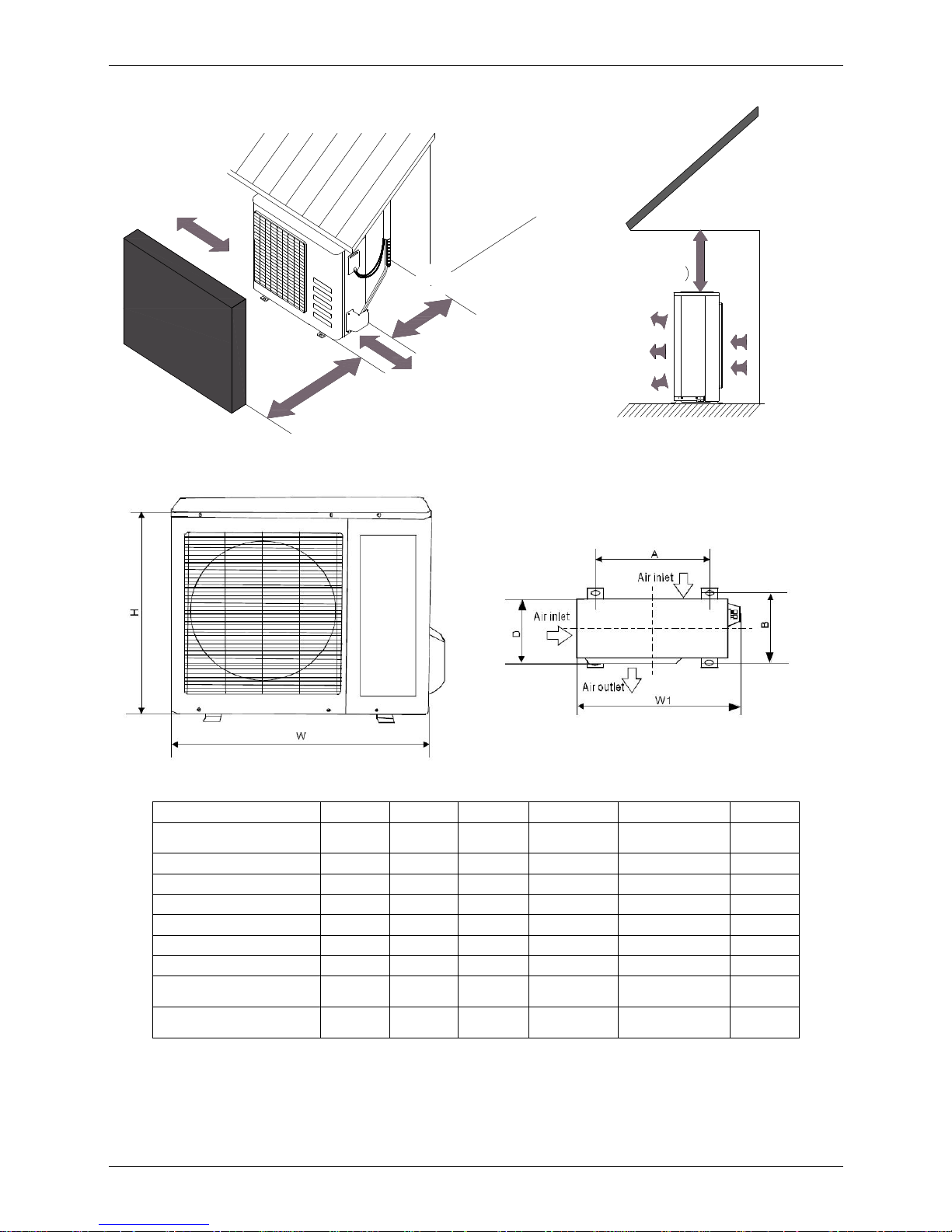
3. Dimensions
More than 30cm
More than 60cm
More than 70cm
More than 30cm
More than 60cm
(Service space
Fence or
obstacles
MODEL W D H W1 A B
M2OC-14HRDN1-Q
M2OC-14HRDN1
760 285 590 823 530 290
M2OC-18HRDN1 845 320 700 908 560 335
M2OC1-18HRDN1-Q 845 320 700 908 560 335
M3OC1-21HRDN1-Q 845 320 700 908 560 335
M3OC-27HRDN1 845 320 700 908 560 335
M3OC1-27HRDN1-Q 845 320 700 908 560 335
M4OC-24HRDN1-Q
845 320 700 908 560 335
M4OC-27HRDN1
M4OC1-27HRDN1-Q
900 315 860 980 590 333
M4OC-36HRDN1-Q
M5OA-36HRDN1-Q
990 345 965 1075 624 366
Page 6
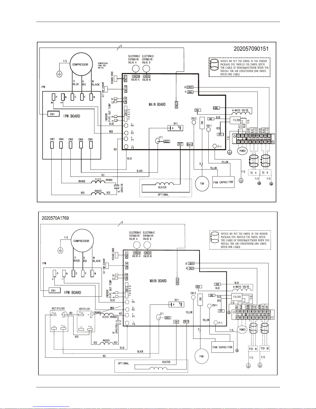
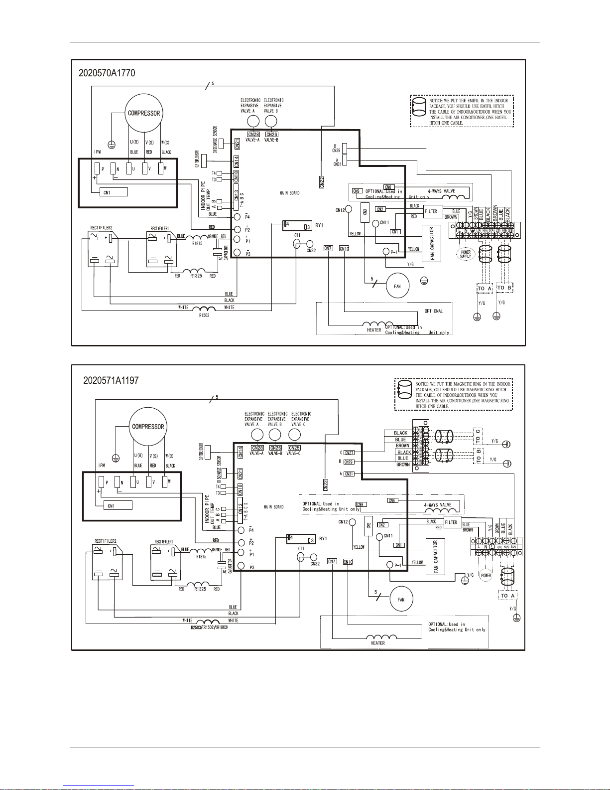
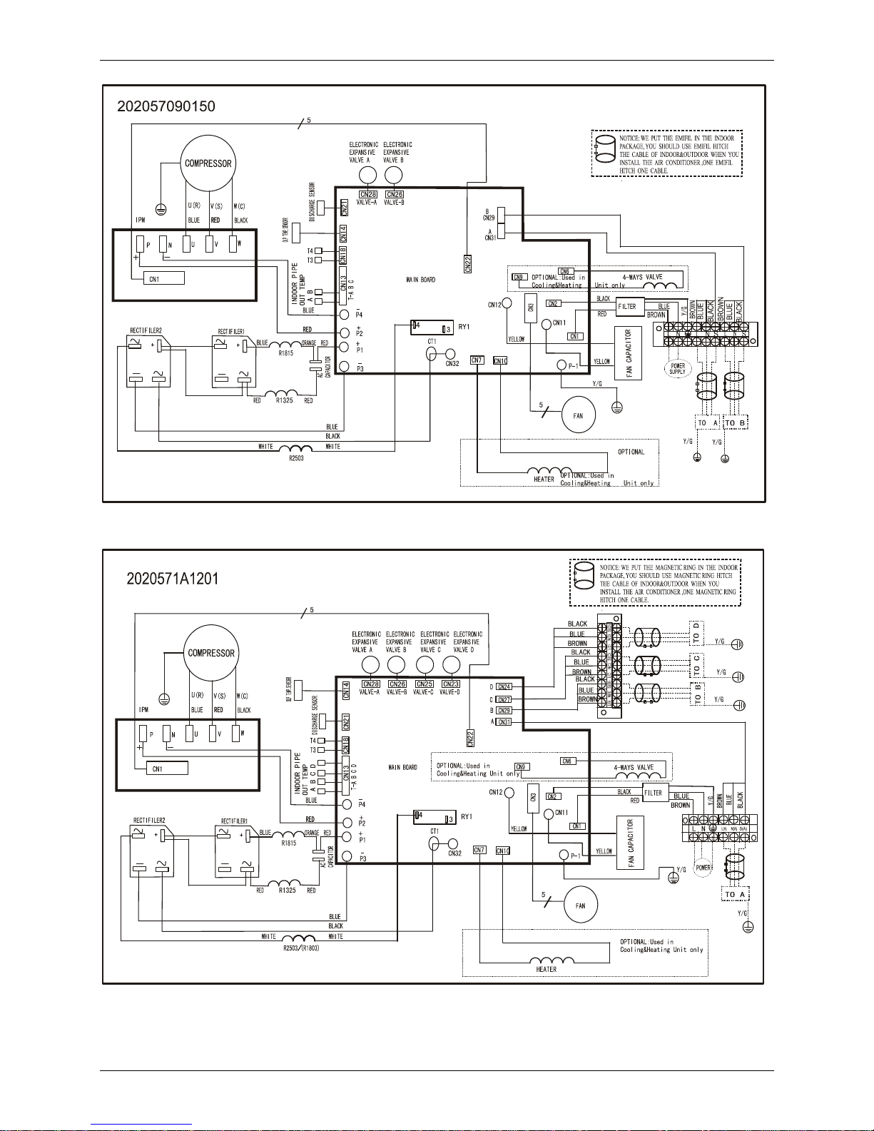
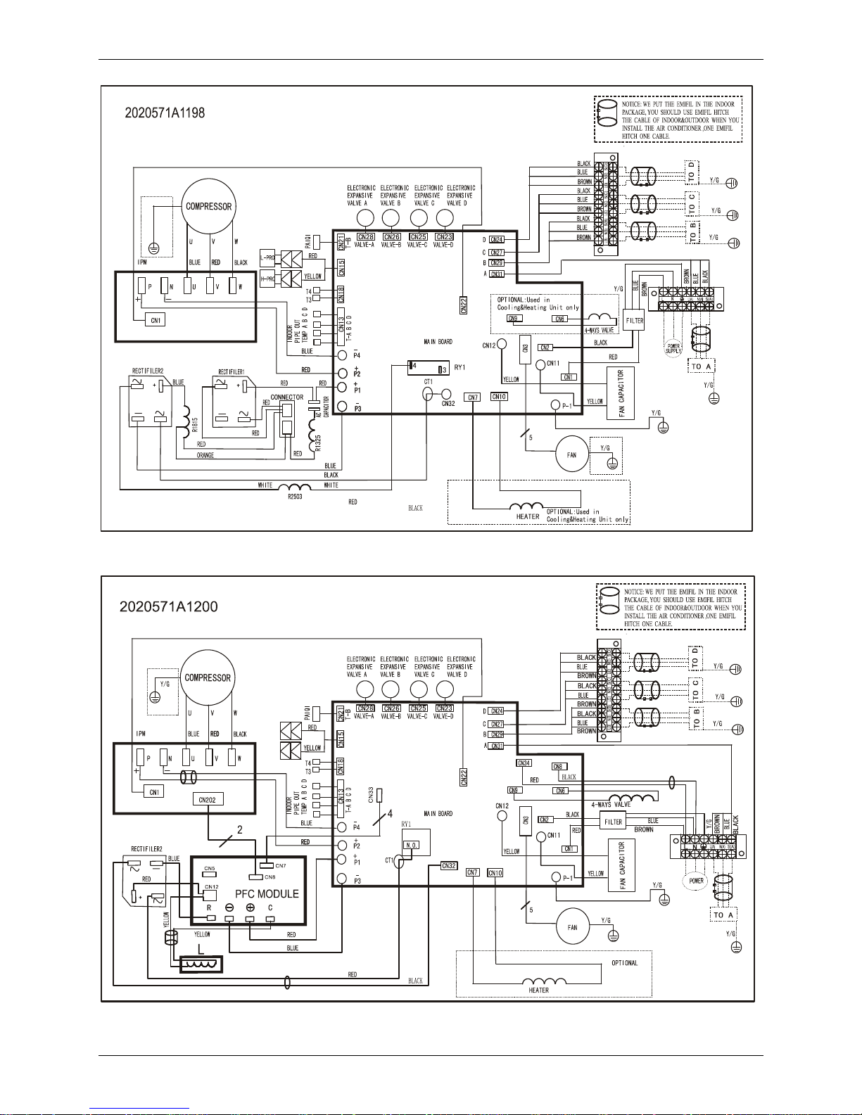
4. Wiring Diagram
4.1 M2OC-14HRDN1-Q
4.2 M2OC-14HRDN1
Page 7
4.3 M2OC1-18HRDN1-Q
4.4 M3OC1-21HRDN1-Q M3OC1-27HRDN1-Q M3OC-27HRDN1
Page 8
4.5 M2OC-18HRDN1
4.6 M4OC-24HRDN1-Q
Page 9
4.7 M4OC1-27HRDN1-Q、M4OC-27HRDN1
4.8 M4OC-36HRDN1-Q
Page 10
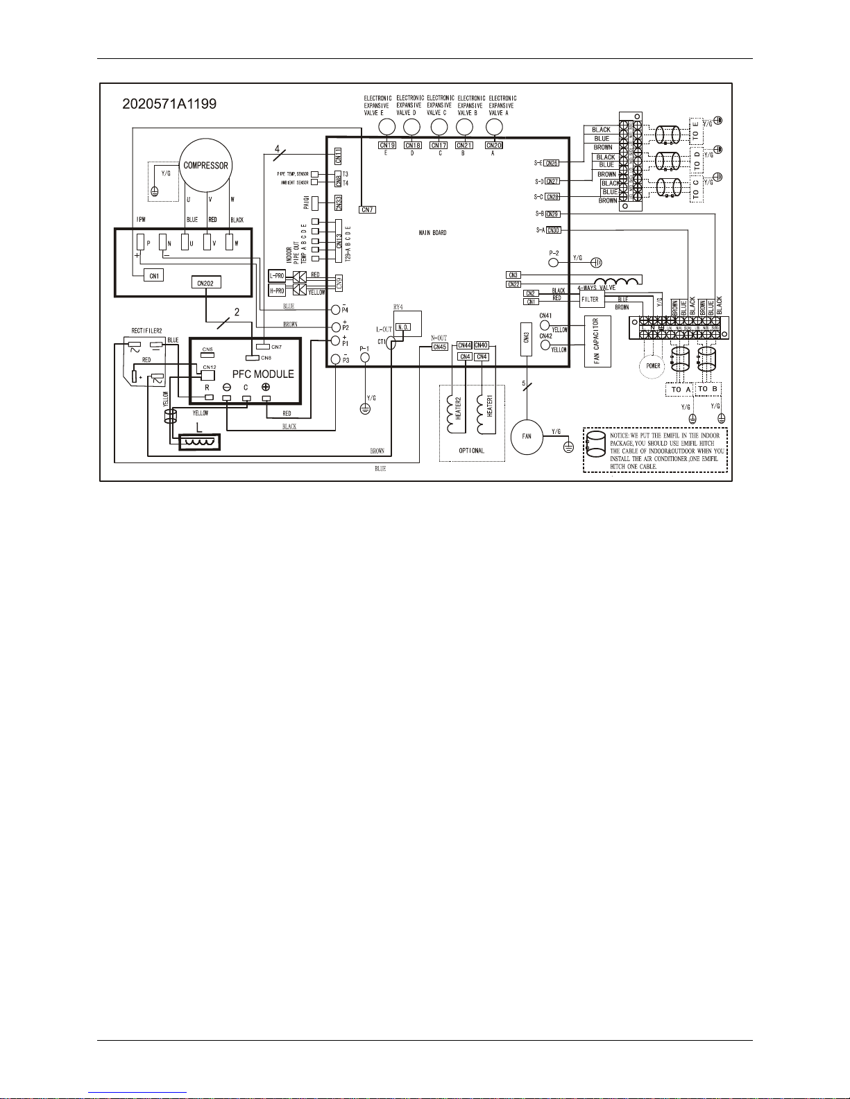
4.9 M5OA-36HRDN1-Q
Page 11
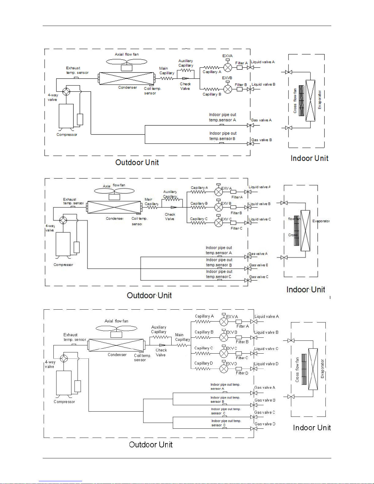
5. Refrigeration Cycle Diagram
5.1 Refrigeration circuit drawing of inverter binary type
4.2 Refrigeration circuit drawing of inverter trinary type
5.3 Refrigeration circuit drawing of inverter quadplex type
Page 12
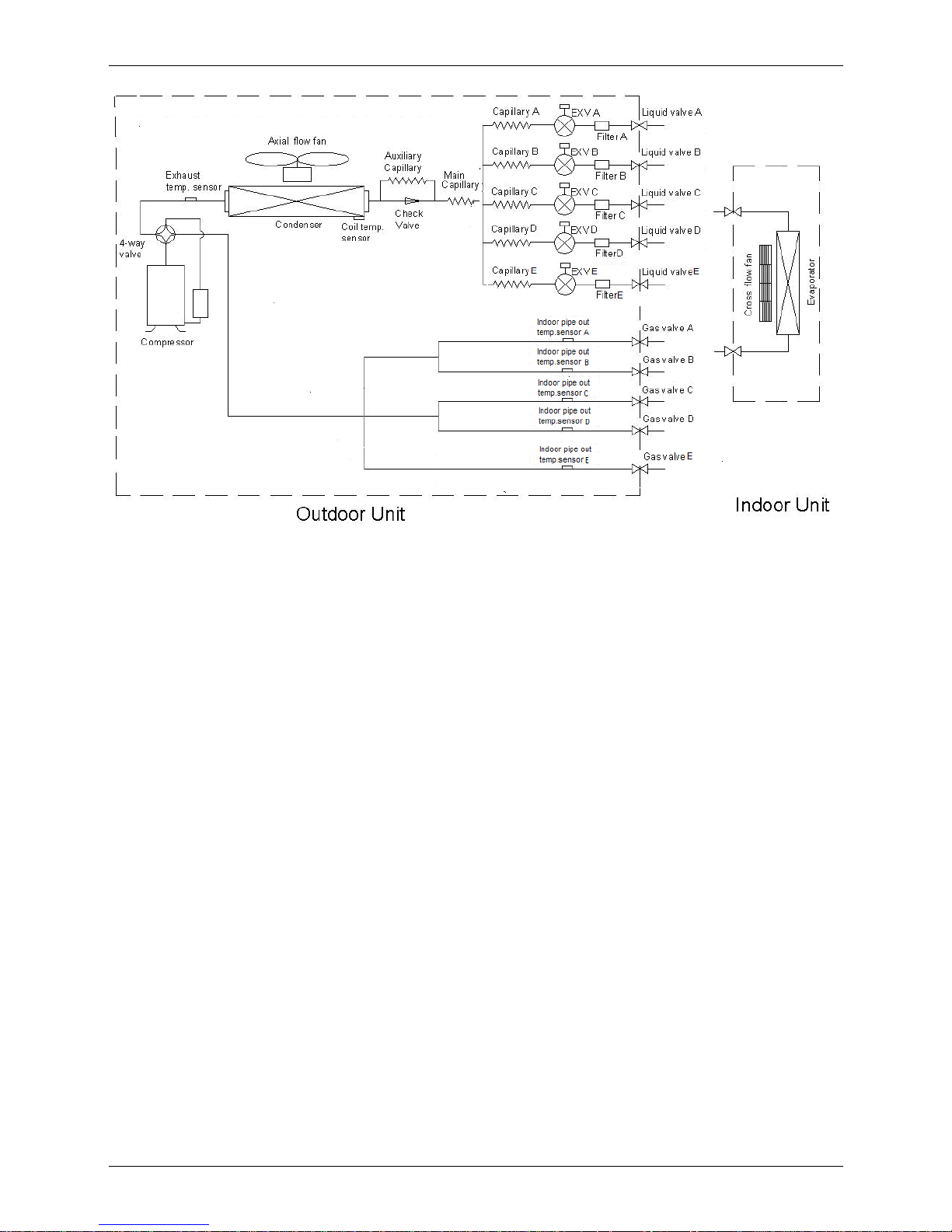
5.4 Refrigeration circuit drawing of inverter quintuple type
Page 13
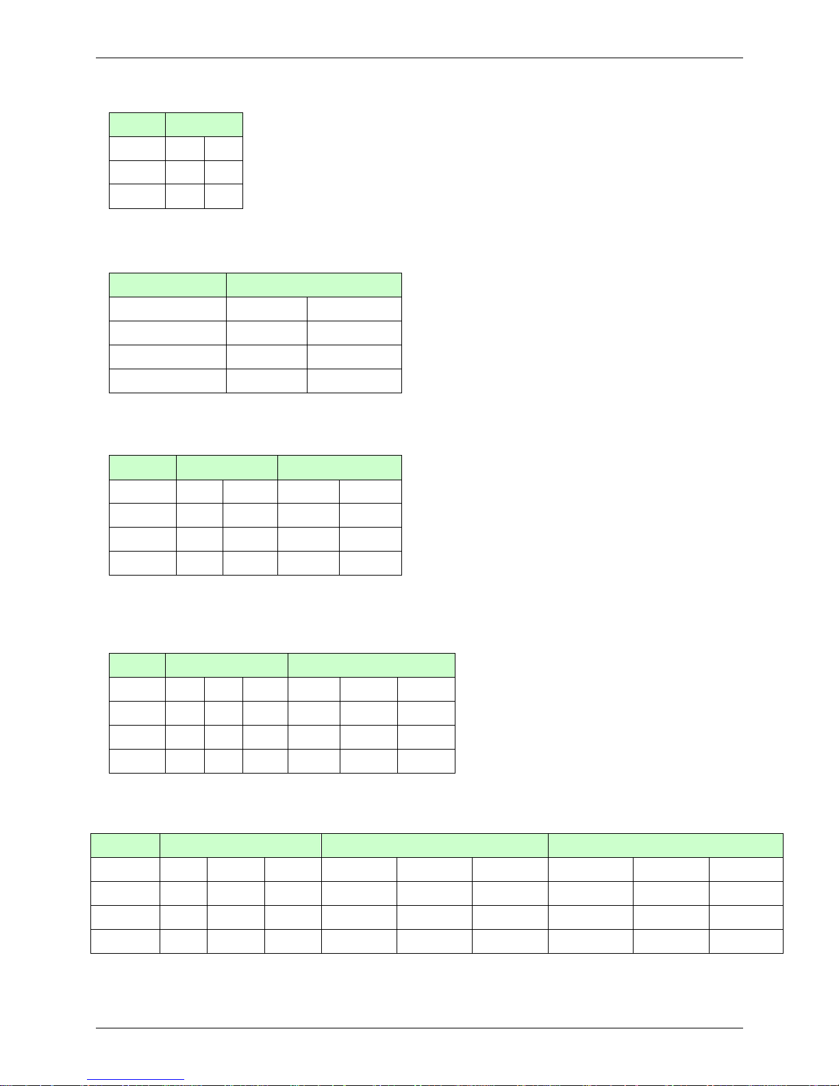
6. Indoor units combination
6.1 Indoor unit combination for M2OC-14HRDN1-Q、M2OC-14HRDN1
One unit Two unit
7 7+7 9+9
9 7+9 9+12
12 7+12
Note: There should be no more than one cassette or duct or console or ceiling & floor unit.
6.2 Indoor unit combination for M2OC1-18HRDN1-Q、M2OC-18HRDN1
One unit Two unit
7 7+7 9+9
9 7+9 9+12
12 7+12 12+12
18 7+18
Note: The 18k indoor unit should only be wall mounted unit.
6.3 Indoor unit combination for M3OC1-21HRDN1-Q
One unit Two unit Three unit
7 7+7 9+9 7+7+7 7+9+12
9 7+9 9+12 7+7+9 9+9+9
12 7+12 9+18 7+7+12 9+9+12
18 7+18 12+12 7+9+9
Note: There should be no more than one cassette or duct or console or ceiling & floor unit. And the 18k indoor unit
should only be wall mounted unit.
6.4 Indoor unit combination for M3OC1-27HRDN1-Q、M3OC-27HRDN1
One unit
Two unit Three unit
7 7+7 9+9 12+12 7+7+7 7+9+9 9+9+9
9 7+9 9+12 12+18 7+7+9 7+9+12 9+9+12
12 7+12 9+18 7+7+12 7+12+12 9+12+12
18 7+18 7+7+18
Note: The 18k indoor unit should only be wall mounted unit.
6.5 Indoor unit combination for M4OC-24HRDN1-Q
One unit Two unit Three unit Four unit
7 7+7 9+9 12+12 7+7+7 7+9+9 9+9+9 7+7+7+7 7+7+9+9 9+9+9+9
9 7+9 9+12 12+18 7+7+9 7+9+12 9+9+12 7+7+7+9 7+7+9+12 9+9+9+12
12 7+12 9+18 7+7+12 7+12+12 9+12+12 7+7+7+12 7+9+9+9
18 7+18 7+7+18 7+9+9+12
Note: The 18k indoor unit should only be wall mounted unit.
Page 14
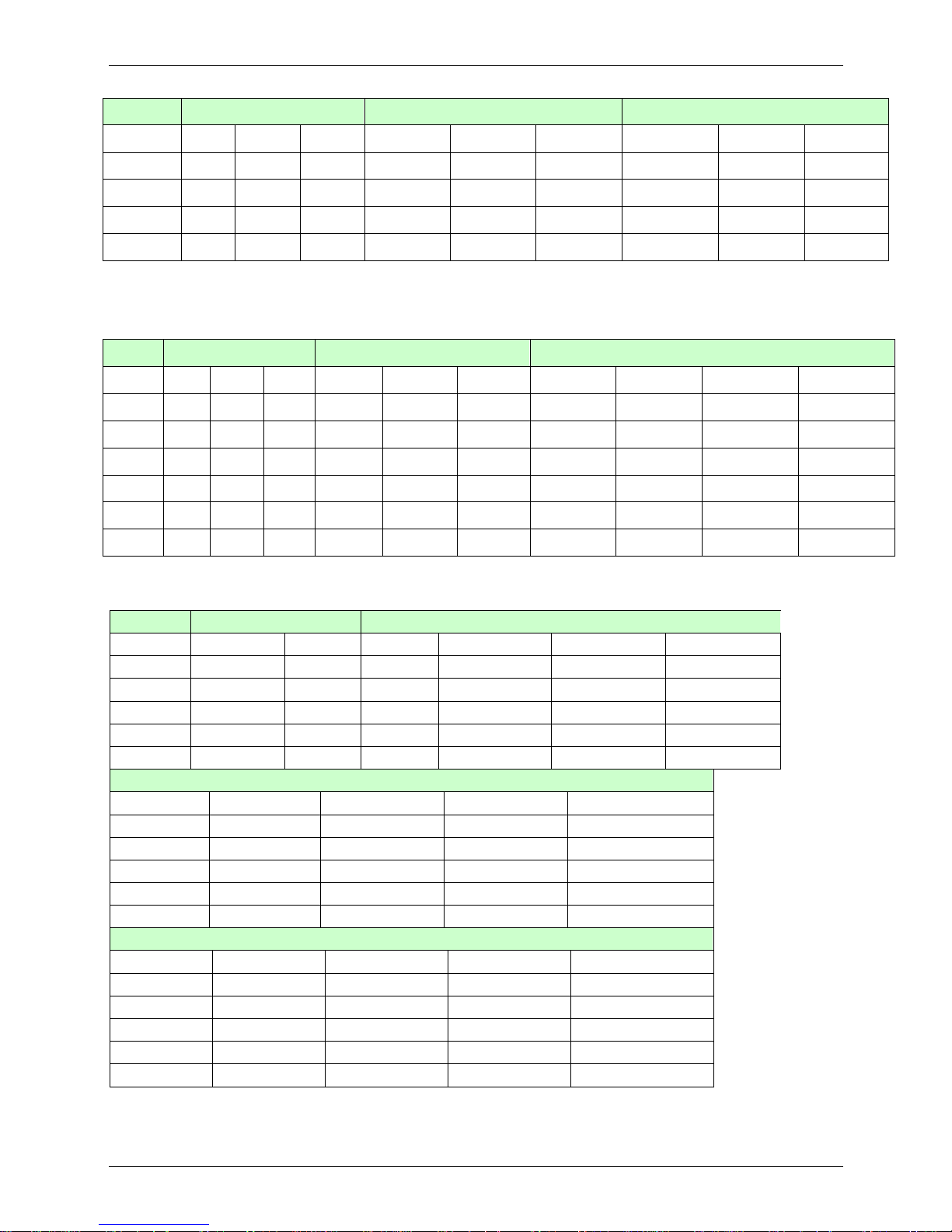
6.6 Indoor unit combination for M4OC1-27HRDN1-Q、M4OC-27HRDN1
One unit Two unit Three unit Four unit
7 7+7 9+9 12+12 7+7+7 7+9+12 9+9+9 7+7+7+7 7+7+9+9 7+9+9+12
9 7+9 9+12 12+18 7+7+9 7+9+18 9+9+12 7+7+7+9 7+7+9+12 7+9+12+12
12 7+12 9+18 18+18 7+7+12 7+12+12 9+9+18 7+7+7+12 7+7+12+12 9+9+9+9
18 7+18 7+7+18 7+12+18 9+12+12 7+7+7+18 7+9+9+9 9+9+9+12
7+9+9 12+12+12 9+12+18
6.7 Indoor unit combination for M4OC-36HRDN1-Q
6.8 Indoor unit combination for M5OA-36HRDN1-Q
One Unit Two Unit Three Unit
7 7+7 9+12 7+7+7 7+9+18 9+9+18 12+18+18
9 7+9 9+18 7+7+9 7+12+12 9+12+12 18+18+18
12 7+12 12+12 7+7+12 7+12+18 9+12+18
18 7+18 12+18 7+7+18 7+18+18 9+18+18
9+9 18+18 7+9+9 9+9+9 12+12+12
7+9+12 9+9+12 12+12+18
Four Unit
7+7+7+7 7+7+9+18 7+9+9+18 7+12+18+18 9+9+18+18
7+7+7+9 7+7+12+12 7+9+12+12 9+9+9+9 9+12+12+12
7+7+7+12 7+7+12+18 7+9+12+18 9+9+9+12 9+12+12+18
7+7+7+18 7+7+18+18 7+9+18+18 9+9+9+18 12+12+12+12
7+7+9+9 7+9+9+9 7+12+12+12 9+9+12+12 12+12+12+18
7+7+9+12 7+9+9+12 7+12+12+18 9+9+12+18
Five Unit
7+7+7+7+7 7+7+7+9+18 7+7+9+12+18 7+9+9+12+18 9+9+9+12+12
7+7+7+7+9 7+7+7+12+18 7+7+12+12+18 7+9+12+12+12 9+9+9+12+18
7+7+7+7+12 7+7+7+18+18 7+9+9+9+9 7+9+12+12+18 9+9+12+12+12
7+7+7+7+18 7+7+9+9+9 7+9+9+9+12 9+9+9+9+9 9+12+12+12+12
7+7+7+9+9 7+7+9+9+12 7+9+9+9+18 9+9+9+9+12 12+12+12+12+12
7+7+7+9+12 7+7+9+9+18 7+9+9+12+12 9+9+9+9+18
One unit
Two unit Three unit Four unit
7 7+7 9+9 12+12 7+7+7 7+12+12 9+12+18 7+7+7+7 7+7+12+12 7+9+12+18 9+9+12+12
9 7+9 9+12 12+18 7+7+9 7+12+18 9+18+18 7+7+7+9 7+7+12+18 7+9+18+18 9+9+12+18
12 7+12 9+18 18+18 7+7+12 7+18+18 12+12+12 7+7+7+12 7+7+18+18 7+12+12+12 9+12+12+12
18 7+18
7+7+18 9+9+9 12+12+18 7+7+7+18 7+9+9+9 7+12+12+18 9+12+12+18
7+9+9 9+9+12 12+18+18 7+7+9+9 7+9+9+12 9+9+9+9 12+12+12+12
7+9+12 9+9+18 7+7+9+12 7+9+9+18 9+9+9+12 12+12+12+18
7+9+18 9+12+12
7+7+9+18 7+9+12+12 9+9+9+18
Page 15
7. Electronic control function
7.1 Abbreviation
T1: Indoor ambient temperature
T2: Coil temperature of indoor heat exchanger middle.
T2B: Coil temperature of indoor heat exchanger outlet.
T3: Coil temperature of outdoor heat exchanger
T4: Outdoor ambient temperature
T5: Compressor discharge temperature
Ts: Setting temp.
7.2 Electric Control working environment.
7.2.1 Input voltage: 190~264V.
7.2.2 Input power frequency:50Hz.
7.2.3 Indoor fan normal working amp. is less than 1A.
7.2.4 Outdoor fan. Normal working amp. is less than 1.5A.
7.2.5 Four-way valve normal working amp. is less than 1A.
7.2.6 Swing motor: DC12V.
7.3 Outdoor unit’s digital display tube
There is a digital display tube in outdoor PCB.
Digital display tube display function
In standby , the LED displays “- -”
In compressor operation, the LED display the running frequency,
In defrosting mode, The LED displays “dF” or alternative displays between running frequency and
“dF”(each displays 2s)
In compressor pre-heating, The LED displays “- -”
In protection or malfunction, the LED displays error code or protection code.
7.4 Outdoor unit point check function
There is a check switch in outdoor PCB.
Push the switch SW1 to check the states of unit when the unit is running. The digital display tube will display
the follow procedure when push SW1 each time.
For units except M5OA-36HRDN1-Q model:
Display Remark
1
Indoor unit capacity demand code
2
Outdoor unit running mode code Off:0, Cooling:1, Heating:2
3
Amendatory capacity demand code
4
Outdoor unit fan motor state Off:0, Low speed:1, High speed:2
5
Evaporator outlet temp. for 1# indoor unit Actual data
6
Evaporator outlet temp. for 2# indoor unit Actual data
7
Evaporator outlet temp. for 3# indoor unit Actual data
8
Evaporator outlet temp. for 4# indoor unit Actual data
9
Condenser pipe temp. Actual data
10
Ambient temp. Actual data
11
Compressor discharge temp. Actual data
12
Inverter current Actual data
Page 16

13
EXV open angle for 1# indoor unit Actual data/8
14
EXV open angle for 2# indoor unit Actual data/8
15
EXV open angle for 3# indoor unit Actual data/8
16
EXV open angle for 4# indoor unit Actual data/8
17
Power supply of outdoor unit AD data
18 Indoor unit number The indoor unit can communicate with outdoor unit well.
19 The last error or protection code 00 means no malfunction
20
frequency value Actual data
21 Ambient temp. of 1# indoor unit Actual data
22 Condenser pipe temp. of 1# indoor unit Actual data
23
Ambient temp. of 2# indoor unit Actual data
24 Condenser pipe temp. of 2# indoor unit Actual data
25 Ambient temp. of 3# indoor unit Actual data
26
Condenser pipe temp. of 3# indoor unit Actual data
27 Ambient temp. of 4# indoor unit Actual data
28 Condenser pipe temp. of 4# indoor unit Actual data
29
―― Check point over
For M5OA-36HRDN1-Q model:
Display Remark
1
No. of indoor units in good connection Actual data
2
Outdoor unit running mode code Off:0, Cooling:2, Heating:3, Forced cooling:4
3
A indoor unit capacity
The capacity unit is horse power. If the indoor unit is not
connected, the digital display tube will show: “――”
4
B indoor unit capacity
5
C indoor unit capacity
6
D indoor unit capacity
7
E indoor unit capacity
8
A Indoor unit capacity demand code
9
B Indoor unit capacity demand code
10
C Indoor unit capacity demand code
11
D Indoor unit capacity demand code
12
E Indoor unit capacity demand code
13
Total indoor units amendatory capacity
demand code
14
The frequency corresponding to the total
indoor units amendatory capacity demand
15
The frequency after the frequency limit
16
The frequency sending to compressor control
chip
17
A indoor unit evaporator outlet temp.(T2BA)
If the temp. is lower than -9 degree, the digital display tube will
show “-9”.If the temp. is higher than 70 degree, the digital display
tube will show “70”. If the indoor unit is not connected, the digital
display tube will show: “――”
18
B indoor unit evaporator outlet temp.(T2BB)
19
C indoor unit evaporator outlet temp.(T2BC)
20
D indoor unit evaporator outlet temp.(T2BD)
21
E indoor unit evaporator outlet temp.(T2BE)
22
A indoor unit room temp.(T1A)
23
B indoor unit room temp.(T1B)
24
C indoor unit room temp.(T1C)
25
D indoor unit room temp.(T1D)
26
E indoor unit room temp.(T1E)
Page 17

27
A indoor unit evaporator outlet temp.(T2BA)
If the temp. is lower than -9 degree, the digital display tube will
show “-9”.If the temp. is higher than 70 degree, the digital display
tube will show “70”. If the indoor unit is not connected, the digital
display tube will show: “――”
28
B indoor unit evaporator outlet temp.(T2BB)
29
C indoor unit evaporator outlet temp.(T2BC)
30
D indoor unit evaporator outlet temp.(T2BD)
31
E indoor unit evaporator outlet temp.(T2BE)
32
Condenser pipe temp.(T3)
33
Outdoor ambient temp.(T4)
34
Compressor discharge temp.(Tp) The display value is between 30~120 degree. If the temp. is lower
than 30 degree, the digital display tube will show “30”.If the temp.
is higher than 99 degree, the digital display tube will show single
digit and tens digit. For example, the digital display tube show
“0.5”,it means the compressor discharge temp. is 105 degree.)
35
AD value of current
The display value is hex number.
36
AD value of voltage
37
EXV open angle for A indoor unit
Actual data/4.
If the value is higher than 99, the digital display tube will show
single digit and tens digit.
For example ,the digital display tube show “2.0”,it means the EXV
open angle is 120×4=480p.)
38
EXV open angle for B indoor unit
39
EXV open angle for C indoor unit
40
EXV open angle for D indoor unit
41
EXV open angle for E indoor unit
42
Frequency limit symbol
Bit7 0
The display
value is hex
number. For
example, the
digital display
tube show
2A,then Bit5=1,
Bit3=1, Bit1=1.
It means
frequency limit
caused by
T4,T3 and
current.
Bit6 0
Bit5
Frequency limit caused by T4.
Bit4
Frequency limit caused by T2.
Bit3
Frequency limit caused by T3.
Bit2
Frequency limit caused by Tp.
Bit1
Frequency limit caused by current
Bit0
Frequency limit caused by voltage
43
Average value of T2 (Sum T2 value of all indoor units)/(indoor units number)
44
Outdoor unit fan motor state Off:0, High speed:1, Med speed:2, Low speed:3
45
The last error or protection code 00 means no malfunction
7.4.1 Frequency of compressor:
Display Frequency of compressor (Hz)
30 30
-- Stand by
60 60
7.4.2 Running mode:
Display Corresponding mode
0 Off
1 Cooling mode
2 Heating mode
Page 18

7.4.3 Capacity demand:
Cooling mode
Capacity 2000-2
500
2000-2
500
3000-3
800
4500-5
000
5000-5
500
5500-6
100
6100-7
000
7000-7
500
7500-8
000
>7500
Correspondi
ng Code
1 2 3 4 5 6 7 8 9 >=10
Heating mode
Capacity 2000-2
500
2000-2
500
3000-3
800
4500-5
000
5500-6
100
6100-7
000
6100-7
000
7000-7
500
7500-8
000
>8000
Correspondin
g Code
1 2 3 4 5 6 7 8 9-10 >=11
Note:
The capacity is just for reference.
Page 19

7.4.4Number of indoor unit
Display Number of indoor unit
1 1
2 2
3 3
7.4.5 Outdoor ambient temp:
Display Corresponding temp.
Display
Corresponding
temp.
Display
Corresponding
temp.
15 -7.5 50 10 80 25
16 -7 51 10.5 81 25.5
17 -6.5 52 11 82 26
18 -6 53 11.5 83 26.5
19 -5.5 53 11.5 84 27
20 -5 54 12 85 27.5
21 -4.5 55 12.5 86 28
22 -4 56 13 87 28.5
23 -3.5 57 13.5 88 29
24 -3 58 14 89 29.5
26 -2 59 14.5 90 30
27 -1.5 60 15 91 30.5
28 -1 61 15.5 92 31
29 -0.5 62 16 93 31.5
30 0 63 16.5 93 31.5
31 0.5 63 16.5 94 32
32 1 64 17 95 32.5
33 1.5 65 17.5 96 33
34 2 65 17.5 97 33.5
35 2.5 66 18 98 34
36 3 67 18.5 99 34.5
37 3.5 68 19 10. 35~40
38 4 69 19.5 11. 40~45
39 4.5 70 20 12. 45~50
40 5 71 20.5 13. 50~55
41 5.5 72 21 14. 55~60
42 6 73 21.5 15. 60~65
43 6.5 74 22 16. 65~70
44 7 75 22.5
45 7.5 75 22.5
46 8 76 23
47 8.5 77 23.5
48 9 78 24
49 9.5 79 24.5
Page 20

7.4.6 Opening degree of electronic expansion valve:
Opening degree equals the display data times 8
7.5 Protection
7.5.1 Three minutes delay at restart for compressor.
7.5.2 Temperature protection of compressor discharge.
When the compressor discharge temp. is getting higher, the running frequency will be limited as below
rules:
----If 102℃<T5<115 , decrease the freq℃ uency to the lower level every 2 minutes till to F1.
---If T5>115℃ for 10 seconds, the compressor will stop and restart till T5<90℃.
7.5.3 Under voltage protection
VOLLIMT1
VOLTAGE
No limit
VOLLIMT2
VOLLIMT3
Off
VOLFRE2
VOLFRE1
VOLREL1
VOLREL2
VOLREL3
Mode VOLLIMT1(V) VOLLIMT2(V) VOLLIMT3(V) VOLREL1(V) VOLREL2(V) VOLREL3(V) VOLFRE1(Hz) VOLFRE2(Hz)
M2OC-14HRDN1 220 200 80 250 210 100 62 54
M2OC-14HRDN1-Q 220 200 80 250 210 100 62 54
M2OC-18HRDN1 230 200 80 260 210 100 62 54
M2OC1-18HRDN1-Q
230 200 120 260 210 135 62 54
M3OC1-21HRDN1-Q
245 220 80 265 240 100 78 45
M3OC-27HRDN1 245 220 80 265 240 100 78 45
M3OC1-27HRDN1-Q
245 220 120 265 240 135 78 45
M4OC-24HRDN1-Q 245 220 120 265 240 135 78 45
M4OC-27HRDN1 221 210 80 260 225 100 62 54
M4OC1-27HRDN1-Q
221 210 80 260 225 100 53 44
M4OC-36HRDN1-Q 200 185 80 210 195 100 54 42
For M5OA-36HRDN1-Q,
VO LT_RST1_A DD
VO LTAGE
No limit
VO LT_LTM1_ADD
VOLT_RS T2_ADD
VO LT_LT M2_ADD
VO LT_LT M_FR EQ 1_ADD
VO LT_LT M_F R EQ 2 _ADD
Page 21

VOLT_RST1_ADD=210V, VOLT_LIM1_ADD=200V, VOLT_RST2_ADD=195V, VOLT_LIM2_ADD=185V.
VOLT_LIM_FREQ1_ADD=54Hz, VOLT_LIM_FREQ2_ADD=42Hz.
7.5.4 Compressor current limit protection
If the compressor current exceeds the current limit value for 10 seconds, the compressor frequency will be
limited as below table.
For models except M5OA-36HRDN1-Q.
Cooling mode:
Current frequency(Hz) Current limit value(A) Frequency limit
COOL_F10 ICOOLLMT6 Decrease the frequency to COOL_F4 and
run at COOL_F4 for 3 minutes.
After that, the frequency will be adjusted
according to the capacity demand and rise
to the upper level every 3 minutes
(When the frequency>COOL_F4 via
capacity demand).
COOL_F9 ICOOLLMT5
COOL_F8 ICOOLLMT4
COOL_F7 ICOOLLMT3
COOL_F6 ICOOLLMT2
COOL_F5 ICOOLLMT1
If the current frequency is lower than COOL_F4, the frequency will not be limited.
After 10s of the compressor start, if the current>ICOOL, the AC will display the failure for 30 seconds
and stop. The AC will restart 3 minutes later.
Heating mode:
Current frequency(Hz) Current limit value(A) Frequency limit
HEAT_F12 IHEATLMT8 Decrease the frequency to HEAT_F4 and
run at HEAT_F4 for 3 minutes.
After that, the frequency will be adjusted
according to the capacity demand and rise
to the upper level every 3 minutes
(When the frequency>Heat_F4 via capacity
demand).
HEAT_F11 IHEATLMT7
HEAT_F10 IHEATLMT6
HEAT_F9 IHEATLMT5
HEAT_F8 IHEATLMT4
HEAT_F7 IHEATLMT3
HEAT_F6 IHEATLMT2
HEAT_F5 IHEATLMT1
If the current frequency is lower than HEAT_F4, the frequency will not be limited.
After 10s of the compressor start, if the current>IHEAT, the AC will display the failure for 30 seconds
and stop. The AC will restart 3 minutes later.
For M5OA-36HRDN1-Q model:
Cooling mode:
Current frequency
(Hz)
Current limit value(A)
Frequency limit
COOL_F16 ICOOLLMT12 Decrease the frequency to COOL_F4 and run at
COOL_F4 for 3 minutes.
After that, the frequency will be adjusted according to
the capacity demand and rise to the upper level every
3 minutes
(When the frequency>COOL_F4 via capacity
demand).
COOL_F15 ICOOLLMT11
COOL_F14 ICOOLLMT10
COOL_F13 ICOOLLMT9
COOL_F12 ICOOLLMT8
COOL_F11 ICOOLLMT7
COOL_F10 ICOOLLMT6
Page 22

COOL_F9 ICOOLLMT5
COOL_F8 ICOOLLMT4
COOL_F7 ICOOLLMT3
COOL_F6 ICOOLLMT2
COOL_F5 ICOOLLMT1
If the current frequency is lower than COOL_F4, the frequency will not be limited.
After 10s of the compressor start, if the current>ICOOL, the AC will display the failure for 30 seconds
and stop. The AC will restart 3 minutes later.
Heating mode:
Current frequency
(Hz)
Current limit value(A)
Frequency limit
HEAT_F16 IHEATLMT12 Decrease the frequency to HEAT_F4 and run at
HEAT_F4 for 3 minutes.
After that, the frequency will be adjusted according to
the capacity demand and rise to the upper level every
3 minutes
(When the frequency>Heat_F4 via capacity
demand).
HEAT_F15 IHEATLMT11
HEAT_F14 IHEATLMT10
HEAT_F13 IHEATLMT9
HEAT_F12 IHEATLMT8
HEAT_F11 IHEATLMT7
HEAT_F10 IHEATLMT6
HEAT_F9 IHEATLMT5
HEAT_F8 IHEATLMT4
HEAT_F7 IHEATLMT3
HEAT_F6 IHEATLMT2
HEAT_F5 IHEATLMT1
If the current frequency is lower than HEAT_F4, the frequency will not be limited.
After 10s of the compressor start, if the current>IHEAT, the AC will display the failure for 30 seconds
and stop. The AC will restart 3 minutes later.
6.5.5 Indoor / outdoor units communication protection
If the indoor units can not receive the feedback signal from the outdoor units for 2 minutes, the AC will stop
and display the failure.
7.5.6 High condenser coil temp. protection.
When T3>65 for ℃ 3 seconds, the compressor will stop while the indoor fan and outdoor fan will continue.
When T3<52 , the protection will release℃ and the compressor will restart after 3 minutes.
7.5.7 Outdoor unit anti-freezing protection
When T2B<0 for 250 seconds℃ , the indoor unit capacity demand will be zero and resume to normal when
T2B>10 .℃
7.5.8 Oil return
Running rules:
Page 23

1. If the compressor frequency keeps lower than RECOILINFRE for Te minutes, the AC will rise the
frequency to RECOILFRE for Tf seconds and then resume to former frequency. For M4OC-36HRDN1-Q,
RECOILINFRE=45Hz, RECOILFRE=48Hz,Te=120,Tf=180; For M5OA-36HRDN1-Q, RECOILINFRE=45Hz,
RECOILFRE=48Hz, Te=90,Tf=100; For other models, RECOILINFRE=50Hz, RECOILFRE=62Hz,
Te=120,Tf=180.
2. During the Tf seconds, the EXV and indoor units keep the current running mode(except
M5OA-36HRDN1-Q model), the frequency will not be limited by the compressor discharge temp. and the
current. For M5OA-36HRDN1-Q model, the EXV will keep 300p while the indoor units will keep the current
running mode.
3. If the outdoor ambient is higher than 15℃ during the oil return, the AC quit oil return.
7.5.9 Compressor preheating functions
----Preheating permitting condition:
If T4(outdoor ambient temperature)<3 and the machine connects to powe℃ r supply no longer than 5
seconds or if T4<3 and compressor has stopped for over 3 hours, the compressor heating cable will ℃
work.
----Preheating mode:
A weak current flow through the coil of compressor from the wiring terminal of compressor, then the
compressor is heated without operation.
----Preheating release condition:
If T4≧5 or ℃ the compressor starts running, preheating function will stop.
7.5.10 Compressor crankcase heater
When T4<3℃ and the compressor is not running, the crankcase heater will be active.
When T4≧5℃ or the compressor starts up, the crankcase heater will stop work.(For M5OA-36HRDN1-Q,T4
≧8℃)
Page 24

8. Troubleshooting
8.1 Indoor unit error code explanation:
Glory series
NO.
MALFUNCTION DEF TIMER AUTO RUN
1 Indoor EEPROM malfunction
O O O O
2 Indoor / outdoor units communication error
★ ★ ★ ★
3
Zero-crossing signal error O O
★ ★
4 Indoor fan speed has been out of control
O O
★ ★
5
Open circuit or short circuit of outdoor temperature sensor
X O X
★
6
Open circuit or short circuit of T1 or T2 temperature sensor
O O O
★
8 IPM module protection or IGBT over-strong current protection
X X O
★
9
Over voltage or too low voltage protection X O O
★
10
Temperature protection of compressor top O X X
★
11
Inverter compressor drive protection O X
★ ★
12
Mode conflict X O
★ ★
★Flash(at 0.5Hz, Mode conflict at 0.25Hz) O light X(off)
9V series+VERTU series+9A series+Corona series+ R series+Y series+ X series
Display LED STATUS
E0
Indoor EEPROM malfunction
E1 Indoor/ outdoor units communication error
E2 Zero-crossing signal error
E3 Indoor fan speed has been out of control
E5 Open circuit or short circuit of outdoor temperature sensor
E6 Open circuit or short circuit of T1 or T2 temperature sensor
P0 IPM module protection or IGBT over-strong current protection
P1 Over voltage or too low voltage protection
P2 Temperature protection of compressor top
P4 Inverter compressor drive protection
P5 Mode conflict
NEOLA series +PREMIER series +OASIS series:
Display
Operation lamp flash times
Timer lamp
Failure
E0 1 X Indoor EEPROM malfunction
E1 2 X Indoor / outdoor units communication error
E2 3 X Zero-crossing signal error
E3 4 X Indoor fan speed has been out of control
E4
5 X Open or short circuit of T1 temperature sensor
E5
6 X Open or short circuit of T2 temperature sensor
F1
2 O Open or short circuit of T4 temperature sensor
Page 25

F2
3 O Open or short circuit of T3 temperature sensor
F3 4 O Open or short circuit of T5 temperature sensor
F4 5 O Outdoor EEPROM malfunction
F6 7 O Open or short circuit of T2B temperature sensor
P0
1 ☆
IPM module protection or IGBT over-strong current
protection
P1 2
☆
Over voltage or too low voltage protection
P2 3
☆
Temperature protection of compressor top
P4 5
☆
Inverter compressor drive protection
P5 6
☆
Mode conflict
O (light) X (off) ☆ (flash)
Cassette series:
Operation Timer De-frost Alarm LED STATUS
★
X X X Open or short circuit of T1 temperature sensor
X X
★
X Open or short circuit of T2 temperature sensor
X
★
X X Indoor / outdoor units communication error
X X X
★
Full-water malfunction
★ ★
X X Indoor EEPROM malfunction
★
X X
IPM module protection
★
X X Open or short circuit of T3 or T4 temperature sensor
★
X
Outdoor voltage protection
★ ★ ★ ★
Temperature protection of compressor top
★
X
Mode conflict
★
X Inverter compressor drive protection
★ flash, light, X extinguished.
Ceiling &Floor series:
Operation Timer De-frost Alarm LED STATUS
★
X X X Open or short circuit of T1 temperature sensor
X X
★
X Open or short circuit of T2 temperature sensor
X
★
X X Indoor / outdoor units communication error
X X X
★
Full-water malfunction
★ ★
X X Indoor EEPROM malfunction
★
X X
IPM module protection
★
X X Open or short circuit of T3 or T4 temperature sensor
★
X
Outdoor voltage protection
★
X
X Temperature protection of compressor top
★
X
Mode conflict
★ flash, light, X extinguished.
Page 26

A5 Duct series:
Operation Timer De-frost Alarm
LED STATUS
DISPLAY DIGITAL TUBE
★
X X X Open or short circuit of T1 temperature sensor
E0
X X
★
X Open or short circuit of T2 temperature sensor
E1
X
★
X X Indoor / outdoor units communication error
E2
X X X
★
Full-water malfunction
E3
★ ★
X X Indoor EEPROM malfunction
E4
★
X X
IPM module protection
E5
★
X X
Open or short circuit of T3 or T4 temperature
sensor
E6
★
X
Outdoor voltage protection
P0
★ ★ ★ ★
Temperature protection of compressor top P3
★
◎ X X Inverter compressor drive protection P4
★
X
X Mode conflict P5
★ flash at 5Hz, light, X extinguished ◎flash at 0.5Hz
Console series:
Operation Timer De-frost LED STATUS
★
X X Open or short circuit of T1 temperature sensor
X X
★
Open or short circuit of T2 temperature sensor
X
★
X Indoor / outdoor units communication error
★ ★
X Indoor EEPROM malfunction
★
X
★
IPM module protection
★ ★ ★
Open or short circuit of T3 or T4 temperature sensor
★
X Top temperature protection of compressor
★
◎ X Inverter compressor drive protection
★
X
Mode conflict
★
★
Indoor fan speed has been out of control
★ flash at 5Hz, light, X extinguished
Page 27

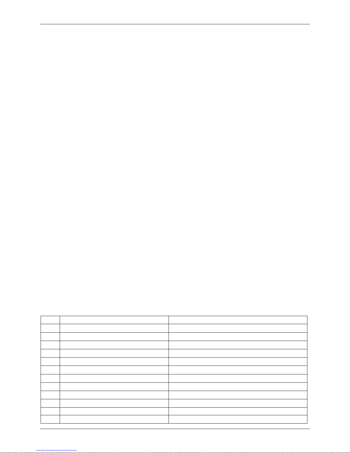
Outdoor unit error code explanation:
For units(except M5OA-36HRDN1-Q model)
Display LED STATUS
E0 Outdoor EEPROM malfunction
E1 No A Indoor unit coil outlet temp. sensor or connector of sensor is defective
E2 No B Indoor unit coil outlet temp. sensor or connector of sensor is defective
E3 No C Indoor unit coil outlet temp. sensor or connector of sensor is defective
E6 No D Indoor unit coil outlet temp. sensor or connector of sensor is defective
E4 Open or short circuit of outdoor unit temperature sensor
E5 Compressor voltage protection
E7 Communication malfunction between IPM board and outdoor main board
P0
Temperature protection of compressor discharge or compressor top.
For M4OC-27HRDN1, M4OC1-27HRDN1-Q,M4OC-36HRDN1-Q,it only means Temperature
protection of compressor discharge
P1 High pressure protection(only for M4OC1-27HRDN1-Q, M4OC-27HRDN1-Q,M4OC-36HRDN1-Q)
P2 Low pressure protection(only for M4OC1-27HRDN1-Q, M4OC-27HRDN1-Q,M4OC-36HRDN1-Q)
P3 Current protection of compressor
P4 IPM module protection
P6 High temperature protection of condenser
P7 Inverter compressor drive protection
Page 28

For M5OA-36HRDN1-Q model
Display LED STATUS
E0 Outdoor EEPROM malfunction
E2 Indoor / outdoor units communication error
E3 Communication malfunction between IPM board and outdoor main board
E4 Open or short circuit of outdoor unit temperature sensor
E5 Compressor voltage protection
E6 PFC module protection
F1 No A Indoor unit coil outlet temp. sensor or connector of sensor is defective
F2 No B Indoor unit coil outlet temp. sensor or connector of sensor is defective
F3 No C Indoor unit coil outlet temp. sensor or connector of sensor is defective
F4 No D Indoor unit coil outlet temp. sensor or connector of sensor is defective
F5 No E Indoor unit coil outlet temp. sensor or connector of sensor is defective
P1 High pressure protection
P2 Low pressure protection
P3 Current protection of compressor
P4 Temperature protection of compressor discharge
P5 High temperature protection of condenser
P6 IPM module protection
Page 29

8.3Trouble shooting
8.3.1 For the indoor unit
8.3.1.1 Indoor EEPROM malfunction
Page 30

8.3.1.2 Indoor / outdoor units communication error
No
No fist time
Yes
Yes
No
Reconnect the wiring
Check wiring on the outdoor
and indoor t er
minal follow
the wiring
diagram. Is all
connecting correctly?
Turn on all indoor unit
by remote controller.
Is
all indoor unit display
Measure Vs, is i
t moving
alternately between positive
value and negative value?
(Vs is the voltage between
Turn off the all indoor
units. Is IPM power LED
lamp On? Refer PIC 3
Is PFC power LED lamp
off? Refer PIC 3.
No
Yes
Start: Power off , then Power on the A/C by the
Breaker. (reconnect the power wire). Is E1
extinguish?
change
IPM
No
No
Yes
Yes
Is indoor units number
correct? C
heck on the
outdoor check poi
nt (18). (2
for dual zone, 3 for tri
zone, 4
for qua zone). Refer PIC 5.
Is Main board
“ "
lamp on?
Reconnect the wiring
No
A:
Is all the wiring
between t
erminal
and Indoor PCB
change
PFC
No
Yes
No
change the
Indoor PCB
Yes
Power on by remote
controller, Is the E1
extinguish after 3
minutes?
E1 error problem solved. The unit
operation normally.
Is the Reactor
connection.
Reconnect the wiring
Change Outdoor Main
PCB
No
No
Yes
Change
outdoor unit PCB
assembly(include wiring) totally
No second time
A
Yes
Yes
Page 31

Pic 1: Measure the voltage of L2 to S (Vs), is
it moving alternately between positive value
and negative value?
PIC 2, Check the wiring.
PFC (qua-zone only)
PIC 3:IPM
(For dual/tri/qua
-
zone)
Power on
Self-Check OK
Operati
Off is OK
PIC 5: check piont buttom,
pess 18 times for check how many indoor units are
connected.
Page 32

8.3.1.3 Zero-crossing signal error
8.3.1.4 Indoor fan speed has been out of control
Shut off the power supply
and turn it on 1 minute
later. Is it still displaying
the error code?
S h u t o ff t he p o w e r
su p ply, rotate the cross
fan by hand. Does it
rotate properly?
The unit operates normally.
Disassembly the
connection between
fan and motor, check if
the bearing is normal?
Replace the bearing.
Check the wires of
fan motor. Are all the
connections good?
No
Yes
No No
Replace indoor fan motor.
Yes
Correct the connections.No
No
Yes
Yes
Check the resistance value of
indoor fan motor, is it normal?
Replace indoor PCB.
Yes
Page 33

8.3.1.5 Open or short circuit of temperature sensor.
8.3.1.6 Full-water malfunction
Full-water malfunction
Check whether the water-level switch is inserted well
Check whether the water-level switch is broken
Check PCB board or replace the indoor main PCB
Replace the water-level switch
Yes
No
Check whether the water pump is normal
Yes
Insert the water-level switch well
No
Yes
Replace the water pump
No
Page 34

8.3.2 For the outdoor unit
8.3.2 1 Outdoor EEPROM malfunction
Outdoor EEPROM malfunction
Yes
No
Insert the EEPROM well
Replace the outdoor main board
If the EEPROM chip is welded on
PCB, replace the PCB directly.
Otherwise, check whether the
EEPROM chip plugged in PCB
well?
Page 35

8.3.2.2 Voltage protection of compressor
Check the power supply
No
Check the voltage of outdoor unit power supply, whether the voltage
between L(1) and N is about 220VAC
No
Replace the power board, then check whether the system can run
normally
Yes
Yes
Trouble is solved
No
Check whether the voltage of IPM board P and N is 280-400VDC
Replace bridge rectifiers, then check whether the
system can run normally
Trouble is solved
Replace IPM board
No
Yes
No
No
Replace outdoor main board
Voltage protection of compressor
Page 36

8.3.2.3 Communication malfunction between IPM board and outdoor main board
No
Check whether the IPM board has error display
Replace IPM board
Yes
Insert the connecting wiring between the IPM module and the main
board well over again
Trouble is solved
Yes
No
Replace the IPM board
No
Trouble is solved
Yes
No
Replace outdoor PCB
Replace the electric control box
Trouble is solved
Yes
The problem is not
resolved.
Page 37

8.3.2.4 Temperature protection of compressor discharge
Discharge temperature protection of compressor
Check whether the compressor discharge temp. is more than 115°C ?
No
Check whether the wiring connection is right
between compressor discharge temp. sensor and
PCB according to wiring diagrams
Yes
Method: Check whether the resistance of compressor discharge
temp. sensor is right refer to the Appendix 2
No
Correct the wiring connection
Yes
Replace outdoor main board
Judge: The discharge temp. sensor is broken
No
Replace the compressor
discharge temp. sensor
Check whether the refrigerant is leak
Stop leaking and add refrigerant
Yes
Yes
Page 38

8.3.2.5 Temperature protection of compressor top
Judge 2: Whether
refrigerant circulation volume is
normal?
Whether
abnormality is the same after gas charging?
Check refrigerant system (such as clogging of capillary etc.)
Temperature protection of compressor top
Judge 1: Whether
compressor operates?
Yes
No
Whether
the
connection
is
good?
Method:
Charge refrigerant
Yes
Whether
protector is
normal?
No
No
Reconnect and
retest.
No
Replace the protector.
No
Check the outdoor
main PCB. Is there
Yes
Replace the outdoor
main PCB
Yes
Page 39

8.3.2.6 High pressure protection(For M4OC1-27HRDN1-Q, M4OC-27HRDN1-Q,M4OC-36HRDN1-Q,
M5OA-36HRDN1-Q)
High pressure protection
Judge 1: Whether the wiring between the high pressure switch and main
control board is connected well or correctly
Judge 2: Whether the high pressure switch is broken
Yes
No
Connect it well
Method: Short connect the high pressure switch socket, check
whether the system can run normally
Yes
Replace high pressure switch
No
Check whether the refrigerant system is ok
Replace outdoor main board
No
Judge 3: Check whether the outdoor ambient temperature is too high
Yes
Stop the unit
No
Judge 4: Check whether the outdoor unit is bad ventilation
Yes
Make the outdoor unit ventilate well
No
Judge 5: Check whether the heat exchanger is dirty
Yes
Clean the heat exchanger
No
Judge 6: Check whether the refrigerant pipe is blocked
Yes
Let the refrigerant out, then use the high pressure
nitrogen or refrigerant to blow pipe, vacuumize and
charge the refrigerant again
Page 40

8.3.2.7 Low pressure protection (For M4OC1-27HRDN1-Q, M4OC-27HRDN1-Q,M4OC-36HRDN1-Q,
M5OA-36HRDN1-Q)
Low pressure protection
Judge 1: The wiring between the low pressure switch and main control
board is connected well or correctly
Judge 2: Whether the low pressure switch is broken
Connect it well
Method: Short connect the low pressure switch socket, check
whether the system can run normally
Check whether the refrigerant system is ok
Yes
No
Judge 3: Check whether the outdoor ambient temperature is too low
Yes
Stop the unit
No
Judge 4: The refrigerant of the system is leakage
Yes
Method: Connect the pressure gauge to the gauge joint of the system,
check whether the pressure is lower than 0.14MPa
Leak hunting: Charge nitrogen or refrigerant to
the system, if the leakage is serious, there will
be distinct gas leakage “cici” sound; if the
leakage is slight, use the suds (mixture of water
and abluent is also ok if it can make bubble) or
electronic leak detector.
Judge 5: The refrigerant pipe is blocked
Yes
Let the refrigerant out, then use the high pressure
nitrogen or refrigerant to blow pipe, vacuumize and
charge the refrigerant again
No
Replace outdoor main board
No
No
Yes
Replace low pressure switch
Page 41

8.3.2.8 Current protection of compressor
Current protection of compressor
Judge 1: Check whether the input current of the power supply wire is more
than 8.5A (For 18-21K, it is 15A..For 27K(1x3) , it is 15A .For 27K(1x4), it is
Check whether the refrigerant system is ok
Yes
Judge 2: Check whether the outdoor ambient temperature is too high
Yes
Stop the unit
Replace outdoor main board
No
No
Judge 3: Check whether the outdoor unit is bad ventilation
Yes
Make the outdoor unit ventilate well
No
Judge 4: Check whether the heat exchanger is dirty
Yes
Clean the heat exchanger
No
Judge 5: The refrigerant pipe is blocked
Yes
Let the refrigerant out, then use the high pressure
nitrogen or refrigerant to blow pipe, vacuumize and
charge the refrigerant again
Replace the electric control box
Trouble is solved
Yes
The problem is not
resolved.
Page 42

8.3.2.9 IPM module protection
IPM module protection
Check whether the voltage range of P-N on
IPM module is normal? DC277-356V for
14-27KBtu/h; DC277-410V for 36KBtu/h
No
Check whether the input power supply
is correct? 220-240V, 1N, 50Hz
No
Regulate it to correct,
then check whether the
system can work
normally?
Yes
Check whether the power
supply line is connected
correctly and tightly
No
Connect it correctly and
tightly, check ok or not?
No
Yes
Check whether the lines in
E-part box are connected tightly
No
Connect it tightly,
check ok or not?
No
Yes
Check whether the single-phase bridge is
normal? Use the multimeter to measure the
resistance between each two terminals, check
whether there is the condition that value of
resistance is 0
Yes
Replace the
single-phase bridge
No
No
Check whether the connecting line
of every reactor is normal? If the
line is broken, the resistance of the
two ports is ∞(models except for
M5OA-36HRDN1-Q);Check
whether the PFC module
broken(for M5OA-36HRDN1-Q)
Yes
Replace the
connecting line or
reactor or replace
the PFC module
Yes
Check whether the connecting line
between main board and the IPM
module is connected tightly
Yes
Check whether the connecting
line of the compressor is
connected correctly or tightly
Yes
Replace the IPM module, check
whether the system can work
normally?
No
Replace the main board, check
whether the system can work
normally?
Yes
Trouble is solved
Replace the compressor, check
whether the system can work
normally?
Connect it tightly,
check ok or not?
No
No
Yes
Trouble is solved
No
No
Yes
Trouble is solved
Connect it well,
check ok or not?
Page 43

8.3.2.10 High temperature protection of condenser
When outdoor pipe temp. is more than 65°C, the unit will stop, and unit runs again when outdoor pipe
temp. less than 52°C.
Check whether the condenser temperature is more than 65°C
Check whether the resistance of condenser temp.
sensor is correct refer to the Appendix 1
Replace outdoor main board
Let the refrigerant out, then use the high pressure
nitrogen or refrigerant to blow pipe, vacuumize and
charge the refrigerant again
High temperature protection of condenser
No
Yes
No
Replace the temperature sensor
Yes
Judge1: The outdoor temp. is too high
No
Judge 2: Check whether the heat exchanger is dirty
No
Judge 3: The refrigerant pipe is blocked
Clean the heat exchanger
Yes
Yes
Yes
Stop the unit
No
Page 44

8.3.2.11 PFC module protection
8.3.2.12 Inverter compressor drive protection
The trouble shooting is same with one of IPM module protection
PFC module protection
Check whether the connecting line between main
board and the PFC module is connected tightly
No
Connect it tightly, check normal or not
Yes
Check whether the voltage between P
and N of IPM module is 380-390VDC
No
Yes
Replace the outdoor main board
No
Replace the PFC module
Check whether the inductance of PFC module is
Replace the inductance
Page 45

Appendix 1 Temperature Sensor Resistance Value Table (℃--K)
℃
K Ohm
℃
K Ohm
℃
K Ohm
℃
K Ohm
-20 115.266 20 12.6431 60 2.35774 100 0.62973
-19 108.146 21 12.0561 61 2.27249 101 0.61148
-18 101.517 22 11.5000 62 2.19073 102 0.59386
-17 96.3423 23 10.9731 63 2.11241 103 0.57683
-16 89.5865 24 10.4736 64 2.03732 104 0.56038
-15 84.2190 25 10.000 65 1.96532 105 0.54448
-14 79.3110 26 9.55074 66 1.89627 106 0.52912
-13 74.5360 27 9.12445 67 1.83003 107 0.51426
-12 70.1698 28 8.71983 68 1.76647 108 0.49989
-11 66.0898 29 8.33566 69 1.70547 109 0.48600
-10 62.2756 30 7.97078 70 1.64691 110 0.47256
-9 58.7079 31 7.62411 71 1.59068 111 0.45957
-8 56.3694 32 7.29464 72 1.53668 112 0.44699
-7 52.2438 33 6.98142 73 1.48481 113 0.43482
-6 49.3161 34 6.68355 74 1.43498 114 0.42304
-5 46.5725 35 6.40021 75 1.38703 115 0.41164
-4 44.0000 36 6.13059 76 1.34105 116 0.40060
-3 41.5878 37 5.87359 77 1.29078 117 0.38991
-2 39.8239 38 5.62961 78 1.25423 118 0.37956
-1 37.1988 39 5.39689 79 1.21330 119 0.36954
0 35.2024 40 5.17519 80 1.17393 120 0.35982
1 33.3269 41 4.96392 81 1.13604 121 0.35042
2 31.5635 42 4.76253 82 1.09958 122 0.3413
3 29.9058 43 4.57050 83 1.06448 123 0.33246
4 28.3459 44 4.38736 84 1.03069 124 0.32390
5 26.8778 45 4.21263 85 0.99815 125 0.31559
6 25.4954 46 4.04589 86 0.96681 126 0.30754
7 24.1932 47 3.88673 87 0.93662 127 0.29974
8 22.5662 48 3.73476 88 0.90753 128 0.29216
9 21.8094 49 3.58962 89 0.87950 129 0.28482
10 20.7184 50 3.45097 90 0.85248 130 0.27770
11 19.6891 51 3.31847 91 0.82643 131 0.27078
12 18.7177 52 3.19183 92 0.80132 132 0.26408
13 17.8005 53 3.07075 93 0.77709 133 0.25757
14 16.9341 54 2.95896 94 0.75373 134 0.25125
15 16.1156 55 2.84421 95 0.73119 135 0.24512
16 15.3418 56 2.73823 96 0.70944 136 0.23916
17 14.6181 57 2.63682 97 0.68844 137 0.23338
18 13.9180 58 2.53973 98 0.66818 138 0.22776
19 13.2631 59 2.44677 99 0.64862 139 0.22231
Page 46

Appendix 2
Unit: ℃---K Discharge temp. sensor table
-20 542.7 20 68.66 60 13.59 100 3.702
-19 511.9 21 65.62 61 13.11 101 3.595
-18 483 22 62.73 62 12.65 102 3.492
-17 455.9 23 59.98 63 12.21 103 3.392
-16 430.5 24 57.37 64 11.79 104 3.296
-15 406.7 25 54.89 65 11.38 105 3.203
-14 384.3 26 52.53 66 10.99 106 3.113
-13 363.3 27 50.28 67 10.61 107 3.025
-12 343.6 28 48.14 68 10.25 108 2.941
-11 325.1 29 46.11 69 9.902 109 2.86
-10 307.7 30 44.17 70 9.569 110 2.781
-9 291.3 31 42.33 71 9.248 111 2.704
-8 275.9 32 40.57 72 8.94 112 2.63
-7 261.4 33 38.89 73 8.643 113 2.559
-6 247.8 34 37.3 74 8.358 114 2.489
-5 234.9 35 35.78 75 8.084 115 2.422
-4 222.8 36 34.32 76 7.82 116 2.357
-3 211.4 37 32.94 77 7.566 117 2.294
-2 200.7 38 31.62 78 7.321 118 2.233
-1 190.5 39 30.36 79 7.086 119 2.174
0 180.9 40 29.15 80 6.859 120 2.117
1 171.9 41 28 81 6.641 121 2.061
2 163.3 42 26.9 82 6.43 122 2.007
3 155.2 43 25.86 83 6.228 123 1.955
4 147.6 44 24.85 84 6.033 124 1.905
5 140.4 45 23.89 85 5.844 125 1.856
6 133.5 46 22.89 86 5.663 126 1.808
7 127.1 47 22.1 87 5.488 127 1.762
8 121 48 21.26 88 5.32 128 1.717
9 115.2 49 20.46 89 5.157 129 1.674
10 109.8 50 19.69 90 5 130 1.632
11 104.6 51 18.96 91 4.849
12 99.69 52 18.26 92 4.703
13 95.05 53 17.58 93 4.562
14 90.66 54 16.94 94 4.426
15 86.49 55 16.32 95 4.294 B(25/50)=3950K
16 82.54 56 15.73 96 4.167
17 78.79 57 15.16 97 4.045 R(90℃)=5KΩ±3%
18 75.24 58 14.62 98 3.927
19 71.86 59 14.09 99 3.812
Page 47

Appendix 3
1. Reference voltage data:
a) Rectifier : Input :220-230V(AC), output :310V(DC)
b) Inverter module: U,V, W 3ph.
Result
U-V 60-150V(AC)
U-W 60-150V(AC)
V-W 60-150V(AC)
P-N DC 310V
2. Check the Diode Bridge component ( In wiring diagram, rectifier)
Remark: If this part is abnormal, the LED will not light.
Multi-meter Result
Forward Resistance Backward Resistance
+ _
Infinite Infinite
~
+
~1.7M ohm Infinite
~ - ~
~1.7M ohm Infinite
~
~ +
- ~
 Loading...