

Page 1
INDOOR UNIT INSTALLATION
1
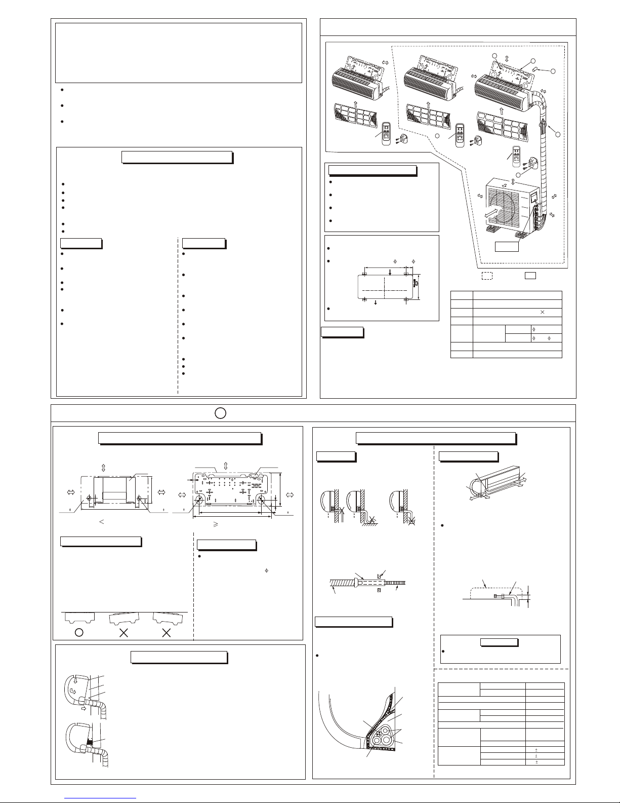
Indoor/Outdoor Unit Installation Illustration
1. Run the drain hose sloping downward. Do
not install the drain hose as illustrated
below.
2. When connection extension drain hose,
insulate the connecting part of extension
drain hose with a shield pipe
Do not form a rise
Pipe holder
Pipe cover
(right)
Right piping
Left piping
Pipe cover(left)
Indoor unit outline
Connective pipe
Right back piping
Left back piping
Do not put the hose
end into water
1. For the left-hand and right-hand piping,
remove the pipe cover from the panel side.
Explain to clients that the pipe cover must
be kept as it may be used when relocate
the air conditioner to any other place.
2. For the left-hand and rear-left-hand piping,
install the piping as shown. Bend the conn ective pipe to be laid at 43mm height or
less from the wall.
3. Fix the end of the connective pipe.
(Refer to Tightening Connection in REFRI GERANT PIPING CONNECTION)
.
.
.
.
.
.
.
.
.
.
.
.
.
.
.
.
.
.
.
.
.
.
.
.
.
.
.
.
.
.
.
.
.
.
.
.
.
.
.
.
.
.
.
.
.
.
.
.
.
.
.
.
.
.
.
.
.
.
.
.
.
.
.
.
.
.
.
.
.
.
.
.
.
.
.
.
.
.
.
.
.
.
.
.
.
.
.
.
.
.
.
.
.
.
.
.
.
.
.
.
.
.
.
.
.
.
.
.
.
.
.
.
.
.
.
.
.
.
.
.
.
.
.
.
.
.
.
.
.
.
.
.
.
.
.
.
.
.
.
.
.
.
.
.
.
.
.
.
.
.
.
.
.
.
.
.
.
.
.
4
3
1. Drainage
2. Connection pipe
1. Drilling A Hole and Mounting Installation Plate
2. Connective Pipe and Drainage Installation
Installation Plate and Its Direction (unit: mm)
1. Install the installation plate horizontally on stru ctural parts in the wall with the spaces provided
around the plate.
2. In case of brick, concrete or similar type walls,
make 5mmdia, holes in the wall. Insert clip anc hors for appropriate mounting screws.
3. Fix the installation plate on the wall.
1. Pass the piping through the hole in the wall.
2. Put the upper claw at the back of the indoor unit on
the Upper Hook of the installation plate, move the
Indoor Unit from side to side to see that it is securely
hooked.
3. Piping can easily be made by lifting the indoor unit
with a cushion material between the indoor unit
and the wall. Get it out after finish piping.
4. Push the lower part of the Indoor Unit up to the wall,
Then move the Indoor Unit from side to side, up and
down to check if it is hooked securely.
As diagram above determine the pipe
hole position using the installation
plate, drill the pipe hole( 65mm) so it
slants slightly downward.
Upper hook
Low hook
Cushion material
Installation Plate
1. Fix the installation plate.
2. Drilling a hole.
3. Indoor Unit Installation
Connective
cable
Drain hose
Connective
pipe
Pipe room
Pond box
Wrapping belt
Indoor unit
Wind the connective cable, drain hose and
wiring with tape securely, evenly as shown
below.
Because the condensed water from rear
of the indoor unit is gathered in Pond
Box and is piped out of room. Do not put
anything else in the box.
3. Piping and bandaging
.
.
.
.
.
.
.
.
.
.
.
.
.
.
.
.
.
.
.
.
.
.
.
.
.
.
.
.
.
.
. .
.
Inverter One-two/ One-three Split Wall-mounted Type
AIR CONDITIONER
(Installation Manual)
For correct installation, read this manual before starting installation and save this manual in
a safe place for future reference.
Only trained and qualified service personnel should install, repair or service air conditioning
equipment. Users should not install the air conditioner by themselves.
All pictures are only sketches. If there is any difference between pictures in this manual and
the actual shape of the air conditioner you purchased. the actual shape shall prevail.
Indoor Unit
Outdoor Unit
INSTALLATION PRECAUTION
A place, which is convenient to installation
and not exposed to a strong wind. A place
that is dry and ventilated.
A place can bear the weight of the outdoor
unit and where the outdoor unit can be held
in the horizontal position.
A place which does not allow an increase
in noise level and vibration.
A place where the operation noise and discharge air do not disturb your neighbor.
A place free of a leakage of combustible
gases.
An allowable head level at the connective
piping is less than 5m and length of the
connective piping is up less than 10m.
No any obstacle which block radiating air.
Unavailable to children.
A place, which provides the space around
the outdoor unit as required right in the
diagram.
A place where is no obstacle near the inlet
and outlet area.
A place which can bear the weight of the
indoor unit.
A place which is convenient to maintenance.
A place which provides the space around
the indoor unit as required right in the
diagram.
There is strong electromagnetic wave existing.
A place which is far from heat, steam and
inflammable gas.
Please install the accessories attached with unit
correctly according to this installation manual.
Note: 1. At least two of A, B, C
aspects are free from blocking.
2. When the Outdoor Unit is higher than the
Indoor Units, to prevent the rain from flowing into the indoor along the connection pipe,
a downward tipping arc should be made before the connection pipe entering the wall to
indoor to ensure the lowest point on the connection pipe is at outdoor.
The Remote Controller should be in its
receiving range.
The Remote Controller should be kept
away from the TV/Stereo at least 1m.
Do not put the Remote Controller under
direct sunshine or near a heating source.
Make sure the battery is correctly installed
in the Remote Controller.
Remote Controller Operation Guide
Number
1
2
3
4
5
6
Installation plate
Self-tapping screw ST3.9 25
Connection
Pipe Ass.
Liquid side
Gas side
Remote controller
Remote controller holder
6.35
9.53/ 12.7
Plastic Expansion Pipe
Name
Accessories
Floating prevention support
Shield pipeShield pipe
WallWall
Drain hoseDrain hose
Extension drainhoseExtension drainhose
Installation in the following places may cause trouble. If it is unavoidable, please consult
with the local dealer.
A place full of machine oil.
A saline place such as coast.
A place full of sulfide gas such as hot-spring resort.
Places where there are high frequency machines such as wireless equipment, welding
machine, and medical facility.
A place there is no combustive gases and volatile matter.
A place of special environmental conditions.
Anchor Bolts of Outdoor Unit Installation
The outdoor unit should not be exposed to
strong wind.
Fix the Outdoor Unit with 10 or 8 anchor
bolts.
If need suspending installation, consults
the corresponding requirement.
air inlet
air outlet
560
140
335
Remote
Controller
A
ir
f
il
te
r
5
A
bo
ve
4.5cm
C
Ab
ove
10
0cm
Air Out
Remote
Controller
1
2
4
A
bove
6
0cm
Loop a connective
cable.
B
Ab
ove
60cm
A
Abov
e 1
0c
m
Abov
e 12c
m
Abov
e 12c
m
A
ir f
il
te
r
Ab
ov
e 1
5c
m
3
6
Remote
Controller
Air
f
il
te
r
One-Twin
One-Three
Above 1
2cm
(12000Btu/h type)
(12000Btu/h type)
Indoor unit outline
Indoor unit outline
20
120mm or more
to wall
120mm or more
to wall
120mm or more
to wall
120mm or more
to wall
Left refrigerant
pipe hole 65
Left refrigerant
pipe hole 65
Right refrigerant
pipe hole 65
Right refrigerant
pipe hole 65
Installation plate
Installation plate
133
878
40
270
250
45
45
70
70
750
150mm or more to ceiling
150mm or more to ceiling
Indoor units that can
be used in combination
Number of connected units
Total of indoor units class
Total length for all rooms
Length for one indoor unit
Max. 60m
Max. 20m
9.0KW
Difference in height between
indoor and outdoor units
When above outdoor unit (B)
When below outdoor unit (A)
Max. 10m
Max. 10m
Difference in height between indoor units
Max. 10m
Compressor stop/start
frequency
1 cycle time
Stop time
Power source voltage
Voltage fluctuation
Voltage drop during start
Interval unbalance
2-3units
6 min or more( from stop to
stop or from start to start)
3 min or more
within 10% of rated voltage
within 15% of rated voltage
within 3% of rated voltage
KW
Connect the indoor unit first then the outdoor
unit and bend and arrange the pipe carefully.
CAUTION
659
Page 2
Install the outdoor unit on a rigid base to prevent increasing noise level and vibration.
Determine the air outlet direction where the discharged air is not blocked.
In the case that the installation place is exposed to strong wind such as a seaside
operation by putting the unit lengthwise along the wall or using a dust or shield plates.
Specially in windy area, install the unit to prevent the admission of wind.
If need suspending installation, the installation bracket
should accord with technique requir-ement in the
installation bracket diagram. The installation wall
should be solid brick, concrete or the same intensity
construction, or actions to reinforce, damping ,supporting
should be taken. The connection between bracket and wall,
bracket and the air conditioner should be firm, stable and reliable.
Oblique
Roughness
Burr
CAUTION
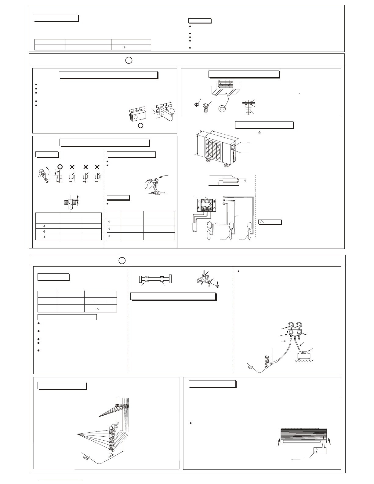
3. REFRIGERANT PIPING CONNECTION
4. WIRING CONNECTION
A
1. Cut a pipe with a pipe cutter.
Align pipes to be connected.
Sufficiently tighten the flare nut with fingers,
and then tighten it with a spanner and torque
wrench as shown.
Excessive torque can break nut depending
on installation conditions.
2. Insert a flare nut into a pipe and flare the
pipe.
2. Tightening Connection
XX
1. Remove the electric parts cover from the outdoor
unit.
2. Connect the connection cables to the terminals as
identified with their respective matched numbers
on the terminal block of indoor and outdoor units.
3. To prevent the ingress of water, make a loop of the
connection cable as illustrated in the installation
diagram of indoor and outdoor units.
4. Insulate unused cords (conductors) with PVC-tape
Process them so they do not touch any electrical
or metal parts.
1 . Do not touch the capacitor even if you have disconnected
the power for there is still high voltage power on it, or
electric shock hazard may occur. For you safety, you
should start repairing at least 5 minutes later after the
power is disconnected.
2 . The power is supplied from the Outdoor Unit. The two/three
Indoor Unit are connected with a signal wire with the
Outdoor Unit. Please make sure that the signal wires or
power cords are connected reliably and correctly, or the
air conditioner could not run normally.
CAUTION
Electrical box
Screw
Connection Cable
10mm
40mm
90 C
1. Flaring
INDOOR UNIT INSTALLATION
Prepare the power source for exclusive with the air conditioner.
The supply voltage must comply with the rated voltage of the air conditioner:
For electrical work,follow the local national wiring standard ,regulation and this installation
instructions.
Power Source
Power switch and Fuse rating
50Hz 220-240V 30A
4. Wiring
~
Perform the wiring with sufficient capacity. Installation places legally require a short circuit isolator to be attached to prevent electrical shock.
Do not extend the power cable code by cutting.
Power voltage should in the range of 90% 110% of rated voltage.
The plug of the air conditioner takes a grounding leg, so clients should use a grounding socket
so that the air conditioner can be grounded efficiently.
The power cord must be earthed reliably.
CAUTION
~
Wire Specification
2
2.5mm
OUTDOOR UNIT INSTALLATION
2
Strong
wind
1. OUTDOOR INSTALLATION PRECAUTION
Fit the seal into the drain elbow,
then insert the drain elbow into
the base pan hole of outdoor unit,
rotate 90 to securely assemble
them. Connecting the drain elbow
with an extension drain hose
(Locally purchased), in case of the
water draining off the outdoor unit
during the heating mode.
2. DRAIN ELBOW INSTALLATION
Seal
Seal
Drain elbow
Drain elbow
Base pan hole
of outdoor unit
Base pan of
outdoor unit
AIR PURGE AND TEST OPERATION
3
When Using the Vacuum Pump
Choose purge method from the table:
(L-5M) 15g
Air purging
method
Use vacuum pump
Additional amount of
refrigerant to be charged
(For how to use a manifold valve, refer to its Owner's
Manual)
1. Connect the Manifold Valve Charge Hose to the Low
Pressure Valve Charge Hole (With all the Low/High
Pressure Valves tightened)
2. Connect the Charge Hose to the Vacuum Pump.
3. Fully open the Handle Lo of the Manifold Valve.
4. Start the Vacuum pump. Slightly loose the Flare Nut of
the Low Pressure Valve to check if there is any air
leakage. (Sound of the Vacuum Pump changed and
the Compound Meter indicates "o" instead of minus).
Then tighten the Flare Nut.
5. After the evacuation is complete, full close the handle
Lo of the manifold valve and stop the operation of the
vacuum pump.
Make evacuation for 15 minutes and more and
check that the compound meter indicates -76cmHg
5
(-1.0x10 Pa).
o
6.Turn the stem of the packed valve about 45
counterclockwise for 6~7 seconds after the gas
coming out, then tighten the flare nut again.
Make sure the pressure display in the pressure
indicator is a little higher than the atmosphere pressure.
7. Remove the Charge Hose from the Low Pressure
Charge Hose.
8. Tighten the cap of the Packed Valve.
Open the valve stem until it hits against the stopper.
Do not try to open it further.
Securely tighten the valve stem cap with a spanner
or the like.
Valve stem cap tightening torque.
When relocate the unit to an other place , perform
evacuation using vacuum pump.
Perform evacuation of the two indoor units
according to the following methods.
CAUTION IN HANDING THE PACKED VALVE
Flare nut
Stopper
Cap
Valve stem
Valve body
Outdoor unit
Gas side
Indoor unit
Packed valve
Half union
Handle Lo
Charge hose
Handle Hi
Charge hose
Vacuum pump
-76cmHg
Manifold vale
Compound meter
Pressure gauge
Use vacuum pump
1. AIR PURGE
Connective
pipe length
Less than 5m
5 20m
~
Make sure no gas come out from connections with leak detector or soap water.
2. GAS LEAK CHECK
MDV03I-014aW 2200019942
COOL
Manual Button
3. TEST OPERATION
Perform test operation after completing gas leak check at the flare nut connections
and electrical safety check.
1. Connect the unit to power, then push the ON/OFF button on the Remote controller
to start the test operation.
2. Press the MODE button to check if the unit runs normally on every mode.
3. Test operation according to the following procedure when you could not find the
Remote Controller.
Open the panel, move the Manual switch on
the control panel to COOL.
4. Press COOL again after test operation. Then
installer should explain how to manipulate, fix
and maintain their air conditioner. Also tell the
clients that regular check of the installation
bracket and maintenance are necessary.
Outer diam.
(mm)
A(mm)
Max. Min.
Outer
diam.
Tightening
torque(N.cm)
Additional tightening
torque(N.cm)
6.35mm
1570
(160kgf.cm)
1960
(200kgf.cm)
9.53mm
2940
(300kgf.cm)
3430
(350kgf.cm)
3500
(400kgf.cm)
4410
(450kgf.cm)
12.7mm
6.35 1.3 0.7
9.53
1.6 1.0
12.7
1.8 1.0
Indoor unit
check point
Outdoor unit
check point
n
m
k
j
i
h
A
B
C
a
c
b
d
e
f
AUTO
Make sure to connect the indoor unit(A,B,C) to the Hi
and Lo valve and terminals of signal wires(A,B,C) of
outdoor unit as identified with their respective
matched connection. Wrong wiring connections may
cause some electrical parts to malfuntion.
CAUTION
NN
LL
Grounding
Unit B
Indoor unit B
Indoor unit A
Unit A
Wiring
Grounding
Terminal block of outdoor unit
Connective cable
of indoor unit and
outdoor unit
Connective cable
of indoor unit and
outdoor unit
Unit C
Indoor unit C
Connective cable
of indoor unit and
outdoor unit
695
31
5
845
 Loading...