

Page 1
Service Manual
Single Tub Washing Machine
Htt p://g lobal .mide a.com .cn
Note:
Bef ore ser ving th e unit, pleas e read th is at fir st,
Alw ays con tact wi h your se rvice c enter i f meet pr oblem .
Page 2
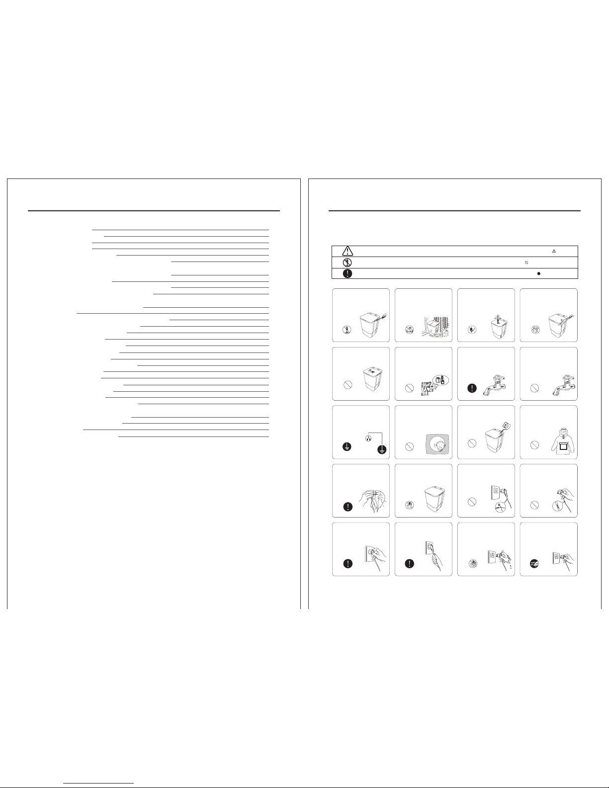
1.SAFETY PRECAUTION
-2-
1. Sa fety pr ecaut ion
2. In trodu ction o f produ ct
2.1 N ame of pa rts
3.T roub le sh ooti ng
3.1 M alfuc tion an d solut ion
3.11 . Unus ual sou nd when w ashing or wa sh
wea kly (mo tor wit h sou nd)
3.1 2. Can no t wash( motor d oes not r otate )
3.1 3. Elec tric le akage
3.1 4.Unu sual so und whe n pulsa tor rot ates
3.1 5. Wate r leak age f rom th e side o f
was h tub
3.1 6.No dr ain or un smoot h drain
3.2 F ault tr ee
3.2 1. Can no t wash (m otor do es not ro tate)
3.2 3. No dra in or uns mooth d rain
4.D isman tling w ays of ma in part s
4.1 . Remov e the kno bs
4.2 . Remov e the con trol pa nel
4.3 . Remov e the was h cover
4.4 . Remov e the pul sator
4.5 . Remov e the ove rflow c over ki t
4.6 . Remov e the fra me
4.7 . Remov e the bas e
4.8 . Remov e the mot or pull ey
4.9 . Remov e the cap acito r
5.E lectr onic co mpone nts
5.1 . Self- test me thod of w ash tim er
and w ash-d rain se lecti on swit ch
5.2 . Self- test me thod of c apaci tor
5.3 . Self- test me thod of m otor
6.C ircui t diagr am
7.E xplor ed view & l ist of pa rts
TABLE OF CONTENES
Do not s pray wa ter dir ectly t o
the ma chine .
Avoid s prayi ng wate r
Do not i nstal l the mac hine in
damp o r rainy e nviro nment t o
avoi d elect ric sho ck, fir e,
mach ine fai lure, or defo rmati on.
Avoid d ampne ss
Do not d isman tle the m achin e
by you rself .
Forbi d disma ntlin g
Do not i nsert o r unplu g the plu g
with w et hand s to avoi d elect ric
shoc k.
Forbi d wet han ds
To avoid e lectr ic shoc k
resu lting f rom ele ctric l eakag e,
plea se conn ect gro undin g wire
of the p lug pro perly.
Groun ding
Do not p lace in flamm able
mate rials l ike bur ning ca ndle,
mosq uito in cense , cigar et etc.
or hea ting so urce li ke elec tric
stov e, calo rifie r etc. on t he
mach ine.
Forbi d
W
ip
e o
ff dir t
y a
n
d d
us
t o
n t
he
plu
g o
f
t
en t
o p
re
v
en
t poor
c
o
n
t
ac
t w
i
t
h p
ower s uppl
y.
+
Do not e xceed t he max. w ater
leve l to avoi d water o verfl owing
and ma chine f ailur e.
Forbi d
+
Make s ure tha t the wat er inle t
hose i s conne cted an d the tap
is ope ned bef ore was hing.
Unpl ug the pl ug from s ocket
afte r use.
Unplu g the plu g
Do not p ut hand s into th e tub
befo re it sto pping r unnin g.
Forbi d putti ng into
D
o n
ot w
as
h c
l
ot
h
e
s th
a
t are
s
tain
e
d w
it
h ke
ro
s
e
n
e
, p
etr
o
l
,
alc
o
ho
l, a
n
d o
t
h
er fl
a
mm
a
b
l
e
s
ub
s
ta
nc
e.
Forbi d
D
o not da mage th e p
o
we
r cord
and pl u
g t
o a
v
o
i
d ele
c
t
ri
c
s
hock , s h
ort c
ir
cuit o
r fi
re.
Forbi d
D
o n
ot let b ab
y c
li
mb to th e
mach in
e o
r p
l
a
y nea
r ru
n
ni
ng
t
ub t
o a
v
oi
d a
ccid
e
nt
.
Forbi d
If use w arm wat er, the wa ter
temp eratu re shou ld not
exce ed 50℃.
Forbi d
Do not r eplac e power c ord by
your self.
Forbi d
Do not l et baby s it on it or p lace
heav y thing s on it.
Forbi d
Do not p ull the c ord whe n
unpl ug the pl ug.
Do not w ash dow n-fil led coa t,
rain coat or s imila r cloth es.
waterproo f
Forbi d
Inse rt the pl ug tigh tly whe n
use.
-1-
2
3
3
4
4
4
4
4
5
5
5
6
6
7
8
8
8
8
9
9
9
10
10
10
11
11
11
11
13
13
Be su re to com ply wit h the fol lowin g to prev ent dam age to bo dy and pr opert y of you an d
oth ers:
The s ign sta nds for “ pay att entio n” , and th e pictu re of spe cific i tems ne eds att entio n shows i n .
The s ign sta nds for “ forbi d”, and t he pict ure of sp ecifi c items f orbid den sho ws in .
The s ign sta nds for “ must do ”, and th e pictu re of spe cific i tems mu st be don e shows i n .
Page 3
SAFETY PRECAUTION
*T he dr awi ng ab ove is based on th e act ual w asher.
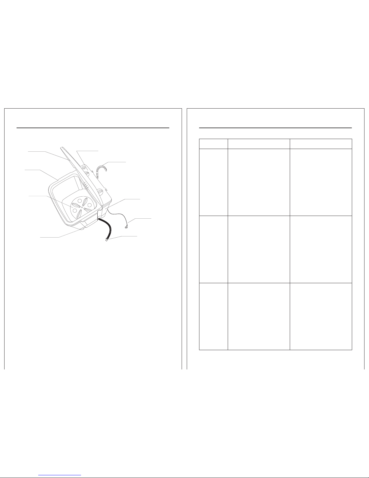
2. INTRODUCTION OF PRODUCTS
2.1 Nam e of pa rts
Sympto m
Possib le re aso n
Soluti on
1. Un usual
sou nd when
was hing or
was h weakl y
(mo tor wit h
sou nd)
a. La undry i s much mo re than r ated
was hing ca pacit y.
b. pu lsato r is tang led wit h cloth es or
blo cked by t hings l ike coi ns.
d. Pu lley br oken or p ulley s crew is
loo se .
e. Ca pacit or fail ure.
c. V-b elt loo se, bro ken or fa ll from
the s trap wh eel.
a. Re duce th e laund ry till t he
pul sator c an rota te norm ally.
b. Take o ff plu g, re move t he
pul sator a nd take o ut the
tan gled cl othes o r other t hings .
c. Re place v -belt o r reloa d the
v-b elt.
d. Re place t he pull ey or tig ht the
pul ley loc king sc rew.
e. Re place t he capa citor.
a. Po wer sup ply is cu t off or po or
con tact of p lug and s ocket .
b.
c. Wa sh tim er is i n poor c onta ct or
fau lted.
d.
e. Wa sh mot or fa ilur e.
Volt age is to o low.
Fus e is burn ed.
3. El ectri c
lea kage
a. Con ducti ve wire or alive par ts in
the mac hine co nta cts wi th me tal
cab inet.
b. Ba d earth w ire.
c. 2 po wer lin es of the p ower su pply.
d. We ak insula tion s tre ngth o f mot or
e. In sulat ion lay er of wir e harne ss is
bro ken.
a. Ch eck the p ower su pply an d
adj ust the p lug to in sure go od
con tact.
b.
c. Ch eck the w ire har ness or
rep lace th e wash ti mer.
d.
e. Re place t he wash m otor.
Do no t use the w ashin g
mac hine un til the v oltag e rise to
rat ed volt age.
Rep lace th e fuse.
a. Ch eck wir e conne cting i n the
mac hine.
b. Ch eck the e arth wi re.
c. Ex amine a nd repl ace the p ower
sup ply.
d. Re place t he moto r.
e. Ex amine t he wire h arnes s and
bin d up the br oken wi re.
2. Ca n not was h
(mo tor doe s
not r otate )
3.TROUBLE SHOOTING
3.1 Malf uct ion a nd so lution
-4--3-
Control panel
Wash cover
Pulsator
Base
Cab inet
Dra in hose
Fra me
(Fo r lower d rain on ly)
Dra in hose
(Fo r upper d rain on ly)
Pow er plug
Page 4

Sympto m
Possib le re aso n
Soluti on
3.TROUBLE SHOOTING
a. Th ere is thin gs lik e coi ns, bu tto ns
und er the pu lsato r.
b. Th e fixing sc rew be com e loos e
and t he puls ator vi brate s.
c. Ge ar in the r etard er is dam aged.
d. Ant i-loo se nuts o n the big p ulley
bec ome loo se, so th e wheel
jum ps and ma ke unus ual noi se.
e. Th e v-belt is n ot smo oth a nd
mak es nois e when ru nning o n the
pul ley.
f. Th e motor pul ley an d the b ig
pul ley is no t at a leve l.
g. No ise ins ide the w ash mot or.
a. Di smant le the pu lsato r and tak e
out t he thin gs.
b. Tig hten th e fixin g screw.
c. Re place t he reta rder.
d. Sc rew tig ht the an ti-lo ose nut s.
e. Re place t he v-be lt.
f . Adju st the mo tor pul ley to ma ke
it at t he same l evel wi th the bi g
pul ley.
g. Re place t he wash m otor.
4.U nusua l
sou nd when
pul sator
rot ates
-6--5-
a. Wa sh tub l eak s.
b. Se al ring o f the ret arder l eaks.
c. Th e overflo w hose b rak es and
wat er leak s from th e broke n place .
d. Dr ain val ve core b rakes a nd wate r
lea ks from t he valv e cover.
e. Dr ain hos e joint i s badly b ound
and w ater le aks fro m the joi nt
pla ce.
a. Re place t he wash t ub.
b. Re place t he seal r ing of th e
ret arder.
c. Re place t he over flow ho se.
d. Re place t he drai n valve c ore.
e. Di smant le drai n hose jo int and
sti ck them a gain.
5. Wa ter
lea kage fr om
the s ide of
was hing tu b
a. Wh en drai ning, t he hose i s not put
dow n and the w ater ca n not be
dra ined. (for lo wer dra in func tion
onl y)
b. Wa sh -dr ain s elec tion s witch i s
not i n “drai n”pos ition .
e. Dr ain out let is bl ocked a t the sid e
of wa sh tub.
f. Dr ain fal ls from t he swit ch.
g. Dr ain bel t is loos ened or b roken .
c. Dr ain out let is no t laid pr operl y.
(fo r upper d rain fu nctio n only)
d. Dr ain pum p failu re
( for u pper dr ain fun ction o nly).
bel t
a. Pu t down th e drain h ose and
mak e the hos e mouth t o the
sew er.
c. Th e drain hos e shou ld be p lace d
86 cm -100c m from th e botto m of
the g round .
e. Di smant le the pu lsato r and tak e
out t he bloc ks at the d rain ou tlet .
f. Co nnect t he drai n wit h the
swi tch.
g.R eplac e the dra in belt .
b. Tur n the swi tch to “d rain” p ositi on
d. Re place t he pump o r open th e
val ve cove r to clea r up the pu mp.
bel t
6. No d rain or
uns mooth d rain
Can n ot wash
Y
Y
N
N
N
Y
Y
Y
N
N
Whe ther th e power
sup ply is we ll
Che ck the po wer sup ply
Whe ther th e plug
is co ntact
Adj ust the p lug to in sure
goo d conta ct
Whe ther th e volta ge
is co rrect
Wait t he volt age to ri se
to co rrect v oltag e
Whe ther th e wash
tim er is wel l
Y
N
Rep lace th e wash ti mer
Whe ther th e fuse
is we ll
Rep lace th e fuse
Whe ther th e capac itor
is we ll
Rep lace th e capac itor
Y
N
Whe ther th e wash
mot or is wel l
Rep lace th e wash mo tor
3.TROUBLE SHOOTING
1. Ca n not was h (moto r does no t rotat e)
3.2 Faul t tre e
Page 5

-8--7-
3. No d rain or u nsmoo th drai n
Can n ot drai n
Y
Y
N
N
N
Y
Y
Y
N
N
Whe ther th e drain
hos e is put do wn
Put d own the d rain ho se
Whe ther th e washdra in sele ction s witch i s
not i n “drai n”pos ition
Whe ther th e drain
hos e is laid p roper ly
Whe ther th e drain
pum p is well
Y
N
Rep lace th e drain p ump
Whe ther th e drain
hos e at the si de of
was h tub is bl ocked
Dis mantl e the pul sator
and t ake out t he bloc ks
in th e water d rain ho se
Whe ther th e drain
bel t is on the s witch
Han g the dra in
bel t onto th e switc h
Y
N
Whe ther th e drain
bel t is well
Rep lace th e drain b elt
Turn t he swit ch to “dr ain”
pos ition
The d rain ho se shou ld be
pla ced 86c m-100 cm from
the b ottom o f the gro und
for l ower dr ain fun ction o nly
for u pper dr ain fun ction o nly
for u pper dr ain fun ction o nly
3.TROUBLE SHOOTING 4.DISMANTLING WAYS OF MAIN PARTS
1. Remov e the k nob s
a.Take out the knobs dire ctly
because knob s are in ser ted
int o the con trol pa nel.
b. If i t is diff icul t to take k nobs ou t,
a str aight s crew drive r wrappe d
with clo th can be use d for he lp.
Operation step
Picture
a.
b.
2. Remov e the c ont rol p anel
a. Take dow n the back co ver by
loo sen-i ng off th e screw s.
b. Take dow n the plastic bag by
cuttin g off the nyl on clip. Take
down all wi re nut wit h a pli er
and make all w ire clamps loose.
and then unfasten the dr ain belt
connec tor.
c. Scr ew off th e scre ws on the
con trol pa nel.
d. Th e contr ol pane l can be li fted
and r emove d.
a. b.
c.
d.
a.
3. Remov e the w ash c ove r
a
dra w out the w ash cov er with
the h elp of a sc rew-d river .
. Kee p the was h cover o pen and
Page 6

-10 --9-
4.DISMANTLING WAYS OF MAIN PARTS
Operation step
a.
4. Remov e the p uls ato r
a. the p ulsat or scre w.
b. Dr aw out th e pulsa tor wit h
han ds.
Scr ew off
Picture
b.
a.
5. Remov e the o ver flo w cover
kit
a.H old the
the n pull it o ut.
overfl ow co ver k it
a. b.
6.Remo ve th e fra me
a. Sc rew off t he scr ews of th e
fra me.
b. Th e frame c an be rem oved.
4.DISMANTLING WAYS OF MAIN PARTS
Operation step
Picture
a.
a.
9. Remov e the m oto r pul ley
a.L oosen t he nut wi th spec ial
wre nch,t hen loo sen the s crew.
10. Remo ve th e cap aci tor
a.H old fir m the cap acito r then
pul l it out.
a.
b.
8. Remov e the b ase
a. Pr ess the V-be lt at the par t near
the pull ey. Then t ake do wn th e
V-be lt by rot ating t he pull ey.
b. Spr ead one bl anket on the
floor th en lay down the wash ing
machine. Pul l out the drain hose
from the cl amp and dr aw out the
drain ho se subassem bly. Af ter
screws on the base a re
uns crewe d, the ba se asse mbly
can b e disas sembl ed.
Page 7

-12 --11-
5.ELECTRONIC COMPONENTS
Operation step
Picture
1. Self- tes t met hod o f wash
timer an d
Turn th e wash tim er to work
condi tion . Use a multime ter to
mea sure th e conne ction a nd
di scon nect ion c ond iti on o f
in put t erm ina l(b rown w ire) a nd
out put ter minal ( yello w or oran ge
wir e), and t he wash t imer sh ould
be re gular o n-off .
wash-d rai n
select ion s wit ch
Use a m ulime ter to me asure t he
sel ectio n switc h, the sw itch
sho uld be re gular o n-off .
5.ELECTRONIC COMPONENTS
2. Self- tes t met hod o f capacit or
Use an analog multimeter to measure
capacitance by connecting t he t wo
ends of capacitor with the multim eter
rod connecto r . If the pointer swi ng
to the direction of smaller
resistance ,and then turn back to
the dir ectio n of “0” slowly, it means
that the capacitor is ok . If not , it
mea ns that t he capa citor i s
fau lted.
3. Self- tes t met hod o f motor
a. To check wheth er the mo tor
in sul ati on i s da mag ed b y
wa ter le aka ge:
Use a 500 V megohmmet er to
measure whe ther the insu lation
resista nce of motor is higher than
30MΩ At th e same ti me, che ck
whe ther th e other r esist ance of
the m otor ar e norma l. If the
oth er resi stanc e are abn ormal
(an y short-circuit, open circuit
appears), the mo tor c an not be
used. Only the two items are
normal, the motor can b e used .
.
Operation step
Picture
b. Check whether the motor
resistance is normal i n the
condit ion o f no wa ter
condit ion :
Use a m ultim eter to m easur e the
res istan ce of the three leads, and
name them R1, R2, R3
.On ly the
“R1 +R2=R 3” indicates that the
motor resistance is normal.
(th e max.
one n ame R3)
c. Check t he mo tor o per ation
condit ion :
For the motor under
use, add certain 20 # machine oil on
the upper and down bearing to
eliminate the negative effect arisin g
from water leakag e.After pow ering
on the two component s, ther e
sho uld be no o bviou s noise ,
vib ratio n,or od or of the m otor.
Use power cab le with fuse to
connect the motor a nd capacito r
correctl y, and do the prepara tion
for i nsula tion.
Page 8

-14 --13 -
6.CIRCUIT DIAGRAM
Circuit diagram
Black
Brown
Fuse
Yellow
/Green
Brown
Light blue
Red
Wash motor
C1
M1
Green
Red
Yellow
Yellow Yellow
Yellow
Wash timer
7.EXPLORED VIEW & LIST OF PARTS
1 Control Panel Assembly
2 Twin-tub Assembly
3
/
4 Base Assembly
1
4
2
Circuit diagram
Abo ve Circ uit Dia gram is o nly for r efere nce, an d the sta ndard C ircui t Diagr am is
acc ordin g to the ra ting la bel of co mplet e machi ne.
Page 9

-16 --15 -
7.EXPLORED VIEW & LIST OF PARTS
1.1
/
1.2
/
1.3
/
1.4
/
1.5
/
1.6
/
1.7
/
1.8
/
1.9
/
1.1O
/
1.11
Top Frame
1.12
/
1.13
/
1.14
/
1.15
Wash Cover Kit
1.16 Wash Timer
1.17 Control Panel
1.18 /
1.19 Knob
1.17
1.15
1.11
1.19
1.5
1.16
7.EXPLORED VIEW & LIST OF PARTS
2.3.1 Overflow Cover
2.3.2 Lint Filter
2.4 Back Cover
2.5 Drain Pipe
2.6 Retarder kit
2.7 Drain Valve K it
2.8 Bottom Valve
2.9 Anti-vibration Ring
2.1O Rubber Washer
2.11 B rake Block
2.12 Twin-tub
2.13 Flas hing
2.14 P ulsator Screw Kit
2.14
2.1
2.3.1
2.3.2
2.4
2.5
2.12
2.8
2.6
2.13
2.5
2.3
Page 10

-18 --17 -
7.EXPLORED VIEW & LIST OF PARTS
4.1
V-belt
4.2
Small Pulley
4.3
Wash Motor
4.4.1
Specific Screw for Wash Motor
4.4.2
Specific Washer
4.4.3
Rubber (upper)
4.5
Rubber (lower)
4.6
Base
4.7
/
4.8
Wire
4.9
/
4.1O
/
4.11
/
4.12
/
4.13
/
4.14
/
4.1
4.2
4.3
4.4.2
4.5
4.6
4.8
4.4.1
4.4
 Loading...