

Page 1
INSTALLATION MANUAL AND
OPERATING INSTRUCTIONS
MODEL MD302-( ) SERIES
STANDBY ATTITUDE MODULE
Mid-Continent Instrument Co., Inc.
dba Mid-Continent Instruments and Avionics
Manual Number 9017782
Rev B, October 31, 2012
Page 2

Mid-Continent Instruments and Avionics, Wichita, KS
FOREWORD
This manual provides information intended for use by persons who, in accordance with current regulatory
requirements, are qualified to install this equipment. If further information is required, please contact:
Mid-Continent Instruments and Avionics
Attn: Customer Service Dept.
9400 E. 34
Wichita, KS 67226 USA
We welcome your comments concerning this manual. Although every effort has been made t o keep it
free of errors, some may occur. When reporting a specific problem, please describe it briefly and include
the manual part number, the paragraph /figure/table number, and the page number. Send your
comments to:
Mid-Continent Instruments and Avionics
Attn: Customer Service Dept.
9400 E. 34
Wichita, KS 67226 USA
th
St. N.
th
St. N.
©
Copyright 2012
Mid-Continent Instrument Co., Inc.
REV. B, October 31, 2012 2 Manual Number 9017782
Page 3

Rev
Date
Approved
Detail
1
09/10/12
BAW
Engineering release.
A
10/02/12
BAW
Initial release.
B
10/31/12
BAW
Updates implemented.
Mid-Continent Instruments and Avionics, Wichita, KS
REVISION HISTORY
REV. B, October 31, 2012 3 Manual Number 9017782
Page 4

Mid-Continent Instruments and Avionics, Wichita, KS
Table of Contents
SECTION 1 GENERAL DESCRIPTION 6
1.1 INTRODUCTION 6
1.2 SYSTEM OVERVIEW 7
1.2.1 PRE-FLIGHT MODE ................................................................................................. 7
1.2.2 FLIGHT MODE ........................................................................................................ 7
1.2.3 EMERGENCY MODE ................................................................................................. 9
1.2.4 CONFIGURATION MODE .......................................................................................... 9
1.3 TECHNICAL SPECIFICATIONS 10
1.3.1 ELECTRICAL ATTRIBUTES ..................................................................................... 10
1.3.2 PHYSICAL ATTRIBUTES ......................................................................................... 10
1.3.3 PERFORMANCE LIMITS.......................................................................................... 10
1.3.4 QUALIFICATIONS ................................................................................................. 10
SECTION 2 INSTALLATION 12
2.1 GENERAL INFORMATION 12
2.2 PARTS LIST 12
2.3 EQUIPMENT LOCATION 12
2.4 LIMITATIONS 14
2.5 CABLE HARNESS 15
2.5.1 WIRE GAUGE SELECTION ...................................................................................... 15
2.5.2 CONFIGURATION MODULE .................................................................................... 15
2.6 PITOT / STATIC CONNECTIONS 18
2.7 MOUNTING 18
2.8 INSTALLATION COMPLETION 18
SECTION 3 OPERATION 21
3.1 USER INTERFACE 21
3.2 PRE-FLIGHT MODE 21
3.3 FLIGHT MODE 22
3.3.1 MAJOR FUNCTIONS .............................................................................................. 23
3.3.1.1 ATT I TUDE OPERATION ......................................................................................... 23
3.3.1.2 ALTITUDE OPERATION .......................................................................................... 24
3.3.1.3 AIRSPEED OPERATION .......................................................................................... 25
3.3.1.4 SLIP OPERATI ON .................................................................................................. 26
3.3.2 OPTION SETTINGS ............................................................................................... 27
3.3.2.1 MENU OPERATIO N ................................................................................................ 27
3.3.2.2 ALT UN I TS ........................................................................................................... 28
3.3.2.3 BARO UN I TS ........................................................................................................ 28
3.3.2.4 SYMBOL............................................................................................................... 28
3.3.2.5 ATT MASK ............................................................................................................ 29
3.3.2.6 ALT TR EN D .......................................................................................................... 29
3.3.2.7 POWER OFF ......................................................................................................... 30
3.3.2.8 REVIEW CONFIG .................................................................................................. 30
3.3.2.9 EXIT MENU .......................................................................................................... 31
3.3.3 BRIGHTNESS ADJUSTMENT ................................................................................... 31
3.4 EMERGEN CY OP ER AT IO N 31
3.4.1 IN FLIGHT ........................................................................................................... 31
3.4.2 ON THE GROUND ................................................................................................. 32
REV. B, October 31, 2012 4 Manual Number 9017782
Page 5

Mid-Continent Instruments and Avionics, Wichita, KS
SECTION 4
CONFIGURATION SETUP 33
4.1 CONFIGURATION MODE/MENU 33
4.2 CONFIGURE DISPLAY 34
4.2.1 ROLL DISPLAY ...................................................................................................... 35
4.2.2 AIRSPEED UNITS .................................................................................................. 35
4.2.1 DISPLAY ORIENTATION ........................................................................................ 36
4.3 CONFIG DIMMING 36
4.3.1 DIMMING CONTROL.............................................................................................. 37
4.3.2 DIMMING CURVE .................................................................................................. 37
4.4 CONFIGURE AIRCRAFT 38
4.4.1 PANEL TILT .......................................................................................................... 39
4.4.2 RANGE MMO ........................................................................................................ 39
4.4.3 RANGE MARKINGS ................................................................................................ 40
4.5 CONFIGURATION MODE ACTIONS 41
4.5.1 UPDATE SOFTWARE.............................................................................................. 41
4.5.2 ARINC SPEED ....................................................................................................... 41
4.5.3 ACCEPT CHANGES ................................................................................................ 42
4.5.4 CANCEL CHANGES ................................................................................................ 42
SECTION 5 CONFORMANCE 43
5.1 INSTRUCTIONS FOR CONTINUED AIRWORTHINESS 43
5.1.1 PRESSURE SYSTEM AND ALTIMETER VERIFICATION ................................................ 43
5.1.2 SOFTWARE UPGRADES.......................................................................................... 43
5.1.3 BATTERY REPLACEMENT ....................................................................................... 43
5.1.4 TROUBLESHOOTING ............................................................................................. 43
5.2 ENVIRONMENTAL QUALIFICATION STATEMENT 47
REV. B, October 31, 2012 5 Manual Number 9017782
Page 6

Mid-Continent Instruments and Avionics, Wichita, KS
SECTION 1 GENERAL DESCRIPTION
1.1 INTRODUCTION
The model MD302 series Standby Attitude Module is a self-contained situational awareness instrument
that provides aircraft attitude, altitud e, airspeed and slip indication. The compact and innovative design
of the MD302 is specifically developed for maximum flexibility for installation in retrofit or modern
instrument panel. Its size, extra-wide viewing angle and AnyWay selectable orientation allows it to be
installed almost anywhere in the instrument panel and in less space than trad iti on al 2-inch mechanical
standby or primary flight instruments.
Regardless of the aircraft you’re f lying, the MD302 is a great fit. With a 10 to 32 volt DC input range, the
unit w ill work with 14 o r 28V aircraft electrical buses and the selectable lighting input allows operation
with 5, 14 or 28V lighting systems. The operation and certification of the MD302 make it well su ited for
Part 23 and 25 fi xe d-wing applications as well as Part 27 and 29 rotorcraft.
The MD302 provides critical flight an d situational data to the pilot and crew under any circumstances
you’re likely to encounter. The design is built around a solid-state electronic sensor array for high
reliability and contains an integral and rechargeable Nanophosphate
the unit for up to two hours if main aircraft power is lost. The dual, high-resolution LCD display uses
smooth graphics, daylight-readable brightness, and a configurable lighting response curve to ensure
optimal visibility in all conditions.
The user interface of the product allows for simple, intuitive operation using a single push-and-turn knob
that easily navigates through the user options and menu screens. The interactivity of the unit means that
it can receive and transmit ARINC 429 data communications. Functional outputs of attitude, altitude, and
airspeed can be used for monitoring or backup information while baro input data can be received that will
synchronize the baro setting with the primary system to eliminate redundant task loading for the pilot.
The MD302 is an excellent complement to your avionics suite as a reliable and state-of-the-art instrument
that is an essential part of any instrument panel.
®
lithium-ion battery that can power
REV. B, October 31, 2012 6 Manual Number 9017782
Page 7
Mid-Continent Instruments and Avionics, Wichita, KS
1.2 SYSTEM OVERVIEW
The MD302 has four specific modes of operation. They are:
• Pre-flight Mode
• Flight Mode
• Emergency Mode
• Configuration Mode
The following sections will briefly introduce each mode with further details provide within Sections 3 and
4 of this manual.
1.2.1 PRE-FLIGHT MODE
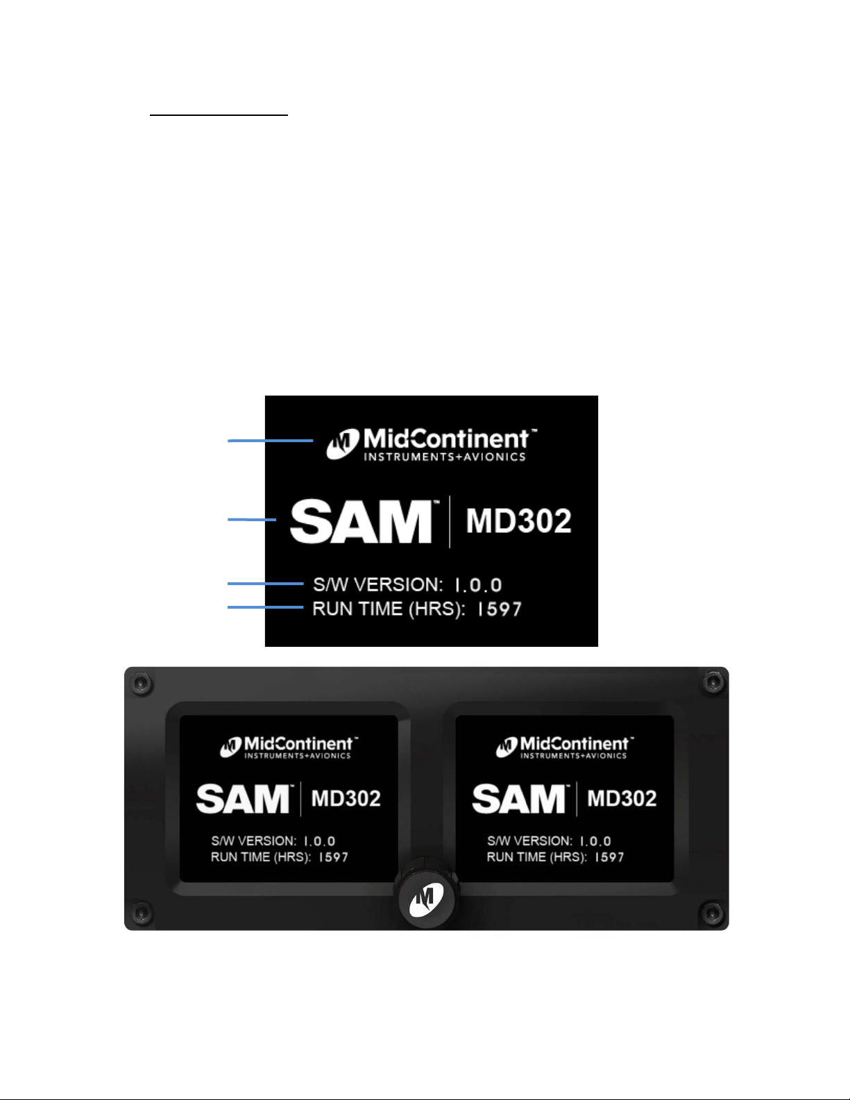
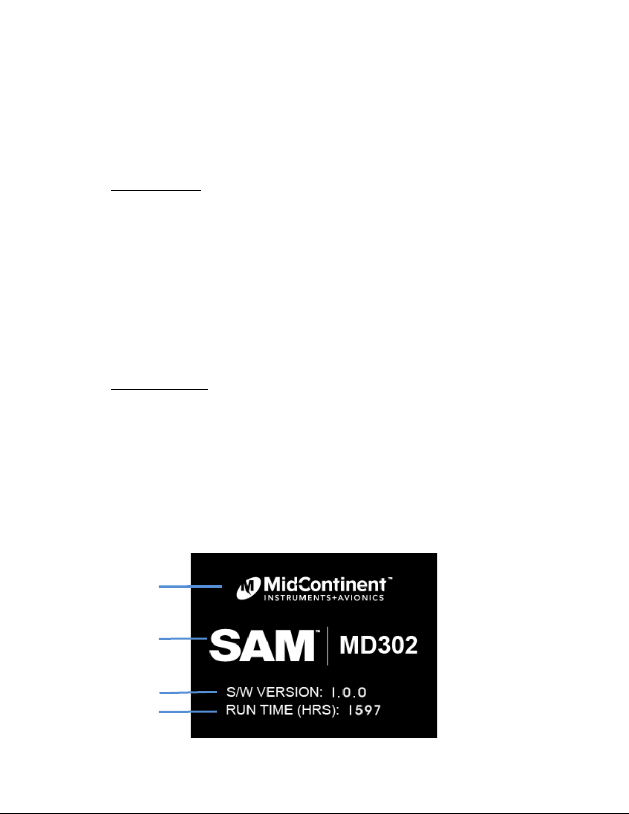
In Pre-flight Mode, power is applied to the unit and the introduction screen appears
during startup with the information shown in Figure 1.1.
manufacturer’s logo
model name/num b er
software version
total operating time
FIGURE 1.1
1.2.2 FLIGHT MODE
REV. B, October 31, 2012 7 Manual Number 9017782
Page 8
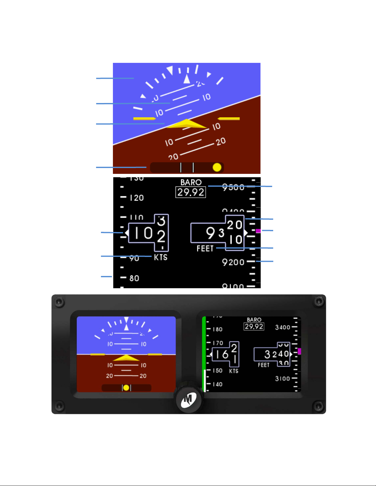
barometer value
altitude trend bar
altitude window
altitude units
altitude tape/scale
Mid-Continent Instruments and Avionics, Wichita, KS
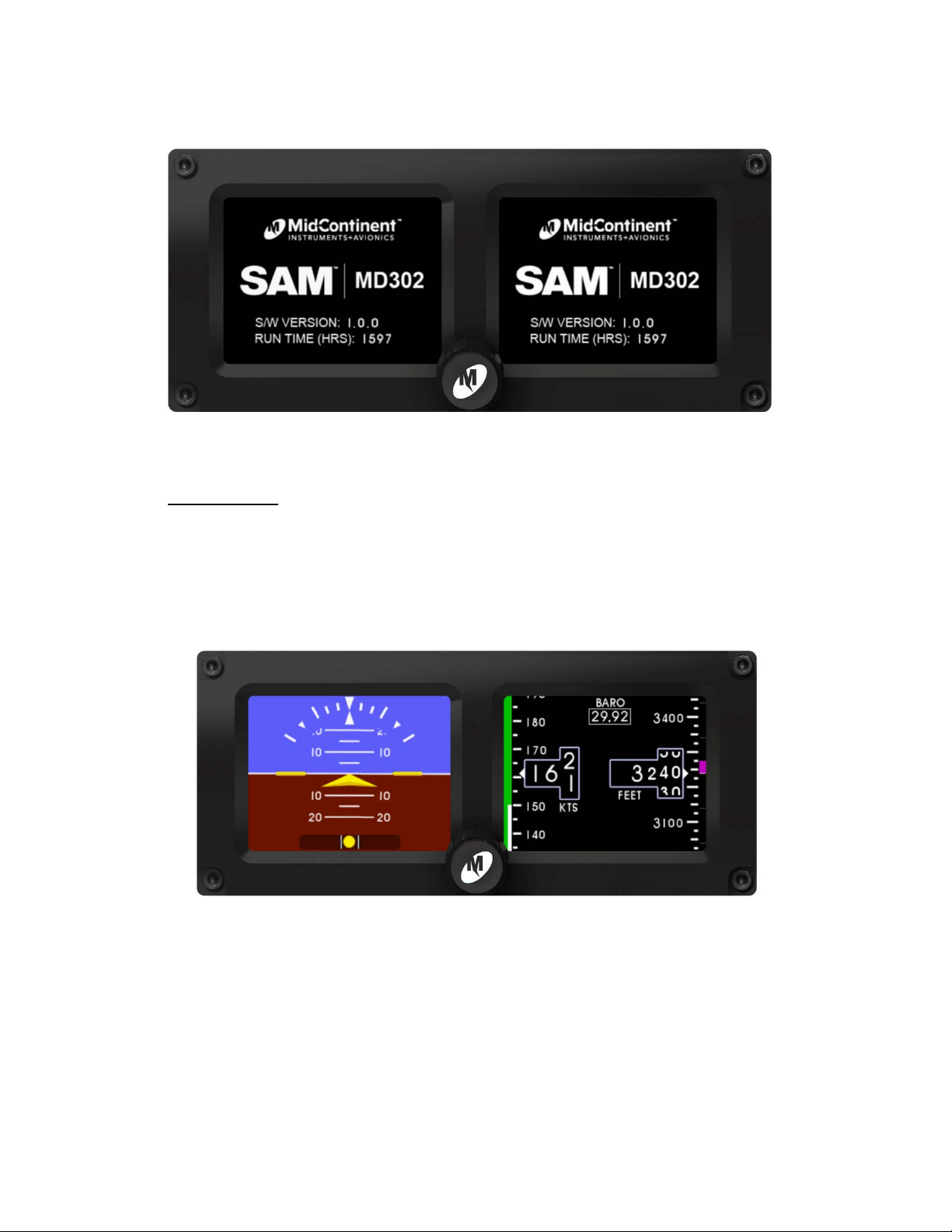
In Flight Mode, the unit operates normally by displaying attitude, altitude, airspeed and
slip information as shown in Figure 1.2.
roll/bank scale
pitch scale
symbolic airplane
slip indicator
airspeed window
airspeed u nit s
airspeed tape/scale
Figure 1.2
FIGURE 1.2
REV. B, October 31, 2012 8 Manual Number 9017782
Page 9
battery icon
Mid-Continent Instruments and Avionics, Wichita, KS
1.2.3 EMERGENCY MODE
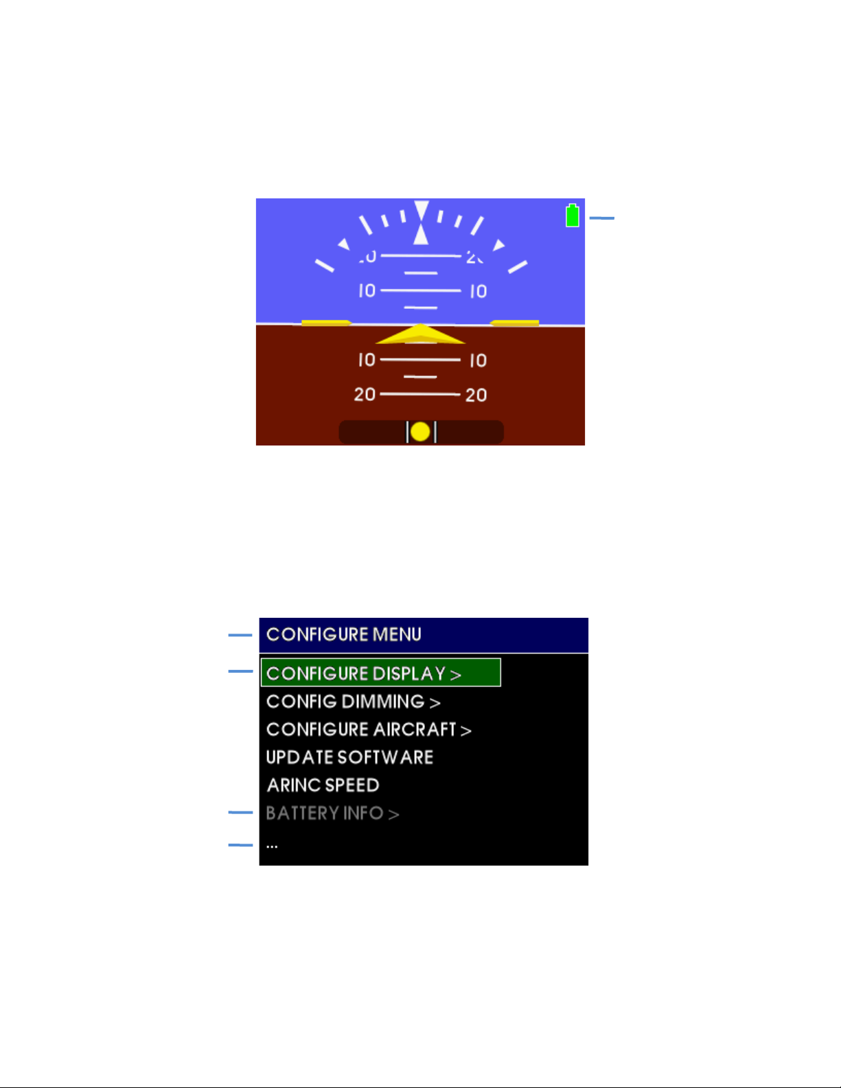
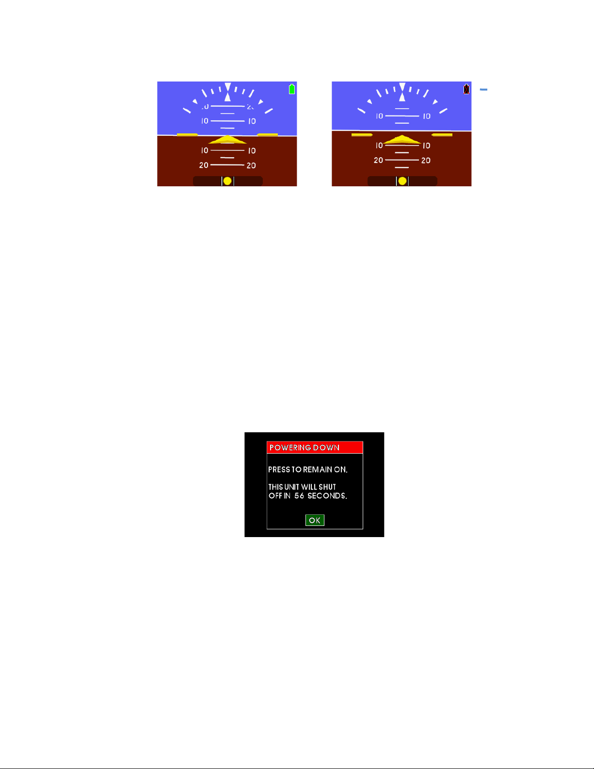
In Emergency Mode, aircraft power to the instrument has been lost and the unit
continues to operate in Flight Mode utilizing power from the internal battery. The battery
icon is displayed as shown in F igure 1.3.
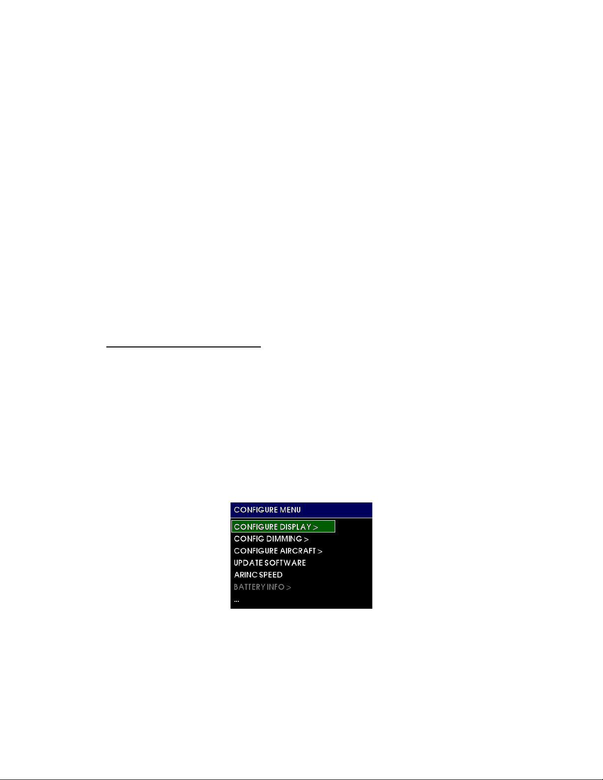
1.2.4 CONFIGURATION MODE
In Configuration Mode, an auth orized installer can change and set th e ap p r opriate
configuration values that are specific to the aircraft. These also include user preferences
that are not available during flight an d certain maintenance functions as well. The top
level menu in Configuration Mode is shown in Figure 1.4.
current menu
current selection
unavailable
more optio ns available
FIGURE 1.3
FIGURE 1.4
REV. B, October 31, 2012 9 Manual Number 9017782
Page 10

Characteristics:
Input Voltage:
10-32 VDC
Input Power: (nominal)
4 watts (0.15A @ 28VDC)
(maximum)
25 watts max (when charging and heating battery)
Lighting Input:
5.14, or 28VDC or automatic photocell control
Input Data:
barometer synchronization via ARINC 429 (see Table 1. 5)
Output Data:
attitude, altitude, airspeed via ARINC 429 (see Table 1.5)
discrete valid signal to groun d; invalid signal is open (pin 2)
Characteristics:
Weight:
1.6 pounds (0.73 kg)
Dimensions:
Bezel: 2.37” x 5.50” x 0.33” (HxWxD)
Mating Connectors:
15-pin D-Sub with Configuration Module, MCIA p/n 9017275
Pneumatic fittings, MCIA p/n 9017642
Mounting:
Panel mount from front; uses (4) #6-32 cap screws and
MCIA p/n 90174 90 -2 Nutplate (included)
Characteristics:
Attitude: Pitch Angle
No limits (360°+)
Pitch Rate
300° per second max
Roll Angle
No limits (360°+)
Roll Rate
300° per second max
Altitude: Range
-1,500 to +55,000 feet (available in meters)
Barometer
28.00 to 31.00 in ches of mercury (avai lab le in inHg /mB/hPa)
Air Speed: Range
20 to 500 knots (available in mph or kph)
Specifications:
Certifications: (PENDING)
FAA TSO-C2d (Type B), C3e, C4c, C10b, C106, C113a, C179a
Environ menta l Q ualification:
RTCA DO-160G Environmental Category
(F1)(S2)AB(RBB1)XXXXXXZ(ZXX)AZ(ZC)[WF]P[B3H33]XXAX
Software Qualification:
RTCA DO-178B, Design Assurance Level A
Complex Hardware Qualification:
RTCA DO-254, Design Assurance Level A
Mid-Continent Instruments and Avionics, Wichita, KS
1.3 TECHNICAL SPECIFICATIONS
1.3.1 ELECTRICAL ATTRIBUTES
1.3.2 PHYSICAL ATTRIBUTES
TABLE 1.1
(without connectors, mates, & knob)
1.3.3 PERFORMANCE LIMITS
1.3.4 QUALIFICATIONS
Chassis: 2.31” x 3.16” x 4.8 2” (HxWxD)
TABLE 1.2
TABLE 1.3
REV. B, October 31, 2012 10 Manual Number 9017782
TABLE 1.4
Page 11
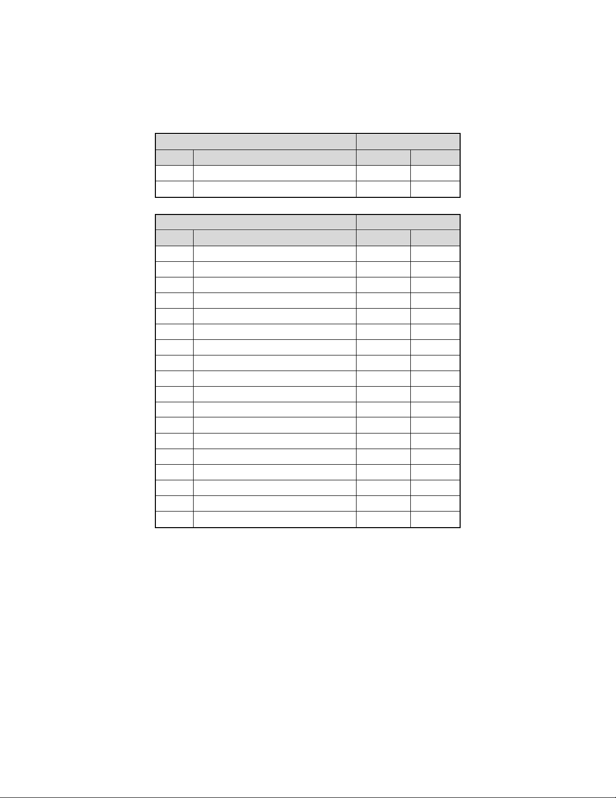
ARINC 429 Input
Speed
Label
Description
High
Low
203
altitude (rel 29.92)
x
x
204
baro altitude
x x ARINC 429 O utput
Speed
Label
Description
High
Low
203
altitude (rel 29.92)
x
x
204
baro altitude
x
x
212
altitude rate
x
x
215
impact pressure
x
x
217
static pressure
x
x
324
pitch attitude
x
x
325
roll attitude
x
x
326
body pitch rate
x
327
body roll rate
x
330
body yaw rate
x
331
body longitudinal acceleration
x
332
body lateral acceleration
x
333
body normal acceleration
x
336
inertial pitch rate
x
337
inertial roll rate
x
340
inertial yaw rate
x
364
vertical acceleration
x
377
specific equip ment id
x
x
Mid-Continent Instruments and Avionics, Wichita, KS
ARINC DATA LABELS
All labels are defined as Equipment ID 038 in BNR format.
High and Low speed options are configurable. See Section 3.4.
REV. B, October 31, 2012 11 Manual Number 9017782
TABLE 1. 5
Page 12

Mid-Continent Instruments and Avionics, Wichita, KS
SECTION 2 INSTALLATION
2.1 GENERAL INFORMATION
IMPORTANT: READ THIS ENTIRE SECTION PRIOR TO STARTING INS T A L L A TION!
This section contains interconnect diagrams, mounting dimensions and other information pertaining to
the installation of the MD30 2D ig it al Flig h t Instrument. After installation of cabling and bef ore installation
of the equipment, ensure that power is applied only to the pins specified in the interconnect diagram.
2.2 PARTS LIST
When unpacking this equipment, make a visual inspection for evidence of any damage that may have
incurred during shipment. The following parts should be included:
Item Description MCIA Part Number
a. MD302 Digital Flight Instrument 6420302-( )
b. Installation Manual – 9017782
c. Connector Kit – 9017646
i. Nutplate 9017490-2
ii. Pneumatic Connector (x2) 9017642
iii. Screw, Hex, 6-32x5/8 (x4) 90-620-52011
iv. Screw, Flat, 2-56x1/4 (x2) 90-208-10011
v. Configuration Module 9017275
1. 15-pin D-Sub
2. Backshell
3. Backshell Cover
4. Printed Circuit Board Assembly
5. Screw, Flat, 2-56x1/4 (x2)
6. Screw, 4-40x3/16 (x4)
2.3 EQUIPMENT LOCATION
The MD302 Standby Attitude Module is designed primarily to be installed in the instrument panel of the
aircraft. However, within the limitations of the environmental qualifications, other locations may be
acceptable when considered within the context of the specific application and with the appropriate
installation certification.
The MD302 has an extra wide viewing angle and AnyWay™ selectable orientation that allows for flexible
installation locations and option s. The unit can be mounted vertically (knob left or knob right) or horizontally.
Once installed, the display orientation can be selected to match the installation. See Figure 2.1. However, be
sure to consider appropriate field-of-view in regards to pilot and/or co-pilot vis i bility an d accessibility when
selectin g a location to install the MD302. Note: when installing in vertical orientation, choose the knob
position based on whether or not the pilot’s hand will obscure the display during operation.
Additionally, consider what equipment is behind the panel which may impede the installation of the
MD302. Clearance for the unit as well as its electrical and pneumatic connections and routing must be
allowed. Be aware of routing cables near other electronics or with other wire bundles that may be
susceptible to high energy flow. Avoid sharp bends in cabling or hoses and routing near aircraft control
cables. Also avoid proximity and contact with aircraft str uctures, avionics equipment, heat sources or
other obstructions that could chaf e or damage wires or hoses during flight and cause undesirable effects.
No external cooling is required.
REV. B, October 31, 2012 12 Manual Number 9017782
Page 13
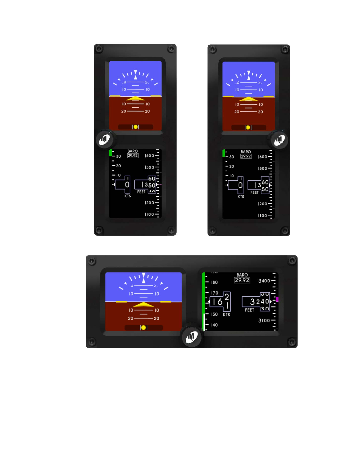
Mid-Continent Instruments and Avionics, Wichita, KS
INSTALLATION ORIENTATION OPTIONS
FIGURE 2.1
REV. B, October 31, 2012 13 Manual Number 9017782
Page 14

Mid-Continent Instruments and Avionics, Wichita, KS
2.4 LIMITATIONS
The conditions and tests for TSO approval of this article are minimum performance standards. Those
installing this article, on or in a specific type or class of aircraft, must determine that the aircraft
installation conditions are within th e TSO standards, specification of the ar ticle, and deviations as listed
above. TSO articles must have separate approval for installation in an aircraft. The article may be
installed only according to 14 CFR part 43 or the applicable airworthiness requirements.
There are some porti ons of these TSOs which do not apply to our product or represent out dated
requirements. These items are highlight ed below and hav e been submitted to and approved by the FAA
as deviations to t he TSO certifications of the product.
FAA TSO-C2d: Airspeed Instruments
• instrument is not labeled wit h “Airspeed” or “IAS”
FAA TSO-C3e: Turn and Slip Instrum ent
• instrument does not provi de r ate-of-turn functionality
FAA TSO-C4c: Bank and Pitch Instruments
• dielectric strength/insulation resi stanc e does not apply due to electronic components between
chassis and connector pi ns
FAA TSO-C10b: Altimeter, Pressure Act uated, Sensitive Type
• graduation increm ents are every 25 feet instead of 20 feet
FAA TSO-C179a: Permanently Installed Rechargeable Lit hium Cells, Batteries and Batter y System s
• dielectric strength/insulation resi stanc e does not apply due to electronic components between
chassis and connector pi ns
REV. B, October 31, 2012 14 Manual Number 9017782
Page 15
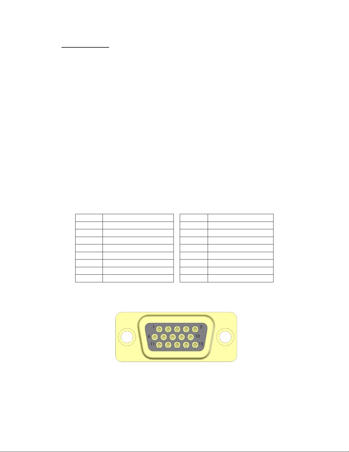
15-pin D-Sub Connector
Pin No.
Description
Pin No.
Description
1
+10-32VDC Input
8
ARINC Out A
2
Valid Signal Ou t
9
Reserved
3
ARINC Out B
10
Config Module Clock
4
Reserved
11
Reserved
5
Config Module Power
12
ARINC In A
6
Power Return / Ground
13
ARINC In B
7
Lighting Bus Input
14
Config Module Data
15
Config Module Return
TABLE 2.1
Mid-Continent Instruments and Avionics, Wichita, KS
2.5 CABLE HARNESS
Construct the cable harness with regards to the instructions below and using the Connector Pinout of
Table2.1 and Figure 2.2 and Configuration Module Assembly of Figure 2.3. Installers should follow
industry-accepted practices regarding aircraft wiring and applicable regulatory and advisory requirements
and guidance.
Refer to Section 2.3: Equipm ent Location in regards to routing precautions.
2.5.1 WIRE GAUGE SELECTION
Wire gauge should be 22 AWG. Use of PTFE, E TF E, TF E, Tef lon , or tef ze l insulated wire
is recommended for aircraft use per MIL-DTL-16878 or equivalent for the connections as
noted below. Additionally, for data signals associated with ARINC 429 inputs and outputs,
shielded twisted pair wiring per M27500 or equivalent is recommended (pin pairs 3/8 and
12/13).
2.5.2 CONFIGURATION MODULE
The supplied custom configuration module is required for proper installation and
operation of the MD302 unit. The functions associated with the 15-pin D-subminiature
connector are identified as follows:
REV. B, October 31, 2012 15 Manual Number 9017782
VIEW FROM RE AR OF MATING CONNECTOR
FIGURE 2.2
Page 16

Mid-Continent Instruments and Avionics, Wichita, KS
To assembly the aircraft cable harness and Configuration Module refer to the following
instructions and Figure 2.3:
1) Install a pin/socket as supplied in the Connector Kit using an appropriate crimping tool for
each wire in the aircraft cable harness. Be sure to make the harness long enough to rem ove
the unit from the front of the panel without stressing the harness (approx. 8” longer than
required to reach the unit connector).
2) Braids from shielded wires should separate from the wire conductors and pulled back from
the pin/socket termination appr oximately 2” and gathered together.
a. NOTE: Additional chafe protection, such as heat shrink or nylon wire braid is
recommended over the bundle (not including the shields) to prevent wear when
installed in the cable clamp.
3) Insert the pins of the cable harness into the rear of the 15-pin D-Sub connector (Item 4) per
Table 2.1 and Figure 2.2using an appropriate pin insertion tool.
NOTE: The Configuration Module PC Board Assembly contains sensitive electronics that can be
damaged by electrostatic discharge (ESD). Appropriate precautions should be applied prior to
handling this component.
4) Insert the pins of the Configuration Module PC Board Assembly (Item 3) into their
corresponding locations as noted below using an appropriate pin insertion tool.
a. The wires coming from the Configuration Module PC Board Assembly are marked as
follows on the circuit board: TP1, TP2, TP3, TP4.
b. With the D-Sub oriented up (pin locations 1-5 on top), orient the Configuration
Module PC Board Assembly with the electronic parts facing UP prior to pin insertion.
c. Install each pin into the rear of the D-Sub connector as follows:
• TP1 = config return = pin 15
• TP2 = config data = pin 14
• TP3 = config clock = pin 10
• TP4 = config power = pin 5
5) Install the D-Sub Backshell Spring (Item 5) as shown.
6) Place the D-Sub Slide Lock (Item 6) over the D-Sub connector.
7) Install the D-Sub connector with Slide Lock and cable harness attached into the Backshell
(Item 9) and secure with (2) screws (Item 8). Verify that the Backshell Spring is between
the Slide Lock and Backshell. Move the Slide Lock back and forth to verify free movement.
8) Route the aircraft wire harness bundle (excluding shield braids) between the two halves of
the Cable Strain Relief Clamp (Item 7). The Clamp should be placed over the chafe
protection installed in Step 2 (if used).
9) Loosely connect the two halves of the Cable Strain Relief Clamp with (2) screws (Item 8).
10) Place the Cable Strain Relief Clamp in the Backshell as shown.
11) Bend the wires of the Configuration Module PC Board Assembly 180 degrees so that the PC
Board has its electrical componen ts facing down as shown. Be careful not to place excess
strain on the solder connections between the wires and the PC Board.
12) Capture the Configuration Module PC Board Assembly into the Backshell by placing the
Backshell Cover (Item 2) on top of the Backshell.
13) Secure the Backshell Cover onto the Backshell using (2) Screws (Item 9).
14) Bundle the exposed shield braids and secure them to either side of the rear of the Backshell,
along with a connection to aircraft chassis ground, in the threaded holes using the one or
both of the remaining two 4-40 screws provided in the connector kit. Use of a ring terminal
(not included) may be useful.
15) The completed assembly should look as shown. Verify that the Slide Lock operates freely
and that no wires are pinched, nicked, or otherwise damaged.
16) Verify that power and ground signals are installed appropriately before connecting to the
unit.
REV. B, October 31, 2012 16 Manual Number 9017782
Page 17
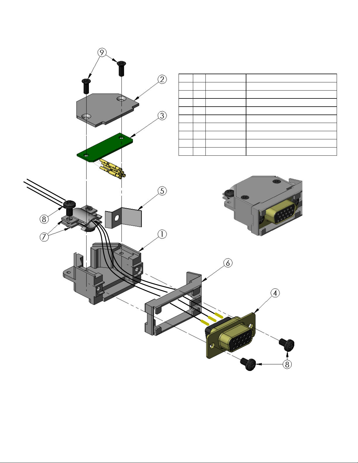
Item
Qty
Part Number
Description
1 1 9017218
Backs he ll , Si z e 9
2 1 9017274
Cover, Backshell
3 1 9017184-1
PCB Assy, Conf ig Module
4 1 9016479
Kit, DSub, 15pin HD
5 1 part of 9016479
DSub Backshell Spring Clip
6 1 part of 9016479
DSub Slide Lock, Size 9
7 2 part of 9016479
DSub Backshell Cable Clamp
8 4 90-406-00011
Screw 4-40X3/16 Pan Phil Blk Patch
9 2 90-208-10011
Screw 2-56X1/4 Flat Phil Blk Patch
Mid-Continent Instruments and Avionics, Wichita, KS
REV. B, October 31, 2012 17 Manual Number 9017782
FIGURE 2.3
CONFIGURATION MODULE ASSEMBLY
Page 18

Mid-Continent Instruments and Avionics, Wichita, KS
2.6 PITOT / STATIC CONNECTIONS
The connector kit supplied with the unit contains two (2) pneumatic quick disconnect fittings. These
fittings are specific to the connections on the rear of the unit and required for proper operation.
Aircraft tubing that connects to the unit must be ¼” OD with an approximate 0.17” ID. When
determining tubing length, be sure that it can extend through the cutout in the panel by approximately 8”
to allow the unit to be installed and removed from the front of the panel.
NOTE: It is helpful to identify/label each tube (pitot or static) so that it can be connected to
the correct por t on the back of the unit d uring installation.
2.7 MOUNTING
The MD302 is designed primarily to be front mounted in an aircraft instrument panel. Refer to Section
2.5in regards to Equipment Location. To install the unit in the instrument panel, follow the instructions
below and refer to Figures 2.4, 2.5 and 2.6.
1) Once a location is selected, cut the panel per the dimensions in Figure 2.5. Other notes to
consider for panel cutout: (the Nutplate can be used as a basic template for the panel cutout)
• For vertical installation, rotate the panel cutout profile 90°.
• Be sure to leave space clear on the front of the panel for the bezel of the unit, which will
extend significantly outside the main rectangular cutout.
• The dimension of the smaller side of the rectangle is critical for a good finished appearance.
If it is too large, the cutout will be visible outside the unit bezel. The relationship of the holes
to the cutout should be maintained closely to ensure proper installation.
• One countersink hole on either side of the rectangular cutout is required. Any of the three
hole locations is acceptable. More than one countersink hole one each side is opt ional.
Screws for these holes will retain the Nutplate and not support the weight of the unit.
• Verify that a flathead scr ew will sit flush or below the panel surface in the countersink holes.
If not, deepen the countersinks slightly.
• Remove burrs around the cutout and holes to allow the unit to mount flush with the panel.
2) Install the Nutplate on the backside of the instrument panel using at least one (1) flathead screw
on each side of the rectangular cutout.
• The Nutplate should mount flush to the backside of the instrument panel. The threaded nuts
in corners of the Nutplate should protrude to the rear.
3) Route the prepared cable harness and pitot/static fittings from behind the panel and through the
panel cutout. The length of the cable harness should allow the unit to be connected in front of
the panel.
4) VERIFY THAT AIRCRAFT POWER IS TURNED OFF.
5) Connect the cable harness with configuration module and pitot/static fittings to the rear of the
unit.
6) Insert the unit through the panel cutout and secure with four (4) hex cap screws provided.
• Electrical bonding between the aircraft and the unit chassis is NOT required.
2.8 INSTALLATION COMPLETION
Prior to operating the unit in the aircraft, verify the basic operation of the unit and condu ct a standard
leak check of the pitot/static system p er the aircraft maintenance manual or industry practice. When
initially powering the unit, an error may occur if a pre-configured unit is being mated to a Configuration
Module for the first time or if the unit has yet to be configured. Acknowledge this error and either
proceed to configuring the installation settings or cycle the power. The error should not occur for
subsequent startups.
REV. B, October 31, 2012 18 Manual Number 9017782
Page 19
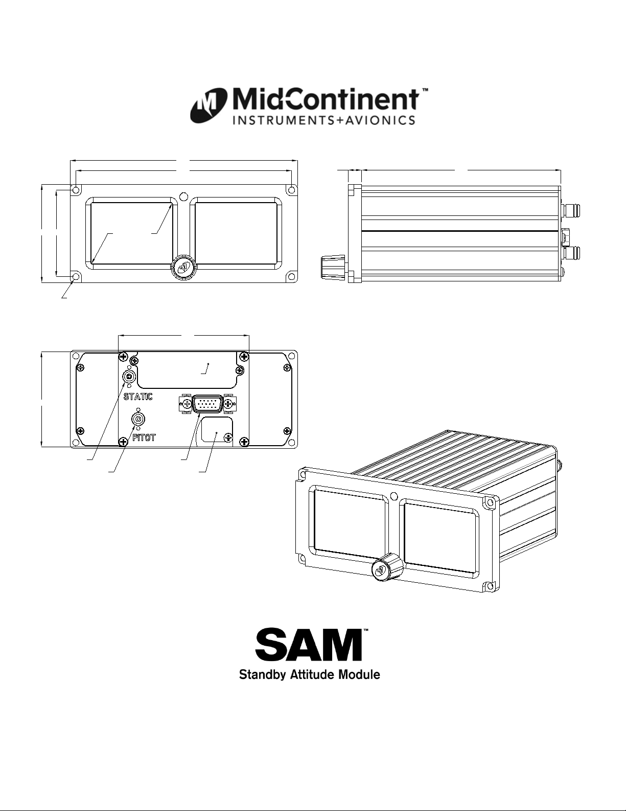
5.22
5.50
2.092.37
2.4" diagonal
active area
4X Ø0.150 thru
.33 4.82
3.16
2.30
static port
pitot port
USB access
15-pin D-sub
Battery access
FIGURE 2.4
Mid-Continent Instruments and Avionics, Wichita, KS
MD302 OUTLIN E DRAW IN G
REV. B, October 31, 2012 19 Manual Number 9017782
Page 20
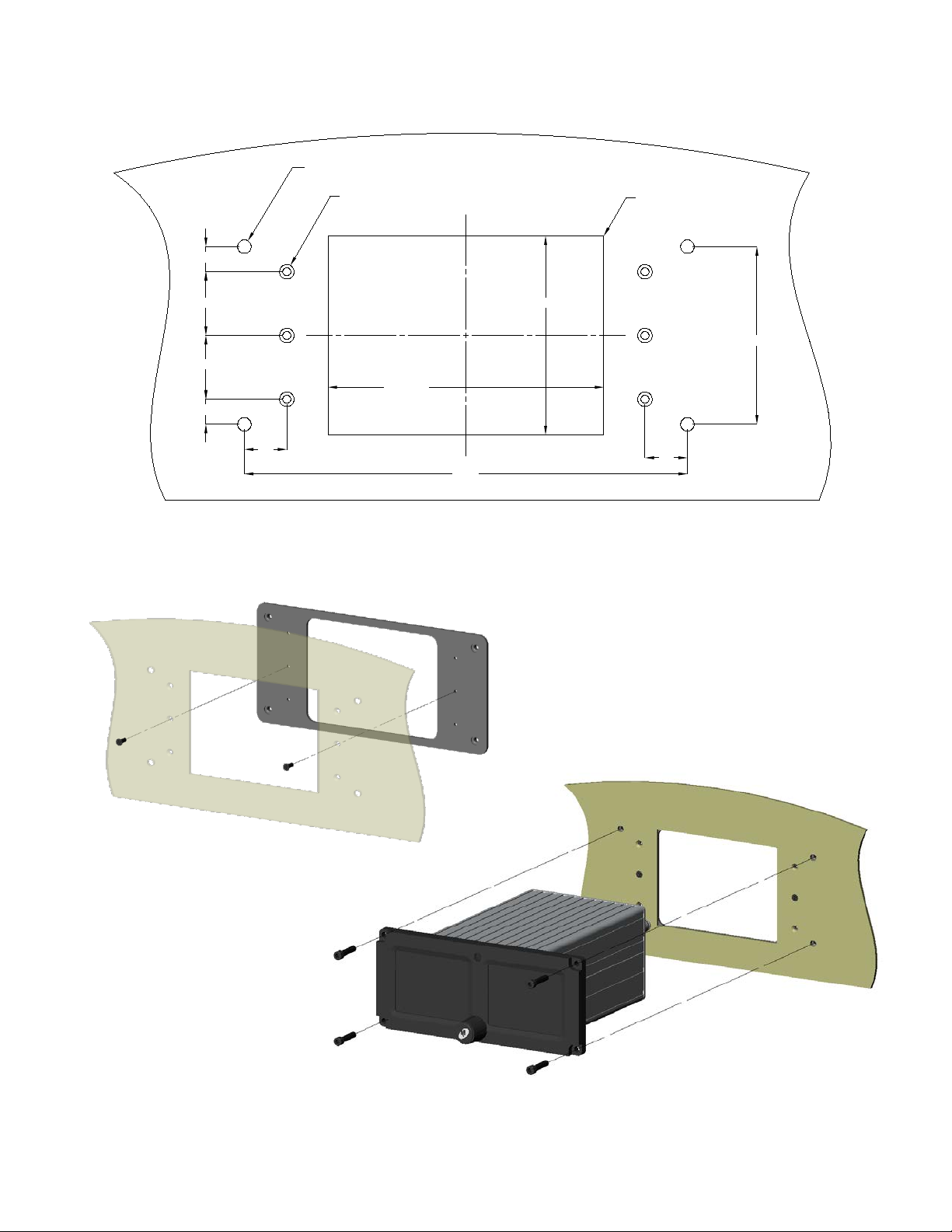
2.34±0.02
.50
.295
.750
.750
.295
3.25±0.05
2.090
5.220
.50
4X Ø.16±0.01 thru
w
Ø 0.175 X 82° countersink
only 1 of 3 required per side
4X R 0.10 max
FIGURE 2.6
FIGURE 2.5
STEP 1
STEP 2
Mid-Continent Instruments and Avionics, Wichita, KS
PANEL CUTOUT
REV. B, October 31, 2012 20 Manual Number 9017782
INSTALL ILLUSTRATION
Page 21
Mid-Continent Instruments and Avionics, Wichita, KS
SECTION 3 OPERATION
IMPORTANT: READ THIS ENTIRE SECTION PRIOR TO OPERATING THE UNIT
IN FLIGHT!
This section contains information on how to use and interpret the information presented to the pilot and
crew during normal and emergency operation of the MD302 Digital Flight Instrumen t.
3.1 USER INTERFACE
The MD302 Digital Flight Instrument is designed for simple, intuitive operation for ease of use
and quick interpretation of the inf orm ation displayed.
The central control knob can be located at the bottom-center, middle-left or middle-right of the
unit bezel depending on the installation orientation. This is the only user interface device on the
unit.
The knob has two functions: push and turn.
• The knob provides 16-detents per revolution and typically increments whatever element it
is controlling on the display one unit per detent.
• The push function is typically used to select the highlighted option in menus and/or to
enter and exit menus and control functions. The push function can also perform certain
operations with a push-and-hold action as described herein.
3.2 PRE-FLIGHT MODE
In Pre-flight Mode, power is applied to the unit and the introduction screen appears during
startup with the information shown in Figure 3.1.
During Pre-flight Mode, the startup screen shown in Figure 3.1 will be displayed while the unit
conducts an initial power-up built-in test (PBIT) of the system to validate operation al readiness.
This includes, among others, a battery c ap acity measurement, an internal ch e cksum to verify
software and memory, and a check that the internal settings and identification of the unit match
the Configuration Module installed in the aircraft cable harness.
The startup screen will be displayed for approximately 5 seconds and will transition to Flight
Mode when complete.
manufacturer’s logo
model name/num b er
software version
total operating time
REV. B, October 31, 2012 21 Manual Number 9017782
Page 22
Mid-Continent Instruments and Avionics, Wichita, KS
FIGURE 3.1 (cont)
PRE-FLIGHT MODE
3.3 FLIGHT MODE
In Fligh t Mode, the unit operates normally by display i ng the four major functions of attitude,
altitude, airspeed and slip information as shown in Figure 3.2. The Options Menu and brightness
adjustment are also accessible in Flight Mode.
FIGURE3.1
FIGURE3.2
REV. B, October 31, 2012 22 Manual Number 9017782
Page 23
Mid-Continent Instruments and Avionics, Wichita, KS
3.3.1 MAJOR FUNCTIONS
While in Flight Mode, the MD302 provides four major functions: attitude, altitude,
airspeed and slip indication.
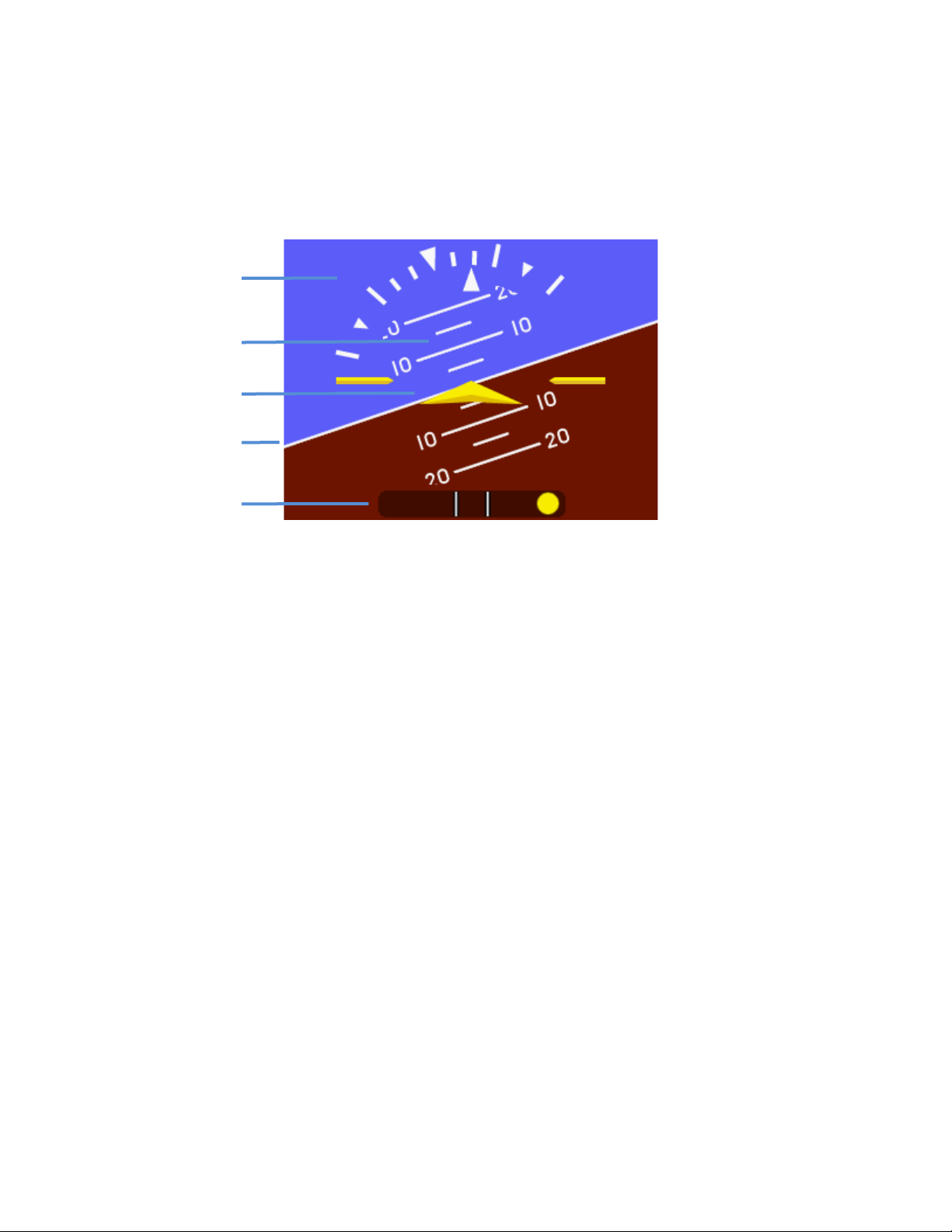
3.3.1.1 ATTITUDE OP E RATION
roll/bank scale
pitch scale
symbolic airplane
horizon line
slip indicator
The attitude indicator portion of the display will always appear on the left display when
the unit is oriented horizontally and on the top display when oriented vertically. An
example of the attitude display is shown in Figure 3.3.
The background of the display consists of the representative white horizon line
separating the ‘sky’ (blue) and ‘ground’ (brown).
The roll scale is depicted as an arc of graduations representing bank angles of 0
(triangle), 10, 20, 30, 45 (small triangle), and 60. The roll scale can be configured during
installation to be fixed to the sky/horizon or fixed to the t op of the disp la y. See Section 3
for how to c onfigure this option. The unit is operable and usable in a continuous and
unlimited roll range of 360°+.
The roll pointer is the triangle just below the roll scale and represents the aircraft in
relation to its bank angle. It is configured, by definit ion, to operate conversely to the roll
scale behavior. That is, a rotating roll scale produces a fixed roll pointer and a fixed roll
scale produces a rotating roll pointer.
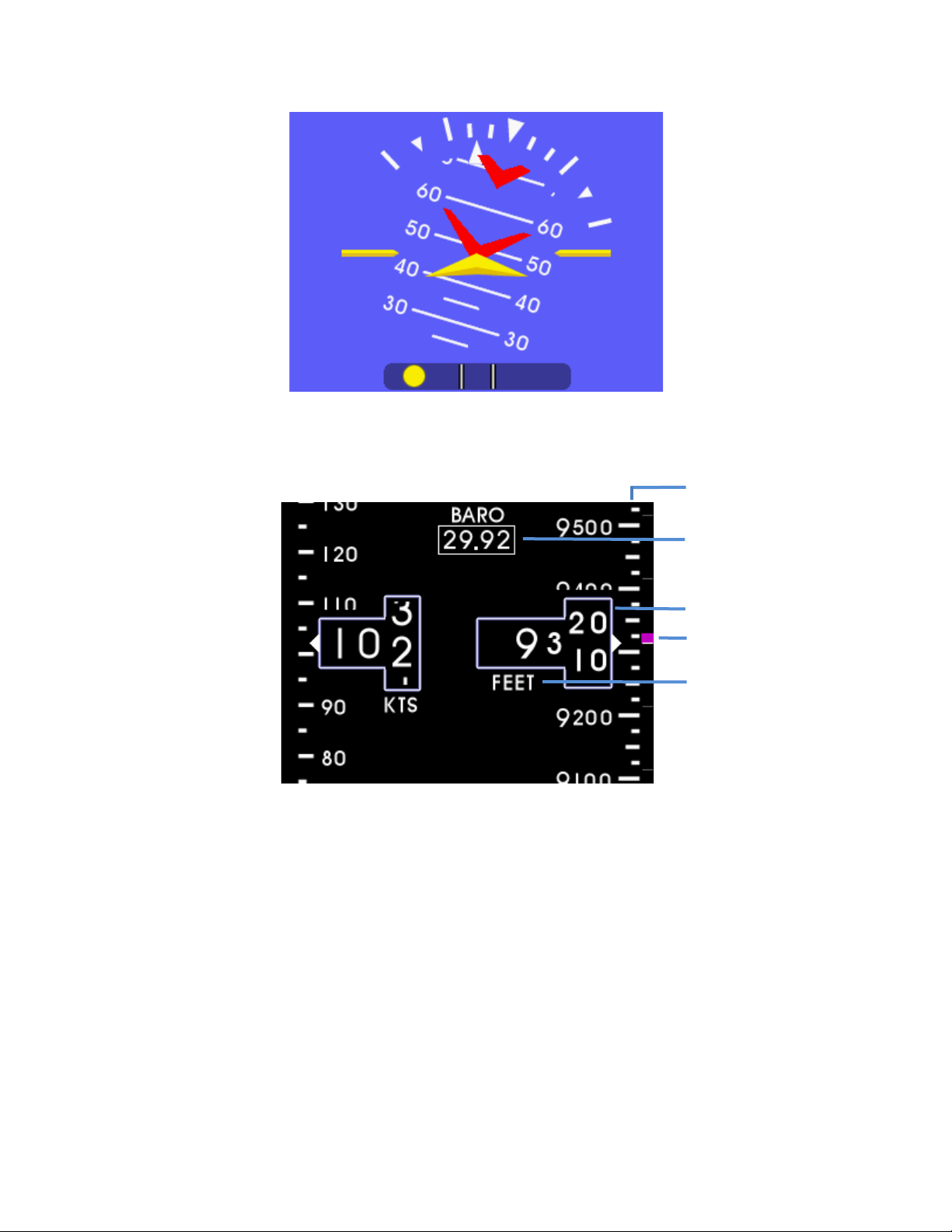
The pitch scale is depicted as a series of graduations representing pitch angles of every
5°, with every 10° graduation extended and numbered. The unit is operable and usable
in a continuous and unlimited pitch range of 360°+. A series of chevrons (^) will appear
overlaid on the pitch scale as seen in Figure 3.4. This is to indicate to the p il ot the
direction of the horizon for quick reference when in unusual pitch attitude.
The symbolic airplane wil l always remain in the center of t he display, with the
background elements moving behind it to represent the aircraft’s relative position. The
symbol that represents the airplane can be selected during Flight Mode using the Options
Menu (see Section 3.3.2).
FIGURE 3.3
REV. B, October 31, 2012 23 Manual Number 9017782
Page 24
barometer value
altitude window
altitude tape/scale
Mid-Continent Instruments and Avionics, Wichita, KS
FIGURE 3.4
3.3.1.2 ALTITUDE OPERATION
altitude trend bar
altitude units
FIGURE 3.5
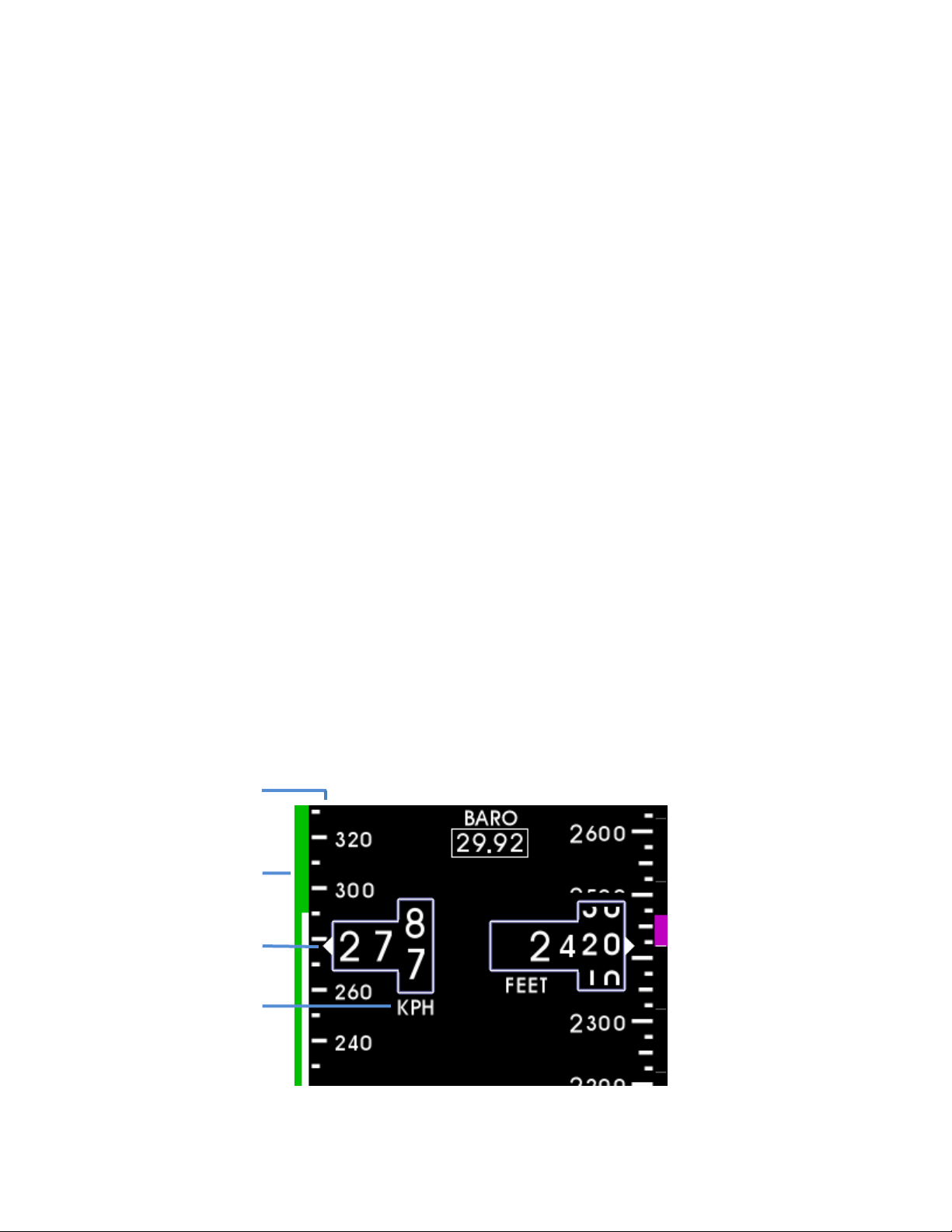
The altimeter or altitude portion of the display will always appear on the right side of the
right display when mounted horizontally and on the right side of the bottom display when
mounted vertically. An example of the altitude display is shown in Figure 3.5.
The altimeter consists of four parts: the altitude window, the altitude tap e , the
barometer window, and the opti on al altitude trend bar.
The altitude window displays the current, barometric adjusted altitude. The indicated
digits of the display are every ten (10) units and the window is expanded over this
portion of the number to display a minimum of (20) units. The units will ‘roll’ or scroll to
assist in quick reference as to the increasing or decreasing nature of the aircraft’s
altitude. The hundreds, thousands and ten-thousands digits appear to the left of the tens
digits with the thousands and ten-thousand digits slightly larger than the others. The
altitude pointer (triangle) to the right of the window points to the associated position on
REV. B, October 31, 2012 24 Manual Number 9017782
Page 25
Mid-Continent Instruments and Avionics, Wichita, KS
the altitude tape of the current altitude. Altitude units appear below the altitude window
and can be changed during Flight Mode using the Options Menu (see Section 3.3.2).
The altitude tape is a vertical scale along the right mar g in of the display. The current
altitude is always in the middle of the tape and indicated by the triangular pointer on the
right side of the altitude window. The tape has numeric indications every one-hundred
(100) units with minor graduations every fifty (50) units and sub-graduations every
twenty-five (25) units. In horizontal installations, the tape spans approximately 400 units
from top to bottom and in vertical installations, the tape spans approximately 500 units
from top to b ottom. The tape will ‘roll’ or scroll to assist in quick reference as to the
increasing or decreasing nature of the aircraft’s altitude.
The barometer window shows the currently set barometric pressure, is iden ti fie d b y the
abbreviation “BARO” and is located at the top center of the airspeed/altitude display.
Setting the current barometric pressure compensates the altitude for the appropriate
environmental conditions. The barometric setting can be adjusted with a simple turning
of the control knob while in Flight Mode. When adjusting the barometric pressure, the
window will increase in size and the digits will turn green. When finished setting the
pressure, the window will return to its original size and color. Barometric pressure units
can be selected during Flight Mode using the Options Menu (see Section 3.3.2).
The altitude trend bar is located along the right margin of the altitude display. This
feature is optional and can be turned on or off using the Options Menu (see Section
3.3.2). The trend bar is magenta in color and originates at the current altitude on the
altitude tape (always from the middle of the display, directly across from the altitude
pointer). The height of the trend bar, above or below the current altitude, indicates the
altitude of the aircraft on the altitude tape if the current vertical speed or ‘altitude trend’
is maintained over a period of six (6) seconds. For example, in Figure 3.5, the current
altitude is approximately 9,315 feet. The trend bar is at approximately 9,32 5 f e et,
indicating that the aircraft’s altitude w ill be 9,325 feet in 6 seconds if the current vertical
speed or climb is maintained constant. The length of the trend bar will increase with
increased dive or climb rates and approach zero or disappear entirely as the vertical
speed reaches zero in level flight.
3.3.1.3 AIRSPEED OPERATION
airspeed scale/tape
range markings
airspeed window
airspeed u nit s
FIGURE 3.6
REV. B, October 31, 2012 25 Manual Number 9017782
Page 26

Mid-Continent Instruments and Avionics, Wichita, KS
The airspeed indicator portion of the display will always appear on the left side of the
right display when mounted horizontally and on the left side of the bottom display when
mounted vertically. An example of the airspeed display is shown in Figure 3.6.
The airspee d indicator display consists of three parts: the airspeed window, the airspeed
tape, and the airspeed limitations or range markings.
The airspeed window displays the current indicated airspeed (IAS). The digits of the
display are enlarged for visibility and increment by one (1) unit. The un its will ‘roll’ or
scroll to assist in quick reference as to the increasing or decreasing nature of the
aircraft’s airspeed. The airspeed pointer (triangle) to the left of the window points to the
associated position on the airspeed tape of the current airspeed. Airspeed units appear
below the airspeed window and can be selected during installation in Configuration Mode
(see Section 4).
The airspeed tape is a vertical scale along the left margin of the display. The current
airspeed is always in the middle of the tap e and indicated by the triangular pointer on
the left side of the airspeed window. The tape has numeric indications every ten (10) or
twenty (20) units depending on the unit type selected. Minor graduations appear every
five (5) or ten (10) units, respectively. In horizontal installations, the tape spans
approximately 50 or 100 units from top to bottom and in vertical installations; the tape
spans approximately 80 or 160 un it s from top to bottom depending on unit type. The
tape will ‘roll’ or scroll to assist in quick reference as to the increasing or decreasing
nature of the aircraft’s airspeed.
The airspeed limitations, also known as “V-speeds”, are indicated with colored range
marking bands placed vertically along the left margin next to the airspeed tape. The
colors and values of each bar can be set during installation in Configuration Mode (see
Section 4). Colors should be selected based on industry-defined colors and V-speed limits
as defined by the aircraft’s specific Pilot’s Operating Handbook (POH). Range markings
can be represented by full-width bars, half-width bars and/or radial marks. A traditional
‘barber pole’ may also be displayed if the aircraft requires and provides, the appropriate
Vmo and/ or Mmo values.
3.3.1.4 SLIP OPERATION
The slip indicator portion of the di splay will always appear at the bottom of the attitude
display. An example of the slip indicator is shown in Figure 3.3.
The slip indicator is represented by a shaded translucent background with two white lines
around center and a yellow ball. The ends of the indicator represent ±7° of bank with no
centripetal acceleration. No further indication is provided for angles greater than 7°.
When the ball is maintained between the vertical lines during banking maneuvers, the
turn is considered “coordinated” without slip. Electronic damping of the ball movement is
provided to prevent overly sensitive response and comply with regulatory requirements.
The slip indicator background becomes semi-transparent if the roll scale or roll pointer
pass behind the indicator so that all elements are still visible.
REV. B, October 31, 2012 26 Manual Number 9017782
Page 27
Mid-Continent Instruments and Avionics, Wichita, KS
3.3.2 OPTION SETTINGS
While in Flight Mode, aOption Settings menu is available to the pilot or cockpit crew
members. The Option Settings offer multiple options that d o not affect the aircraft
specific configuration of the unit (these must be set in Configuration Mode by authorized
personnel during installation and/or maintenance). They are provided for convenience,
preference or potentially necessary in-flight adjustments.
The Option Settings menu can be accessed by pushing and holding the control knob for
approximately two (2) seconds. The brightness adjustment bar will appear briefly before
the menu is visible. The menu will appear in place of the attitude display and will revert
to the active attitude indicator if no activity occurs for ten (10) seconds.
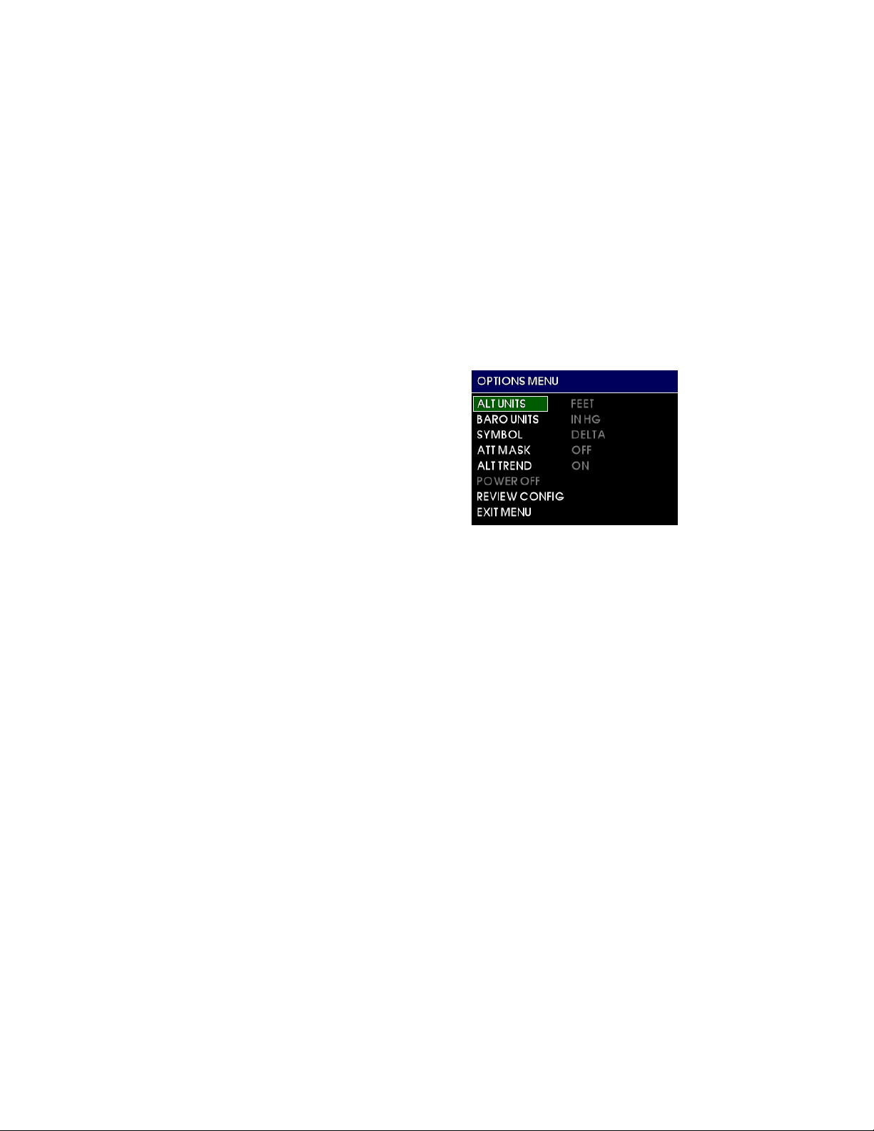
The Option Settings root menu contains the following options: (as shown in Figure 3.7)
• ALT UNITS
• BARO UN I TS
• SYMBOL
• ATT MASK
• ALT TRE N D
• POWER OFF
• REVIEW CONFIG
• EXIT MENU
3.3.2.1 MENU OPERATION
The menu parts are defined below:
Menu title – white text on a blue background at the top of each menu and sub-menu
Current item cursor – highlighted by a white box and green background
Selectable items – any selectable item on the menu is indicated in white text
Unavailable items – information only / unavailable options are indicated with gray text
Menu operation throughout the MD302 is simple and intuitive:
Turning the control knob will scroll the green cursor highlight over the available
options within the current menu. By default, the currently set value of each menu
option is displayed in gray directly to the right of each setting. Pressing the control
knob for any highlighted item will activate it and make its options available to the
right. Scroll to the desired option and press the control knob to select it. The green
highlight will return to the menu options on the left and the new value will be
displayed in gray to the right.
After confirming any setting by selecting it, that setting will become active and be
saved in memory, regardless of whether the EXIT MENU command is selected or it
times out and automatically reverts to the attitude display.
FIGURE 3.7
REV. B, October 31, 2012 27 Manual Number 9017782
Page 28
Mid-Continent Instruments and Avionics, Wichita, KS
3.3.2.2 ALT UNITS
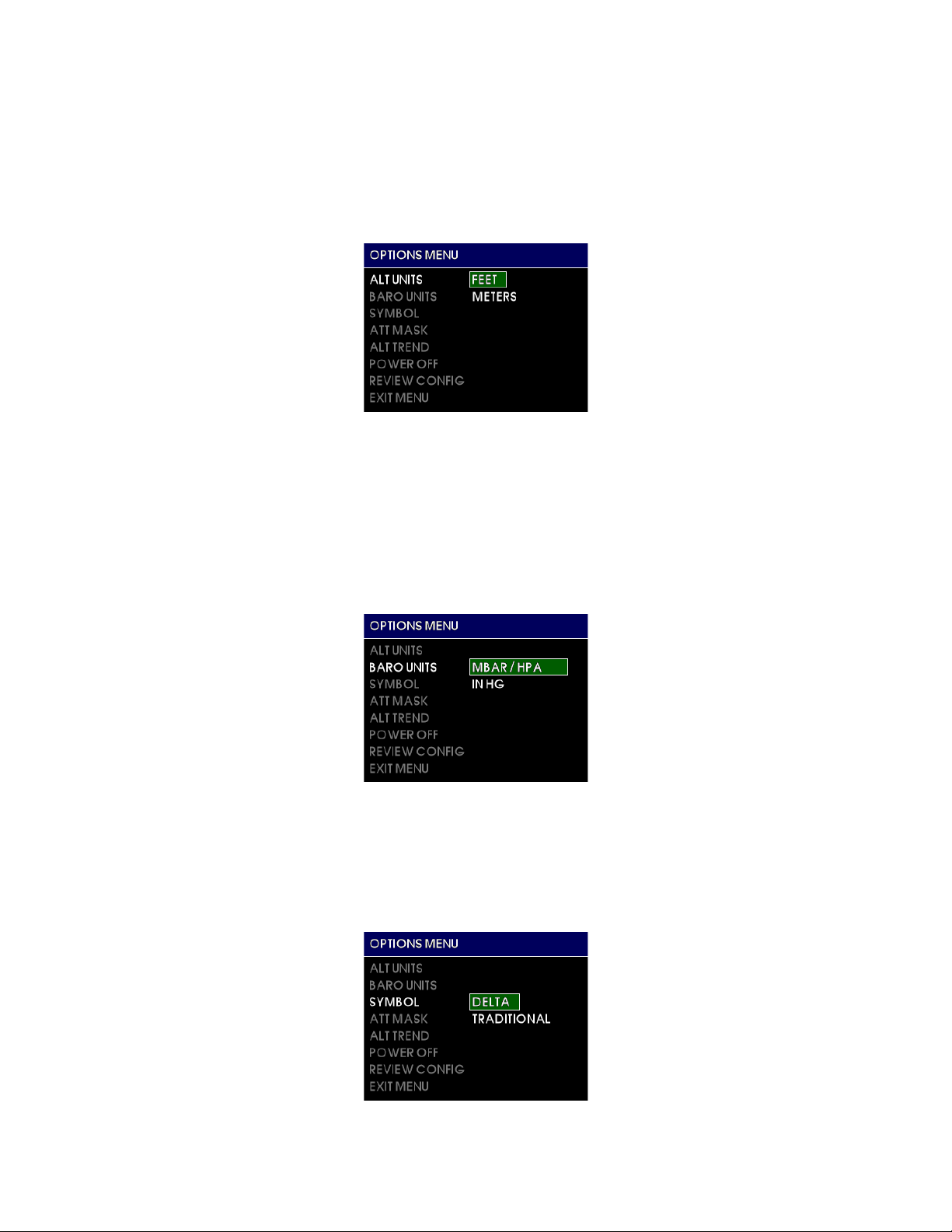
The ALT UNITS setting allows the user to select the altimeter or altitude units to
either FEET or METERS. This feature is provided during flight in the event that
the aircraft crosses airspace boundaries that require or report different altitude
units. See Figure 3.8.
FIGURE 3.8
3.3.2.3 BARO UNITS
The BARO UNITS setting allows the user to select the altimeter or altitude
barometric adjustment units to either inches of mercury (IN HG) or millibars
(MBAR)/hectopascals (HPA). This feature is provided during flight in the event
that the aircraft crosses airspace boundaries that require or report different
barometric units. See Figure 3.9.
FIGURE 3.9
3.3.2.4 SYMBOL
The SYMBOL setting allows the user to select the type of symbolic airplane on
the attitude display to either DELTA or TRADITIONAL. This feature is provided
for pilot preference and/or to match other instruments in panel. See Figure 3.10.
FIGURE 3.10
REV. B, October 31, 2012 28 Manual Number 9017782
Page 29
Mid-Continent Instruments and Avionics, Wichita, KS
FIGURE 3.11
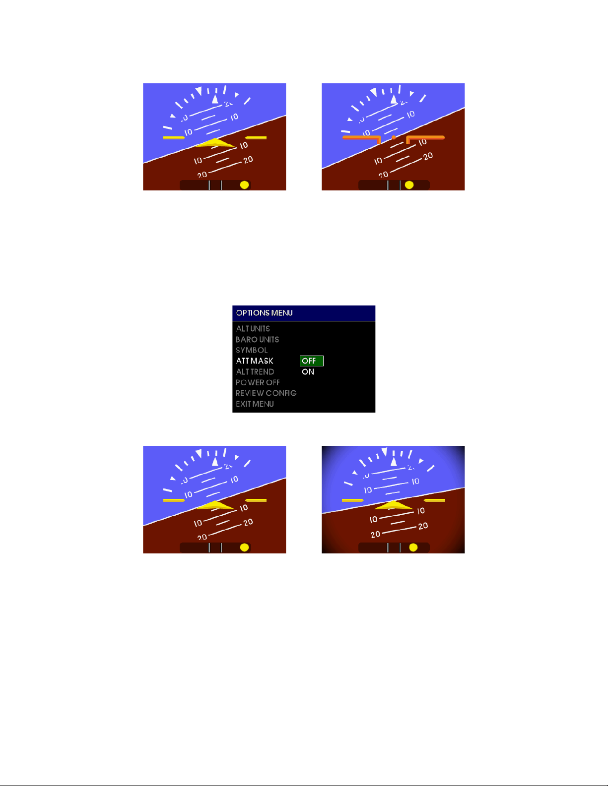
3.3.2.5 ATT MA SK
The ATT MASK setting allows the user to turn the attitude m ask ON or OFF. The
attitude mask provides gradien t d imm ing of the corners of the attitude display to
give the aesthetic look of a round instrument. See Figure 3.12 and 3.13.
FIGURE 3.12
FIGURE 3.13
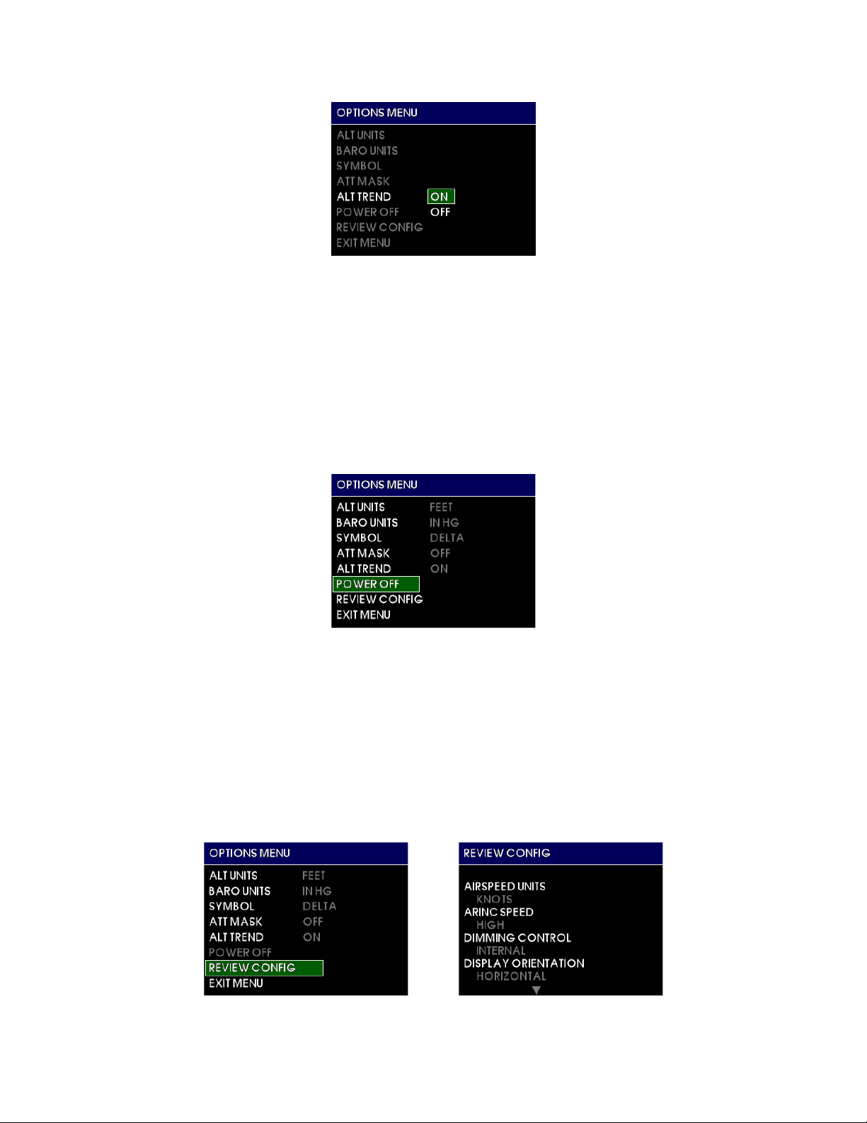
3.3.2.6 ALT TREND
The ALT TREND setting allows the user to turn the altitude trend bar ON or OFF.
The altitude trend bar provides a graphical representation of vertical speed near
the altitude tape (see Section 3.3.1.2). This feature is provided for pilot
preference and/or convenience. See Figure 3.14.
REV. B, October 31, 2012 29 Manual Number 9017782
Page 30
Mid-Continent Instruments and Avionics, Wichita, KS
FIGURE 3.14
3.3.2.7 POWER OFF
The POWER OFF action allows the user to immediately turn the unit off when it
is operating on its internal battery and there is no significant motion or airspeed
detected. There are no selectable options. This item is typically grayed out and
unavailable in flight mode. This feature is provided to turn the unit off when on
the ground and/or if inadvertently left on battery power. See Section 3.4 for
more information on Emergency Operation when operating on battery power.
See Figure 3.15.
FIGURE 3.15
3.3.2.8 REVIEW CONFIG
The REVIEW CONFIG action allows the user to view all the values which are
saved in unit memory and are set in Configuration Mode during installation or
maintenance. There are no selectable options and this feature provides a viewonly verification of information only. When selected, a new menu (REVIEW
CONFIG) will appear that allows the u ser to scroll through all the set values in
the configuration menu. Push the control knob to return to the Options Menu.
See Figure 3.16.
FIGURE 3.16
REV. B, October 31, 2012 30 Manual Number 9017782
Page 31
Mid-Continent Instruments and Avionics, Wichita, KS
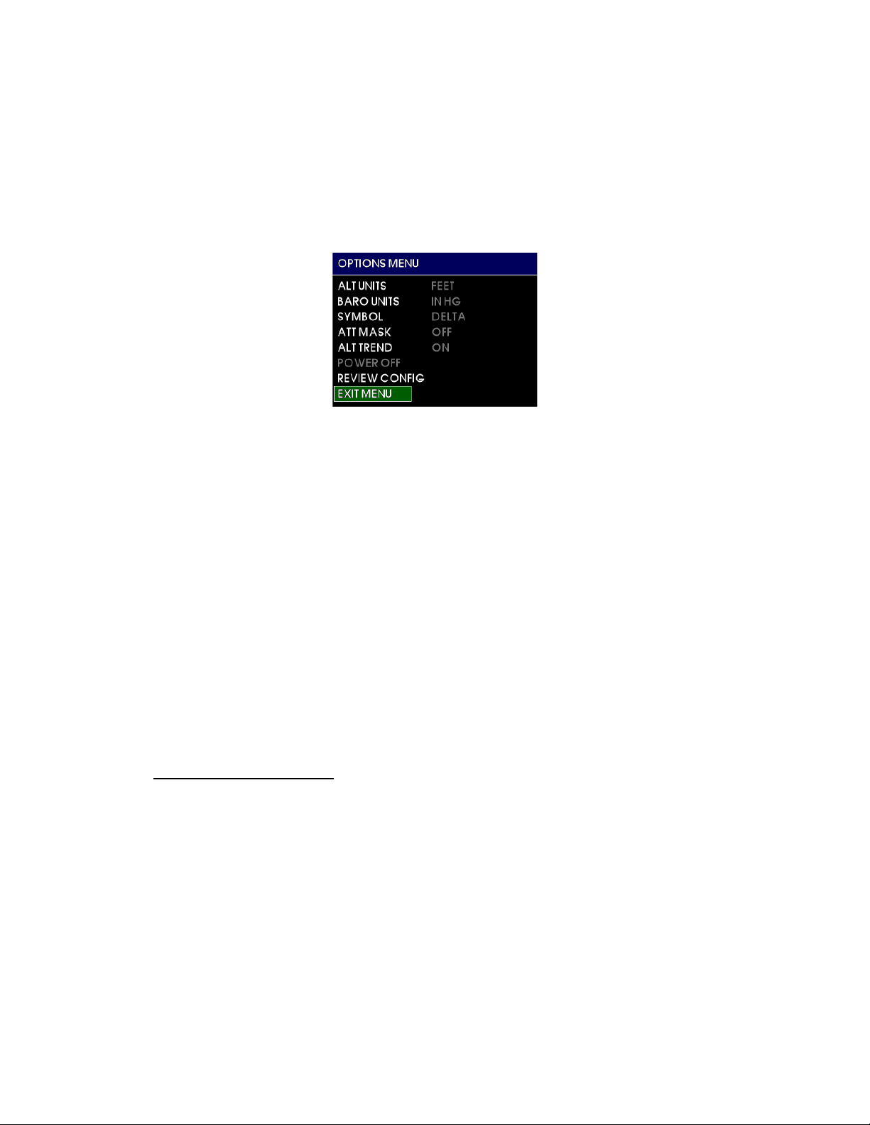
3.3.2.9 EXIT MENU
The EXIT MENU action allows the user to manually exit the Options Menu and
return to the active attitude indicator display. There are no selectable opt ions.
After confirming any setting by selecting it, that setting will become active and
be saved in memory, regardless of whether the EXIT MENU command is selected
or it times out (approximately 10 seconds of inactivity) and automatically reverts
to the attitude display. See Figure 3.17.
3.3.3 BRIGHTNESS AD J USTMENT
The MD302 unit can be configured to adjust its brightness based on the aircraft’s manual
lighting bus control or automatically based on the ambient lighting conditions using the
photocell sensor on the unit. For either option (selected in the Configuration Mode, see
Section 4) the pilot or crew member can override the current brightness and manually
increase or decrease it. To do this, briefly press the control knob. The brightness bar will
appear overlaid on the attitude display and turning the control knob will increase or
decrease the current setting.
While the unit remains powered, the manual adjustment will remain saved and any
change in the lighting bus or photocell sensor will increase or decrease the brightness
from the newly set manual adjustment.
When the unit is powered off, the manual adjustment will be reset and default to the
lighting response curve programmed into memory per the settings in the Configuration
Mode setup.
3.4 EMERGENCY OPE RATION
3.4.1 IN FLIGHT
The MD302 is designed to operate reliably and provide the critical situational awareness needed
even if the aircraft power systems fail. When this occurs, the unit provides emergency operation
by continuing to perform seamlessly and uninterrupted in Flight Mode.
The MD302 contains an internal and field-replaceable True Blue Power
ion battery which recharges during normal flight and provides a minimum of one (1) hour of
operation and as much as 2.5 hours when new.
When primary aircraft power to the unit is lost in flight, the unit will immediately begin operating
on internal battery power. This is indicated by a green battery icon displayed in the top right of
the attitude display. See Figure 3.18.
FIGURE 3.17
®
Nanophosphate®Lithium-
REV. B, October 31, 2012 31 Manual Number 9017782
Page 32
battery icon
Mid-Continent Instruments and Avionics, Wichita, KS
FIGURE 3.18
EMERGENCY O PERATION
When operating on battery power and it becomes low, the battery icon will change to the low
battery icon. This is identified by a black battery icon with a red X on it. This indicates that there
is less than 20% of battery capacity left and may represent as little as 10 minutes of backup
power available. See Figure 3.18.
3.4.2 ON THE GROUND
When primary aircraft power to the unit is lost, the unit will immediately begin operating on
battery power. If this occurs as a result of normal landing and shut-down procedures, the unit
will recognize that there is no aircraft motion and no airspeed and determine that the aircraf t is
on the ground. Under these conditions, the unit will then display a warning message as shown in
Figure 3.19. The unit will begin counting down for 60 seconds and then turn off automatically.
If continued operation is desired, press the control knob to select OK. If you want to turn the unit
off after acknowledging the ‘remain on’ option, enter the Options Menu and select the POWER
OFF action. See Section 3.3.2.1.
FIGURE 3.19
REV. B, October 31, 2012 32 Manual Number 9017782
Page 33
Mid-Continent Instruments and Avionics, Wichita, KS
SECTION 4 CONFIGURATION SETUP
IMPORTANT: THE UNIT IS NOT APPROVED FOR FLIGHT UNTIL IT HAS BEEN
CONFIGURED FULLY USING THE INSTRUCTIONS IN THIS SECTION!
This section contains information on how to configure the various requirements and options the
MD302 Digital Flight Instrument offers in regards to the specific aircraft that it is installed in, including
critical flight parameters that con tr ibu tes to the safe and certified operation of the unit and the
aircraft.
Several safeguards are in place to prevent a user from ever accessing the configuration mode while in
flight. Only authorized installers and trained personnel should access the configuration mode during
initial installation or during maintenance, adjustments and updates.
This section discusses the Configuration Mode/Menu completely and is organized into the follo wing
categories:
• Configuration Mode/Menugeneral usage and purpose
• Display Configuration
• Dimming Configuration
• Aircraft Configuration
• Configuration Mode Actions
4.1 CONFIGURATION MODE/MENU
In Configuration Mode, all of the parameters specific to th e aircr aft and particular installation are
set and saved into permanent memory . These configuration settings are also saved to the
external Configuration Module that is part of the aircraft’s cable harness. This allows for the unit
to be removed and/or replaced for service or other aircraft maintenance and still retain the
configuration settings associated with the aircraft.
To enter the Configuration Mode, press and hold the control knob prior to applying power to the
unit. After approximately six (6) seconds, the following message will appear:
“CONTINUE HOLDING TO ENTER INSTALLER MODE”.
After a few more seconds, the introduction screen will appear and the knob can be released. You
will now see the CONFIGURE MENU as shown in Figure 4.1.
FIGURE 4.1
REV. B, October 31, 2012 33 Manual Number 9017782
Page 34
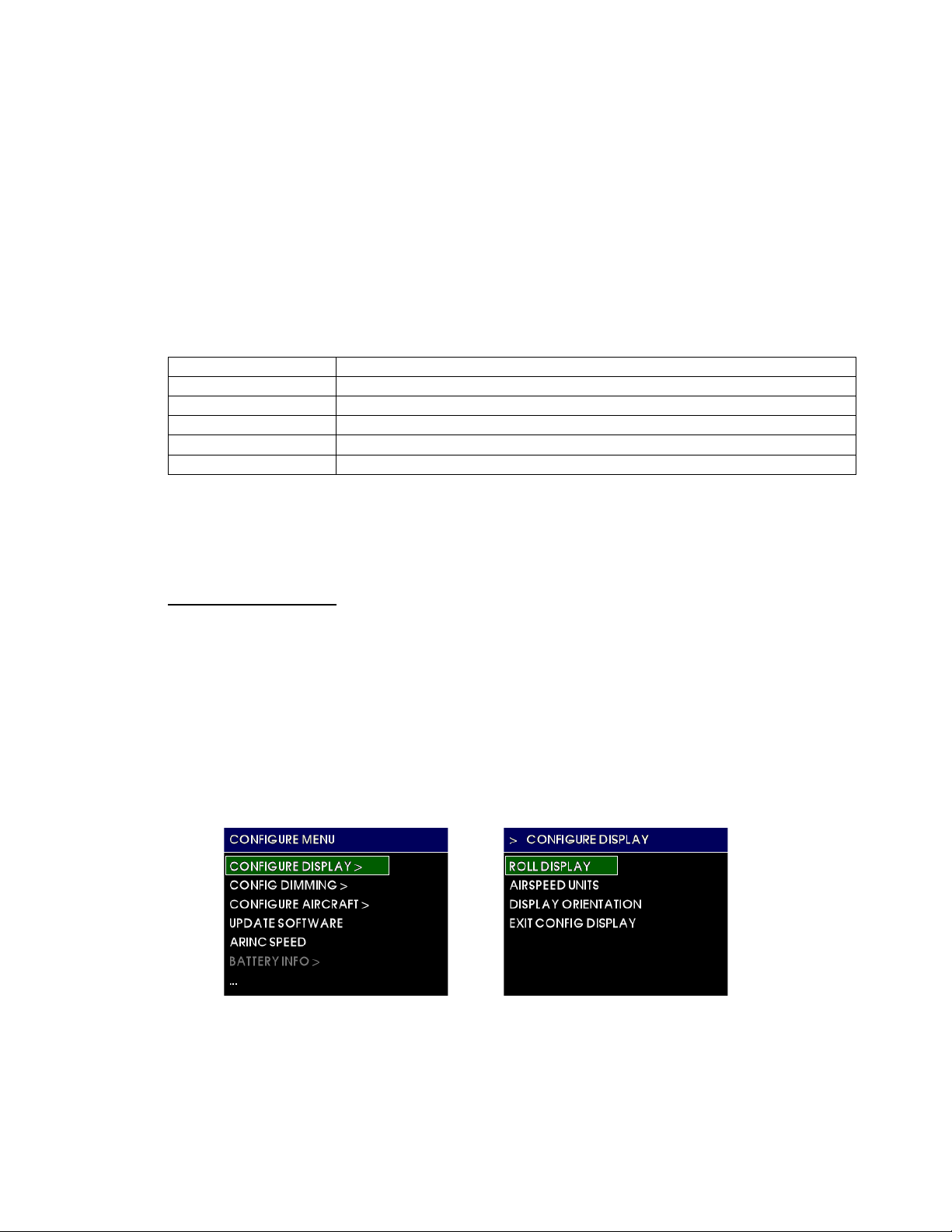
Menu title
white text on a blue background at the top of each menu and sub-menu
Current item cursor
highlighted by a white box and green background
Selectable items
any selectable item on the menu is indicated in white text
Unavailable items
information only / unavailable options are indicated with gray text
>
indicates an item has another menu page associated with it
…
indicates there are more options available past the bottom of the screen
Mid-Continent Instruments and Avionics, Wichita, KS
The CONFIGURE MENU root directory contains the following sub-menus and actions:
• CONFIGURE DISPLAY
• CONFIG DIMMING
• CONFIGURE AIRCRAFT
• UPDATE SOFTWARE
• ARINC SPEED
• BATTERY INFO
• POWER OFF
• ACCEPT CHANGES
• CANCEL CHANGES
The parts of the menu structure are defined below:
Menu operation throughout the MD302 is simple and intuitive. See Section 3.3.2.1 for details.
NOTE: In Configuration Mode, unlike in the Options Menu, any changes made to any settings will not
be saved unless you select ACCEPT CHANGES prior to exiting the Configuration Mode/Menu.
4.2 CONFIGURE DISPLAY
When the CONFIGURE DISPLAY menu option is selected, it opens the sub-menu shown below in
Figure 4.2. Note the sub-menu title at the top of the screen and indication (>) that there i s a par ent
menu associated with it. The EXIT CONFIG DISPLAY will return the user back to the CONFIGURE
MENU.
Within the CONFIGURE DISPLAY sub-menu are the following options:
• ROLL DISPLAY
• AIRSPEED UNITS
• DISPLAY ORIENTATION
• EXIT CONFIG DISPLAY
FIGURE 4.2
REV. B, October 31, 2012 34 Manual Number 9017782
Page 35
Mid-Continent Instruments and Avionics, Wichita, KS
4.2.1 ROLL DISPLAY
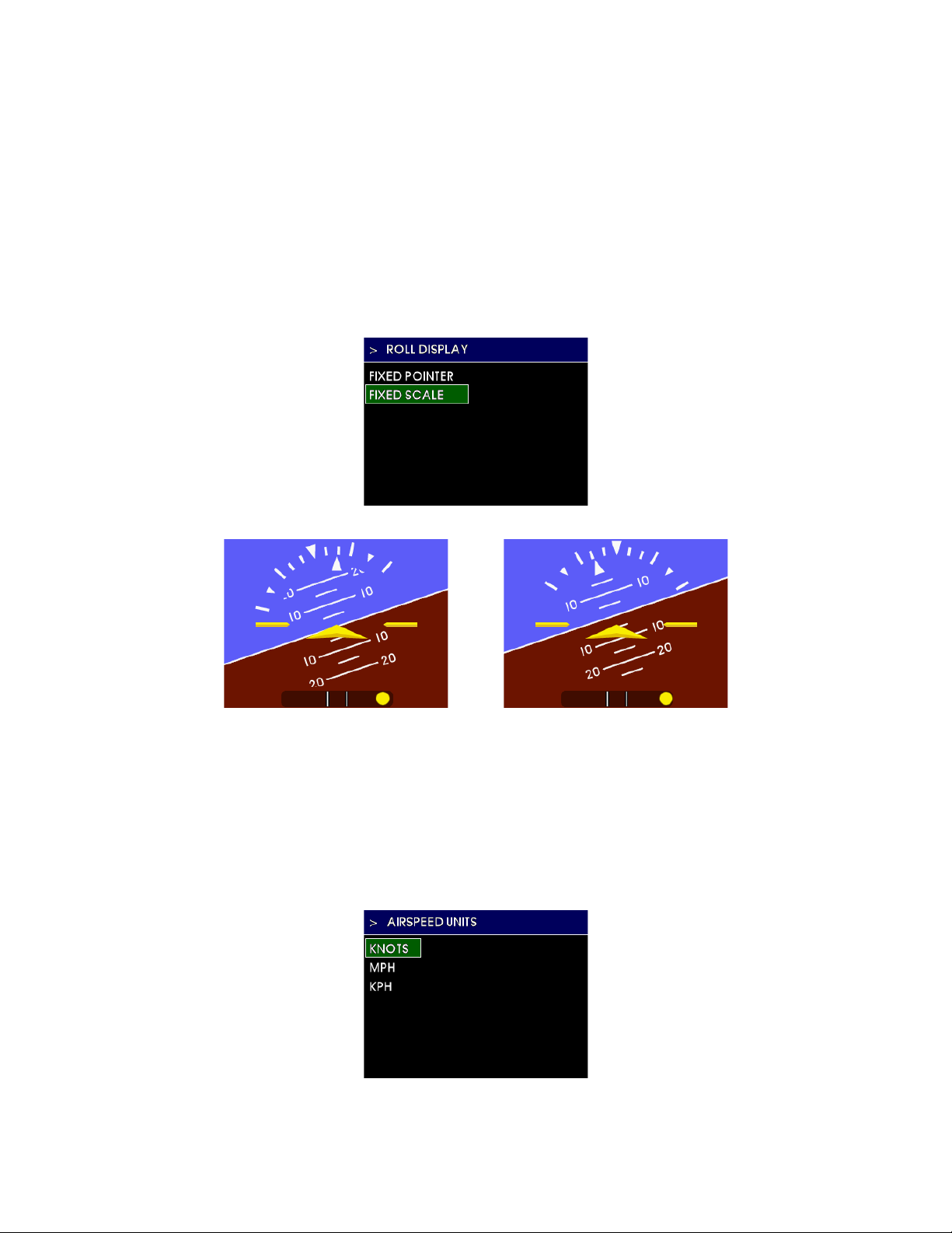
The ROLL DISPLAY setting allows the installer to select either the FIXED POINTER or
FIXED SCALE option. With the FIXED POINTER, the roll scale containing the radial grads
and triangles on the attitude display rotate with the horizon and the lower triangle
pointer always points to the top of the d isplay and represents the aircraft’s pos iti on in
relation to the scale. The FIXED SCALE (also known as ‘sky pointer’) option sets the role
scale stationary and allows the triangle pointer to rotate with the horizon . This feature
should be selected to match other attitude instrument representations in the panel for
consistency and reduced fatigue/work load on the pilot when switching field-of-view
between instruments. See Figure 4.3 and 4.4.
FIGURE 4.3
FIXED POIN TER FIXED SCALE
FIGURE 4.4
4.2.2 AIRSPEED UNITS
The AIRSPEED UNITS setting allows the installer to select the airspeed units to KNO TS,
MPH (miles per hour) or KPH (kilometers per hour). This feature should be selected to
match the other airspeed instrument representations in the panel for consistency and
reduced fatigue/work load on the pilot when switching field-of-view between
instruments. See Figure 4.5.
FIGURE 4.5
REV. B, October 31, 2012 35 Manual Number 9017782
Page 36
Mid-Continent Instruments and Avionics, Wichita, KS
4.2.1 DISPLAY ORIENTATION
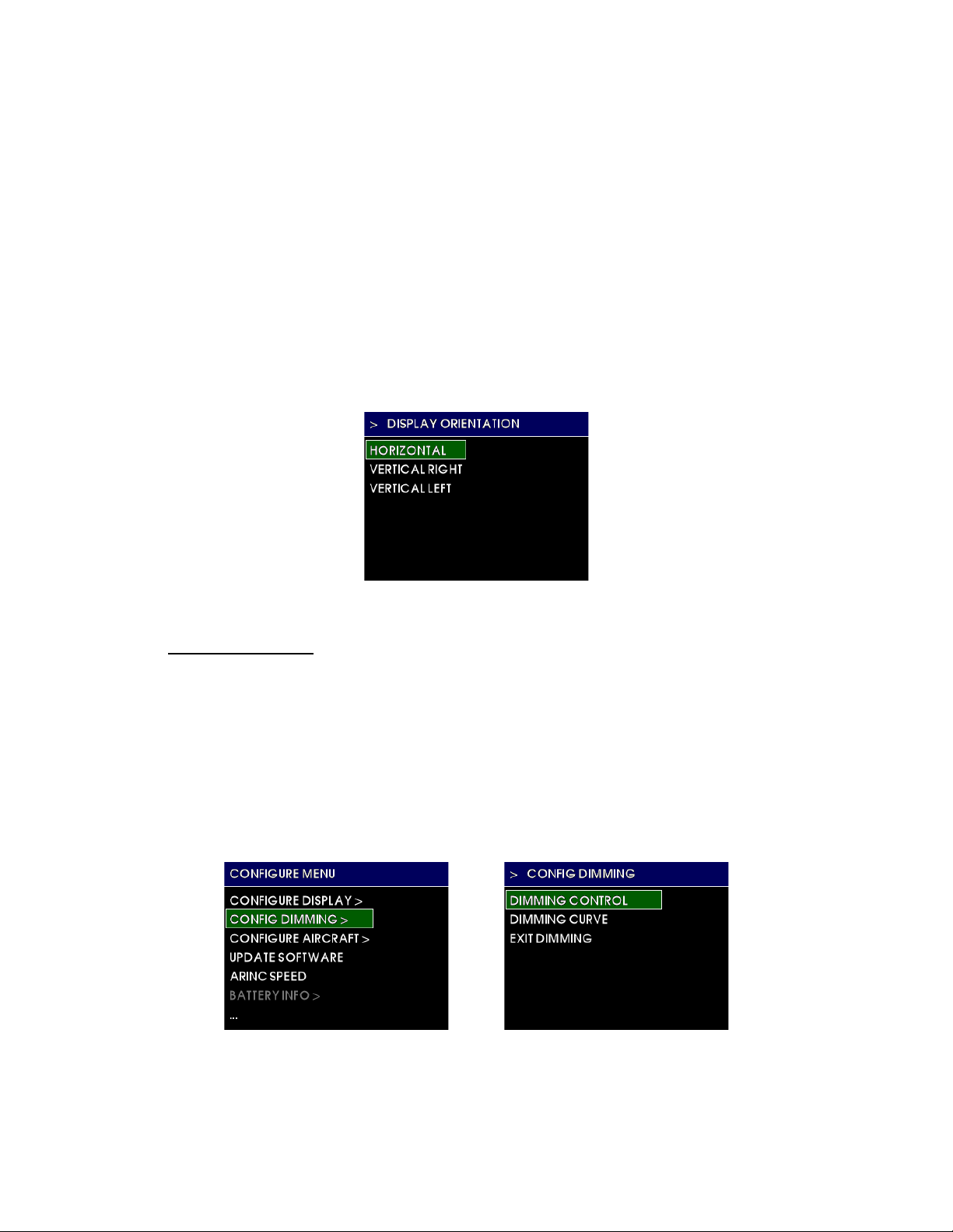
The DISPLAY ORIENTATION setting allows the installer to select the orientation that the
unit w ill be installed in the panel. It can be installed HORIZONTAL , VERTICAL RIGHT, or
VERTICAL LEFT. In the HORIZONTAL orientation, the unit must be installed with the
control knob at the bottom of the un it. In the VERTICAL RIGHT orientation, the control
knob is located on the right side of the unit. In the VERTICAL LEFT orientation, the
control knob is located on the left side of the unit. See Section 2.3 Equipment Location
when choosing the where and how to orient the unit in the aircraft instrument panel.
This feature is provided for maximum installation flexibility but should be chosen carefully
to fully comply with regulatory requirements which minimizes visual scan and is easily
accessible. NOTE: in the vertical orientation, the location of the knob should be selected
so that the pilot does not obstruc t the display when operating the control knob. See
Figure 4.6 and Figure 2.1.
4.3 CONFIG DIMMING
The CONFIG DIMMINGmenu option opens the sub-menu shown below in Figure 4.7. Note the submenu title at the top of the screen and indication (>) that there is a parent menu associated with it.
The EXIT DIMMING will retur n the user back to the CONFIGURE MEN U.
Within the CONFIGURE DISPLAY sub-menu are the following options:
• DIMMING CONTROL
• DIMMING CURVE
• EXIT DIMMING
FIGURE 4.6
FIGURE 4.7
REV. B, October 31, 2012 36 Manual Number 9017782
Page 37
Mid-Continent Instruments and Avionics, Wichita, KS
4.3.1 DIMMING CONTROL
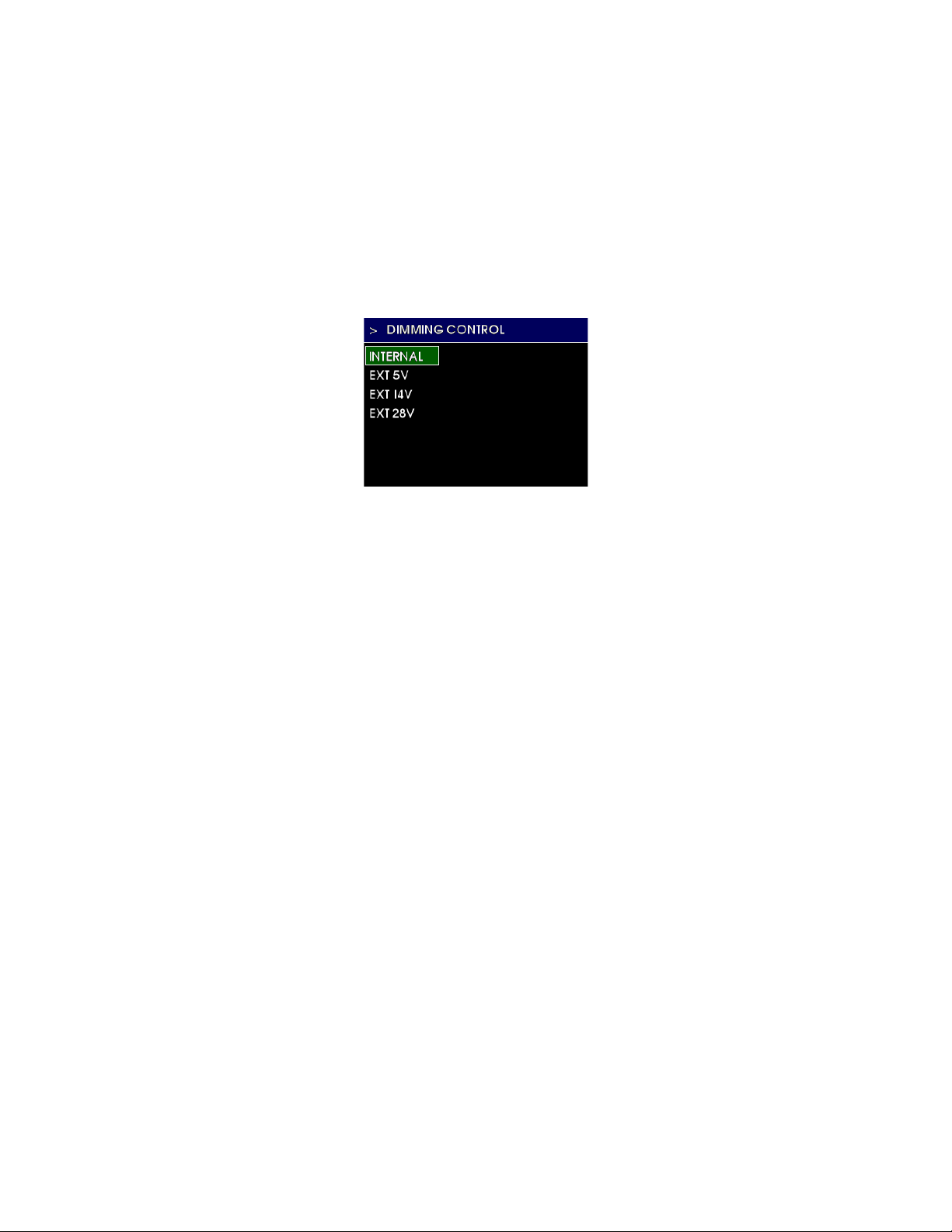
The DIMMING CONTROL setting allows the installer to select the source of dimming
control. It can be an external source , typically the aircraft’s adjustable lighting b us, or it
can use the INTERNAL photocell built into the unit which senses the ambient light
conditions and adjusts the display brightness/dimming automatically. If an external
source is to be used, the EXT 5V, EXT 14V, and EXT 28V options represent the input
voltage range the unit will accept ( 0-5VDC, 0-14VDC, and 0-28VDC, respectively).
This feature is provided for maximum installation flexibility and control for the pilot.
See Figure 4.8.
FIGURE 4.8
4.3.2 DIMMING CURVE
The DIMMING CURVE feature allows the installer to customize the response to the
DIMMING CONTROL input, whether internal or external, over its range of operation.
Therefore, for various points throughout the input range, the brightness can be adjusted
up or down to produce a unique dimming scheme that most closely matches the other
instruments in the panel and the pilot’s preferences. This feature is provided for
maximum installation flexibility and control for the pilot.
NOTE: When new, the display is daylight-visible at approximately 75% brightness. It may
not be necessary to set the dimming curve to 100%. Setting the high-brightness side of
the dimming curve to less than 100% will extend the life of the LED backlight and
provide margin for the pilot to increase brightness as desired.
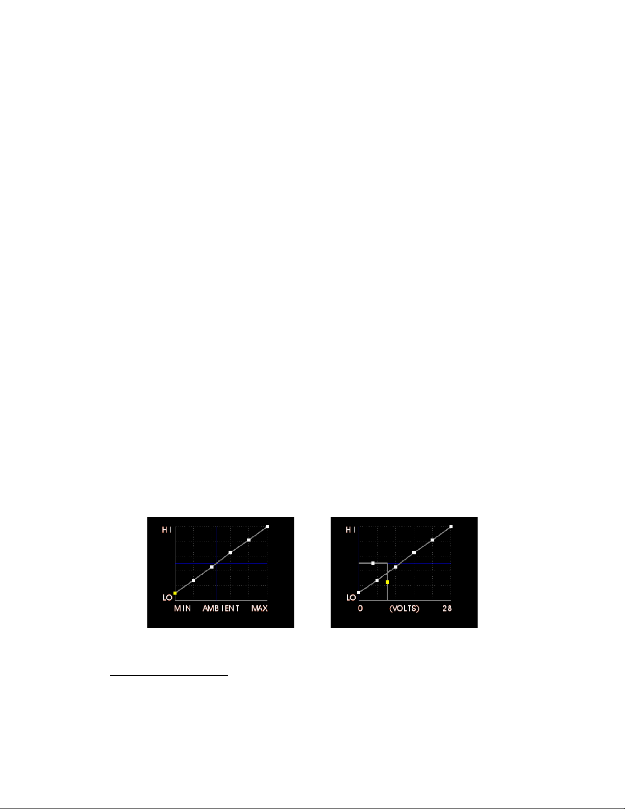
When setting the dimming curve with the dimming control set to INTERNAL, the X-axis
of the dimming graph will read AMBIENT and will range from MIN to MAX. This
represents the brightness of the light the unit’s photocell can see and shows the current
ambient light level with the vertical blue line. The Y-axis represents brightness of the
display. It will track the dimming cur ve with the horizontal blue line as the input light
increases or decreases. The best method for setting the dimming curve is to simulate the
range of lighting conditions. This is best done after installation, in the actu al aircraft
instrument panel, but can be simulated in various environments. See Figure 4.9.
1) Change the light of the cockpit or general area around the unit until the vertical
blue line matches (or nearly matches) the yellow highlighted point on the graph.
2) Adjust the control knob to increase or decrease the brightness of the display
to the desired level at that lighting condition (the point will move up or
down, respectively).
3) When satisfied, press the control knob.
4) The next point will be highlighted.
5) Repeat Steps 1-4 for each point on the graph.
REV. B, October 31, 2012 37 Manual Number 9017782
Page 38
Mid-Continent Instruments and Avionics, Wichita, KS
When setting the dimming curve with the dimming control set to external input (EXT
5V/EXT 14V/ EXT 28V), the X-axis of the dimming graph will read VOLTAGE and will
range from 0 to (5, 14 or 28). This represents the voltage input of the lighting bus and
shows the current input with the vertical blue line. The Y-axis represents brightness of
the display. It will track the dimming curve with the horizontal blue line as the input
voltage increases or decreases. With a lighting bus input, the dimming curve adds a ‘lowlevel output’ feature. This allows the unit to be set to a high-brightn ess level to maintain
daylight visibility when the lighting bus is turned down very low or off, as it may be
during daylight hours. The best method for setting the dimming curve is to simulate the
range of lighting inputs or conditions to match other instruments. This is best done after
installation, in the actual aircraft instrum ent panel, but can be simulated in various
environments. See Figure 4.10.
1) Change the lighting bus input until the vertical blue line matches (or nearly
matches) the yellow highlighted point on the graph.
2) Adjust the control knob to increase or decrease the brightness of the display
to the desired level at that lighting bus position (the point will move up or
down, respectively).
3) When satisfied, press the control knob.
4) The next point will be highlighted.
5) Repeat Steps 1-4 for each point on the sloped line of the graph.
6) The next highlighted point will be on the vertical zero line. As the lighting
bus is turned down or off, there may be a point where it should default to a
set level (typ ically for daylight visibility). Adjust t his dot horizontally with the
control knob to set the low-input level of the lighting bus where the default
brightness takes effect. You can verify where this occurs by adjusting the
lighting bus input. Press the control knob to accept the position chosen. If
this point is not set, the disp l ay will follow the dimmi ng curve previously
programmed and will be respond to the position of the first point when the
lighting bus is turned off.
7) The next highlighted point will set the default low-input brightness. With the
lighting bus input to the left of the previous set point, adjust the brightness
up or down to the desired level. Press the control knob to accept the position
chosen.
FIGURE 4.9 FIGURE 4.10
4.4 CONFI GURE AIRCRAFT
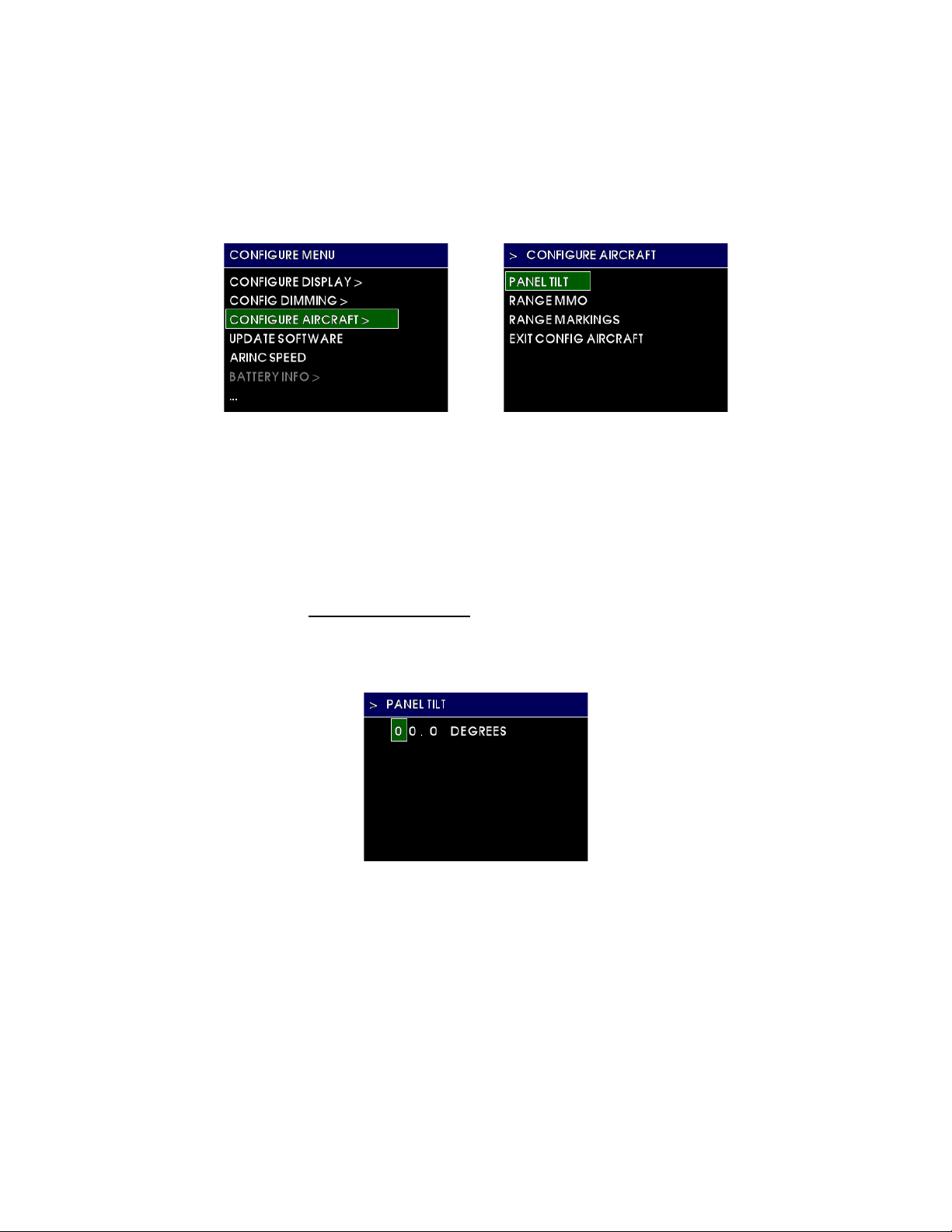
The CONFIGURE AIRCRAFT menu option opens the sub-menu shown below in Figure 4.11. Note the
sub-menu title at the top of the screen and ind ication (>) that there is a parent menu associated with
it. The CONFIGURE AIRCRAFT will return the user back to the CONFIGURE MENU.
REV. B, October 31, 2012 38 Manual Number 9017782
Page 39
Mid-Continent Instruments and Avionics, Wichita, KS
Within the CONFIGURE AIRCRAFT sub-menu are the following options:
• PANEL TILT
• RANGE MMO
• RANGE MARKINGS
• EXIT CONFIG AIRCRAFT
FIGURE 4.11
4.4.1 PANEL TILT
The PANEL TILT setting allows the installer to input the angle of the instrument panel so
that the attitude indicator will show zero pitch when in level flight. Use the control knob
to change the value of each panel tilt digit and press the control knob to acknowledge
each selection and advance to the next one. See Figure 4.12.
NOTE: It is extremely impor tant to measure and input the panel tilt angle accurately
for proper operation of the unit. Panel tilt should be measured using a digital level or
equivalent within ±0.5° when in level flight or as simulated on the ground. See the unit
specifications for the total range of acceptable panel tilt angles.
FIGURE 4.12
4.4.2 RANGE M MO
The RANGE MMO setting allows the installer to input the maximum operating Mach
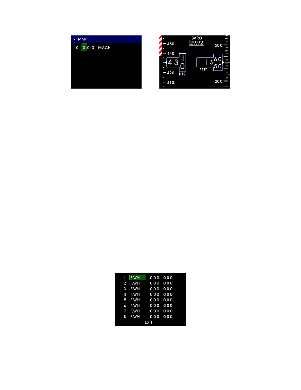
number specific to the aircraft. This is represented by a moving “barber pole” (red and
white striped) color bar to the left of the airspeed tape that adjusts with varying airspeed
and altitude. NOTE: THIS ONLY APPLIES TO AIRCRAFT WHICH PUBLISH A MAXIMUM
OPERATING MACH NUMBER. The value should be zero for those aircraft which do not
publish a maximum operating Mach number (M
). Use the control knob to change the
MO
value of each digit and press the control knob to acknowledge each selection and
advance to the next one. See Figure 4.13.
REV. B, October 31, 2012 39 Manual Number 9017782
Page 40
Mid-Continent Instruments and Avionics, Wichita, KS
FIGURE 4.13
MMO EN TRY PAGE AND SAMPLE SCREEN
4.4.3 RANGE MARKINGS
The RANGE MARKINGS setting allows the installer to input airspeed limits (or “V-speeds”)
specific to the aircraft. Aircraft airspeed limits can typically be found in the Pilot’s
Operating Handbook (POH). The range markings for airspeed limits appear as a series of
colored bars to the left of the airspeed tape.
To program range markings: (See Figure 4.14)
1) Use the control knob t o se lect the width of the color bar (H = Half, F = Full)
and the desired color.
2) Press the control knob to accept the selection and move to the range values.
3) Turn the control knob to select eac h digit and press to move to the next
digit.
a. The first three digits are the start or lower limit of the color bar
range and the second three digits are the upper limit.
b. A ‘radial’ or tick-mark can b e made at any value by selecting the Full
(F) width and desired color, then setting the lower limit and upper
limit to the same desired value.
c. The values automatically represent the units (knots, mph, kph)
selected in the CONFIGURE DISPLAY > AIRSPEED UNITS menu .
4) Continue in sequence until reaching the EXIT prompt and press the control
knob to exit the menu.
a. Leaving or selecting “000” for the lower and upper limit creates no
color bar.
Note: Per AC 23.1311-1C, V
and V
and between VNE/VMO and the tape limit (500 knots or equivalent) .
SO
or VMO aircraft should use Full Red color bars between 0
NE
FIGURE 4.14
REV. B, October 31, 2012 40 Manual Number 9017782
Page 41
Mid-Continent Instruments and Avionics, Wichita, KS
4.5 CONFIGURATION MODE ACTIONS
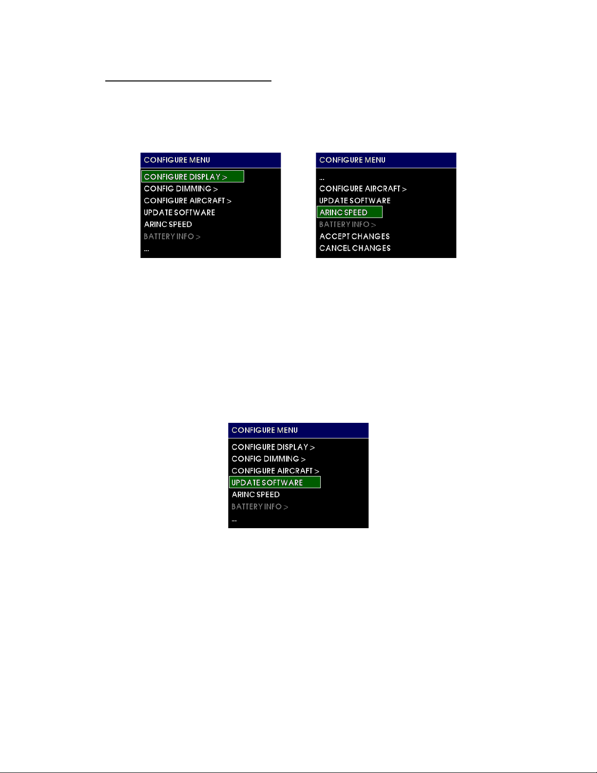
Configuration Mode Actions contain options that do not represent further sub-menus, but
have single settings or initiate ac tions which exit the Configur ation M ode. Figure 4.15
below shows the initial page of the Configuration Menu and the additional options at the
bottom of the Configuration Menu page when scrolling down using the control knob.
FIGURE 4.14
4.5.1 UPDATE SOFTWARE
The UPDATE SOFTARE action initiates the unit to look for a software up d ate that is present
in a USB memory device that has been plugged into the rear of the unit. This action is
unavailable in Emergency Mode (on battery power). If a USB device is not detected or a
valid software update file is not found, a failure message will appear and r eturn back to the
Configuration Menu. If the unit finds a valid software update file, a software update
progress screen will appear. The status screen will indicate when the software update
completes successfully. Acknowledging this comple tion will automatically reset the unit and
return to the Pre-flight Mode, followed by entering Flight Mode. See Figure 4.15.
FIGURE 4.15
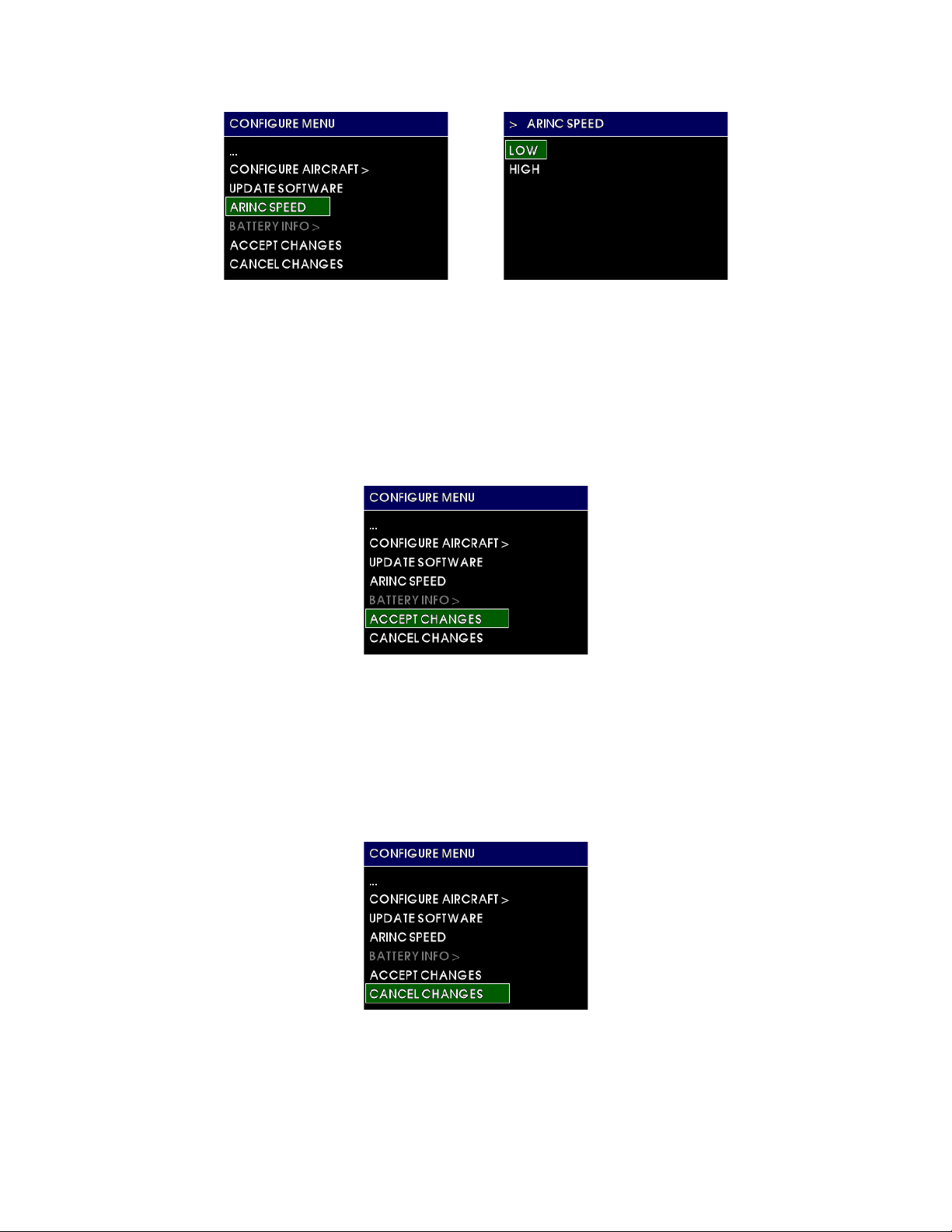
4.5.2 ARINC SPEED
The ARINC SPEED action presents the option to select either LOW or HIGH speed serial
communication data. This option configures the unit’s ability to output ARINC 429
communication data as listed in Table 1.4. Select the option which corresponds to the
receiving equipment’s capability in regards to data speed expectation. See Figure 4.16.
REV. B, October 31, 2012 41 Manual Number 9017782
Page 42
Mid-Continent Instruments and Avionics, Wichita, KS
FIGURE 4.16
4.5.3 ACCEPT CHANGES
When selecting ACCEPT CHANGES, all settings and changes made while in Configuration
Mode are saved into permanent memory and saved to the Configuration Module memory
as well. SETTINGS WILL NOT BE SAVED UNLESS “ACCEPT CHANGES” IS SELECTED
WHEN DONE. After selecting ACCEPT CHANGES, the unit will automatically reset and
return to the Pre-flight Mode, followed by entering Flight Mode. See Figure 4.17.
FIGURE 4.17
4.5.4 CANCEL CHANGES
When selecting CANCEL CHANG ES, any settings or changes made while in Configuration
Mode are canceled. ANY SETTINGS WILL NOT BE SAVED. After selecting CANCEL
CHANGES, the unit will automatically reset and return to the Pre-flight Mode, followed by
entering Flight Mode. See Figure 4.17.
FIGURE 4.18
REV. B, October 31, 2012 42 Manual Number 9017782
Page 43

Mid-Continent Instruments and Avionics, Wichita, KS
SECTION 5 CONFORMANCE
5.1 INSTRUCTIONS FOR CONTINUED AIRWORTHINESS
5.1.1 PRESSURE SYSTEM AND ALTIMETER VERIFICATION
Per federal regulation 14 CFR 91.411, it is required that each static pressure system and each
altimeter have been tested and inspected within the last twenty-four (24) months.
5.1.2 SOFTWARE UPGRADES
Mid-Continent will have, on occasion the need to update software versions on the MD302 for
maintenance, improvements and /or the addition of functionality.
With the MD302’s easy field-upgrade option, the unit does not have to be return ed to the f ac tory,
and in some cases, may not have to be removed from the panel.
Prepare the new software by loading it onto a USB memory device. It is recommended, but not
necessary, that the USB device have no additional files on it. Loosen the screw on the back of the
unit and insert the USB device. By following the procedures in Section 4.5.1, you can load your
software into the MD302. Note the software version before and after this procedure which comes
up on the initial Preflight screen.
5.1.3 BATTERY REPLACEMENT
There should be no regularly schedule maintenance of the True Blue Power Nanophosphate
lithium-ion battery. The battery will recharge itself from aircraft power while in normal mode. A
battery capacity check occurs each time the unit is powered on. If the battery capacity is
determined to be more than 80%, no message is displayed and the battery is good.
If a unit has a battery pack warning , an d the warning persists more than once in a short time, it
can be replaced in the field with minimal effort. By removing two small screws on the rear of the
unit, the battery cover comes off, and the battery is accessible. Pull the battery out using the
handle/strain relief built onto the battery. Replace with a new battery, verify operation and go.
5.1.4 TROUBLESHOOTING
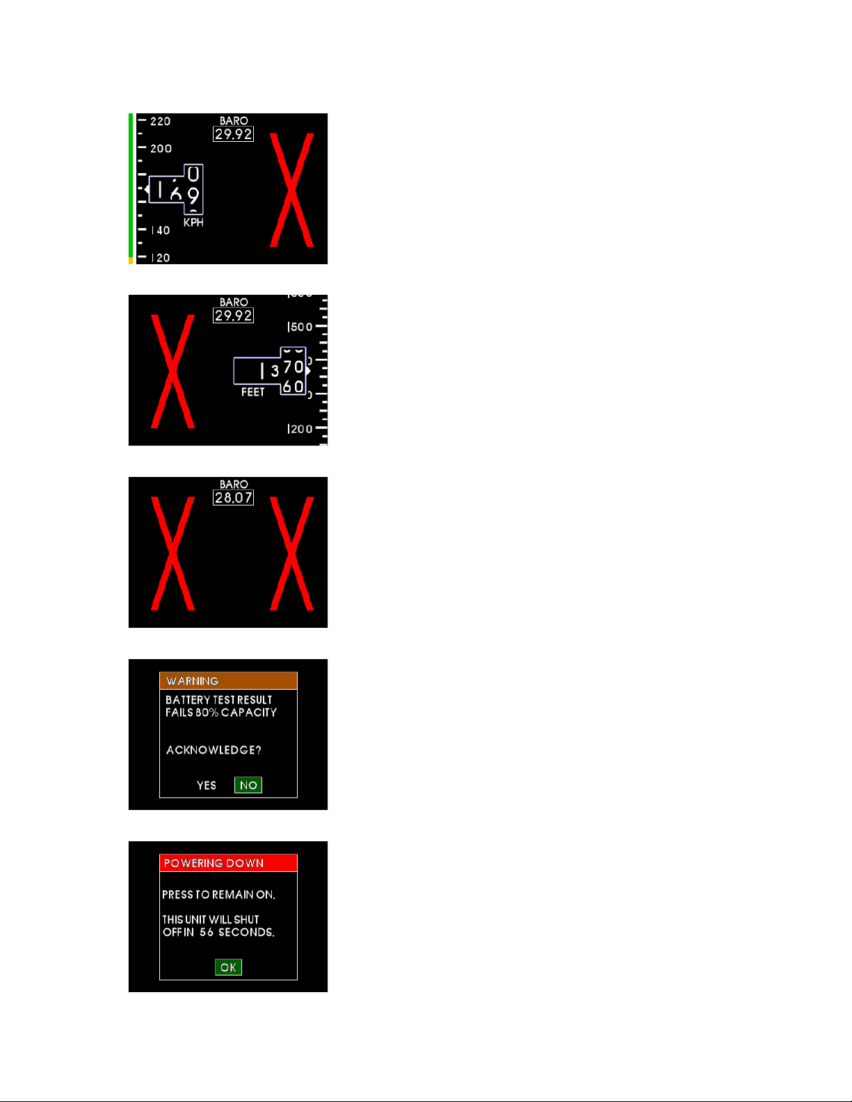
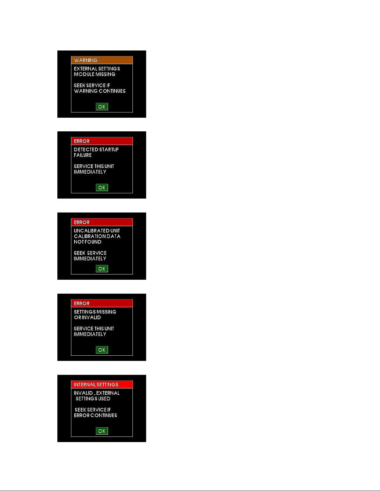
The following Figures and associated descriptions represent warnings or errors and describe the
typical reasons and appropriate response action.
FIGURE 5.1
The attitude display has failed due to exceedance of interal rate
sensors, loss of airspeed or other various reasons. This will
typically self -correct. However, if it does not, immediately have
the unit serviced.
®
REV. B, October 31, 2012 43 Manual Number 9017782
Page 44
Mid-Continent Instruments and Avionics, Wichita, KS
FIGURE 5.2
The altimeter instrument has failed, possibly due to exceedance of
the pressure sensor range. This may self-correct, but if the error
persists, immediately have the unit serviced.
FIGURE 5.3
The airspeed instrument has failed, possibly due to exceedance of
the pressure sensor range. This may self-correct, but if the error
persists, immediately have the unit serviced.
FIGURE 5.4
The airspeed and altimeter display have both failed due to
exceedance of their respective sensor ranges. This may selfcorrect, but if the error persists, service unit immediately.
FIGURE 5.5
Battery failed initial capacity check. This may be due to recent
battery usage without allowing time to recharge. This may also
occur during extreme temperature conditions. User may
acknowledge this error and continue operation, but available
backup power capacity may be less than required minimum levels.
If this warning persists, the battery will need serviced.
FIGURE 5.6
This message is displayed when power is removed at low airspeed
(typical ground condition). The pilot has 60 seconds to confirm to
remain on, otherwise the unit w ill automatically power off to
conserve battery.
REV. B, October 31, 2012 44 Manual Number 9017782
Page 45
Mid-Continent Instruments and Avionics, Wichita, KS
FIGURE 5.7
The configuration module has failed or is not installed properly.
Internal settings will be used. If the configuration module is
installed, it should be serviced immediately.
FIGURE 5.8
Internal failure. Service unit immediately.
FIGURE 5.9
Internal failure. Service unit immediately.
FIGURE 5.10
Internal (unit) and external settings (configuration module) failure.
It is unlikely that both settings would be lost. Try to reconfigure
the unit. Service unit if this error persists.
FIGURE 5.11
Internal (unit) settings were found to be invalid. The configuration
module settings will be copied to internal memory. Service unit if
this error persists.
REV. B, October 31, 2012 45 Manual Number 9017782
Page 46
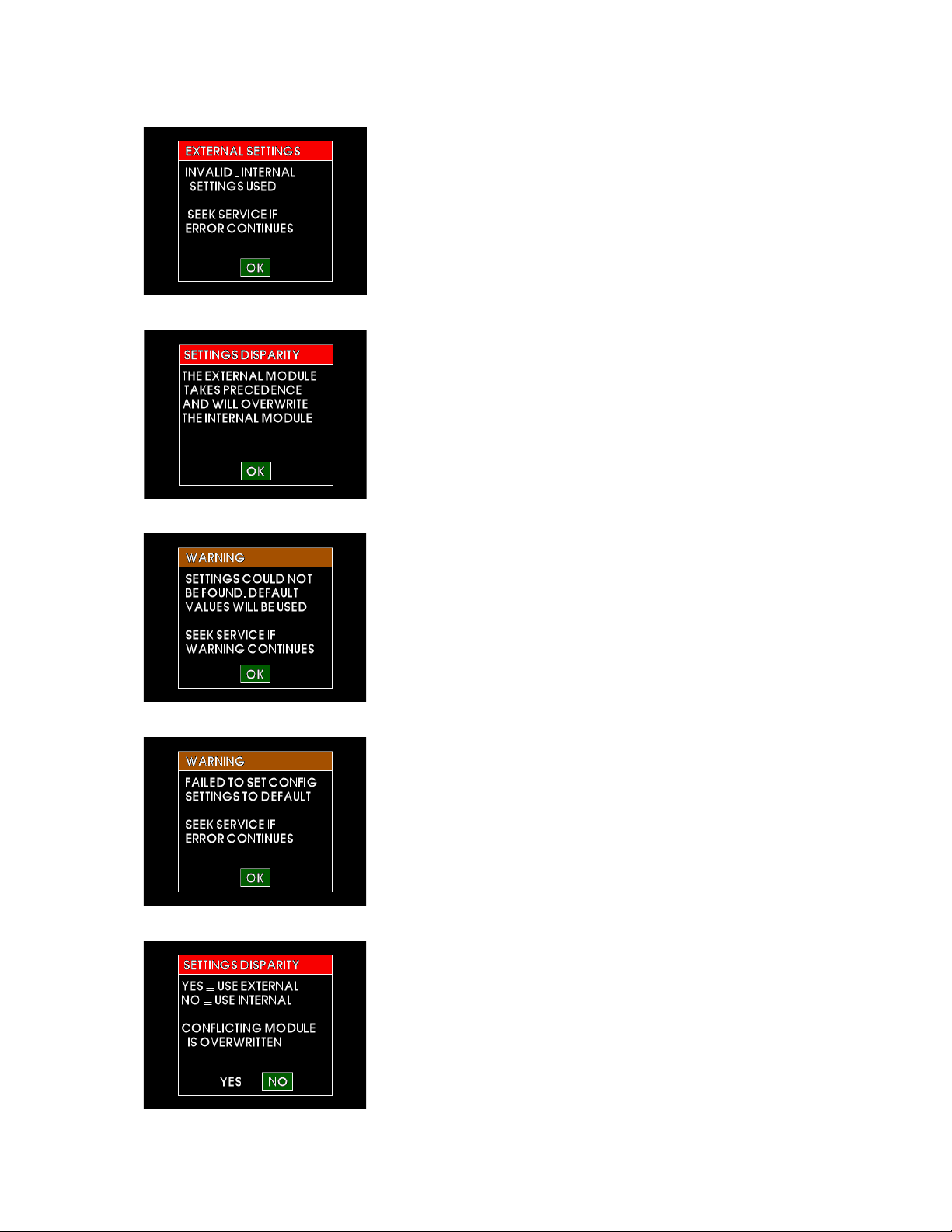
Mid-Continent Instruments and Avionics, Wichita, KS
FIGURE 5.12
External settings (configuration module) were found to be invalid.
The internal settings will be copied to the configuration module
memory. Service unit if this error persists.
FIGURE 5.13
Internal (unit) and external (configuration module) settings were
found to be different. This is typically the result of replacing a unit
in an existing installation. The e xternal settings will be copied to
replace the settings in internal memory.
FIGURE 5.14
In configuration mode, this may be the result of lost settings both
internally and externally. Try to configure the unit. Seek service if
error persists.
FIGURE 5.15
In configuration mode, this may be the result of lost settings and
a failure to initialize memory. Try to restart and configure the unit.
Seek service if error persists.
FIGURE 5.16
Internal (unit) and external (configuration module) settings were
found to be different. This is typically the result of replacing a unit
in an existing installation. In configuration mode, this choice
allows selection of which settings to use.
REV. B, October 31, 2012 46 Manual Number 9017782
Page 47

CONDITIONS
SECTION
DESCRIPTION OF TEST
Temperature and Altitude
Overpressure
4
4.6.3
Category F1
-15,000 ft
Temperature Variation 5 Category S2
Humidity
6
Category A
Operational Shock and
Crash Safety
7
Category B
Vibration
8
Category R, Curves B, B1
(RBB1)
Explosion
9
Category X
Waterproofness
10
Category X
Fluids
11
Category X
Sand and Dust
12
Category X
Fungus
13
Category X
Salt Spray
14
Category X
Magnetic Effect
15
Category Z
Power Input
16
Category Z(XX)
Voltage Spike
17
Category A
Audio Frequency Conducted
Susceptibility
18
Category Z
Induced Signal Susceptibility
19
Category ZC
Radio Frequency Susceptibility
20
Category W (conducted)
[WF]
Emission of Radio Freq Energy
21
Category P
Lightning Induced Transient
22
Category B3 (pin injection)
[B3H33]
Lightning Direct Effects
23
Category X
Icing
24
Category X
ESD
25
Category A
Fire, F l ammab i lity
26
Category X
REMARKS:
Sections 4: Category F1 complete with additional excursions as listed for Sections 4.5.1, 4.5.2, 4.6.2, and 4.6.3.
Mid-Continent Instruments and Avionics, Wichita, KS
5.2 ENVIRONMENTAL QUALIFICATION STATEMENT
NOMENCLATURE: 2-inch Standby Attitude Module
MODEL NUMBER: MD302 Series PART NUMBER: 6420302-( )
TSO NUMBERS: C2d (Type B), C3e, C4c, C10b, C106, C113a, C179a
MANUFACTURERS SPECIF I CATIONS:
Minimum Performance Specifications:TS302 (XX/XX/XX), TDS302 (XX/XX/XX)
Qualification Test Reports: QTR1201 (10/04/05)
MANUFACTURER: Mid-Continent Instrument Co., Inc.
ADDRESS: 9400 E. 34th St. North, Wichita, KS 67226, USA
RTCA DO-160: Rev G, dtd 12/08/10 DATES TESTED:06/12-09/12
Low Temperature
High Temperature
Decompression
4.5.1
4.5.2
4.6.2
Short and Normal Operating L ow Temp = -30C
Short and Normal Operating High Temp = +70C
Altitude = 55K
Category F (radiated)
Susceptibility
Category H33 (cable bundle)
REV. B, October 31, 2012 47 Manual Number 9017782
 Loading...