


PRO Series Live Audio Systems
Owner’s Manual
Midas Klark Teknik Limited,
Klark Industrial Park,
Walter Nash Road,
Kidderminster.
Worcestershire.
DY11 7HJ.
England.
Tel: +44 1562 741515
Fax: +44 1562 745371
Email: info@midasklarkteknik.com
Website: www.midasconsoles.com
PRO Series Live Audio Systems — Owner’s Manual
DOC02-PROSERIES Issue A — September 2010
In line with the company’s policy of continual improvement, specifications and function may be
subject to change without notice. This Owner’s Manual was correct at the time of writing. E&OE.
© Red Chip Company Ltd.


IMPORTANT SAFETY INSTRUCTIONS
The lightning flash with arrowhead symbol within an equilateral triangle is
intended to alert the user to the presence of uninsulated “dangerous voltage”
within the product's enclosure that may be of sufficient magnitude to constitute a
risk of electric shock to persons.
The exclamation point within an equilateral triangle is intended to alert the user
to the presence of important operating and maintenance (servicing) instructions
in the literature accompanying the product.
1 Read these instructions.
2 Keep these instructions.
3 Heed all warnings.
4 Follow all instructions.
5 Do not use this apparatus near water.
6 Clean only with a dry cloth.
7 Do not block any of the ventilation
openings. Install in accordance with the
manufacturer’s instructions.
8 Do not install near any heat sources such
as radiators, heat registers, stoves, or
other apparatus (including amplifiers) that
produce heat.
9 Do not defeat the safety purpose of the
polarized or grounding-type plug. A
polarized plug has two blades with one
wider than the other. A grounding type
plug has two blades and a third grounding
prong. The wide blade or the third prong
are provided for your safety. If the
provided plug does not fit into your outlet,
consult an electrician for replacement of
the obsolete outlet.
10 Protect the power cord from being walked
on or pinched particularly at plugs,
convenience receptacles and the point
where they exit from the apparatus.
11 Only use attachments/accessories
specified by the manufacturer.
12 Use only with the cart, stand,
tripod, bracket, or table
specified by the
manufacturer, or sold with
the apparatus. When a cart
is used, use caution when moving the
cart/apparatus combination to avoid injury
from tip-over.
13 Unplug this apparatus during lightning
storms or when unused for long periods of
time.
14 Refer all servicing to qualified personnel.
Servicing is required when the apparatus
has been damaged in any way, such as
power-supply cord or plug is damaged,
liquid has been spilled or objects have
fallen into the apparatus, the apparatus
has been exposed to rain or moisture,
does not operate normally, or has been
dropped.
15 Use the mains plug to disconnect the
apparatus from the mains.
16 Warning: To reduce the risk of fire or
electric shock, do not expose this
apparatus to rain or moisture.
17 Warning: Do not expose this
equipment to dripping or splashing
and ensure that no objects filled with
liquids, such as vases, are placed on
the equipment.
18 Warning: The mains plug of the power
supply cord shall remain readily
operable.

INSTRUCTIONS DE SÉCURITÉ IMPORTANTES
Le symbole représentant un éclair fléché dans un triangle équilatéral a pour but
d'alerter l'utilisateur de la présence d'une "tension dangereuse" non isolée à
l'intérieur du boîtier, pouvant être d'une force suffisante pour constituer un risque
d'électrocution.
Le point d'exclamation dans un triangle équilatéral a pour but d'alerter
l'utilisateur de la présence d'instructions importantes concernant le
fonctionnement et la maintenance, dans la documentation qui accompagne
l'appareil.
1 Veuillez lire ces instructions.
2 Conservez ces instructions.
3 Respectez toutes les consignes de
sécurité.
4 Suivez scrupuleusement toutes les
instructions.
5 N'utilisez pas cet appareil près d'un point
d'eau.
6 Utilisez uniquement un chiffon sec pour le
nettoyer.
7 N'obstruez aucune des ouïes de
ventilation. Installez-le en respectant les
instructions du fabricant.
8 Ne l'installez pas près de sources de
chaleur tels que radiateurs, panneaux
chauffants, étuves, ou autres appareils
produisant de la chaleur (dont les
amplificateurs).
9 Ne pas utiliser d'adaptateur pour
supprimer la prise de terre des prises à
trois fiches. Si la prise fournie ne peut pas
être branchée dans la prise électrique,
adressez-vous à un électricen qui
remplacera la prise obsolète.
10 Protégez le cordon secteur afin que l'on ne
marche pas dessus et qu'il ne soit pas
pincé, surtout au niveau des prises, ou à
l'endroit où il sort de l'appareil.
11 Utilisez exclusivement des fixations et des
accessoires recommandés par le fabricant.
12 Utilisez l'appareil uniquement
avec le chariot, le trépied, le
support ou la table spécifiés
par le fabricant, ou vendus
avec l'appareil. Si un chariot
est utilisé, prenez toutes les précautions
nécessaires lorsque vous devez déplacer
l'ensemble (chariot et appareil) afin qu'ils
ne se renversent pas.
13 Débranchez l'appareil en période d'orage
ou s'il doit rester inutilisé pendant
longtemps.
14 Confiez toutes les réparations et
interventions à un personnel qualifié. Une
intervention est nécessaire si l'appareil a
été endommagé d'une façon ou d'une
autre, si son cordon ou sa prise secteur
ont été endommagés, si du liquide a été
renversé ou si des objets sont tombés à
l'intérieur, ou encore si l'appareil a été
exposé à la pluie ou à l'humidité, s'il ne
fonctionne pas normalement, ou s'il est
tombé.
15 Débrancher l'appareil du réseau électrique
par la prise de secteur.
16 Avertissement : afin de réduire le
risque d'incendie ou de choc
électrique, ne pas exposer cet
appareil à la pluie ou à de l'humidité.
17 Avertissement : n'exposez pas cet
équipement aux éclaboussures et
veillez à ce qu'aucun récipient rempli
de liquide, verre ou vase, ne soit posé
dessus.
18 Avertissement : la prise secteur doit
toujours rester directement
accessible.

PRO6 EC-Declaration of Conformity
Midas
DOC04-PRO3ECDOC Rev. A
EC-Declaration of Conformity
The undersigned, representing the following manufacturer
Manufacturer: Address:
Midas Klark Teknik Ltd. Klark Industrial Park, Walter Nash Road,
Kidderminster. Worcestershire. DY11 7HJ.
hereby declares that the following product
Product Type Number Product Description Nominal Voltage(s) Current Freq.
PRO3 Control Centre
115V AC
230V AC
2.9A
1.5A
50/60Hz
is in conformity with the regulations of the following marked EC-directives and bears the
-mark accordingly
reference number title
2004/108/EC EMC Directive (EMC)
2006/95/EC Low-Voltage Directive (LVD)
The conformity of the product with EC Directives for use in environment E4 is provided by compliance with
the following standards:
Standards/date:
Applied Electrical Safety test standards:
reference number title
EN 60065:2002
Audio, video and similar electronic apparatus. Safety requirements.
Applied EMC emission test standards:
ref. no. title
EN 55103-1:1996
Class A
EN 55103-1 Annex A: Radiated
magnetic disturbance, 50Hz-50kHz
CISPR 22: Radiated disturbance,
30-1000MHz
CISPR 22: Conducted disturbance,
ac & signal ports
CISPR 16: Discontinuous
disturbance
EN 61000-3-2:2000 Mains
harmonics
EN 61000-3-3:1995 Mains voltage
flicker
Applied EMC immunity test standards:
ref. no. title
EN 61000-4-2:1995 Electrostatic
discharge
EN 55103-2:1996
Class A
EN 61000-4-3:1996: Radiated RF
disturbance, 80-1000MHz
EN 55103-2 Annex A: Magnetic LF
disturbance, 50Hz–10kHz
EN 61000-4-4:1995: Fast transient
bursts, ac & signal ports
EN 61000-4-5:1995: Surge, ac port
EN 61000-4-6:1996: Conducted RF
field, ac & signal ports
EN 61000-4-11:1994: Mains voltage
dips and interruptions
Place, date: Kidderminster, UK
18th August 2010
General Manager AVP, Product Development
Printed name: John Oakley Printed name: Alex Cooper


PRO6 EC-Declaration of Conformity
Midas
DOC04-PRO6ECDOC Rev. B
EC-Declaration of Conformity
The undersigned, representing the following manufacturer
Manufacturer: Address:
Midas Klark Teknik Ltd. Klark Industrial Park, Walter Nash Road,
Kidderminster. Worcestershire. DY11 7HJ.
hereby declares that the following product
Product Type Number Product Description Nominal Voltage(s) Current Freq.
PRO6 Control Centre
115V AC
230V AC
2.9A
1.5A
50/60Hz
is in conformity with the regulations of the following marked EC-directives and bears the
-mark accordingly
reference number title
2004/108/EC EMC Directive (EMC)
2006/95/EC Low-Voltage Directive (LVD)
The conformity of the product with EC Directives for use in environment E4 is provided by compliance with
the following standards:
Standards/date:
Applied Electrical Safety test standards:
reference number title
EN 60065:2002
Audio, video and similar electronic apparatus. Safety requirements.
Applied EMC emission test standards:
ref. no. title
EN 55103-1:1996
Class A
EN 55103-1 Annex A: Radiated
magnetic disturbance, 50Hz-50kHz
CISPR 22: Radiated disturbance,
30-1000MHz
CISPR 22: Conducted disturbance,
ac & signal ports
CISPR 16: Discontinuous
disturbance
EN 61000-3-2:2000 Mains
harmonics
EN 61000-3-3:1995 Mains voltage
flicker
Applied EMC immunity test standards:
ref. no. title
EN 61000-4-2:1995 Electrostatic
discharge
EN 55103-2:1996
Class A
EN 61000-4-3:1996: Radiated RF
disturbance, 80-1000MHz
EN 55103-2 Annex A: Magnetic LF
disturbance, 50Hz–10kHz
EN 61000-4-4:1995: Fast transient
bursts, ac & signal ports
EN 61000-4-5:1995: Surge, ac port
EN 61000-4-6:1996: Conducted RF
field, ac & signal ports
EN 61000-4-11:1994: Mains voltage
dips and interruptions
Place, date: Kidderminster, UK
14th June 2010
General Manager AVP, Product Development
Printed name: John Oakley Printed name: Alex Cooper


PRO9 EC-Declaration of Conformity
Midas
DOC04-PRO9ECDOC Rev. A
EC-Declaration of Conformity
The undersigned, representing the following manufacturer
Manufacturer: Address:
Midas Klark Teknik Ltd. Klark Industrial Park, Walter Nash Road,
Kidderminster. Worcestershire. DY11 7HJ.
hereby declares that the following product
Product Type Number Product Description Nominal Voltage(s) Current Freq.
PRO9 Control Centre
115V AC
230V AC
2.9A
1.5A
50/60Hz
is in conformity with the regulations of the following marked EC-directives and bears the
-mark accordingly
reference number title
2004/108/EC EMC Directive (EMC)
2006/95/EC Low-Voltage Directive (LVD)
The conformity of the product with EC Directives for use in environment E4 is provided by compliance with
the following standards:
Standards/date:
Applied Electrical Safety test standards:
reference number title
EN 60065:2002
Audio, video and similar electronic apparatus. Safety requirements.
Applied EMC emission test standards:
ref. no. title
EN 55103-1:1996
Class A
EN 55103-1 Annex A: Radiated
magnetic disturbance, 50Hz-50kHz
CISPR 22: Radiated disturbance,
30-1000MHz
CISPR 22: Conducted disturbance,
ac & signal ports
CISPR 16: Discontinuous
disturbance
EN 61000-3-2:2000 Mains
harmonics
EN 61000-3-3:1995 Mains voltage
flicker
Applied EMC immunity test standards:
ref. no. title
EN 61000-4-2:1995 Electrostatic
discharge
EN 55103-2:1996
Class A
EN 61000-4-3:1996: Radiated RF
disturbance, 80-1000MHz
EN 55103-2 Annex A: Magnetic LF
disturbance, 50Hz–10kHz
EN 61000-4-4:1995: Fast transient
bursts, ac & signal ports
EN 61000-4-5:1995: Surge, ac port
EN 61000-4-6:1996: Conducted RF
field, ac & signal ports
EN 61000-4-11:1994: Mains voltage
dips and interruptions
Place, date: Kidderminster, UK
18th August 2010
General Manager AVP, Product Development
Printed name: John Oakley Printed name: Alex Cooper


Licences
The following are the license agreements applicable to the Midas Digital Equipment.
End-User Licence Agreement for Midas™ and Klark Teknik™ Software
IMPORTANT - Please read this document carefully before using this Midas™ or
Klark Teknik™ Product. This is an agreement governing your use of software or
other machine instructions already installed on this Midas™ or Klark Teknik™
Product, as well as other software that we provide for installation on this Product.
The Midas™ or Klark Teknik™ Product will not operate in accordance with its
documentation without this software.
THIS AGREEMENT ("AGREEMENT" OR "LICENCE") STATES THE TERMS AND CONDITIONS UPON WHICH
MIDAS KLARK TEKNIK LIMITED ("COMPANY") OFFERS TO LICENSE THE INSTALLED FIRMWARE,
SOFTWARE AND/OR PROGRAMS ("the SOFTWARE") WITH THE MIDAS™ OR KLARK TEKNIK™ CONSOLE
OR SIGNAL PROCESSING PRODUCT ("PRODUCT") IN WHICH IT HAS BEEN INSTALLED BY, OR FOR
WHICH IT IS PROVIDED BY, THE COMPANY. BY USING THIS PRODUCT YOU WILL BE AGREEING TO
BECOME BOUND BY THE TERMS OF THIS LICENCE. IF YOU DO NOT AGREE TO THE TERMS OF THIS
LICENCE, DO NOT USE THIS PRODUCT AND PROMPTLY RETURN THE PRODUCT TO THE PLACE WHERE
YOU OBTAINED IT FOR A FULL REFUND. You agree to notify any persons whom you permit to operate
this Product of the terms of this Licence, and to require them to comply with these terms.
The Software is licensed, not sold, to you for use only under the terms of this Licence, and the
Company reserves all rights not expressly granted to you. The Company retains ownership of all copies
of the Software itself, and all proprietary parts of it, including those stored on or in the Product.
1. Licence: Subject to the terms and conditions of this agreement, the Company grants you, and
other persons you permit to operate the Product, a personal, limited, non-exclusive,
non-transferable licence to use the Software only on the single Product unit in which it has been
installed.
2. Restrictions: (a) The Software, and the accompanying written materials, are copyrighted and
contain trade secrets and other proprietary matter, including confidential information relating to
the specifications and performance characteristics of this Product. Save for such elements as
may be licensed to the Company, as described in paragraph 5, all rights to copyrights, trade
marks and trade secrets in the Software, or any modifications to it, are owned by the Company.
Unauthorised use or copying of the Company's proprietary Software, or any portion thereof, or
copying of those written materials, is prohibited. (b) You may not create, market, distribute, or
transfer copies of the Company's proprietary Software, or any part of it, to others, or duplicate,
rent, lease or loan that Software, or any part of it, except that you may transfer that Software
installed in this Product in conjunction with the sale, transfer, loan, rent or lease of this Product,
and subject at all times to this Licence. YOU MAY NOT REVERSE ENGINEER, DECOMPILE,
DISASSEMBLE, EXTRACT OR SEPARAT E OUT, MODIFY, ADAPT, PORT, OR TRANSLATE THE
SOFTWARE, DERIVE THE SOURCE CODE OF THE SOFTWARE OR CREATE DERIVATIVE WORKS
BASED ON THE SOFTWARE OR ANY ACCOMPANYING WRITTEN MA TERIALS, save as is allowed by
licences pertaining to component parts of the Software which are licensed by third parties, as
described under paragraph 5, or otherwise by law. (c) In the event you violate any term of this
Licence, all rights granted herein will automatically and immediately terminate and you must stop
using the Software and destroy any copies of the Software.
3. Limited Warranty: Subject to your installation of any Software updates issued by the Compan y
as described herein, and the condition below, the Company warrants that the Software will
operate in compliance with the Software's material specifications and documentation for a period
of 90 days from your purchase of this Product. The Software is provided "as is" and the Company
does not warrant that the operation of the Software will meet your requirements or operate free
from error. To the greatest extent permissible by law, the Company DISCLAIMS ALL
WARRANTIES AND CONDITIONS, EITHER EXPRESS OR IMPLIED, INCLUDING THE WARRANTIES
OF MERCHANTABILITY, FITNESS FOR A PARTICULAR PURPOSE, NON-INFRINGEMENT OF THIRD
PARTY RIGHTS OR CAPABILITY OF CORRECTLY PROCESSING PROVIDING AND/OR RECEIVING

DATE INFORMATION. You understand that the Company may update or revise the Software but
in so doing incurs no obligation to furnish such updates to you. However , the Company may in its
discretion make updates available from time to time upon such terms and conditions as it shall
determine. It is a condition of the above warranty that you install any such Software updates, as
may be issued from time to time by the Company for the Software, in accordance with the
Company's instructions, and if you do not do so such warranty will cease to apply. You may view
current Software updates at http://www.klarkteknik.com and http://www.midasconsoles.com.
4. Limited Liability: THE ENTIRE RISK ARISING OUT OF YOUR USE OR PERFORMANCE OF THE
SOFTWARE REMAINS WITH YOU. THE LIABILITY OF THE COMPANY FOR ANY CLAIMS ARISING
OUT OF THIS LICENCE AND/OR BASED UPON THE SOFTWARE, REGARDLESS OF THE FORM OF
ACTION, AND INCLUDING WORK STOPPAGE, PRODUCT FAILURE OF MALFUNCTION OR ANY
OTHER COMMERCIAL LOSS OR DAMAGE, SHALL NOT EXCEED THE COST OF THE LICENCE FEE
FOR THE SOFTWARE OR THE COST OF THIS PRODUCT. SUBJECT TO THE PROVISIONS OF
APPLICABLE LAW, IN NO EVENT SHALL THE COMPANY BE LIABLE FOR ANY LOSS OF DATA, LOST
OPPORTUNITY OR PROFITS, COST OF COVER OR SPECIAL, INCIDENTAL, CONSEQUENTIAL, OR
INDIRECT DAMAGES, EVEN IF YOU ADVISE THE COMPANY OF THE POSSIBILITY OF SUCH
DAMAGES. THIS IS A FUNDAMENTAL TERM OF THIS AGREEMENT AND YOU ACKNOWLEDGE
THAT THE AMOUNT YOU PAID FOR THE SOFTWARE AND/OR THE PRODUCT REFLECTS THIS
ALLOCATION OF RISK. NOTHING IN THIS PARAGRAPH PURPORTS TO EXCLUDE OR LIMIT THE
COMPANY'S LIABILITY FOR DEATH OR PERSONAL INJURY CAUSED BY NEGLIGENCE OR ANY
OTHER LIABILITY WHICH CANNOT BE EXCLUDED OR LIMITED BY LAW.
5. Other Third-Party Computer Programs: As referred to herein, the term "Software" refers
only to proprietary Midas™ or Klark Teknik™ software, owned by the Company, that has been
provided to you for installation on, or already installed in, a Product. In addition to the Softw are,
you may have also been provided, at no additional charge, with a version of the widely-available
GNU Linux Operating System, which is a modular operating system made up of hundreds of
individual software components, each of which was written, and the copyright and other rights in
which are owned individually, by various parties (collectively, "the GNU Linux Programs"). Each
component has its own applicable end user li cence agreement, and many of these agreements
permit you to copy, modify, and redistribute the applicable software, but you must review the
on-line documentation that shares a directory or otherwise accompanies each of the GNU Linux
Programs provided to you for the specific terms and conditions. Nothing in this Licence limits
your rights under, or grants you rights that supersede, the terms of any other applicable end user
licence agreement. If you wish to receive a computer-readable copy of the source code for any
of the GNU Linux Programs that have been provided with your Midas™ or Klark Teknik™ Product,
send a cheque or money order (no cash accepted), your address and [£10.00] to cover the cost
of optical media, postage and handling, to:
Midas Klark Teknik Limited
ATTN: Linux Programs CD for Midas™/Klark Teknik™
Walter Nash Road,
Kidderminster.
Worcestershire.
DY11 7HJ.
England.
In your request, indicate your Product's name and model number, serial number and
version/release information. In your request, also indicate the relevant Software version/release
information. This offer, made pursuant to the GNU Linux Programs' end user licence agreements,
may expire according to the terms of those agreements, in which case your cheque will be
returned to you or destroyed at our option. Please note that the GNU Linux Programs that may
be available to you under this offer consists of the GNU Linux Operating System components only
and none of the proprietary application software developed by Midas or Klark Teknik is included.
Other updated Linux distributions containing application software are widely available from a
variety of Internet sources, and are often available at minimal or no cost.
6. Termination: This Licence will terminate immediately if you violate any of the Licence terms.
Upon termination you must discontinue use of the Software, and either destroy, erase or return
to Company all copies of the Software in your possession, custody or control, including those in
or on the Product.
7. General: This Licence constitutes the entire agreement between you and the Company with
respect to this Software and, save in the case of fraud, supersedes any other communication
(including advertising). Company reserves all rights not expressly granted to y ou in this licence.
If any provision of this Licence is held unenforceable, that provision shall be enforced to the
maximum extent permissible so as to give effect the intent of this Licence, and the remainder of
this Licence shall continue in full force and effect. This Licence shall be governed by English law

and the Courts of England and Wales will have exclusive jurisdiction to hear and decide any
dispute concerning it or its formation. No breach by you of any provision of this Licence shall be
waived or discharged except with the express written consent of the Company and no failure or
delay by the Company to exercise any of its rights under this Licence shall operate as a waiver
thereof and no single or partial exercise of any such right shall prevent any other or further
exercise of that or any other right. You acknowledge that the Company could be irreparably
damaged if the terms of this Licence were not specifically enforced, and agree that the Company
may seek appropriate equitable remedies with respect to breaches of this Licence, including
injunctive relief, in addition to such other remedies as the Company may otherwise have
available to it under applicable laws.
GNU General Public License (GPL)
For details of the Third Party Software License Attribution, Copyright and Terms and Conditions and
Notices, and the GNU LESSER GENERAL PUBLIC LICENSE, see the Midas Digital Equipment GNU
General Public License (GPL) Booklet part number DOC04-GPL issue A.


xvii
Precautions
Before installing, setting up or operating this equipment make sure you have read and
fully understand all of this section and the “IMPORTANT SAFETY INSTRUCTIONS” at the
front of this document.
This equipment is supplied by a mains voltage that can cause electric shock injury!
The following must be observed in order to maintain safety and electromagnetic compatibility (EMC)
performance.
Safety warnings
Signal 0V is connected internally to the
chassis.
To completely isolate this equipment from
the AC mains, while observing full safety
precautions (see “Power”), switch off the
isolator switch (above the mains power
sockets on rear of control centre) and then
switch off the mains at the three mains
outlets. Unplug the three mains leads from
the rear of the control centre.
To avoid electrical shock do not remove
covers.
General precautions
In the event of ground loop problems,
disconnect the signal screen at one end of the
connecting cables. Note that this can only be
done when the equipment is used within a
balanced system.
Do not remove, hide or deface any warnings or
cautions.
Power
The power supplies contain LETHAL VOLTAGES
greatly in excess of the mains voltage and its
rails can produce extremely large currents that
could burn out equipment and wiring if shorted.
distributed so as to meet local safety
regulations.
A Volex locking type plug is fitted on each
supplied mains cable, which plugs into a mains
IEC connector on the equipment. When fitted
properly the Volex plug locks into place,
preventing it from working loose, or being
inadvertently knocked loose or pulled out. To fit
a Volex plug, insert it into the mains IEC
connector and push it in until it locks in place.
Then, check to make sure it is locked in place.
To remove it, release its locking device and then
pull it out. When fitting or removing a Volex
plug, always hold the plug itself and never use
the cable, as this may damage it.
During operation of the control centre, a
minimum of two of its three mains inlets must
be connected and supplying power.
When removing the equipment’s electric plugs
from the outlets, always hold the plug itself and
not the cable. Pulling out the plug by the cable
can damage it.
Never insert or remove an electric plug with wet
hands.
Do not connect/disconnect a mains power
connector to/from the control centre while
power is being applied to it. Switch the power
off first.
Before switching the control centre on or off,
make sure that all monitor loudspeaker power
amplifiers are turned off or muted.
The internal power supplies are of the switch
mode type that automatically sense the
incoming mains voltage and will work where the
nominal voltage is in the range 100VAC to
240VAC.
Each mains inlet is to be sourced from its own
separate wall-mounted mains outlet socket.
Otherwise, their mains sources must be suitably
PRO Series Live Audio Systems
Owner’s Manual

xviii Precautions
Handling the equipment
Completely isolate the equipment electrically
and disconnect all cables from the equipment
before moving it.
When lifting or moving the equipment, always
take its size and weight into consideration. Use
suitable lifting equipment or transporting gear,
or sufficient additional personnel.
Do not insert your fingers or hands in any gaps
or openings on the equipment, for example,
vents.
Do not press or rub on the sensitive surface of
the GUI screens.
If the glass of the GUI screen is broken, liquid
crystals shouldn’t leak through the break due to
the surface tension of the thin layer and the
type of construction of the LCD panel. However,
in the unlikely event that you do make contact
with this substance, wash it out with soap.
Installation
Before installing the equipment:
• Make sure the equipment is correctly
connected to the protective earth conductor
of the mains voltage supply of the system
installation through the mains leads.
• Power to the equipment must be via a fused
spur(s).
• Power plugs must be inserted in socket
outlets provided with protective earth
contacts. The electrical supply at the socket
outlets must provide appropriate
over-current protection.
• Both the mains supply and the quality of
earthing must be adequate for the
equipment.
• Before connecting up the equipment, check
that the mains power supply voltage rating
corresponds with the local mains power
supply . The rating of the mains power supply
voltage is printed on the equipment.
Location
Ideally a cool area is preferred, away from
power distribution equipment or other potential
sources of interference.
Do not install the equipment in places of poor
ventilation.
Do not install this equipment in a location
subjected to excessive heat, dust or mechanical
vibration. Allow for adequate ventilation around
the equipment, making sure that its fans and
vents are not obstructed. Whenever possible,
keep the equipment out of direct sunlight.
Do not place the equipment in an unstable
condition where it might accidentally fall over.
Make sure that the mains voltage and fuse
rating information of the equipment will be
visible after installation.
Audio connections
To ensure the correct and reliable operation of
your equipment, only high quality, balanced,
screened, twisted pair audio cable should be
used.
XLR connector shells should be of metal
construction so that they provide a screen when
connected to the control centre and, where
appropriate, they should have Pin 1 connected
to the cable screen.
Electrostatic discharge
(ESD) precautions
Observe full electrostatic discharge
(ESD) — also known as “anti-static”
— precautions when carrying out
procedures in this manual that are
accompanied by the ESD Susceptibility Symbol
(shown above). This caution symbol shows you
that ESD damage may be caused to items
unless proper ESD precautions are taken, which
include the following practices:
• Keep the work area free from plastic, vinyl or
styrofoam.
• Wear an anti-static wrist strap.
• Discharge personal static before handling
devices.
• Ground the work surface.
• Avoid touching ESD-sensitive devices.
Radio frequency
interference—Class A
device
This equipment has been tested and found to
comply with the limits for a Class A digital
device, pursuant to Part 15 of the FCC Rules.
These limits are designed to provide reasonable
protection against harmful interference when
the equipment is operated in a commercial
environment. This equipment generates, uses,
and can radiate radio frequency energy and, if
PRO Series Live Audio Systems
Owner’s Manual

Precautions xix
not installed and used in accordance with the
instruction manual, may cause harmful
interference to radio communications.
Operation of this equipment in a residential area
is likely to cause harmful interference in which
case the user will be required to correct the
interference at his own expense.
Electric fields
Caution:
In accordance with Part 15 of the FCC
Rules & Regulations, “… changes or
modifications not expressly approved by
the party responsible for compliance could
void the user's authority to operate the
equipment.”
Should this product be used in an
electromagnetic field that is amplitude
modulated by an audio frequency signal (20Hz
to 20kHz), the signal to noise ratio may be
degraded. Degradation of up to 60dB at a
frequency corresponding to the modulation
signal may be experienced under extreme
conditions (3V/m, 90% modulation).
Safety equipment
Never remove, for example, covers, housings or
any other safety guards. Do not operate the
equipment or any of its parts if safety guards
are ineffective or their effectiveness has been
reduced.
Optional equipment
Unless advised otherwise, optional equipment
must only be installed by service personnel and
in accordance with the appropriate assembly
and usage regulations.
Special accessories
To comply with part 15 of the FCC Rules, any
special accessories (that is, items that cannot be
readily obtained from multiple retail outlets)
supplied with this equipment must be used with
this equipment; do not use any alternatives as
they may not fulfil the RF requirement.
PRO Series Live Audio Systems
Owner’s Manual

xx Precautions
PRO Series Live Audio Systems
Owner’s Manual

xxi
Recommandations
Avant l'installation, la mise au point ou l'exploitation de cet équipement, veiller à lire
attentivement et à comprendre l'intégralité de ce chapitre et la partie "CONSIGNES DE
SÉCURITÉ IMPORTANTES" au début de ce manuel.
Cet équipement est alimenté par une tension de secteur pouvant provoquer des blessures par choc
électrique !
Les points suivants doivent être observés afin de maintenir la sécurité et une compatibilité
électromagnétique (CEM) correcte.
Avertissements de sécurité
Une tension 0V de signal est raccordée en
interne au châssis.
Afin de déconnecter complètement cet
appareil du secteur CA, tout en observant
les précautions de sécurité (voir
“Puissance”), couper le sectionneur (audessus des prises secteur sur le panneau
arrière du centre de contrôle), puis couper
le secteur aux trois socles de secteur.
Isoler l'appareil en débranchant les trois
câbles de secteur du panneau arrière du
centre de contrôle.
Afin d'éviter un choc électrique, ne pas
retirer les couvercles.
Recommandations
générales
En cas de problème de boucle de terre,
débrancher le blindage de signal à une
extrémité des câbles de raccordement. Il
convient de noter que cela n'est faisable que si
l'équipement est utilisé dans un système
équilibré.
Ne pas retirer, cacher ni dégrader les
avertissements ou les mises en garde.
Puissance
Les alimentations électriques contiennent des
TENSIONS LÉTALES largement supérieures à la
tension de secteur et les barres peuvent
produire des courants extrêmement élev és
capables de griller l'équipement et le câblage en
cas de court-circuit.
Les alimentations électriques internes sont des
alimentations à découpage détectant
automatiquement la tension de secteur d'entrée
et fonctionnant lorsque la tension nominale se
trouve dans la plage de 100 VCA à 240 VCA.
Chaque prise de secteur doit être raccordée à
son propre socle mural séparé. Sans quoi, les
alimentations de secteur doivent être
correctement distribuées conformément aux
réglementations locales de sécurité.
Chaque câble d'alimentation fourni est équipé
d'une fiche Volex verrouillable qui se branche
dans une prise connecteur CEI sur l'appareil.
Lorsqu'elle est montée correctement la fiche
Volex se verrouille dans son logement,
l'empêchant de se desserrer ou d'être
déconnectée par inadvertance. Pour brancher
une fiche Volex, l'insérer dans la prise
connecteur secteur CEI et la pousser jusqu'à ce
qu'elle se verrouille dans son logement. Penser
ensuite à vérifier qu'elle soit correctement
verrouillée. Pour l'enlever, libérer son dispositif
de verrouillage pour ensuite la tirer. Lors de la
connection ou déconnection d'une fiche Volex,
toujours saisir la fiche elle-même et ne jamais
utiliser le câble, car cela pourrait l'endommager.
Pendant le fonctionnement du centre du contrôle
un minimum de deux de ses trois entrées
secteur doivent être connectés et alimentation.
Pour débrancher les cordons d'alimentation de
l'équipement des prises murales, tenir toujours
la prise et non le câble. Tirer la prise par le câble
peut l'endommager.
Ne jamais brancher ni débrancher une prise
électrique avec des mains humides.
Ne jamais brancher/débrancher un connecteur
de secteur au/du centre de contrôle s'il est sous
tension. Mettre d'abord hors tension.
Avant de metre le centre de contrôle ou se
désactiver, assurez-vous que tous les
amplificateurs de haut-parleur de surveiller
l'alimentation sont désactivées ou coupé.
PRO Series Live Audio Systems
Owner’s Manual

xxii Recommandations
Manipulation de
l'équipement
Isoler électriquement et totalement l'appareil et
débrancher tous ses câbles avant de le déplacer.
En soulevant ou en déplaçant l'appareil, tenir
toujours compte de sa taille et de son poids.
Utiliser un dispoitif de levage adapté ou un
matériel de transport, ou encore suffisamment
de personnel supplémentaire.
Ne pas introduire les doigts ni les mains dans les
fentes ni les ouvertures de l'appareil, telles que
les ouïes de ventilation.
Ne pas appuyer ou de frotter sur la surface
sensible des ecrans GUI.
Si le verre de l’écran GUI est cassé, les crystaux
liquids ne doit pas s’infiltrer dans la rupture en
raison de la tension superificielle de la couche
mince et le type de construction de l’écran LCD.
Toutefois, dans le cas improbable où vous ne
prendre contact avec cette substance, le laver
avec du savon.
Installation
Avant d'installer l'équipement :
• Vérifier qu'il est correctement raccordé au
conducteur de terre de protection de
l'alimentation de tension de secteur du
système par les câbles de secteur.
• L'équipement doit être alimenté par
l'intermédiaire de(s) dérivation(s) avec
fusible.
• Les prises doivent être branchées sur des
prises femelles dotées de contacts de terre
de protection. L'alimentation électrique aux
prises femelles doit assurer une protection
adéquate contre la surintensité.
• L'alimentation de secteur et la qualité de la
mise à la terre doivent être d'un niveau
convenant à l'appareil.
• Avant de brancher l'équipement, vérifier que
la tension nominale de l'alimentation de
secteur correspond à l'alimentation de
secteur locale. La valeur nominale de la
tension d'alimentation de secteur est
imprimée sur l'équipement.
Ne pas installer l'équipement dans des endroits
mal aérés.
Ne pas installer cet équipement dans un local
exposé à la chaleur, à la poussière ou à des
vibrations mécaniques excessives. Prévoir une
ventilation adéquate autour de l'appareil, en
s'assurant que les ventilateurs et les ouïes ne
sont pas obstrués. Dans la mesure du possible,
le garder à l'écart de la lumière directe du soleil.
Ne pas placer l'appareil sur un support instable
d'où il pourrait tomber par accident.
S'assurer que les informations relatives à la
tension de secteur et au calibre des fusibles de
l'équipement sont visibles après l'installation.
Connexions audio
Afin d'assurer le fonctionnement correct et fiable
de l'équipement, utiliser uniquement un câble
audio à paire torsadée, blindé, équilibré, de
première qualité.
Les boîtiers de connecteurs XLR doivent être en
métal de façon à former un blindage lors du
raccordement au centre de commande et, le cas
échéant, la Fiche 1 devrait être raccordée au
blindage du câble.
Electrostatic discharge
(ESD) precautions
Observe full electrostatic discharge
(ESD) — also known as “anti-static”
— precautions when carrying out
procedures in this manual that are
accompanied by the ESD Susceptibility Symbol
(shown above). This caution symbol shows you
that ESD damage may be caused to items
unless proper ESD precautions are taken, which
include the following practices:
• Keep the work area free from plastic, vinyl or
styrofoam.
• Wear an anti-static wrist strap.
• Discharge personal static before handling
devices.
• Ground the work surface.
• Avoid touching ESD-sensitive devices.
Lieu d'installation
L'idéal est de disposer d'une zone fraîche, à
l'écart de tout équipement de distribution
électrique ou d'autres sources potentielles
d'interférences.
PRO Series Live Audio Systems
Owner’s Manual

Recommandations xxiii
Interférences
radioélectriques - Dispositif
de Classe A
Cet équipement a été testé et est conforme aux
limites d'un produit numérique de Classe A, en
application de la Partie 15 des Règles de la FCC.
Ces limites sont destinées à assurer une
protection raisonnable contre les interférences
néfastes lorsque l'équipement fonctionne dans
un environnement commercial. Cet équipement
génère, utilise et peut rayonner de l'énergie de
fréquence radio et, s'il n'est pas installé et utilisé
conformément au manuel d'exploitation, il peut
causer des interférences dommageables aux
communications radio. L'utilisation de cet
équipement dans une zone résidentielle est
susceptible de provoquer des interférences
néfastes, dans quel cas l'utilisateur se devra de
corriger les interférences à ses propres frais.
Champs électriques
Attention :
Conformément à la Partie 15 des Règles et
Réglementations de la FCC, "… tout
changement ou toute modification non
expressément approuvé(e) par la partie
responsable de la conformité pourrait
annuler l'autorisation accordée à
l'utilisateur d'utiliser cet appareil. "
Dans le cas où ce produit est utilisé dans un
champ électromagnétique dont l'amplitude est
modulée par un signal audiofréquence (20 Hz à
20 kHz), le rapport signal-bruit peut être
détérioré. Une détérioration atteignant 60 dB à
une fréquence correspondant au signal de
modulation peut se produire dans des conditions
extrêmes (modulation 90%, 3 V/m).
Équipement de sécurité
Ne jamais retirer les couvercles, les boîtiers ni
autres caches de sécurité. Ne pas faire
fonctionner l'appareil ni aucun de ses
composants si les protecteurs de sécurité ne
sont pas en mesure de remplir leur fonction ou
si leur efficacité a été réduite.
Équipement en option
Sauf indication contraire, tout équipement en
option doit être installé uniquement par le
personnel d'entretien et conformément aux
réglementations appropriées de montage et
d'usage.
Accessoires spéciaux
Aux fins de la conformité à la Partie 15 des
Règles de la FCC, tous les accessoires spéciaux
fournis avec cet équipement (à savoir les
articles que l'on ne peut se procurer facilement
auprès des chaînes de détaillants), doivent être
utilisés avec cet équipement ; ne pas utiliser de
composants de remplacement car ils pourraient
ne pas respecter l'exigence de RF.
PRO Series Live Audio Systems
Owner’s Manual

xxiv Recommandations
PRO Series Live Audio Systems
Owner’s Manual

xxv
Contents
Cover page . . . . . . . . . . . . . . . . . . . . . . . . . . . . . . . . . . . . . . . . . . . i
Information page . . . . . . . . . . . . . . . . . . . . . . . . . . . . . . . . . . . . . . . . . . iii
IMPORTANT SAFETY INSTRUCTIONS . . . . . . . . . . . . . . . . . . . . . . . . . . . .v
INSTRUCTIONS DE SÉCURITÉ IMPORTANTES. . . . . . . . . . . . . . . . . . . . . vi
PRO6 EC-Declaration of Conformity . . . . . . . . . . . . . . . . . . . . . . . . . . . . vii
PRO6 EC-Declaration of Conformity . . . . . . . . . . . . . . . . . . . . . . . . . . . . ix
PRO9 EC-Declaration of Conformity . . . . . . . . . . . . . . . . . . . . . . . . . . . . xi
Licences . . . . . . . . . . . . . . . . . . . . . . . . . . . . . . . . . . . . . . . . . xiii
Precautions . . . . . . . . . . . . . . . . . . . . . . . . . . . . . . . . . . . . . . . . . xvii
Recommandations. . . . . . . . . . . . . . . . . . . . . . . . . . . . . . . . . . . . . . . . . xxi
Contents . . . . . . . . . . . . . . . . . . . . . . . . . . . . . . . . . . . . . . . . . xxv
Overview
Chapter 1 Introduction. . . . . . . . . . . . . . . . . . . . . . . . . . . . . . . . .3
About this manual . . . . . . . . . . . . . . . . . . . . . . . . . . . . . . . . . . . . . . 3
Structure . . . . . . . . . . . . . . . . . . . . . . . . . . . . . . . . . . . . . . . . . .3
Conventions . . . . . . . . . . . . . . . . . . . . . . . . . . . . . . . . . . . . . . . . 4
Terminology . . . . . . . . . . . . . . . . . . . . . . . . . . . . . . . . . . . . . . . .4
GUI diagrams . . . . . . . . . . . . . . . . . . . . . . . . . . . . . . . . . . . . . . . 5
Training . . . . . . . . . . . . . . . . . . . . . . . . . . . . . . . . . . . . . . . . . . . . .5
PRO Series user documentation . . . . . . . . . . . . . . . . . . . . . . . . . . . . . 5
PRO Series host software version . . . . . . . . . . . . . . . . . . . . . . . . . . . .5
Warranty and registration . . . . . . . . . . . . . . . . . . . . . . . . . . . . . . . . . 5
Service and support . . . . . . . . . . . . . . . . . . . . . . . . . . . . . . . . . . . . . 5
Chapter 2 PRO Series Live Audio Systems . . . . . . . . . . . . . . . . . .7
Introducing the PRO3 . . . . . . . . . . . . . . . . . . . . . . . . . . . . . . . . . . . .7
Introducing the PRO6 . . . . . . . . . . . . . . . . . . . . . . . . . . . . . . . . . . . .7
Introducing the PRO9 . . . . . . . . . . . . . . . . . . . . . . . . . . . . . . . . . . . .7
Overview . . . . . . . . . . . . . . . . . . . . . . . . . . . . . . . . . . . . . . . . . . . . . 8
Key features . . . . . . . . . . . . . . . . . . . . . . . . . . . . . . . . . . . . . . . . . . 9
Applications . . . . . . . . . . . . . . . . . . . . . . . . . . . . . . . . . . . . . . . . . . 13
PRO Series Live Audio Systems
Owner’s Manual

xxvi Contents
System components . . . . . . . . . . . . . . . . . . . . . . . . . . . . . . . . . . . .14
FOH and MON . . . . . . . . . . . . . . . . . . . . . . . . . . . . . . . . . . . . . . . . .17
System buses . . . . . . . . . . . . . . . . . . . . . . . . . . . . . . . . . . . . . . . . .17
Mix matrix . . . . . . . . . . . . . . . . . . . . . . . . . . . . . . . . . . . . . . . . . . .18
Processing . . . . . . . . . . . . . . . . . . . . . . . . . . . . . . . . . . . . . . . . . . .20
Processing components . . . . . . . . . . . . . . . . . . . . . . . . . . . . . . . .20
Input channel processing . . . . . . . . . . . . . . . . . . . . . . . . . . . . . . .20
Mix channel processing . . . . . . . . . . . . . . . . . . . . . . . . . . . . . . . .21
Output channel processing . . . . . . . . . . . . . . . . . . . . . . . . . . . . . .21
Effects processing and GEQs . . . . . . . . . . . . . . . . . . . . . . . . . . . .22
Audio physical connections . . . . . . . . . . . . . . . . . . . . . . . . . . . . . . . .22
Surround capabilities . . . . . . . . . . . . . . . . . . . . . . . . . . . . . . . . . . . .22
Network . . . . . . . . . . . . . . . . . . . . . . . . . . . . . . . . . . . . . . . . . . . . .23
Reliability (redundancy) . . . . . . . . . . . . . . . . . . . . . . . . . . . . . . . . . .23
Control software . . . . . . . . . . . . . . . . . . . . . . . . . . . . . . . . . . . . . . .23
GUI . . . . . . . . . . . . . . . . . . . . . . . . . . . . . . . . . . . . . . . . . . . . . . . .24
System card expansion . . . . . . . . . . . . . . . . . . . . . . . . . . . . . . . . . .24
Console linking . . . . . . . . . . . . . . . . . . . . . . . . . . . . . . . . . . . . . . . .24
Integration of third party hardware/software . . . . . . . . . . . . . . . . . . .24
Chapter 3 About The Control Centre . . . . . . . . . . . . . . . . . . . . . 27
Overview of the control centre . . . . . . . . . . . . . . . . . . . . . . . . . . . . .27
Bay and GUI layout . . . . . . . . . . . . . . . . . . . . . . . . . . . . . . . . . . . . .28
Control surface . . . . . . . . . . . . . . . . . . . . . . . . . . . . . . . . . . . . . . . .29
GUI . . . . . . . . . . . . . . . . . . . . . . . . . . . . . . . . . . . . . . . . . . . . . . . .30
Front and rear panel connections . . . . . . . . . . . . . . . . . . . . . . . . . . .31
External interfaces and peripheral devices . . . . . . . . . . . . . . . . . . . . .32
Mix buses . . . . . . . . . . . . . . . . . . . . . . . . . . . . . . . . . . . . . . . . . . . .32
Automation . . . . . . . . . . . . . . . . . . . . . . . . . . . . . . . . . . . . . . . . . .33
Processing elements . . . . . . . . . . . . . . . . . . . . . . . . . . . . . . . . . . . .33
Getting Started
Chapter 4 Setting Up The System . . . . . . . . . . . . . . . . . . . . . . . 37
Initial set-up procedure . . . . . . . . . . . . . . . . . . . . . . . . . . . . . . . . . .37
Unpacking the equipment . . . . . . . . . . . . . . . . . . . . . . . . . . . . . . . . .37
Making up a rack . . . . . . . . . . . . . . . . . . . . . . . . . . . . . . . . . . . . . . .37
Outboard equipment rack requirements . . . . . . . . . . . . . . . . . . . . .37
Wiring instructions . . . . . . . . . . . . . . . . . . . . . . . . . . . . . . . . . . . . .38
Powering the system . . . . . . . . . . . . . . . . . . . . . . . . . . . . . . . . . . . .42
Switching the control centre on/off . . . . . . . . . . . . . . . . . . . . . . . . . .43
Setting up the ID of the unit(s) . . . . . . . . . . . . . . . . . . . . . . . . . . . . .44
Basic Operation Of The PRO Series
Chapter 5 Before You Start . . . . . . . . . . . . . . . . . . . . . . . . . . . . 47
Principles of operation . . . . . . . . . . . . . . . . . . . . . . . . . . . . . . . . . . .47
Operating modes . . . . . . . . . . . . . . . . . . . . . . . . . . . . . . . . . . . . . . .47
Normal mode . . . . . . . . . . . . . . . . . . . . . . . . . . . . . . . . . . . . . . .47
Using the 4-channel input bay as area B . . . . . . . . . . . . . . . . . . . .47
PRO Series Live Audio Systems
Owner’s Manual

Contents xxvii
Operating the top output fast strips from the master bay . . . . . . . . 48
Controlling the mix buses in flip mode . . . . . . . . . . . . . . . . . . . . . 48
Hints and tips . . . . . . . . . . . . . . . . . . . . . . . . . . . . . . . . . . . . . . . . 48
Saving your work . . . . . . . . . . . . . . . . . . . . . . . . . . . . . . . . . . . . . . 49
Saving a show versus storing a scene . . . . . . . . . . . . . . . . . . . . . . 49
Shutting down the control centre properly . . . . . . . . . . . . . . . . . . 49
Chapter 6 Working With The Control Centre . . . . . . . . . . . . . . .51
About the PRO Series controls . . . . . . . . . . . . . . . . . . . . . . . . . . . . . 51
About channel operation . . . . . . . . . . . . . . . . . . . . . . . . . . . . . . . . . 52
About GUI operation . . . . . . . . . . . . . . . . . . . . . . . . . . . . . . . . . . . . 52
Click . . . . . . . . . . . . . . . . . . . . . . . . . . . . . . . . . . . . . . . . . . . . . 53
Drag . . . . . . . . . . . . . . . . . . . . . . . . . . . . . . . . . . . . . . . . . . . . . 53
Common GUI screen elements . . . . . . . . . . . . . . . . . . . . . . . . . . . . . 53
Parameter values displayed on touch . . . . . . . . . . . . . . . . . . . . . . . . 54
Operating the GUI screen controls . . . . . . . . . . . . . . . . . . . . . . . . . . 54
Using drop-down lists . . . . . . . . . . . . . . . . . . . . . . . . . . . . . . . . . 54
Spin buttons . . . . . . . . . . . . . . . . . . . . . . . . . . . . . . . . . . . . . . . 55
About windows . . . . . . . . . . . . . . . . . . . . . . . . . . . . . . . . . . . . . 55
Using the GUI menu . . . . . . . . . . . . . . . . . . . . . . . . . . . . . . . . . . . . 56
Text editing . . . . . . . . . . . . . . . . . . . . . . . . . . . . . . . . . . . . . . . . . . 57
Chapter 7 Navigation . . . . . . . . . . . . . . . . . . . . . . . . . . . . . . . . .59
An introduction to navigation . . . . . . . . . . . . . . . . . . . . . . . . . . . . . . 59
Navigating the input channels . . . . . . . . . . . . . . . . . . . . . . . . . . . . . 59
Navigating the mix buses . . . . . . . . . . . . . . . . . . . . . . . . . . . . . . . . 64
Navigating the output channels . . . . . . . . . . . . . . . . . . . . . . . . . . . . 66
Navigation via the GUI . . . . . . . . . . . . . . . . . . . . . . . . . . . . . . . . . . 68
Fault finding a problem channel . . . . . . . . . . . . . . . . . . . . . . . . . . . . 69
Chapter 8 Patching . . . . . . . . . . . . . . . . . . . . . . . . . . . . . . . . . . .71
Introduction . . . . . . . . . . . . . . . . . . . . . . . . . . . . . . . . . . . . . . . . . . 71
Terms used in PRO Series patching . . . . . . . . . . . . . . . . . . . . . . . . . . 71
About the Patching screen . . . . . . . . . . . . . . . . . . . . . . . . . . . . . . . . 71
What the Patching screen symbols mean . . . . . . . . . . . . . . . . . . . 74
About the tabs in the From and To sections . . . . . . . . . . . . . . . . . . 75
Navigating to the Patching screen . . . . . . . . . . . . . . . . . . . . . . . . 85
About the devices on the stage and FOH I/O tabs . . . . . . . . . . . . . 85
Patching tooltips . . . . . . . . . . . . . . . . . . . . . . . . . . . . . . . . . . . . . . . 88
Standard tooltip . . . . . . . . . . . . . . . . . . . . . . . . . . . . . . . . . . . . . 88
List tooltip . . . . . . . . . . . . . . . . . . . . . . . . . . . . . . . . . . . . . . . . . 88
About the patching procedure . . . . . . . . . . . . . . . . . . . . . . . . . . . . . 89
Configuring the devices . . . . . . . . . . . . . . . . . . . . . . . . . . . . . . . . . . 89
About the configuration window . . . . . . . . . . . . . . . . . . . . . . . . . . 90
Device configuration procedure . . . . . . . . . . . . . . . . . . . . . . . . . . 90
Configuring the snake type . . . . . . . . . . . . . . . . . . . . . . . . . . . . . . . 92
Setting up the I/O rack devices . . . . . . . . . . . . . . . . . . . . . . . . . . . . 92
Device set-up procedure . . . . . . . . . . . . . . . . . . . . . . . . . . . . . . . 93
How to patch . . . . . . . . . . . . . . . . . . . . . . . . . . . . . . . . . . . . . . . . . 94
Working with patch connectors . . . . . . . . . . . . . . . . . . . . . . . . . . 94
Single patching (SINGLE) . . . . . . . . . . . . . . . . . . . . . . . . . . . . . . 96
Sequence patching (SEQ.) . . . . . . . . . . . . . . . . . . . . . . . . . . . . . 97
PRO Series Live Audio Systems
Owner’s Manual

xxviii Contents
Automatic patching (AUTO) . . . . . . . . . . . . . . . . . . . . . . . . . . . . .97
Clearing all current patching . . . . . . . . . . . . . . . . . . . . . . . . . . . .98
Chapter 9 Basic Operation . . . . . . . . . . . . . . . . . . . . . . . . . . . . . 99
Setting a mic amplifier’s input gain . . . . . . . . . . . . . . . . . . . . . . . . . .99
Setting the high and low pass filters . . . . . . . . . . . . . . . . . . . . . . . .100
Input equalisation (E zone) . . . . . . . . . . . . . . . . . . . . . . . . . . . . . .101
Input dynamics processing (D zone) . . . . . . . . . . . . . . . . . . . . . . . .102
Output processing . . . . . . . . . . . . . . . . . . . . . . . . . . . . . . . . . . . . .103
Using VCA/POP groups . . . . . . . . . . . . . . . . . . . . . . . . . . . . . . . . . .104
Configuring VCA/POP groups . . . . . . . . . . . . . . . . . . . . . . . . . . .105
Setting up a mix . . . . . . . . . . . . . . . . . . . . . . . . . . . . . . . . . . . . . .106
Mix bus routing . . . . . . . . . . . . . . . . . . . . . . . . . . . . . . . . . . . . .108
Linking . . . . . . . . . . . . . . . . . . . . . . . . . . . . . . . . . . . . . . . . . .108
Using fader flip . . . . . . . . . . . . . . . . . . . . . . . . . . . . . . . . . . . . . . .108
Setting up the effects rack . . . . . . . . . . . . . . . . . . . . . . . . . . . . . . .109
Simple routing to master stereo outputs . . . . . . . . . . . . . . . . . . . . .111
Scene and show management (automation) . . . . . . . . . . . . . . . . . . .112
Managing the shows . . . . . . . . . . . . . . . . . . . . . . . . . . . . . . . . .112
Managing the scenes . . . . . . . . . . . . . . . . . . . . . . . . . . . . . . . . .114
Additional control — managing events . . . . . . . . . . . . . . . . . . . . .116
Show editor . . . . . . . . . . . . . . . . . . . . . . . . . . . . . . . . . . . . . . .117
Configuring the inputs and outputs . . . . . . . . . . . . . . . . . . . . . . . . .118
Using copy and paste . . . . . . . . . . . . . . . . . . . . . . . . . . . . . . . . . . .118
Copy and paste rules and restrictions . . . . . . . . . . . . . . . . . . . . .119
User library (presets) . . . . . . . . . . . . . . . . . . . . . . . . . . . . . . . . . . .119
Surround panning . . . . . . . . . . . . . . . . . . . . . . . . . . . . . . . . . . . . .120
Two-man operation . . . . . . . . . . . . . . . . . . . . . . . . . . . . . . . . . . . .122
Saving your show files to a USB memory stick . . . . . . . . . . . . . . . . .123
External AES50 synchronisation . . . . . . . . . . . . . . . . . . . . . . . . . . .124
Security (locking mode) . . . . . . . . . . . . . . . . . . . . . . . . . . . . . . . . .124
Advanced Operation And Features
Chapter 10 Stereo Linking . . . . . . . . . . . . . . . . . . . . . . . . . . . . . 127
Changing the linking options . . . . . . . . . . . . . . . . . . . . . . . . . . . . . .128
Linking the master channels . . . . . . . . . . . . . . . . . . . . . . . . . . . . . .129
Chapter 11 Panning . . . . . . . . . . . . . . . . . . . . . . . . . . . . . . . . . . 131
Stereo panning . . . . . . . . . . . . . . . . . . . . . . . . . . . . . . . . . . . . . . .131
SIS™ (LCR) mode . . . . . . . . . . . . . . . . . . . . . . . . . . . . . . . . . . . . .131
SIS image control knob fully clockwise (LCR) . . . . . . . . . . . . . . . .132
SIS image control knob fully anti-clockwise (stereo) . . . . . . . . . . .132
SIS image control knob centred (equal power) . . . . . . . . . . . . . . .132
Surround panning . . . . . . . . . . . . . . . . . . . . . . . . . . . . . . . . . . . . .133
About the controls in surround mode . . . . . . . . . . . . . . . . . . . . . .134
Speaker placement . . . . . . . . . . . . . . . . . . . . . . . . . . . . . . . . . . . .136
PRO Series Live Audio Systems
Owner’s Manual

Contents xxix
Chapter 12 Soloing . . . . . . . . . . . . . . . . . . . . . . . . . . . . . . . . . . .137
Using solo A/B . . . . . . . . . . . . . . . . . . . . . . . . . . . . . . . . . . . . . . . 137
Solo hierarchy . . . . . . . . . . . . . . . . . . . . . . . . . . . . . . . . . . . . . . . 139
Solo in place (SIP) . . . . . . . . . . . . . . . . . . . . . . . . . . . . . . . . . . . . 139
Chapter 13 Muting . . . . . . . . . . . . . . . . . . . . . . . . . . . . . . . . . . .141
Chapter 14 Monitors And Communications . . . . . . . . . . . . . . . .143
Monitors (A and B) . . . . . . . . . . . . . . . . . . . . . . . . . . . . . . . . . . . . 143
Delay (GUI only) . . . . . . . . . . . . . . . . . . . . . . . . . . . . . . . . . . . 145
Solo system . . . . . . . . . . . . . . . . . . . . . . . . . . . . . . . . . . . . . . . . . 145
solo in place switch . . . . . . . . . . . . . . . . . . . . . . . . . . . . . . . . . 146
C/O switch . . . . . . . . . . . . . . . . . . . . . . . . . . . . . . . . . . . . . . . 147
Monitor output (a and b) sections . . . . . . . . . . . . . . . . . . . . . . . 147
source (a and b) sections . . . . . . . . . . . . . . . . . . . . . . . . . . . . . 148
solo (a and b) sections . . . . . . . . . . . . . . . . . . . . . . . . . . . . . . . 148
solo mode section (GUI only) . . . . . . . . . . . . . . . . . . . . . . . . . . 149
solo system section . . . . . . . . . . . . . . . . . . . . . . . . . . . . . . . . . 149
Signal generator . . . . . . . . . . . . . . . . . . . . . . . . . . . . . . . . . . . . . . 150
Talk osc/routing . . . . . . . . . . . . . . . . . . . . . . . . . . . . . . . . . . . . . . 152
Internal talk groups . . . . . . . . . . . . . . . . . . . . . . . . . . . . . . . . . 153
Talk mic . . . . . . . . . . . . . . . . . . . . . . . . . . . . . . . . . . . . . . . . . . . 154
Internal talk mic . . . . . . . . . . . . . . . . . . . . . . . . . . . . . . . . . . . 154
External talkback . . . . . . . . . . . . . . . . . . . . . . . . . . . . . . . . . . . 155
Chapter 15 Graphic Equaliser (GEQ) . . . . . . . . . . . . . . . . . . . . .157
Overview of the GEQs . . . . . . . . . . . . . . . . . . . . . . . . . . . . . . . . . . 157
About the Graphic EQs screen . . . . . . . . . . . . . . . . . . . . . . . . . . . . 158
About the GEQ window . . . . . . . . . . . . . . . . . . . . . . . . . . . . . . . . . 159
GEQ front panel features . . . . . . . . . . . . . . . . . . . . . . . . . . . . . . . . 160
Configuring the number of GEQs (and effects) . . . . . . . . . . . . . . . . . 161
Copying settings between GEQs . . . . . . . . . . . . . . . . . . . . . . . . . . . 162
Chapter 16 Internal Effects . . . . . . . . . . . . . . . . . . . . . . . . . . . .163
Overview of the internal effects . . . . . . . . . . . . . . . . . . . . . . . . . . . 163
Rack unit number allocation . . . . . . . . . . . . . . . . . . . . . . . . . . . 164
About the effect window . . . . . . . . . . . . . . . . . . . . . . . . . . . . . . . . 164
Working with the effects . . . . . . . . . . . . . . . . . . . . . . . . . . . . . . . . 165
Effect configuration . . . . . . . . . . . . . . . . . . . . . . . . . . . . . . . . . . . . 165
Effect programs . . . . . . . . . . . . . . . . . . . . . . . . . . . . . . . . . . . . . . 166
Delay effect . . . . . . . . . . . . . . . . . . . . . . . . . . . . . . . . . . . . . . . . . 166
Virtual DN780 Reverb effect . . . . . . . . . . . . . . . . . . . . . . . . . . . . . 168
Flanger effect . . . . . . . . . . . . . . . . . . . . . . . . . . . . . . . . . . . . . . . . 170
Phaser effect . . . . . . . . . . . . . . . . . . . . . . . . . . . . . . . . . . . . . . . . 171
Pitch Shifter effect . . . . . . . . . . . . . . . . . . . . . . . . . . . . . . . . . . . . 173
Feedback . . . . . . . . . . . . . . . . . . . . . . . . . . . . . . . . . . . . . . . . 174
SQ1 Dynamics effect . . . . . . . . . . . . . . . . . . . . . . . . . . . . . . . . . . 174
3-Band Compressor effect . . . . . . . . . . . . . . . . . . . . . . . . . . . . . . . 175
PRO Series Live Audio Systems
Owner’s Manual

xxx Contents
Chapter 17 Control Groups . . . . . . . . . . . . . . . . . . . . . . . . . . . . 177
VCA and POP groups . . . . . . . . . . . . . . . . . . . . . . . . . . . . . . . . . . .177
VCA fast strips . . . . . . . . . . . . . . . . . . . . . . . . . . . . . . . . . . . . .178
POP groups . . . . . . . . . . . . . . . . . . . . . . . . . . . . . . . . . . . . . . .179
Working with VCA/POP groups . . . . . . . . . . . . . . . . . . . . . . . . . .179
Auto-mute (mute) groups . . . . . . . . . . . . . . . . . . . . . . . . . . . . . . .180
Talk groups . . . . . . . . . . . . . . . . . . . . . . . . . . . . . . . . . . . . . . . . .181
About the control group screens . . . . . . . . . . . . . . . . . . . . . . . . . . .182
Management section . . . . . . . . . . . . . . . . . . . . . . . . . . . . . . . . .182
Programming the groups . . . . . . . . . . . . . . . . . . . . . . . . . . . . . . . .183
Configuring the groups . . . . . . . . . . . . . . . . . . . . . . . . . . . . . . . . .184
Chapter 18 Copy And Paste . . . . . . . . . . . . . . . . . . . . . . . . . . . . 185
Channels versus scenes . . . . . . . . . . . . . . . . . . . . . . . . . . . . . . . . .185
Chapter 19 Assignable Controls (I Zone) . . . . . . . . . . . . . . . . . 187
About the I zone . . . . . . . . . . . . . . . . . . . . . . . . . . . . . . . . . . . . . .187
Controlling a rotary control . . . . . . . . . . . . . . . . . . . . . . . . . . . . . . .187
About the Assignable Controls window . . . . . . . . . . . . . . . . . . . .188
Using the I zone to control an internal effect/GEQ . . . . . . . . . . . . . . .190
About the assignable controls panel on the GUI . . . . . . . . . . . . . .190
Rack and unit control navigation . . . . . . . . . . . . . . . . . . . . . . . . .191
Controlling an internal effect via the I zone . . . . . . . . . . . . . . . . . . .193
Controlling a GEQ via the I zone . . . . . . . . . . . . . . . . . . . . . . . . . . .194
Chapter 20 Scenes And Shows (Automation) . . . . . . . . . . . . . . 197
About automation . . . . . . . . . . . . . . . . . . . . . . . . . . . . . . . . . . . . .197
Automation controls . . . . . . . . . . . . . . . . . . . . . . . . . . . . . . . . . . .198
next LCD button . . . . . . . . . . . . . . . . . . . . . . . . . . . . . . . . . . . .199
Automation screen . . . . . . . . . . . . . . . . . . . . . . . . . . . . . . . . . . . .199
Using the right-click menu . . . . . . . . . . . . . . . . . . . . . . . . . . . . . . .200
Scenes . . . . . . . . . . . . . . . . . . . . . . . . . . . . . . . . . . . . . . . . . . . . .201
Scene contents . . . . . . . . . . . . . . . . . . . . . . . . . . . . . . . . . . . . . . .202
Point scenes . . . . . . . . . . . . . . . . . . . . . . . . . . . . . . . . . . . . . . . . .202
Numbering and navigation . . . . . . . . . . . . . . . . . . . . . . . . . . . . . . .202
Global scene . . . . . . . . . . . . . . . . . . . . . . . . . . . . . . . . . . . . . . . . .202
Initial snapshot scene (scene 0) . . . . . . . . . . . . . . . . . . . . . . . . . . .202
Date and time . . . . . . . . . . . . . . . . . . . . . . . . . . . . . . . . . . . . . . . . 203
Scene cue list . . . . . . . . . . . . . . . . . . . . . . . . . . . . . . . . . . . . . . . .203
Configuring the scene cue list view . . . . . . . . . . . . . . . . . . . . . . .205
Editing scene properties . . . . . . . . . . . . . . . . . . . . . . . . . . . . . . . . .205
Adding a new scene . . . . . . . . . . . . . . . . . . . . . . . . . . . . . . . . . . . .206
Copying and deleting scenes . . . . . . . . . . . . . . . . . . . . . . . . . . . . . .206
Changing the order of the scenes . . . . . . . . . . . . . . . . . . . . . . . . . .207
Overriding store scope . . . . . . . . . . . . . . . . . . . . . . . . . . . . . . . . . .207
Using patching in automation . . . . . . . . . . . . . . . . . . . . . . . . . . . . .208
Using zoom . . . . . . . . . . . . . . . . . . . . . . . . . . . . . . . . . . . . . . . . .208
Show files . . . . . . . . . . . . . . . . . . . . . . . . . . . . . . . . . . . . . . . . . .209
Managing show files . . . . . . . . . . . . . . . . . . . . . . . . . . . . . . . . .209
Managing show files on the Files screen . . . . . . . . . . . . . . . . . . . .210
Rehearsals . . . . . . . . . . . . . . . . . . . . . . . . . . . . . . . . . . . . . . . . . .210
Safes . . . . . . . . . . . . . . . . . . . . . . . . . . . . . . . . . . . . . . . . . . . . . .211
PRO Series Live Audio Systems
Owner’s Manual

Contents xxxi
Chapter 21 Scope (Automation). . . . . . . . . . . . . . . . . . . . . . . . .213
About scope . . . . . . . . . . . . . . . . . . . . . . . . . . . . . . . . . . . . . . . . . 213
About the Recall Scope screen . . . . . . . . . . . . . . . . . . . . . . . . . . . . 213
Selecting scope parameter sections . . . . . . . . . . . . . . . . . . . . . . . . 215
Selecting bus parameters . . . . . . . . . . . . . . . . . . . . . . . . . . . . . 218
Saving scope parameters in a scene . . . . . . . . . . . . . . . . . . . . . . . . 219
Using store scope . . . . . . . . . . . . . . . . . . . . . . . . . . . . . . . . . . . . . 219
Chapter 22 Events (Automation) . . . . . . . . . . . . . . . . . . . . . . . .221
About events . . . . . . . . . . . . . . . . . . . . . . . . . . . . . . . . . . . . . . . . 221
MIDI . . . . . . . . . . . . . . . . . . . . . . . . . . . . . . . . . . . . . . . . . . . . 221
GPIO . . . . . . . . . . . . . . . . . . . . . . . . . . . . . . . . . . . . . . . . . . . 221
Internal . . . . . . . . . . . . . . . . . . . . . . . . . . . . . . . . . . . . . . . . . 221
Crossfades . . . . . . . . . . . . . . . . . . . . . . . . . . . . . . . . . . . . . . . 221
Global scene . . . . . . . . . . . . . . . . . . . . . . . . . . . . . . . . . . . . . . 221
Connecting up the MIDI/GPIO equipment . . . . . . . . . . . . . . . . . . 222
About the Edit Event window . . . . . . . . . . . . . . . . . . . . . . . . . . . . . 222
Programming events . . . . . . . . . . . . . . . . . . . . . . . . . . . . . . . . . . . 223
Chapter 23 Crossfades (Automation). . . . . . . . . . . . . . . . . . . . .227
About the crossfade Edit Event window . . . . . . . . . . . . . . . . . . . . . . 227
About the crossfade parameters . . . . . . . . . . . . . . . . . . . . . . . . 228
Crossfade set up section in the Edit Event window . . . . . . . . . . . . 229
How a crossfade operates . . . . . . . . . . . . . . . . . . . . . . . . . . . . . . . 230
Crossfade groups . . . . . . . . . . . . . . . . . . . . . . . . . . . . . . . . . . . . . 231
Global events . . . . . . . . . . . . . . . . . . . . . . . . . . . . . . . . . . . . . . . . 233
Manually controlling a crossfade . . . . . . . . . . . . . . . . . . . . . . . . . . . 234
Chapter 24 User Libraries (Presets). . . . . . . . . . . . . . . . . . . . . .235
About the Preset Manager screen . . . . . . . . . . . . . . . . . . . . . . . . . . 235
Managing user libraries . . . . . . . . . . . . . . . . . . . . . . . . . . . . . . . . . 236
Deleting presets from a user library . . . . . . . . . . . . . . . . . . . . . . . . 237
Chapter 25 File Management . . . . . . . . . . . . . . . . . . . . . . . . . . .239
About the Files screen . . . . . . . . . . . . . . . . . . . . . . . . . . . . . . . . . . 239
About the Master Controller File Synchronisation window . . . . . . . . . 241
Chapter 26 Using Other Devices With The PRO Series. . . . . . . .243
Using multiple digital consoles . . . . . . . . . . . . . . . . . . . . . . . . . . . . 243
Synchronising the consoles . . . . . . . . . . . . . . . . . . . . . . . . . . . . 243
Sharing DL431 Mic Splitter A and B inputs . . . . . . . . . . . . . . . . . 244
Using an external USB mouse . . . . . . . . . . . . . . . . . . . . . . . . . . . . 244
Using an external USB keyboard . . . . . . . . . . . . . . . . . . . . . . . . . . 244
Using an external monitor . . . . . . . . . . . . . . . . . . . . . . . . . . . . . . . 245
Chapter 27 Changing The User Settings. . . . . . . . . . . . . . . . . . .247
Setting the meter preferences . . . . . . . . . . . . . . . . . . . . . . . . . . . . 247
Configuring a virtual soundcheck . . . . . . . . . . . . . . . . . . . . . . . . . . 248
Restoring the PRO Series defaults . . . . . . . . . . . . . . . . . . . . . . . . . 248
Checking the PRO Series build information . . . . . . . . . . . . . . . . . . . 248
Setting the configuration preferences . . . . . . . . . . . . . . . . . . . . . . . 249
Changing the user interface preferences . . . . . . . . . . . . . . . . . . . . . 250
PRO Series Live Audio Systems
Owner’s Manual

xxxii Contents
Changing the signal processing preferences . . . . . . . . . . . . . . . . . . .250
Configuring the channels, groups and internal units . . . . . . . . . . . . .251
Changing the default input/output names . . . . . . . . . . . . . . . . . . . .251
Adjusting PRO Series illumination . . . . . . . . . . . . . . . . . . . . . . . . . .251
Setting the time and date . . . . . . . . . . . . . . . . . . . . . . . . . . . . . . . .252
Chapter 28 Delay Compensation (Latency) . . . . . . . . . . . . . . . . 253
Insert compensation . . . . . . . . . . . . . . . . . . . . . . . . . . . . . . . . . . .253
GEQ compensation . . . . . . . . . . . . . . . . . . . . . . . . . . . . . . . . . . . .254
GUI Delay Compensation options . . . . . . . . . . . . . . . . . . . . . . . . . .254
Monitor Mode (Align with Masters) . . . . . . . . . . . . . . . . . . . . . . . . .256
Zones . . . . . . . . . . . . . . . . . . . . . . . . . . . . . . . . . . . . . . . . . . . . .257
Master to matrix post-processing option . . . . . . . . . . . . . . . . . . . . .257
Solo bus delay compensation . . . . . . . . . . . . . . . . . . . . . . . . . . . . .258
Typical configurations . . . . . . . . . . . . . . . . . . . . . . . . . . . . . . . . . .259
FOH mix setup . . . . . . . . . . . . . . . . . . . . . . . . . . . . . . . . . . . . .259
FOH mix low latency . . . . . . . . . . . . . . . . . . . . . . . . . . . . . . . . .260
Monitor mix . . . . . . . . . . . . . . . . . . . . . . . . . . . . . . . . . . . . . . .261
Monitor mix (low latency) . . . . . . . . . . . . . . . . . . . . . . . . . . . . .262
Description
Chapter 29 Panel Connections. . . . . . . . . . . . . . . . . . . . . . . . . . 265
Front panel connections . . . . . . . . . . . . . . . . . . . . . . . . . . . . . . . . .265
Rear panel connections . . . . . . . . . . . . . . . . . . . . . . . . . . . . . . . . .266
Mains power and ventilation section . . . . . . . . . . . . . . . . . . . . . .266
External connections and communications (centre left) section . . .267
Audio, networking and synchronisation section . . . . . . . . . . . . . . .273
I/O section (far right) . . . . . . . . . . . . . . . . . . . . . . . . . . . . . . . .276
Chapter 30 Inputs . . . . . . . . . . . . . . . . . . . . . . . . . . . . . . . . . . . 277
Input channel routing . . . . . . . . . . . . . . . . . . . . . . . . . . . . . . . . . .277
Input channel areas of the control surface . . . . . . . . . . . . . . . . . . . .278
Input fast strips, channel strips and mix buses . . . . . . . . . . . . . . . . .279
Inputs on the GUI . . . . . . . . . . . . . . . . . . . . . . . . . . . . . . . . . . . . .280
GUI input fast strips . . . . . . . . . . . . . . . . . . . . . . . . . . . . . . . . .280
GUI channel strips (inputs) . . . . . . . . . . . . . . . . . . . . . . . . . . . .280
Input metering . . . . . . . . . . . . . . . . . . . . . . . . . . . . . . . . . . . . . . .282
Channel configuration controls . . . . . . . . . . . . . . . . . . . . . . . . . . . . 283
Input channel ID (GUI only) . . . . . . . . . . . . . . . . . . . . . . . . . . . .284
Input channel source select (GUI only) . . . . . . . . . . . . . . . . . . . .284
Input channel delay (GUI only) . . . . . . . . . . . . . . . . . . . . . . . . . .284
Stereo linking (GUI only) . . . . . . . . . . . . . . . . . . . . . . . . . . . . . .284
Safes . . . . . . . . . . . . . . . . . . . . . . . . . . . . . . . . . . . . . . . . . . . .285
Mic amp input gain (preliminary input processing) . . . . . . . . . . . . . .286
Using gain swap . . . . . . . . . . . . . . . . . . . . . . . . . . . . . . . . . . . .288
Processing order . . . . . . . . . . . . . . . . . . . . . . . . . . . . . . . . . . . .288
Direct output . . . . . . . . . . . . . . . . . . . . . . . . . . . . . . . . . . . . . .288
Dynamics (D zone) . . . . . . . . . . . . . . . . . . . . . . . . . . . . . . . . . . . .290
Compressor . . . . . . . . . . . . . . . . . . . . . . . . . . . . . . . . . . . . . . .290
Compressor graph . . . . . . . . . . . . . . . . . . . . . . . . . . . . . . . . . .292
PRO Series Live Audio Systems
Owner’s Manual

Contents xxxiii
Gate . . . . . . . . . . . . . . . . . . . . . . . . . . . . . . . . . . . . . . . . . . . . 294
Side chain . . . . . . . . . . . . . . . . . . . . . . . . . . . . . . . . . . . . . . . . 296
Insert . . . . . . . . . . . . . . . . . . . . . . . . . . . . . . . . . . . . . . . . . . . . . 298
EQ (E zone) . . . . . . . . . . . . . . . . . . . . . . . . . . . . . . . . . . . . . . . . . 299
EQ graph . . . . . . . . . . . . . . . . . . . . . . . . . . . . . . . . . . . . . . . . 301
Mixes . . . . . . . . . . . . . . . . . . . . . . . . . . . . . . . . . . . . . . . . . . . . . 303
Master controls, solo/mute and fader . . . . . . . . . . . . . . . . . . . . . . . 306
Masters sections and pan control . . . . . . . . . . . . . . . . . . . . . . . . 306
LCD select button . . . . . . . . . . . . . . . . . . . . . . . . . . . . . . . . . . . 308
Mute, solo and safes . . . . . . . . . . . . . . . . . . . . . . . . . . . . . . . . . 308
Fader . . . . . . . . . . . . . . . . . . . . . . . . . . . . . . . . . . . . . . . . . . . 309
Chapter 31 Outputs . . . . . . . . . . . . . . . . . . . . . . . . . . . . . . . . . .311
Output channel routing . . . . . . . . . . . . . . . . . . . . . . . . . . . . . . . . . 311
Output channel areas on the control surface . . . . . . . . . . . . . . . . . . 312
Output fast strips, channel strips and mix buses . . . . . . . . . . . . . . . 313
Outputs on the GUI . . . . . . . . . . . . . . . . . . . . . . . . . . . . . . . . . . . 314
Output fast zone (Overview screen) . . . . . . . . . . . . . . . . . . . . . . 314
GUI channel strips . . . . . . . . . . . . . . . . . . . . . . . . . . . . . . . . . . 314
Output metering . . . . . . . . . . . . . . . . . . . . . . . . . . . . . . . . . . . . . . 318
Talk . . . . . . . . . . . . . . . . . . . . . . . . . . . . . . . . . . . . . . . . . . . . . . 319
Dynamics and EQ . . . . . . . . . . . . . . . . . . . . . . . . . . . . . . . . . . . . . 319
Compressor (D zone) . . . . . . . . . . . . . . . . . . . . . . . . . . . . . . . . 320
EQ (E zone) . . . . . . . . . . . . . . . . . . . . . . . . . . . . . . . . . . . . . . . 321
EQ graph . . . . . . . . . . . . . . . . . . . . . . . . . . . . . . . . . . . . . . . . 325
Mute, safes, level and solo . . . . . . . . . . . . . . . . . . . . . . . . . . . . . . 325
Output channel configuration controls . . . . . . . . . . . . . . . . . . . . . . . 327
Output channel ID (GUI only) . . . . . . . . . . . . . . . . . . . . . . . . . . 327
Output channel source/destination (GUI only) . . . . . . . . . . . . . . . 327
Stereo linking (GUI only) . . . . . . . . . . . . . . . . . . . . . . . . . . . . . 328
Gain swap (GUI only) . . . . . . . . . . . . . . . . . . . . . . . . . . . . . . . . 328
Mix mode (GUI only) . . . . . . . . . . . . . . . . . . . . . . . . . . . . . . . . 328
Input mode (GUI only) . . . . . . . . . . . . . . . . . . . . . . . . . . . . . . . 328
Fader linking (GUI only) . . . . . . . . . . . . . . . . . . . . . . . . . . . . . . 328
Bus trim (GUI only) . . . . . . . . . . . . . . . . . . . . . . . . . . . . . . . . . 328
Direct input (GUI only) . . . . . . . . . . . . . . . . . . . . . . . . . . . . . . . 328
Safes . . . . . . . . . . . . . . . . . . . . . . . . . . . . . . . . . . . . . . . . . . . 329
Insert (GUI only) . . . . . . . . . . . . . . . . . . . . . . . . . . . . . . . . . . . 329
Output channel delay (GUI only) . . . . . . . . . . . . . . . . . . . . . . . . 329
Processing order . . . . . . . . . . . . . . . . . . . . . . . . . . . . . . . . . . . 329
Mixes . . . . . . . . . . . . . . . . . . . . . . . . . . . . . . . . . . . . . . . . . . . . . 329
Masters . . . . . . . . . . . . . . . . . . . . . . . . . . . . . . . . . . . . . . . . . . . . 330
Chapter 32 GUI Menu . . . . . . . . . . . . . . . . . . . . . . . . . . . . . . . . .331
Elements of the GUI menu . . . . . . . . . . . . . . . . . . . . . . . . . . . . . . 332
GUI menu flowchart . . . . . . . . . . . . . . . . . . . . . . . . . . . . . . . . . . . 333
GUI menu options . . . . . . . . . . . . . . . . . . . . . . . . . . . . . . . . . . . . 336
PRO Series Live Audio Systems
Owner’s Manual

xxxiv Contents
Appendices
Appendix A Application Notes . . . . . . . . . . . . . . . . . . . . . . . . . . 341
Spatial imaging system (SIS™) . . . . . . . . . . . . . . . . . . . . . . . . . . . .341
PRO Series compressor modes (dynamic) . . . . . . . . . . . . . . . . . . . .341
Description . . . . . . . . . . . . . . . . . . . . . . . . . . . . . . . . . . . . . . .341
Compressor envelope modes . . . . . . . . . . . . . . . . . . . . . . . . . . .343
PRO Series input channel EQ modes . . . . . . . . . . . . . . . . . . . . . . . .345
Basic specification . . . . . . . . . . . . . . . . . . . . . . . . . . . . . . . . . . .345
Description of the input channel EQ modes . . . . . . . . . . . . . . . . .345
PRO Series output channel EQ modes . . . . . . . . . . . . . . . . . . . . . . .347
Basic specification . . . . . . . . . . . . . . . . . . . . . . . . . . . . . . . . . . .347
Description of the output channel EQ modes . . . . . . . . . . . . . . . .347
Appendix B Technical Specification . . . . . . . . . . . . . . . . . . . . . . 349
PRO Series general statistics . . . . . . . . . . . . . . . . . . . . . . . . . . . . .349
PRO Series general specifications . . . . . . . . . . . . . . . . . . . . . . . . . .351
PRO Series audio performance specifications . . . . . . . . . . . . . . . . . .35 2
Frequency response . . . . . . . . . . . . . . . . . . . . . . . . . . . . . . . . .352
Gain error at 1kHz . . . . . . . . . . . . . . . . . . . . . . . . . . . . . . . . . .352
Input CMRR . . . . . . . . . . . . . . . . . . . . . . . . . . . . . . . . . . . . . . .353
Distortion at 0dBu . . . . . . . . . . . . . . . . . . . . . . . . . . . . . . . . . . .353
Distortion at +20dBu . . . . . . . . . . . . . . . . . . . . . . . . . . . . . . . . .354
Signal path noise 22Hz to 22kHz unweighted . . . . . . . . . . . . . . . .355
Dynamic range 22Hz to 22kHz unweighted . . . . . . . . . . . . . . . . .355
PRO Series system inputs and outputs . . . . . . . . . . . . . . . . . . . . . . .356
DL251 I/O Box . . . . . . . . . . . . . . . . . . . . . . . . . . . . . . . . . . . . .356
DL351 I/O Box . . . . . . . . . . . . . . . . . . . . . . . . . . . . . . . . . . . . .356
DL451 I/O Box . . . . . . . . . . . . . . . . . . . . . . . . . . . . . . . . . . . . .357
DL431 Splitter (option) . . . . . . . . . . . . . . . . . . . . . . . . . . . . . . .358
DL371 DSP/Router . . . . . . . . . . . . . . . . . . . . . . . . . . . . . . . . . .359
PRO Series Control Surface . . . . . . . . . . . . . . . . . . . . . . . . . . . .360
PRO Series input and output characteristics . . . . . . . . . . . . . . . . . . .362
Analogue input characteristics . . . . . . . . . . . . . . . . . . . . . . . . . .362
Analogue output characteristics . . . . . . . . . . . . . . . . . . . . . . . . .362
Digital I/O characteristics . . . . . . . . . . . . . . . . . . . . . . . . . . . . .363
Miscellaneous digital characteristics . . . . . . . . . . . . . . . . . . . . . .363
PRO Series main processing functions . . . . . . . . . . . . . . . . . . . . . . .364
Main input channel functions . . . . . . . . . . . . . . . . . . . . . . . . . . .364
Auxiliary input channel functions . . . . . . . . . . . . . . . . . . . . . . . .365
Output channel functions . . . . . . . . . . . . . . . . . . . . . . . . . . . . . .366
Effects channel functions . . . . . . . . . . . . . . . . . . . . . . . . . . . . . .367
PRO Series status functions . . . . . . . . . . . . . . . . . . . . . . . . . . . . . .368
Meters . . . . . . . . . . . . . . . . . . . . . . . . . . . . . . . . . . . . . . . . . . .368
Screens . . . . . . . . . . . . . . . . . . . . . . . . . . . . . . . . . . . . . . . . . .368
Screen functions . . . . . . . . . . . . . . . . . . . . . . . . . . . . . . . . . . . .368
LCD switches . . . . . . . . . . . . . . . . . . . . . . . . . . . . . . . . . . . . . .368
PRO Series Live Audio Systems
Owner’s Manual

Contents xxxv
Appendix C Klark Teknik DN370 GEQ . . . . . . . . . . . . . . . . . . . . .369
Notes . . . . . . . . . . . . . . . . . . . . . . . . . . . . . . . . . . . . . . . . . . . . . 369
Using the GEQ . . . . . . . . . . . . . . . . . . . . . . . . . . . . . . . . . . . . . . . 369
Studio and creative use . . . . . . . . . . . . . . . . . . . . . . . . . . . . . . 369
Live use (MON) . . . . . . . . . . . . . . . . . . . . . . . . . . . . . . . . . . . . 369
Bypassing the EQ . . . . . . . . . . . . . . . . . . . . . . . . . . . . . . . . . . . 370
Audio signal path . . . . . . . . . . . . . . . . . . . . . . . . . . . . . . . . . . . . . 371
Appendix D Klark Teknik DN780 Reverb . . . . . . . . . . . . . . . . . . .373
Parameter application notes . . . . . . . . . . . . . . . . . . . . . . . . . . . . . 373
Pre-delay . . . . . . . . . . . . . . . . . . . . . . . . . . . . . . . . . . . . . . . . 373
Pattern . . . . . . . . . . . . . . . . . . . . . . . . . . . . . . . . . . . . . . . . . . 373
Level . . . . . . . . . . . . . . . . . . . . . . . . . . . . . . . . . . . . . . . . . . . 373
Decay . . . . . . . . . . . . . . . . . . . . . . . . . . . . . . . . . . . . . . . . . . . 373
LF key . . . . . . . . . . . . . . . . . . . . . . . . . . . . . . . . . . . . . . . . . . 373
HF key . . . . . . . . . . . . . . . . . . . . . . . . . . . . . . . . . . . . . . . . . . 374
Room size . . . . . . . . . . . . . . . . . . . . . . . . . . . . . . . . . . . . . . . . 374
About the special effects programs . . . . . . . . . . . . . . . . . . . . . . . . . 374
Direct signal . . . . . . . . . . . . . . . . . . . . . . . . . . . . . . . . . . . . . . 374
“Delay” effect . . . . . . . . . . . . . . . . . . . . . . . . . . . . . . . . . . . . . 374
“ADT” effect . . . . . . . . . . . . . . . . . . . . . . . . . . . . . . . . . . . . . . 374
“Multi-Tap Echo” effect . . . . . . . . . . . . . . . . . . . . . . . . . . . . . . . 375
“Sound-On-Sound” effect . . . . . . . . . . . . . . . . . . . . . . . . . . . . . 375
“Infinite Room” effect . . . . . . . . . . . . . . . . . . . . . . . . . . . . . . . . 376
“Alive”, “Non-Linear” and “Reverse” effects . . . . . . . . . . . . . . . . . 376
Technical specifications . . . . . . . . . . . . . . . . . . . . . . . . . . . . . . . . . 377
Audio . . . . . . . . . . . . . . . . . . . . . . . . . . . . . . . . . . . . . . . . . . . 377
Digital . . . . . . . . . . . . . . . . . . . . . . . . . . . . . . . . . . . . . . . . . . 377
Parameters . . . . . . . . . . . . . . . . . . . . . . . . . . . . . . . . . . . . . . . 377
Controls . . . . . . . . . . . . . . . . . . . . . . . . . . . . . . . . . . . . . . . . . 377
Appendix E I/O Modules. . . . . . . . . . . . . . . . . . . . . . . . . . . . . . .379
DL441 analogue input module . . . . . . . . . . . . . . . . . . . . . . . . . . . . 380
DL442 analogue output module . . . . . . . . . . . . . . . . . . . . . . . . . . . 381
DL443 analogue Jack I/O module . . . . . . . . . . . . . . . . . . . . . . . . . . 382
DL444 analogue D-type I/O module . . . . . . . . . . . . . . . . . . . . . . . . 384
Connecting to eight XLRs . . . . . . . . . . . . . . . . . . . . . . . . . . . . . 387
Pinouts for the remote status connector . . . . . . . . . . . . . . . . . . . 388
DL452 digital I/O module . . . . . . . . . . . . . . . . . . . . . . . . . . . . . . . 389
Appendix F Replacing A Module . . . . . . . . . . . . . . . . . . . . . . . . .391
Replacing a module . . . . . . . . . . . . . . . . . . . . . . . . . . . . . . . . . . . 391
Appendix G Troubleshooting . . . . . . . . . . . . . . . . . . . . . . . . . . . .393
No audio . . . . . . . . . . . . . . . . . . . . . . . . . . . . . . . . . . . . . . . . . . . 393
Diagnostics . . . . . . . . . . . . . . . . . . . . . . . . . . . . . . . . . . . . . . . . . 393
About the Diagnostics Inspector window . . . . . . . . . . . . . . . . . . . 395
Swapping the active network . . . . . . . . . . . . . . . . . . . . . . . . . . . . . 396
Swapping the active master controller . . . . . . . . . . . . . . . . . . . . . . 396
Synchronising the files . . . . . . . . . . . . . . . . . . . . . . . . . . . . . . . . . 397
Mapping a GUI screen to another bay . . . . . . . . . . . . . . . . . . . . . . . 398
Reset switches . . . . . . . . . . . . . . . . . . . . . . . . . . . . . . . . . . . . . . . 398
PRO Series Live Audio Systems
Owner’s Manual

xxxvi Contents
Troubleshooting automation . . . . . . . . . . . . . . . . . . . . . . . . . . . . . .399
Error messages . . . . . . . . . . . . . . . . . . . . . . . . . . . . . . . . . . . .399
Error condition messages . . . . . . . . . . . . . . . . . . . . . . . . . . . . . .400
Error description messages . . . . . . . . . . . . . . . . . . . . . . . . . . . .401
Appendix H Updating PRO Series Host Software . . . . . . . . . . . . 407
About the PRO Series updater . . . . . . . . . . . . . . . . . . . . . . . . . . . . .407
About the updater screen . . . . . . . . . . . . . . . . . . . . . . . . . . . . . . . .408
Using the PRO Series updater . . . . . . . . . . . . . . . . . . . . . . . . . . . . .410
What you will need . . . . . . . . . . . . . . . . . . . . . . . . . . . . . . . . . .410
Preparation . . . . . . . . . . . . . . . . . . . . . . . . . . . . . . . . . . . . . . .410
Updating your system . . . . . . . . . . . . . . . . . . . . . . . . . . . . . . . .410
Appendix I Documentation . . . . . . . . . . . . . . . . . . . . . . . . . . . . 415
System user documentation . . . . . . . . . . . . . . . . . . . . . . . . . . . . . .415
Supplementary documentation . . . . . . . . . . . . . . . . . . . . . . . . . . . .416
Appendix J Reference Tables . . . . . . . . . . . . . . . . . . . . . . . . . . . 417
Definition of the primary buses . . . . . . . . . . . . . . . . . . . . . . . . . . . .417
Navigating to the Patching screen . . . . . . . . . . . . . . . . . . . . . . . . . .418
Appendix K Parameters Affected By Scope . . . . . . . . . . . . . . . . 421
Introduction . . . . . . . . . . . . . . . . . . . . . . . . . . . . . . . . . . . . . . . . .421
Overview . . . . . . . . . . . . . . . . . . . . . . . . . . . . . . . . . . . . . . . . . . .422
Inputs . . . . . . . . . . . . . . . . . . . . . . . . . . . . . . . . . . . . . . . . . . . . .423
Patching . . . . . . . . . . . . . . . . . . . . . . . . . . . . . . . . . . . . . . . . .423
Configuration . . . . . . . . . . . . . . . . . . . . . . . . . . . . . . . . . . . . . .424
Dynamics . . . . . . . . . . . . . . . . . . . . . . . . . . . . . . . . . . . . . . . . .426
Insert . . . . . . . . . . . . . . . . . . . . . . . . . . . . . . . . . . . . . . . . . . .427
EQ . . . . . . . . . . . . . . . . . . . . . . . . . . . . . . . . . . . . . . . . . . . . .428
Aux send . . . . . . . . . . . . . . . . . . . . . . . . . . . . . . . . . . . . . . . . .429
Matrix send . . . . . . . . . . . . . . . . . . . . . . . . . . . . . . . . . . . . . . .430
Fader . . . . . . . . . . . . . . . . . . . . . . . . . . . . . . . . . . . . . . . . . . .431
Returns (Aux Returns) . . . . . . . . . . . . . . . . . . . . . . . . . . . . . . . . . .433
Patching . . . . . . . . . . . . . . . . . . . . . . . . . . . . . . . . . . . . . . . . .433
Configuration . . . . . . . . . . . . . . . . . . . . . . . . . . . . . . . . . . . . . .434
Dynamics . . . . . . . . . . . . . . . . . . . . . . . . . . . . . . . . . . . . . . . . .435
Insert . . . . . . . . . . . . . . . . . . . . . . . . . . . . . . . . . . . . . . . . . . .435
EQ . . . . . . . . . . . . . . . . . . . . . . . . . . . . . . . . . . . . . . . . . . . . .435
Aux send . . . . . . . . . . . . . . . . . . . . . . . . . . . . . . . . . . . . . . . . .435
Matrix send . . . . . . . . . . . . . . . . . . . . . . . . . . . . . . . . . . . . . . .436
Fader . . . . . . . . . . . . . . . . . . . . . . . . . . . . . . . . . . . . . . . . . . .437
Auxes (Aux Sends) . . . . . . . . . . . . . . . . . . . . . . . . . . . . . . . . . . . .439
Patching . . . . . . . . . . . . . . . . . . . . . . . . . . . . . . . . . . . . . . . . .439
Configuration . . . . . . . . . . . . . . . . . . . . . . . . . . . . . . . . . . . . . .440
Dynamics . . . . . . . . . . . . . . . . . . . . . . . . . . . . . . . . . . . . . . . . .441
Insert . . . . . . . . . . . . . . . . . . . . . . . . . . . . . . . . . . . . . . . . . . .442
EQ . . . . . . . . . . . . . . . . . . . . . . . . . . . . . . . . . . . . . . . . . . . . .443
Aux send . . . . . . . . . . . . . . . . . . . . . . . . . . . . . . . . . . . . . . . . .443
Aux preset . . . . . . . . . . . . . . . . . . . . . . . . . . . . . . . . . . . . . . . .443
Matrix send . . . . . . . . . . . . . . . . . . . . . . . . . . . . . . . . . . . . . . .444
Fader . . . . . . . . . . . . . . . . . . . . . . . . . . . . . . . . . . . . . . . . . . .445
PRO Series Live Audio Systems
Owner’s Manual

Contents xxxvii
Matrices . . . . . . . . . . . . . . . . . . . . . . . . . . . . . . . . . . . . . . . . . . . 447
Patching . . . . . . . . . . . . . . . . . . . . . . . . . . . . . . . . . . . . . . . . . 447
Configuration . . . . . . . . . . . . . . . . . . . . . . . . . . . . . . . . . . . . . . 448
Dynamics . . . . . . . . . . . . . . . . . . . . . . . . . . . . . . . . . . . . . . . . 449
Insert . . . . . . . . . . . . . . . . . . . . . . . . . . . . . . . . . . . . . . . . . . . 450
EQ . . . . . . . . . . . . . . . . . . . . . . . . . . . . . . . . . . . . . . . . . . . . . 451
Aux send . . . . . . . . . . . . . . . . . . . . . . . . . . . . . . . . . . . . . . . . 451
Aux preset . . . . . . . . . . . . . . . . . . . . . . . . . . . . . . . . . . . . . . . 451
Matrix send . . . . . . . . . . . . . . . . . . . . . . . . . . . . . . . . . . . . . . . 451
Fader . . . . . . . . . . . . . . . . . . . . . . . . . . . . . . . . . . . . . . . . . . . 452
Masters . . . . . . . . . . . . . . . . . . . . . . . . . . . . . . . . . . . . . . . . . . . . 453
Patching . . . . . . . . . . . . . . . . . . . . . . . . . . . . . . . . . . . . . . . . . 453
Configuration . . . . . . . . . . . . . . . . . . . . . . . . . . . . . . . . . . . . . . 454
Dynamics . . . . . . . . . . . . . . . . . . . . . . . . . . . . . . . . . . . . . . . . 455
Insert . . . . . . . . . . . . . . . . . . . . . . . . . . . . . . . . . . . . . . . . . . . 456
EQ . . . . . . . . . . . . . . . . . . . . . . . . . . . . . . . . . . . . . . . . . . . . . 457
Aux send . . . . . . . . . . . . . . . . . . . . . . . . . . . . . . . . . . . . . . . . 457
Aux preset . . . . . . . . . . . . . . . . . . . . . . . . . . . . . . . . . . . . . . . 457
Matrix send . . . . . . . . . . . . . . . . . . . . . . . . . . . . . . . . . . . . . . . 458
Fader . . . . . . . . . . . . . . . . . . . . . . . . . . . . . . . . . . . . . . . . . . . 459
GEQ rack . . . . . . . . . . . . . . . . . . . . . . . . . . . . . . . . . . . . . . . . . . . 460
Patching . . . . . . . . . . . . . . . . . . . . . . . . . . . . . . . . . . . . . . . . . 460
GEQ . . . . . . . . . . . . . . . . . . . . . . . . . . . . . . . . . . . . . . . . . . . . 461
Effects rack . . . . . . . . . . . . . . . . . . . . . . . . . . . . . . . . . . . . . . . . . 462
Patching . . . . . . . . . . . . . . . . . . . . . . . . . . . . . . . . . . . . . . . . . 462
Effects . . . . . . . . . . . . . . . . . . . . . . . . . . . . . . . . . . . . . . . . . . 463
Groups . . . . . . . . . . . . . . . . . . . . . . . . . . . . . . . . . . . . . . . . . . . . 464
Appendix L Par ameters Affected By Automate Patching . . . . . .465
Inputs . . . . . . . . . . . . . . . . . . . . . . . . . . . . . . . . . . . . . . . . . . . . . 465
Auxes . . . . . . . . . . . . . . . . . . . . . . . . . . . . . . . . . . . . . . . . . . . . . 466
Matrices . . . . . . . . . . . . . . . . . . . . . . . . . . . . . . . . . . . . . . . . . . . 466
Masters . . . . . . . . . . . . . . . . . . . . . . . . . . . . . . . . . . . . . . . . . . . . 467
Effects . . . . . . . . . . . . . . . . . . . . . . . . . . . . . . . . . . . . . . . . . . . . 467
System devices . . . . . . . . . . . . . . . . . . . . . . . . . . . . . . . . . . . . . . 468
Monitors . . . . . . . . . . . . . . . . . . . . . . . . . . . . . . . . . . . . . . . . . . . 468
Appendix M Parameters Protected By Safes . . . . . . . . . . . . . . . .469
Overview . . . . . . . . . . . . . . . . . . . . . . . . . . . . . . . . . . . . . . . . . . . 469
Inputs . . . . . . . . . . . . . . . . . . . . . . . . . . . . . . . . . . . . . . . . . . . . . 470
Input parameters not affected by the safes . . . . . . . . . . . . . . . . . 471
EQ safe . . . . . . . . . . . . . . . . . . . . . . . . . . . . . . . . . . . . . . . . . . 472
DYN (dynamic) safe . . . . . . . . . . . . . . . . . . . . . . . . . . . . . . . . . 473
MIC safe . . . . . . . . . . . . . . . . . . . . . . . . . . . . . . . . . . . . . . . . . 475
AUTO (automation) safe . . . . . . . . . . . . . . . . . . . . . . . . . . . . . . 476
MUTE safe . . . . . . . . . . . . . . . . . . . . . . . . . . . . . . . . . . . . . . . . 476
FADER safe . . . . . . . . . . . . . . . . . . . . . . . . . . . . . . . . . . . . . . . 477
Auxes (Aux Sends) . . . . . . . . . . . . . . . . . . . . . . . . . . . . . . . . . . . . 478
Aux parameters not affected by the safes . . . . . . . . . . . . . . . . . . 479
EQ safe . . . . . . . . . . . . . . . . . . . . . . . . . . . . . . . . . . . . . . . . . . 480
DYN (dynamic) safe . . . . . . . . . . . . . . . . . . . . . . . . . . . . . . . . . 482
MIC safe . . . . . . . . . . . . . . . . . . . . . . . . . . . . . . . . . . . . . . . . . 483
PRO Series Live Audio Systems
Owner’s Manual

xxxviii Contents
AUTO (automation) safe . . . . . . . . . . . . . . . . . . . . . . . . . . . . . .483
MUTE safe . . . . . . . . . . . . . . . . . . . . . . . . . . . . . . . . . . . . . . . .484
FADER safe . . . . . . . . . . . . . . . . . . . . . . . . . . . . . . . . . . . . . . .485
Returns (Aux Returns) . . . . . . . . . . . . . . . . . . . . . . . . . . . . . . . . . .486
Return parameters not affected by the safes . . . . . . . . . . . . . . . .487
EQ safe . . . . . . . . . . . . . . . . . . . . . . . . . . . . . . . . . . . . . . . . . .487
DYN (dynamic) safe . . . . . . . . . . . . . . . . . . . . . . . . . . . . . . . . .487
MIC safe . . . . . . . . . . . . . . . . . . . . . . . . . . . . . . . . . . . . . . . . .488
AUTO (automation) safe . . . . . . . . . . . . . . . . . . . . . . . . . . . . . .489
MUTE safe . . . . . . . . . . . . . . . . . . . . . . . . . . . . . . . . . . . . . . . .489
FADER safe . . . . . . . . . . . . . . . . . . . . . . . . . . . . . . . . . . . . . . .490
Matrices . . . . . . . . . . . . . . . . . . . . . . . . . . . . . . . . . . . . . . . . . . . .491
Matrix parameters not affected by the safes . . . . . . . . . . . . . . . . .492
EQ safe . . . . . . . . . . . . . . . . . . . . . . . . . . . . . . . . . . . . . . . . . .493
DYN (dynamic) safe . . . . . . . . . . . . . . . . . . . . . . . . . . . . . . . . .495
MIC safe . . . . . . . . . . . . . . . . . . . . . . . . . . . . . . . . . . . . . . . . .496
AUTO (automation) safe . . . . . . . . . . . . . . . . . . . . . . . . . . . . . .496
MUTE safe . . . . . . . . . . . . . . . . . . . . . . . . . . . . . . . . . . . . . . . .497
FADER safe . . . . . . . . . . . . . . . . . . . . . . . . . . . . . . . . . . . . . . .498
Masters . . . . . . . . . . . . . . . . . . . . . . . . . . . . . . . . . . . . . . . . . . . .499
Master parameters not affected by the safes . . . . . . . . . . . . . . . .500
EQ safe . . . . . . . . . . . . . . . . . . . . . . . . . . . . . . . . . . . . . . . . . .501
DYN (dynamic) safe . . . . . . . . . . . . . . . . . . . . . . . . . . . . . . . . .503
MIC safe . . . . . . . . . . . . . . . . . . . . . . . . . . . . . . . . . . . . . . . . .504
AUTO (automation) safe . . . . . . . . . . . . . . . . . . . . . . . . . . . . . .504
MUTE safe . . . . . . . . . . . . . . . . . . . . . . . . . . . . . . . . . . . . . . . .505
FADER safe . . . . . . . . . . . . . . . . . . . . . . . . . . . . . . . . . . . . . . .506
Groups . . . . . . . . . . . . . . . . . . . . . . . . . . . . . . . . . . . . . . . . . . . . .507
EQ safe . . . . . . . . . . . . . . . . . . . . . . . . . . . . . . . . . . . . . . . . . .507
Dynamic safe . . . . . . . . . . . . . . . . . . . . . . . . . . . . . . . . . . . . . .507
Mic safe . . . . . . . . . . . . . . . . . . . . . . . . . . . . . . . . . . . . . . . . . .507
Automation safe . . . . . . . . . . . . . . . . . . . . . . . . . . . . . . . . . . . .508
Mute (MTE) safe . . . . . . . . . . . . . . . . . . . . . . . . . . . . . . . . . . . .509
Fader (FDR) safe . . . . . . . . . . . . . . . . . . . . . . . . . . . . . . . . . . .510
Appendix N Parameters Affected By Copy And Paste. . . . . . . . . 511
Overview . . . . . . . . . . . . . . . . . . . . . . . . . . . . . . . . . . . . . . . . . . .511
Inputs . . . . . . . . . . . . . . . . . . . . . . . . . . . . . . . . . . . . . . . . . . . . .512
Configuration . . . . . . . . . . . . . . . . . . . . . . . . . . . . . . . . . . . . . .512
Compressor . . . . . . . . . . . . . . . . . . . . . . . . . . . . . . . . . . . . . . .514
Gate . . . . . . . . . . . . . . . . . . . . . . . . . . . . . . . . . . . . . . . . . . . .516
EQ . . . . . . . . . . . . . . . . . . . . . . . . . . . . . . . . . . . . . . . . . . . . .517
Bus sends . . . . . . . . . . . . . . . . . . . . . . . . . . . . . . . . . . . . . . . .518
Master routing . . . . . . . . . . . . . . . . . . . . . . . . . . . . . . . . . . . . .519
Aux . . . . . . . . . . . . . . . . . . . . . . . . . . . . . . . . . . . . . . . . . . . . . . .520
Configuration . . . . . . . . . . . . . . . . . . . . . . . . . . . . . . . . . . . . . .520
Compressor . . . . . . . . . . . . . . . . . . . . . . . . . . . . . . . . . . . . . . .521
Gate . . . . . . . . . . . . . . . . . . . . . . . . . . . . . . . . . . . . . . . . . . . .522
EQ (GEQ) . . . . . . . . . . . . . . . . . . . . . . . . . . . . . . . . . . . . . . . . .522
Bus sends . . . . . . . . . . . . . . . . . . . . . . . . . . . . . . . . . . . . . . . .524
Master routing . . . . . . . . . . . . . . . . . . . . . . . . . . . . . . . . . . . . .525
PRO Series Live Audio Systems
Owner’s Manual

Contents xxxix
Return . . . . . . . . . . . . . . . . . . . . . . . . . . . . . . . . . . . . . . . . . . . . 526
Configuration . . . . . . . . . . . . . . . . . . . . . . . . . . . . . . . . . . . . . . 526
Compressor . . . . . . . . . . . . . . . . . . . . . . . . . . . . . . . . . . . . . . . 526
Gate . . . . . . . . . . . . . . . . . . . . . . . . . . . . . . . . . . . . . . . . . . . . 527
EQ . . . . . . . . . . . . . . . . . . . . . . . . . . . . . . . . . . . . . . . . . . . . . 527
Bus sends . . . . . . . . . . . . . . . . . . . . . . . . . . . . . . . . . . . . . . . . 527
Master routing . . . . . . . . . . . . . . . . . . . . . . . . . . . . . . . . . . . . . 528
Matrix . . . . . . . . . . . . . . . . . . . . . . . . . . . . . . . . . . . . . . . . . . . . . 529
Configuration . . . . . . . . . . . . . . . . . . . . . . . . . . . . . . . . . . . . . . 529
Compressor . . . . . . . . . . . . . . . . . . . . . . . . . . . . . . . . . . . . . . . 530
Gate . . . . . . . . . . . . . . . . . . . . . . . . . . . . . . . . . . . . . . . . . . . . 531
EQ (GEQ) . . . . . . . . . . . . . . . . . . . . . . . . . . . . . . . . . . . . . . . . 531
Bus sends . . . . . . . . . . . . . . . . . . . . . . . . . . . . . . . . . . . . . . . . 532
Fader section . . . . . . . . . . . . . . . . . . . . . . . . . . . . . . . . . . . . . . 533
Master . . . . . . . . . . . . . . . . . . . . . . . . . . . . . . . . . . . . . . . . . . . . 534
Configuration . . . . . . . . . . . . . . . . . . . . . . . . . . . . . . . . . . . . . . 534
Compressor . . . . . . . . . . . . . . . . . . . . . . . . . . . . . . . . . . . . . . . 535
Gate . . . . . . . . . . . . . . . . . . . . . . . . . . . . . . . . . . . . . . . . . . . . 536
EQ (GEQ) . . . . . . . . . . . . . . . . . . . . . . . . . . . . . . . . . . . . . . . . 536
Bus sends . . . . . . . . . . . . . . . . . . . . . . . . . . . . . . . . . . . . . . . . 537
Master routing . . . . . . . . . . . . . . . . . . . . . . . . . . . . . . . . . . . . . 538
Appendix O Parameters Affected By Stereo Linking . . . . . . . . . .539
Overview . . . . . . . . . . . . . . . . . . . . . . . . . . . . . . . . . . . . . . . . . . . 539
Inputs . . . . . . . . . . . . . . . . . . . . . . . . . . . . . . . . . . . . . . . . . . . . . 540
Input controls . . . . . . . . . . . . . . . . . . . . . . . . . . . . . . . . . . . . . 540
Direct output . . . . . . . . . . . . . . . . . . . . . . . . . . . . . . . . . . . . . . 541
Direct input . . . . . . . . . . . . . . . . . . . . . . . . . . . . . . . . . . . . . . . 541
Filters . . . . . . . . . . . . . . . . . . . . . . . . . . . . . . . . . . . . . . . . . . . 542
Dynamics . . . . . . . . . . . . . . . . . . . . . . . . . . . . . . . . . . . . . . . . 543
Insert . . . . . . . . . . . . . . . . . . . . . . . . . . . . . . . . . . . . . . . . . . . 545
EQ . . . . . . . . . . . . . . . . . . . . . . . . . . . . . . . . . . . . . . . . . . . . . 546
Bus sends . . . . . . . . . . . . . . . . . . . . . . . . . . . . . . . . . . . . . . . . 547
Master routing . . . . . . . . . . . . . . . . . . . . . . . . . . . . . . . . . . . . . 548
Fader . . . . . . . . . . . . . . . . . . . . . . . . . . . . . . . . . . . . . . . . . . . 549
Delay . . . . . . . . . . . . . . . . . . . . . . . . . . . . . . . . . . . . . . . . . . . 550
Aux . . . . . . . . . . . . . . . . . . . . . . . . . . . . . . . . . . . . . . . . . . . . . . . 551
Input controls . . . . . . . . . . . . . . . . . . . . . . . . . . . . . . . . . . . . . 551
Direct output . . . . . . . . . . . . . . . . . . . . . . . . . . . . . . . . . . . . . . 552
Direct input . . . . . . . . . . . . . . . . . . . . . . . . . . . . . . . . . . . . . . . 552
Filters . . . . . . . . . . . . . . . . . . . . . . . . . . . . . . . . . . . . . . . . . . . 552
Dynamics . . . . . . . . . . . . . . . . . . . . . . . . . . . . . . . . . . . . . . . . 553
Insert . . . . . . . . . . . . . . . . . . . . . . . . . . . . . . . . . . . . . . . . . . . 554
EQ . . . . . . . . . . . . . . . . . . . . . . . . . . . . . . . . . . . . . . . . . . . . . 555
Bus sends . . . . . . . . . . . . . . . . . . . . . . . . . . . . . . . . . . . . . . . . 556
Master routing . . . . . . . . . . . . . . . . . . . . . . . . . . . . . . . . . . . . . 557
Fader . . . . . . . . . . . . . . . . . . . . . . . . . . . . . . . . . . . . . . . . . . . 558
Delay . . . . . . . . . . . . . . . . . . . . . . . . . . . . . . . . . . . . . . . . . . . 559
Return . . . . . . . . . . . . . . . . . . . . . . . . . . . . . . . . . . . . . . . . . . . . 560
Input controls . . . . . . . . . . . . . . . . . . . . . . . . . . . . . . . . . . . . . 560
Direct output . . . . . . . . . . . . . . . . . . . . . . . . . . . . . . . . . . . . . . 560
Direct input . . . . . . . . . . . . . . . . . . . . . . . . . . . . . . . . . . . . . . . 561
PRO Series Live Audio Systems
Owner’s Manual

xl Contents
Filters . . . . . . . . . . . . . . . . . . . . . . . . . . . . . . . . . . . . . . . . . . .561
Dynamics . . . . . . . . . . . . . . . . . . . . . . . . . . . . . . . . . . . . . . . . .561
Insert . . . . . . . . . . . . . . . . . . . . . . . . . . . . . . . . . . . . . . . . . . .561
EQ . . . . . . . . . . . . . . . . . . . . . . . . . . . . . . . . . . . . . . . . . . . . .561
Bus sends . . . . . . . . . . . . . . . . . . . . . . . . . . . . . . . . . . . . . . . .562
Master routing . . . . . . . . . . . . . . . . . . . . . . . . . . . . . . . . . . . . .563
Fader . . . . . . . . . . . . . . . . . . . . . . . . . . . . . . . . . . . . . . . . . . .564
Delay . . . . . . . . . . . . . . . . . . . . . . . . . . . . . . . . . . . . . . . . . . .564
Matrix . . . . . . . . . . . . . . . . . . . . . . . . . . . . . . . . . . . . . . . . . . . . .565
Input controls . . . . . . . . . . . . . . . . . . . . . . . . . . . . . . . . . . . . . .565
Direct output . . . . . . . . . . . . . . . . . . . . . . . . . . . . . . . . . . . . . .565
Direct input . . . . . . . . . . . . . . . . . . . . . . . . . . . . . . . . . . . . . . .566
Filters . . . . . . . . . . . . . . . . . . . . . . . . . . . . . . . . . . . . . . . . . . .566
Dynamics . . . . . . . . . . . . . . . . . . . . . . . . . . . . . . . . . . . . . . . . .567
Insert . . . . . . . . . . . . . . . . . . . . . . . . . . . . . . . . . . . . . . . . . . .568
EQ . . . . . . . . . . . . . . . . . . . . . . . . . . . . . . . . . . . . . . . . . . . . .569
Bus sends . . . . . . . . . . . . . . . . . . . . . . . . . . . . . . . . . . . . . . . .570
Master routing . . . . . . . . . . . . . . . . . . . . . . . . . . . . . . . . . . . . .570
Fader . . . . . . . . . . . . . . . . . . . . . . . . . . . . . . . . . . . . . . . . . . .571
Delay . . . . . . . . . . . . . . . . . . . . . . . . . . . . . . . . . . . . . . . . . . .572
Master . . . . . . . . . . . . . . . . . . . . . . . . . . . . . . . . . . . . . . . . . . . . .573
Input controls . . . . . . . . . . . . . . . . . . . . . . . . . . . . . . . . . . . . . .573
Direct output . . . . . . . . . . . . . . . . . . . . . . . . . . . . . . . . . . . . . .574
Direct input . . . . . . . . . . . . . . . . . . . . . . . . . . . . . . . . . . . . . . .574
Filters . . . . . . . . . . . . . . . . . . . . . . . . . . . . . . . . . . . . . . . . . . .574
Dynamics . . . . . . . . . . . . . . . . . . . . . . . . . . . . . . . . . . . . . . . . .575
Insert . . . . . . . . . . . . . . . . . . . . . . . . . . . . . . . . . . . . . . . . . . .576
EQ . . . . . . . . . . . . . . . . . . . . . . . . . . . . . . . . . . . . . . . . . . . . .577
Bus sends . . . . . . . . . . . . . . . . . . . . . . . . . . . . . . . . . . . . . . . .578
Master routing . . . . . . . . . . . . . . . . . . . . . . . . . . . . . . . . . . . . .578
Fader . . . . . . . . . . . . . . . . . . . . . . . . . . . . . . . . . . . . . . . . . . .578
Delay . . . . . . . . . . . . . . . . . . . . . . . . . . . . . . . . . . . . . . . . . . .579
Appendix P Parameters Copied Through Scenes . . . . . . . . . . . . 581
Inputs (input channels) . . . . . . . . . . . . . . . . . . . . . . . . . . . . . . . . .582
Config sections . . . . . . . . . . . . . . . . . . . . . . . . . . . . . . . . . . . . .582
Comp./Output Dyn . . . . . . . . . . . . . . . . . . . . . . . . . . . . . . . . . .584
Gates . . . . . . . . . . . . . . . . . . . . . . . . . . . . . . . . . . . . . . . . . . .585
EQs . . . . . . . . . . . . . . . . . . . . . . . . . . . . . . . . . . . . . . . . . . . . .586
Aux Sends . . . . . . . . . . . . . . . . . . . . . . . . . . . . . . . . . . . . . . . .587
Matrix Sends . . . . . . . . . . . . . . . . . . . . . . . . . . . . . . . . . . . . . . 588
Fader Sections . . . . . . . . . . . . . . . . . . . . . . . . . . . . . . . . . . . . . 589
Recall Scope . . . . . . . . . . . . . . . . . . . . . . . . . . . . . . . . . . . . . . .589
Store Scope . . . . . . . . . . . . . . . . . . . . . . . . . . . . . . . . . . . . . . .589
Routing . . . . . . . . . . . . . . . . . . . . . . . . . . . . . . . . . . . . . . . . . .590
Aux Returns (return channels) . . . . . . . . . . . . . . . . . . . . . . . . . . . .591
Config sections . . . . . . . . . . . . . . . . . . . . . . . . . . . . . . . . . . . . .591
Comp./Output Dyn . . . . . . . . . . . . . . . . . . . . . . . . . . . . . . . . . .592
Gates . . . . . . . . . . . . . . . . . . . . . . . . . . . . . . . . . . . . . . . . . . .592
EQs . . . . . . . . . . . . . . . . . . . . . . . . . . . . . . . . . . . . . . . . . . . . .592
Aux Sends . . . . . . . . . . . . . . . . . . . . . . . . . . . . . . . . . . . . . . . .592
Matrix Sends . . . . . . . . . . . . . . . . . . . . . . . . . . . . . . . . . . . . . . 592
PRO Series Live Audio Systems
Owner’s Manual

Contents xli
Fader Sections . . . . . . . . . . . . . . . . . . . . . . . . . . . . . . . . . . . . . 593
Recall Scope . . . . . . . . . . . . . . . . . . . . . . . . . . . . . . . . . . . . . . 594
Store Scope . . . . . . . . . . . . . . . . . . . . . . . . . . . . . . . . . . . . . . 594
Routing . . . . . . . . . . . . . . . . . . . . . . . . . . . . . . . . . . . . . . . . . . 594
Aux Sends (aux channels) . . . . . . . . . . . . . . . . . . . . . . . . . . . . . . . 595
Config sections . . . . . . . . . . . . . . . . . . . . . . . . . . . . . . . . . . . . 595
Comp./Output Dyn . . . . . . . . . . . . . . . . . . . . . . . . . . . . . . . . . . 596
Gates . . . . . . . . . . . . . . . . . . . . . . . . . . . . . . . . . . . . . . . . . . . 597
EQs . . . . . . . . . . . . . . . . . . . . . . . . . . . . . . . . . . . . . . . . . . . . 597
Aux Sends (1 to 16) . . . . . . . . . . . . . . . . . . . . . . . . . . . . . . . . . 598
Matrix Sends (1 to 16) . . . . . . . . . . . . . . . . . . . . . . . . . . . . . . . 598
Fader Sections . . . . . . . . . . . . . . . . . . . . . . . . . . . . . . . . . . . . . 599
Recall Scope . . . . . . . . . . . . . . . . . . . . . . . . . . . . . . . . . . . . . . 600
Store Scope . . . . . . . . . . . . . . . . . . . . . . . . . . . . . . . . . . . . . . 600
Routing . . . . . . . . . . . . . . . . . . . . . . . . . . . . . . . . . . . . . . . . . . 600
Matrix (matrix channels) . . . . . . . . . . . . . . . . . . . . . . . . . . . . . . . . 601
Config sections . . . . . . . . . . . . . . . . . . . . . . . . . . . . . . . . . . . . 601
Comp./Output Dyn . . . . . . . . . . . . . . . . . . . . . . . . . . . . . . . . . . 602
Gates . . . . . . . . . . . . . . . . . . . . . . . . . . . . . . . . . . . . . . . . . . . 603
EQs . . . . . . . . . . . . . . . . . . . . . . . . . . . . . . . . . . . . . . . . . . . . 603
Aux Sends . . . . . . . . . . . . . . . . . . . . . . . . . . . . . . . . . . . . . . . . 604
Matrix Sends . . . . . . . . . . . . . . . . . . . . . . . . . . . . . . . . . . . . . . 604
Fader Sections . . . . . . . . . . . . . . . . . . . . . . . . . . . . . . . . . . . . . 605
Recall Scope . . . . . . . . . . . . . . . . . . . . . . . . . . . . . . . . . . . . . . 606
Store Scope . . . . . . . . . . . . . . . . . . . . . . . . . . . . . . . . . . . . . . 606
Routing . . . . . . . . . . . . . . . . . . . . . . . . . . . . . . . . . . . . . . . . . . 606
GEQs . . . . . . . . . . . . . . . . . . . . . . . . . . . . . . . . . . . . . . . . . . . . . 607
Effects . . . . . . . . . . . . . . . . . . . . . . . . . . . . . . . . . . . . . . . . . . . . 607
VCA/POP (groups) . . . . . . . . . . . . . . . . . . . . . . . . . . . . . . . . . . . . 607
Masters (master channels) . . . . . . . . . . . . . . . . . . . . . . . . . . . . . . 608
Config sections . . . . . . . . . . . . . . . . . . . . . . . . . . . . . . . . . . . . 608
Comp./Output Dyn . . . . . . . . . . . . . . . . . . . . . . . . . . . . . . . . . . 609
Gates . . . . . . . . . . . . . . . . . . . . . . . . . . . . . . . . . . . . . . . . . . . 610
EQs . . . . . . . . . . . . . . . . . . . . . . . . . . . . . . . . . . . . . . . . . . . . 610
Aux Sends . . . . . . . . . . . . . . . . . . . . . . . . . . . . . . . . . . . . . . . . 611
Matrix Sends . . . . . . . . . . . . . . . . . . . . . . . . . . . . . . . . . . . . . . 611
Fader Sections . . . . . . . . . . . . . . . . . . . . . . . . . . . . . . . . . . . . . 612
Recall Scope . . . . . . . . . . . . . . . . . . . . . . . . . . . . . . . . . . . . . . 613
Store Scope . . . . . . . . . . . . . . . . . . . . . . . . . . . . . . . . . . . . . . 613
Routing . . . . . . . . . . . . . . . . . . . . . . . . . . . . . . . . . . . . . . . . . . 613
Misc (miscellaneous) . . . . . . . . . . . . . . . . . . . . . . . . . . . . . . . . . . . 614
Appendix Q Service Information . . . . . . . . . . . . . . . . . . . . . . . . .615
Routine maintenance . . . . . . . . . . . . . . . . . . . . . . . . . . . . . . . . . . 615
Cleaning the control centre . . . . . . . . . . . . . . . . . . . . . . . . . . . . . . 615
Cleaning a GUI screen . . . . . . . . . . . . . . . . . . . . . . . . . . . . . . . . . . 615
Equipment disposal . . . . . . . . . . . . . . . . . . . . . . . . . . . . . . . . . . . . 615
Glossary . . . . . . . . . . . . . . . . . . . . . . . . . . . . . . . . . . . . . . . . .617
PRO Series Live Audio Systems
Owner’s Manual

xlii Contents
PRO Series Live Audio Systems
Owner’s Manual

Volume 1:Overview
PRO Series Live Audio Systems
Owner’s Manual


Chapter 1: Introduction
Welcome to the PRO Series Live Audio Systems. The PRO Series, which comprises the
PRO3, PRO6 and PRO9, provide user-friendly, state-of-the-art, high performance digital
systems specifically designed for live use.
The control centre, which forms an integral part of its live audio system, was conceived
by Midas to offer audio professionals high-performance audio equipment, designed to
provide no-compromise sonic quality with a feature set that offers all essential facilities
and functions. It represents the very best of British design and engineering combined
with contemporary, efficient manufacturing methods, and will give you many years of
reliable service.
So, to obtain the best results with a minimum of effort, please read this Owner’s Manual
and, finally, enjoy your Midas PRO Series Live Audio System!
About this manual
3
Structure
This is the Owner’s Manual for the PRO Series Live Audio Systems. Its purpose is to
familiarise the user with the PRO Series Live Audio Systems and show how to operate
the PRO Series Control Centres.
This document is aimed at professionals, such as front of house (FOH) and monitor
(MON) engineers, who will be using this equipment in a live performance environment.
It is assumed that the reader has prior experience of using professional audio
equipment and has, most likely, undergone training on this system.
Note: The content of this manu al does not supersede any information supplied with any
other item of this PRO Series Live Audio System.
To help you find your way around the manual, it has been divided into the following
main areas:
• Overview: This gives an overview of each PRO Series Live Audio System and
associated PRO Series Control Centre, and contains information about this manual.
• Getting Started: This shows you how to set up and power up a PRO Series Live
Audio System.
• Basic Operation Of The PRO Series Control Centres: This shows you how to use
the controls of a PRO Series Control Centre, how to navigate its control surface and
GUI, how to route (patch) its channels and buses, and how to carry out basic
operations in order to get some audio out of it.
• Advanced Operations And Features: This describes the advanced fe atures of the
control centre and gives detailed operating instructions.
• Description: This gives a detailed description of the PRO Series Control Centre
hardware, and the controls and their functions on both the control surface and GUI.
It provides useful reference material.
• Appendices: This provides reference material and technical information on the PRO
Series, such as application notes, signal path diagrams, technical specifications,
service information etc.
PRO Series Live Audio Systems
Owner’s Manual

4 Chapter 1: Introduction
Conventions
• Hand symbols, such as, (pushbutton, trackball etc.) and (control knob), are
used to show the operation of the physical controls on the control surface. GUI
operation is indicated by a pointer , which represents a ‘click’ operation.
• The graphics shown right are used to differentiate between diagrams of
the control surface (immediate right) and GUI (far right). Placement is
generally towards the upper-right corner of the diagram.
• Outline drawings are strategically
placed throughout the manual to
reference information to the
appropriate area(s) on the control
surface/GUI of the PRO Series
Control Centre. The small version
(left) indicates bay and GUI location,
while the larger one (right) can
pinpoint control sections (for
example, the EQ areas of the
12-channel input bay shown right).
Target areas are shaded in red.
• Unless otherwise stated, illumination
• The following types of pushbutton are used on the control surface:
• Generally, control names are the same whether they are on the control surface or
• Hints and tips are used to convey useful information to the user. These have
Terminology
To support both FOH and MON use, the terminology has been chosen very carefully to
apply equally to both (see "Glossary" on page 617). For a definition of the primary
buses on the PRO Series Control Centres, see “Definition of the primary buses” on
page 417.
of a control (pushbutton, switch, control knob etc.) on the control surface/GUI of a
PRO Series Control Centre indicates an “on” , “active” or “enabled” state. Con versely ,
an extinguished condition indicates the control is “off”, “inactive” or “disabled”.
• “switch” - a latching pushbutton, that is, one that changes its on/off status.
• “button” - a non-latching pushbutton.
• “key” - a keyboard-type pushbutton. Usually used for entering data, such as a
number or character.
the GUI. However, in cases where they differ, both names will be given, separated
by a forward slash “/”. The control name shown on the GUI will always be last and
enclosed in square brackets “[]”.
a drawing pin graphic (shown right) next to them.
PRO Series Live Audio Systems
Owner’s Manual

Training 5
GUI diagrams
This manual contains numerous diagrams that represent the GUI screen displays. Due
to the many permutations of control settings, operating status, channel configurations
etc., it is inevitable that these diagrams will look slightly different to those on your
control centre.
Anti-aliasing
To make the GUI of the PRO Series as crisp, eye-catching and as intelligible as possible
it incorporates an anti-aliasing algorithm to ensure the utmost smoothness of straight
lines and curves.
Training
The PRO Series Control Centre Quick Reference Guides, which have been extracted
entirely from this manual, provides a useful structured training guide. For more details,
see Appendix I “Documentation”.
PRO Series user documentation
For a full list of documentation supplied with the PRO Series Live Audio Systems, see
Appendix I “Documentation”.
PRO Series host software version
This manual is for a PRO Series Control Centre running host software version 1.12 and
later.
Warranty and registration
Midas has total confidence in the quality and reliability of this product. To back this up,
this product comes with the standard Midas three year warranty.
Please take the time to register your product by completing and returning the
registration card or by registering on our website at www.midasconsoles.com.
Service and support
The PRO Series Live Audio Systems are very hi-tech pieces of equipment. We provide
superb levels of support and service to give users confidence in Midas digital products.
PRO Series Live Audio Systems
Owner’s Manual

6 Chapter 1: Introduction
PRO Series Live Audio Systems
Owner’s Manual

Chapter 2: PRO Series Live Audio
Systems
This chapter gives an overview of the PRO Series Live Audio Systems.
Introducing the PRO3
The PRO3 Live Audio System is an entry-level system that is ideally suited to situations
requiring tighter budgets, enabling more touring riders and professional installations to
take advantage of Midas’ digital features.
The PRO3 Live Audio System has 56 input channels with remote controlled mic
preamps, 27 buses and six stereo effects. It utilises the fixed format, 5U I/O rack of
the DL251 Audio System I/O and can be fully upgraded to the specification of a PRO6 or
PRO9.
I/O box options include the DL351 Modular I/O and DL451 Modular I/O with the full
range of module options (DL441 analogue input (mic) module, DL442 analogue output
module, DL443 analogue Jack I/O module, DL444 8 analogue mic in and 8 analogue
line out module and DL452 AES/EBU input and output module), and also the DL431 Mic
Splitter.
7
Introducing the PRO6
The PRO6 Live Audio System is a mid-range system that is the heart of the PRO Series.
It has 64 simultaneous input processing channels with up to 35 discrete mixes in
monitor mode. The PRO6 is expandable to 288 inputs and 294 outputs, all of which can
be patched/routed on a scene-by-scene basis by the powerful snapshot automation
system.
The I/O options include the fixed configuration DL251 Audio System I/O at the stage
box end to the DL431 Mic Splitter (24-channel x 5-way), with the full range of module
options (DL441 analogue input (mic) module, DL442 analogue output module, DL443
analogue Jack I/O module, DL444 8 analogue mic in and 8 analogue line out module
and DL452 AES/EBU input and output module).
Further flexibility can be added to the system by utilising a Klark Teknik DN9650
Network Bridge digital format converter offering MADI and Dante connectivity.
The PRO6 is fully upgradable to the specification of a PRO9.
Introducing the PRO9
The PRO9 Live Audio System is the top of the range system of the PRO Series. It has a
massive 88 channel input count with 35 buses. It has dual stage boxes to give the
flexibility of up to 200 m apart and 500 m from front of house (FOH). It has the full
range of I/O box options (DL251, DL351, DL431 and DL451), each with the full range of
module options (DL441 analogue input (mic) module, DL442 analogue output module,
DL443 analogue Jack I/O module, DL444 8 analogue mic in and 8 analogue line out
module and DL452 AES/EBU input and output module).
Further flexibility can be added to the system by utilising a Klark Teknik DN9650
Network Bridge digital format converter offering MADI and Dante connectivity.
PRO Series Live Audio Systems
Owner’s Manual

8 Chapter 2: PRO Series Live Audio Systems
Overview
A PRO Series Live Audio System is a very powerful and flexible audio processing system
that provides a complete solution for any audio mixing and signal distribution
application in a live sound environment. The PRO Series Live Audio Systems comprise
the PRO3, PRO6 and PRO9 and their common features include:
• Dual ‘daylight visible’ screens with three-way KVM switch.
•XL8-style ‘fast zones’.
• XL8-style dual operator ‘channel strips’.
• 10 VCAs.
• Six POPulation groups.
•Configurable ‘area B’.
• Surround panning, including 5.1, quad and left-centre-right-surround (LCRS).
• Dual redundant Linux control computers.
• Three AES50 ports on the rear of control centre for I/O expansion and XL8
connectivity.
• Eight AES50 ports for stage end of snake for I/O expansion.
• Up to 24 configurable inputs and 24 configurable outputs on control centre
(depending on type of I/O cards fitted).
• N+1 redundant, hot-swappable triple power supplies.
• Three-year factory warranty.
• Accessories include: Klark Teknik DN9331 Rapide Graphic Controller, Klark Teknik
DN9696 Recorder and Klark Teknik DN9650 Network Bridge.
Despite their compact size, each PRO Series Live Audio System offers a high channel
count and exemplary audio performance. They can have up to 104 simultaneous input
processing channels, along with eight auxiliary returns and up to 35 discrete mixes (16
auxes, 16 matrices and three masters) in monitor mode, thus giving a total of 41 buses
(including the six solos); all of which have EQ and a choice of dynamics options. In
addition, each PRO Series Live Audio System has eight on-board effects processors,
PEQs (four-band on inputs and six-band on outputs), eight standard (up to 36
maximum) 31-band GEQs, eight configurable stereo effects
comprehensive, easy-to-use routing. PRO Series automation provides up to 1,000
scenes with snapshot save/recall capability and global edit, and show file archiving.
Additional I/O hardware can expand a PRO Series network to up to 288 inputs and
294 outputs with point-to-point routing anywhere within the network, which can then
be patched and routed on a scene-by-scene basis via a powerful snapshot automation
system.
The PRO Series Control Centre forms the core of each PRO Series Live Audio System.
Operation of the control surface is intuitive, unique and easy. Its layout is based on
familiar analogue lines to retain that ‘analogue’ feel. To manage the numerous
channels, the control centre utilises VCA/POP groups and colours, and additionally there
are various navigational controls that aid quick channel/bus access and selection. A
daylight-viewable GUI at the top of the control surface assists operation and provides
extra functionality.
In a standard PRO Series Live Audio System, digital system processing (DSP) and
system I/O are provided by 19” rack units. Each system has a DL371 Audio System
Engine (7U), which is the digital system processing (DSP) engine, whereas the supplied
1
, 5.1 surround panning and
1. Each can be configured to generate four additional GEQs, making a total of 36 available on the control
centre (plus one stereo effect).
PRO Series Live Audio Systems
Owner’s Manual

Key features 9
I/O unit(s) are dependent on system type. The PRO Series Control Centre and rack
units are interconnected by a networked data system, which carries both proprietary
control data and open architecture AES50 digital audio, and uses readily available
standard cabling and connectors. The PRO Series uses a proven stable Linux operating
system. All of the control centre’s internal and network routing (“patching”) is
managed via the graphical user interface (GUI).
You can assign up to 36 1/3 octave KT DN370 graphic EQs, which can be controlled via
an optional KT DN9331 Rapide. There are four type of compression on the inputs and
five on the outputs.
The PRO Series have easy-to-use routing/patching, redundant power supplies and a
modular FPGA processing engine with n+1 redundant module. The DSP engines of the
PRO3 and PRO6 can be upgraded to the PRO9 specification. The audio transport
system is international AES50 standard. Component hardware connections support
redundant cables for copper (option of fibre-optic for PRO6 and PRO9). Each control
centre has dual redundant Linux master controllers (MCs), either of which can run the
entire system on their own, and they are switchable without loss of audio.
The PRO Series Live Audio System is tolera nt of many types of hardware or software
failure. To achieve this the system employs dual redundancy, where a key component
has an identical redundant spare that is ready to take over should it fail. Other failure
scenarios are managed by the N+1 principle, where redundant components form an
acceptable fraction of the system.
The Klark Teknik DN9696 Recorder can be used with the PRO Series Live Audio Systems
for live multi-track recording and ‘virtual’ sound check. Optional I/O equipment
includes the XL8’s DL451 Modular I/O and DL431 Mic Splitter, and the DL251 Audio
System I/O and DL351 Modular I/O. Other optional equipment includes the Klark
Teknik DN9331 Rapide Graphic Controller for remote GEQ operation.
Key features
Please remember, each PRO Series is not just a console, it’s a LIVE AUDIO SYSTEM!
• High channel count — up to 80 mixed primary inputs (sourced from up to 288
input locations) and up to 35 output channels.
• Control centre — Small and very compact with an exciting but familiar and
ergonomic control surface, enhanced by a two-screen GUI.
• Performance — Reduced price, scale and features, but still with XL8 audio
performance.
• Operation — Easy to use with responsive interpolated controls and fast, intuitive
human interfaces that combine to produce that familiar analogue feel.
• User interface (speed and feel) — VCA groups (console comes to you!); POP
groups (console comes to you!); muscle memory (E-zone and D- zone on channel
strips, which have paged controls that do not change function); input and output
fast zones; electronic colour coding; and dedicated motorised master output
faders.
• User interface (status visibility) — Dual daylight-visible screens and integral
surface illumination; metering (23 discrete 20-segment LED meters), discrete
metering for dynamics, and all meters all of the time; “ST” assign switch; and
eight channels of key data plus a single channel strip on both GUI screens.
• Traditional Midas and Klark Teknik audio quality:
• Headroom — High headroom, which is well behaved, even when pushed a little
too hard.
• Mic amps — High quality, overload tolerant microphone amplifier per input.
• Dynamics — High quality dynamic processing with traditional analogue
artefacts. Midas dynamics has four styles on the inputs and five on the outputs.
PRO Series Live Audio Systems
Owner’s Manual

10 Chapter 2: PRO Series Live Audio Systems
• EQ — Fully interpolated phase shifting EQ for that “Midas” sound.
• PEQ — High quality EQ with the “Midas” sound. Each output has a six-band
parametric EQ, while the inputs have four bands each. Midas sound quality and
‘feel’ on the EQ’s four filters.
• GEQ — Up to 36 Klark Teknik-quality GEQs with unique on-board fast access
controller and control from RapidE.
• Effects — High quality effects processing with traditional artefacts. Up to eight
stereo effects units.
• Patching — Unique simple-to-use routing system that lets you carry out all your
routing needs and also configure any attached devices via the GUI.
• Navigation — VCA-based and other advanced intuitive paging/navigation methods.
• Automation:
• Snapshots — Flexible snapshot style save and recall of control settings and
cross-scene global edit capability.
• Showfiles — USB connectors for show archiving. Showfiles are both forward
and backward compatible across firmware versions.
• Metering — Comprehensive metering. The GUI can show all of the meters all of the
time.
• Dual operation — Capable of supporting two-man operation, which is ideal for
festival situations.
• Storable preferences — Storable user operational preferences to suit specific
applications, for example, FOH/MON.
• Broadcasting — 5.1 surround panning for broadcast markets.
• Latency — Low and managed latency through the system. Minimal latency and
fully time aligned.
• Cabling — Cat 5e or fibre optic snakes. Standard system has reduced cabling as
compared to any other available solution.
• System design and network:
• Integrated open-architecture AES50 digital audio distribution.
• Up to 100 metres (Cat 5e) or up to 500 metres (optical fibre) of dual redundant
connectivity between hardware elements.
• Automatic integral delay management system — audio outputs time and phase
coherent.
• Flexible, expandible hardware system includes analogue and digital I/O options
for flexible system integration.
• Ethernet TCP-IP and USB tunnelling for third parties.
• KVM (keyboard, video and mouse) switching on control centre.
• Fast flexible audio and control system architecture.
• Modular digital and analogue I/O options.
• Advanced automation and system operating preferences.
• PRO Series is flexible and the system can be customised with the needs of the
install.
• VGA outputs for additional screens.
PRO Series Live Audio Systems
Owner’s Manual

Key features 11
• Reliability — High reliability with some redundancy and other back up
contingencies.
• Failure-tolerant of any single failure of hardware or software.
• Proven, stable Linux operating system.
• Dual redundant control surface master controllers and N+1 redundant PSUs.
• Duplicated (N+1) network for redundancy.
• Control centre has triple redundant power supplies.
• DL251 Audio System I/O (stage box) has dual redundant power supplies.
• DL351 Modular I/O (stage box) has dual redundant power supplies and N+1
redundant AES50 connections at the digital interface.
• DL371 Audio System Engine (stage box) has N+1 (optional) modules with three
(N+1) power supply units (PSUs).
• DL431 Mic Splitter (stage box) has dual redundant power supplies.
• DL451 Modular I/O (stage box) has N+1 redundant AES50 connections at the
digital interface.
• Support — 24/7 global telephone support.
The following table shows the differences between the PRO Series systems.
Table 1: PRO Series comparison
Item PRO3 PRO6 PRO9
Configuration:
Maximum capacity,
giving point-to-point
Inputs = 288
Outputs = 294
Inputs = 288
Outputs = 294
Inputs = 288
Outputs = 294
routing anywhere
within the network
Primary inputs 48 56 80
Return inputs 8 8 8
Maximum
72 80 104
simultaneous mix
channels
Number of
16 16 16
groups/auxes
… and matrices 8 16 16
… provide these mixes
24 32 32
in ‘monitor’ mode
Mix buses273535
VCAs 10 10 10
POPulation groups 6 6 6
Effects devices 6 8 8
Maximum Klark
28 36 36
T eknik DN370 Graphic
Equalisers - with
optional DN9331
control
Configurable ‘area B’ Yes Yes Yes
PRO Series Live Audio Systems
Owner’s Manual

12 Chapter 2: PRO Series Live Audio Systems
Item PRO3 PRO6 PRO9
Standard surface I/O
(three configurable
card slots): see
Table 3 “Standard
equipment supply per
PRO Series system”
on page 16
Stage I/O DL251 - 48 inputs and
Digital snake 100 m bi-directional
Upgradeability To PRO6 and PRO9 To PRO9 N/A
Shipping Control centre
Yes Yes Yes
16 outputs, fixed
configuration
192 + 192 channel
Cat 5e digital snake
(with redundant
option)
supplied in shipping
crate
DL351 - 56 inputs and
8 outputs,
configurable I/O
Dual redundant
HyperMac (192 x 192)
Cat 5e digital snake
included.
Fibre-optic
connections for
optional maximum
500 m snake.
Control centre
supplied in flight case.
16U flight case
supplied for DL371
DSP and DL351 I/O.*
DL351 - 56 inputs and
8 outputs,
configurable I/O
DL451 - 24 inputs,
configurable I/O
Dual redundant
HyperMac (192 x 192)
Cat 5e digital snake
included.
Fibre-optic
connections.
Control centre
supplied in flight case.
16U flight case
supplied for DL371
DSP and DL351 I/O.*
Additional I/O box options:
DL251 Audio System
I/O
DL351 Modular I/O Yes Yes Yes
DL431 Mic Splitter Yes Yes Yes
DL451 Modular I/O Yes Yes Yes
I/O card options:
DL441 analogue input
(mic) module
DL442 analogue
output module
DL443 analogue Jack
I/O module
DL444 8 analogue mic
in and 8 analogue line
out module
DL452 AES/EBU input
and output module
Option of 150 m fibre
optic cable
Yes Yes Yes
Yes Yes Yes
Yes Yes Yes
Yes Yes Yes
Yes Yes Yes
Yes Yes Yes
No Yes Yes
PRO Series Live Audio Systems
Owner’s Manual

Applications 13
Item PRO3 PRO6 PRO9
Packing options:
Control centre flight
case
16U flight case for
DL371 DSP and I/O
Accessories:
Klark Teknik DN9331
Rapide Graphic
Controller
Klark Teknik DN9696
Recorder
Yes N/A N/A
Yes N/A N/A
Yes Yes Yes
Yes Yes Yes
Klark Teknik DN9650
Network Bridge
(MADI, Dante, Aviom,
Ethersound,
CobraNet)
* Packing may vary by territory.
Applications
The PRO Series are the ‘work horse’ mid- to high-end Midas Digital Console Systems,
akin to the ‘industry standard’ Heritage 3000. Although the PRO Series are designed
for the traditional touring live sound environment, they are also ideal for medium-sized
theatre, small house of worship installations and broadcast. So, being a truly
multi-functional console in the Midas tradition, the PRO Series are suitable for many
applications, such as:
• Live sound touring MON or FOH duties.
• Live sound small theatre MON or FOH duties.
• Live sound house of worship MON or FOH duties.
• Live sound broadcast mixer with basic 5.1 surround capabilities and monitoring.
Yes Yes Yes
PRO Series Live Audio Systems
Owner’s Manual

14 Chapter 2: PRO Series Live Audio Systems
System components
The PRO Series are modular systems, which allows for some variations in physical
placement and system size.
The standard PRO Series touring system package is shipped in a single, easily portable
flight case, with an equally portable, flight-cased control surface and minimal cabling.
The following table lists all of the available equipment options for the PRO Series Live
Audio System package.
Table 2: Range of PRO Series equipment supply
Item Example
PRO3 Control Centre
PRO6 Control Centre
PRO9 Control Centre
DL251 Audio System I/O This is
supplied as a fixed configuration unit
with 48 mic/line inputs and 16 outputs.
DL351 Modular I/O This has eight
slots in an 8 x 8-channel format, which
provide up to 64 x 64 configurable I/Os.
PRO Series Live Audio Systems
Owner’s Manual

System components 15
Item Example
DL371 Audio System Engine This is
populated with five cards, the two empty
slots being blanked off. (If the optional
N+1 redundant DSP module card is
fitted, there will be six cards and one
empty slot.)
DL431 Mic Splitter This is a fixed
configuration I/O unit that has
24 mic/line inputs in a 5-way split.
DL451 Modular I/O This gives up to
24 configurable I/Os in a 3 x 8 XLR
modular format.
DL441 analogue input (mic) module
This is an analogue mic/line input "I"
card.
DL442 analogue output module This
is an analogue output "O" card.
DL443 analogue Jack I/O module
This is an 8-analogue line in and
8-analogue line out “TRS” card.
DL444 8 analogue mic in and 8
analogue line out module This is an
8-analogue mic in and 8-analogue line
out "D Sub" card.
DL452 AES/EBU input and output
module This is an AES/EBU input and
output "D" card.
Interconnecting cable
N/A
Interconnecting (N+1) rack Cat 5e
copper cable
Interconnecting cable
N/A
Interconnecting (dual redundant) gigabit
HyperMac Cat 5e copper cable, 100 m
long
Mains cable N/A
PRO Series Live Audio Systems
Owner’s Manual

16 Chapter 2: PRO Series Live Audio Systems
Table 3: Standard equipment supply per PRO Series system
Item PRO3 PRO6 PRO9
Control centre Thee slots in rear
panel populated with:
DL443 module and
two blank panels.
Control centre
supplied in ...
DL251 Audio System
I/O
DL351 Modular I/O No Populated with seven
DL371 Audio System
Engine
DL431 Mic Splitter No No No
Shipping crate Flight case Flight case
Yes No No
Populated with five
cards, the two empty
slots being blanked
off. (If the optional
N+1 redundant DSP
module card is fitted,
there will be six cards
and one empty slot.)
Thee slots in rear
panel populated with
the following
modules: DL442,
DL443 and DL452
DL441 analogue input
modules (56 main
inputs) and a DL442
analogue output
module. There are a
total of 56-off XLR
mic/line inputs
provided on the
system.
Populated with five
cards, the two empty
slots being blanked
off. (If the optional
N+1 redundant DSP
module card is fitted,
there will be six cards
and one empty slot.)
Thee slots in rear
panel populated with
the following
modules: DL442,
DL443 and DL444
Populated with seven
DL441 analogue input
modules (56 main
inputs) and a DL442
analogue output
module
Populated with five
cards, the two empty
slots being blanked
off. (If the optional
N+1 redundant DSP
module card is fitted,
there will be six cards
and one empty slot.)
DL451 Modular I/O No No Populated with 3-off
DL441 input modules
DL441 analogue input
(mic) module
DL442 analogue
output module
DL443 analogue Jack
I/O module
DL444 8 analogue mic
in and 8 analogue line
out module
DL452 AES/EBU input
and output module
Rack units supplied
in ...
Interconnecting
(N+1) rack Cat 5e
copper cable
No 7-off in DL351 7-off in DL351,
3-off in DL451
No 1-off in DL351,
1-off in PRO6 Control
Centre
1-off in PRO3 Control
Centre
No No 1-off in PRO9 Control
No 1-off in PRO6 Control
14U rack, in a flight
case
4-off 4-off 4-off
1-off in PRO6 Control
Centre
Centre
16U rack, in a flight
case (packing may
vary by territory)
1-off in DL351,
1-off in PRO9 Control
Centre
1-off in PRO9 Control
Centre
Centre
No
16U rack, in a flight
case (packing may
vary by territory)
PRO Series Live Audio Systems
Owner’s Manual

FOH and MON 17
Item PRO3 PRO6 PRO9
Interconnecting (dual
redundant) gigabit
HyperMac Cat 5e
copper cable, 100 m
long.
Mains cable 8-off 8-off 8-off
2-off 2-off 2-off
FOH and MON
Each PRO Series can be used as a front of house (FOH) or stage monitor (MON) system.
System buses
The PRO Series has comprehensive system buses to suit demanding applications,
comprising:
• 6-off solo buses, routable from all locations and allowing for dual operator and 5.1
use.
• 3-off master buses, routable from the mic/line inputs (up to 80), eight aux inputs
and 16 aux buses.
• Up to 16-off matrix buses, routable from the mic/line inputs (up to 80), eight aux
inputs, 16 aux buses and three master buses.
• 16-off aux buses, routable from the mic/line inputs (up to 80) and eight aux inputs.
All of the bus routings provide simultaneous and time aligned mixing of all the sources,
which will be defeatable for minimum latency requirements.
For monitor mixing, the master, matrix and aux buses can all be routed directly from
the input channels, with independent level controls providing up to 35 monitor mix
buses.
For traditional FOH sub group mixing, any (or all) of the aux buses can change to
operate post-channel fader and pan (that is, aux gain fixed at unity).
Auxiliary inputs have two modes of operation: effects return and input channel. In
input channel mode (default) they will have aux, master and matrix routing, insert
points and EQ (like regular inputs channels), but no dynamic capability. They are
controlled like regular inputs from the input bay and channel strip, and are time aligned
to the stage like regular input channels. In effects return mode the channels have
routing to matrix and masters only and no insert or dynamic capability. They are
controlled from the aux return area and time aligned to the effects engines.
PRO Series Live Audio Systems
Owner’s Manual

18 Chapter 2: PRO Series Live Audio Systems
16 aux
buses
56 in x 16 out
mix matrix
{}
72 in x 3 out
mix matrix
8 matrix
buses
75 in x 8 out
mix matrix
3 master (stereo
and mono) buses
{}
{}
48 mic/line inputs 8 mic/line return inputs
6 solo
buses
83 in x 6 out
mix matrix
{}
Bus outputs
Bus inputs
Mix matrix
Ultimately, the mix matrix defines the capability of each PRO Series Control Centre.
Probably the best way to imagine the mix matrix is to think of an analogue console
layout, where inputs run vertically and buses run horizontally. A mix matrix is usually
defined as the number of buses and the quantity of simultaneously-mixable inputs
there are per bus. The following diagrams illustrate the capability within each PRO
Series Control Centre.
Figure 1: PRO3 mix matrix
PRO Series Live Audio Systems
Owner’s Manual
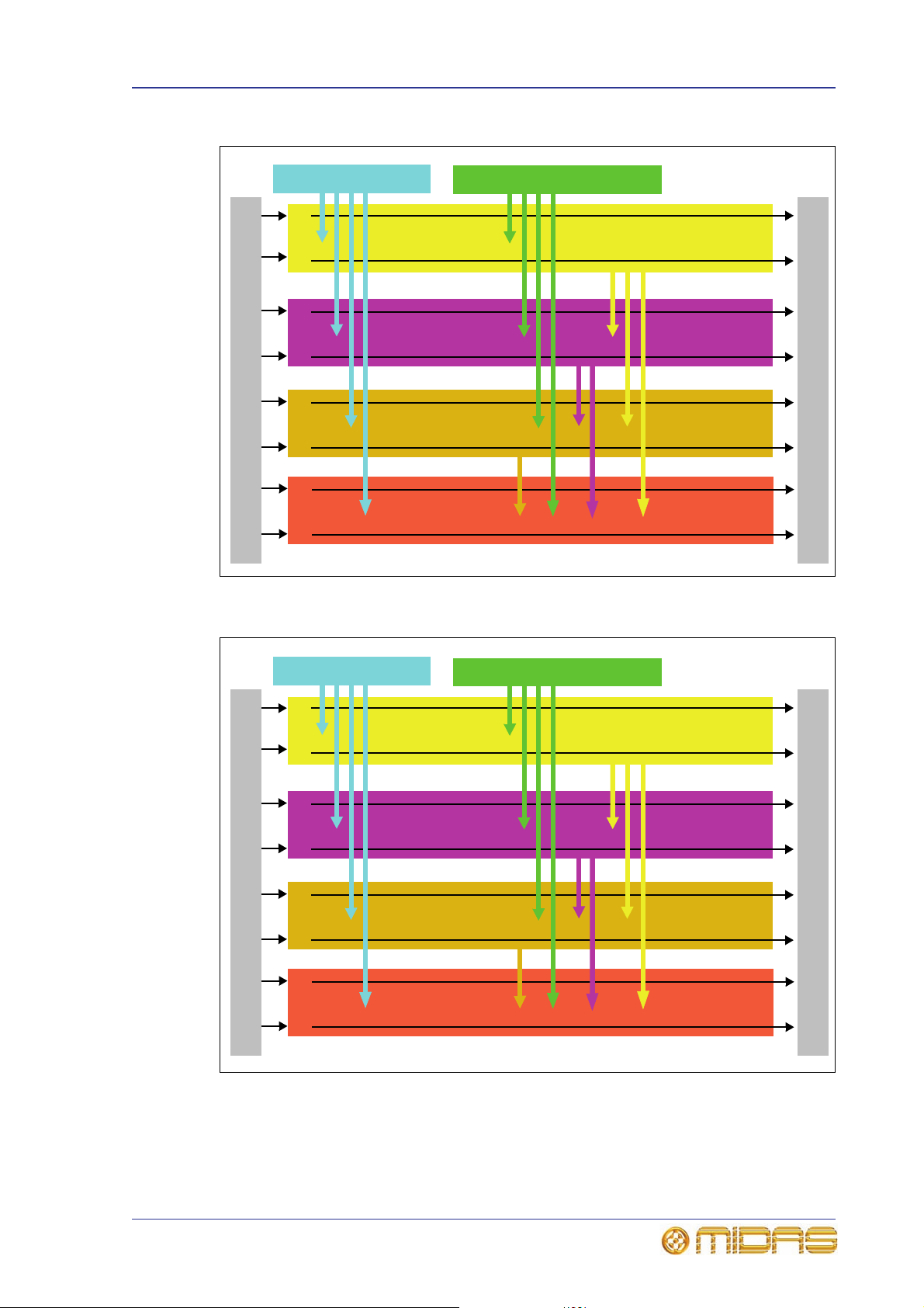
Mix matrix 19
16 aux
buses
64 in x 16 out
mix matrix
{}
80 in x 3 out
mix matrix
16 matrix
buses
83 in x 16 out
mix matrix
3 master (stereo
and mono) buses
{}
{}
56 mic/line inputs 8 mic/line return inputs
6 solo
buses
99 in x 6 out
mix matrix
{}
Bus outputs
Bus inputs
16 aux
buses
88 in x 16 out
mix matrix
{}
104 in x 3 out
mix matrix
16 matrix
buses
107 in x 16 out
mix matrix
3 master (stereo
and mono) buses
{}
{}
80 mic/line inputs 8 mic/line return inputs
6 solo
buses
123 in x 6 out
mix matrix
{}
Bus outputs
Bus inputs
Figure 2: PRO6 mix matrix
Figure 3: PRO9 mix matrix
PRO Series Live Audio Systems
Owner’s Manual

20 Chapter 2: PRO Series Live Audio Systems
Processing
Although the control centre system allows for considerable insertion of external
processing, it also embodies more than enough internal high quality processing to
eliminate the need for this, in the interests of simplicity and reduced overall system
size, weight and cost.
Processing components
The processing available is:
• Up to 80 x 12 or 24dB/oct. high pass filters.
• Up to 80 x 6 or 12dB/oct. low pass filters.
• 115 compressor/limiters with side chain filtering and multiple operating “signatures”.
• Up to 80 gates with side chain filtering.
• Up to 80 x 4-band parametric EQs with multiple shelf “modes”.
• Up to 35 x 6-band parametric EQs with hi/lo pass modes.
• 8 assignable 31-band graphic EQs.
• Up to 36 additional 31-band graphic EQs that utilise effects processor digital signal
processing (DSP), reducing the available effects quantity stated below.
• Up to 8 effects processors selectable from reverb, delay, flanger, phaser, dynamics,
compressor and pitch shifter.
Input channel processing
Each of the 80 (maximum) full-function input channels has:
• Analogue and digital gain.
• Phase reverse switch.
• Input delay.
• Swept high pass filter with choice of two filter slopes.
• Swept low pass filter with choice of two filter slopes.
• Frequency-conscious compressor with choice of four compression styles.
• Frequency-conscious noise gate with external side chain.
• Insert point.
• Treble EQ filter with choice of four filter types.
• Parametric hi-mid EQ filter.
• Parametric lo-mid EQ filter.
• Bass EQ filter with choice of four filter types.
• Routing via level controls to 32 mix buses.
• Routing via pan control to left and right master buses.
• Routing to mono master bus.
•Panpot (SIS™).
• Direct output.
Each of the eight auxiliary inputs has:
• Input gain.
• Source from internal FX or external input.
PRO Series Live Audio Systems
Owner’s Manual

Processing 21
•EQ.
•Fader.
•Panpot (SIS™).
• Routing via level controls to the matrix buses (8 or 16).
• Routing via pan control to the left, right and mono master buses.
Mix channel processing
Each of the 16 auxiliary mix buses has:
• Subgroup, auxiliary or mix minus modes.
• Dual mono or stereo pair modes.
• Six-band PEQ.
• Optional 31-band GEQ (replaces PEQ).
• Frequency-conscious compressor with choice of five compression styles.
• Insert point.
• Routing via level controls to the matrix buses (8 or 16).
• Routing via pan control to the left, right and mono master buses.
• Direct input.
Each of the matrix buses (8 or 16) has:
• Six-band PEQ.
• Optional 31-band GEQ (replaces PEQ).
• Five-mode frequency-conscious compressor with soft clip limiter and external side
chain.
• Insert point.
• Direct input.
Output channel processing
Each of the matrix buses (8 or 16) has:
• Six-band PEQ.
• Optional 31-band GEQ (replaces PEQ).
• Five-mode frequency-conscious compressor with soft clip limiter and external side
chain.
• Insert point.
• Direct input.
Each of the three master output buses has:
• Six-band PEQ.
• Optional 31-band GEQ (replaces PEQ).
• Five-mode frequency-conscious compressor with soft clip limiter and external side
chain.
• Insert point.
• Direct input.
• Routing via level controls to the matrix buses (8 or 16).
PRO Series Live Audio Systems
Owner’s Manual

22 Chapter 2: PRO Series Live Audio Systems
Effects processing and GEQs
The PRO Series contains six or eight mono Klark Teknik (KT) GEQs and seven effects
processors as standard.
The seven effects processors can be freely chosen from:
• KT DN780 reverb.
•Delay.
•Flanger.
•Phaser.
• Pitch shifter.
• SQ1 dynamics.
• Stereo 3-band compressor.
The six or eight mono KT GEQs can be patched into any output. There are many
patching options for the effects processors:
• Assign to any insert send/return.
• Assign to any pool, in or out.
• Assign FX out to aux return.
• Assign FX in to aux send (post-fade).
• Assign FX out to bus direct in.
• Assign FX in to channel direct out.
A Klark Teknik DN9331 RAPIDE motorised fader GEQ controller can be used with the
PRO Series. This unit provides rapid adjustments of the graphics with real hardware,
and not a mouse and screen. The graphic channel is selected either by the solo button
(solo tracking system (STS™)) on the PRO Series Control Centre or by buttons on the
DN9331 itself.
Audio physical connections
The maximum total number of physical analogue XLR connections possible on a PRO
Series Live Audio System is 288, plus the six local monitor outputs, talkback line out,
talk line in and talkback mic in on the rear of the control centre. The 288 configurable
connections can be any combination of inputs and outputs, in multiples of eight of each
type.
The maximum number of 288 configurable I/O can be increased up to 576 if a
combination of different types of I/O card used. The five available card types are
DL441, DL442, DL443, DL444 and DL452 (see Table 2 “Range of PRO Series equipment
supply” on page 1 4). Any three of these cards can be fitted directly into the rear of a
PRO Series Control Centre, and the remainder are fitted in the configurable I/O boxes.
All of the configurable I/O are freely routable on a scene-by-scene basis.
Surround capabilities
Theatres and broadcast have differing requirements for surround and both are catered
for in the PRO Series.
Conventional stereo and SIS™ panning is assignable on a channel-by-channel basis
(channel one can be in stereo, while channel two can be in SIS™), as follows:
• Stereo left–right routing to master buses.
• SIS™ left–right–centre routing to master buses.
PRO Series Live Audio Systems
Owner’s Manual

Network 23
Three additional surround modes operate as follows:
• Quad Left – Right – LS – RS routing to matrices 1, 2, 5 and 6.
• Surround Left – Right – Centre – Surround routing to matrices 1, 2, 3, 5 and 6.
• 5.1 surround Left – Right – Centre – Sub – LS – RS routing to matrices 1, 2, 3, 4,
5 and 6.
Network
The MidasNET network of the PRO Series utilises the physical connectivity of Ethernet
(EtherCon® connectors and Cat 5e/copper cable), but replaces its data protocol with
AES50 protocol (implemented as SuperMac) and the HyperMac high capacity system,
which are more suited to high quality, low latency audio distribution. The use of the
AES standard allows straightforward interfacing with any third party hardware that also
utilises this connection.
MidasNET connections carry digital audio, control data and standard Ethernet traffic
bi-directionally down a single cable. Cat 5e cable is used for the ‘local’ connections and
the single digital ‘snake’ (equivalent to a 384-channel analogue multi-core) between
control centre and DL371 Audio System Engine. The combination of audio, control,
clock and third party Ethernet data in a single network means that the hardware
interfaces on a single RJ45 connection.
All system connections are duplicated for full dual redundancy.
Reliability (redundancy)
All critical system connections and most components incorporate integral backup and
recovery strategies such as redeployment of resources, N+1 redundancy or dual
redundancy etc. A modular approach to software, hardware and physical construction
also aids reliability and simplifies servicing. The following lists some examples:
• The DL371 Audio System Engine incorporates N+1 redundant power supplies and
five modules, with the capability to fit an optional sixth spare module. The standard
failure recovery for modules will be redeployment of critical roles typically causing
loss of some less important inputs. With the optional sixth module fitted, the system
will operate as N+1 and there will be no loss of function after redeployment.
• The router is contained in the same rack and incorporates dual HyperMAC
connections in and out.
• The control centre contains dual redundant master controllers, dual GUI screens and
N+1 redundant power supplies.
• All I/O units incorporate dual redundant power supplies, and the DL351 and DL451
are modular in blocks of eight to limit the potential for total audio connection failure.
This resilience strategy provides high reliability performance at a reasonable cost
because it is designed in from the start and not as an afterthought.
Control software
The operating system of the PRO Series is Linux, w hich is an open-source, stable,
proven operating system (OS). Linux is used in many mission-critical applications
worldwide and has allowed Midas’ software engineers to write a ground-up system that
contains no ‘hidden’ or unused code. This has resulted in an efficient, compact
application, which is quick in operation, quick booting and comparatively easy to debug.
Two copies of the master control software run on separate processors to provide
resilience to failure.
PRO Series Live Audio Systems
Owner’s Manual

24 Chapter 2: PRO Series Live Audio Systems
GUI
The PRO Series has two, daylight-viewable, TFT screens that provide fast zone and
channel strip status indication. Although any screen can display any information, in the
standard configuration, screen information relates to module location. So, the mix bay
screen displays the channel strip and fast zone (12 inputs and 16 outputs), while the
master bay screen displays the channel strip, input fast zone (four inputs) and all
meters. The master bay screen is also generally used for automation, effects, GEQs,
third party screens etc., although this is dependent on the current application (concerts
will probably be different to theatre) and also operator preference.
The screens are controlled from the primary navigation zone at the bottom of the
master bay via two trackballs. A USB keyboard (supplied) is used for text editing.
System card expansion
Additional digital I/O format options will be available later, for example, MADI.
Console linking
You can link two PRO Series Control Centres together. Just connect an AES50 cable
from a spare AES50 port on one router to a spare port on another, and then configure
them via the “Generic AES50” connections option in the GUI menu’s Patching screen.
Integration of third party hardware/software
The PRO Series network includes the capability to interface any third party hardware
that uses AES/EBU or AES50 digital audio, or a standard analogue audio interface.
Each PRO Series AES/EBU input and output has a sample rate converter.
Synchronisation to external AES3 interfaces can be:
• Global - via inputs on the routers.
• Local to each input.
• Local to each output (synchronisation to adjacent local output).
Multiple local connections can be at different sample rates.
The use of the AES50 protocol for the transmission of digital audio means that any third
party digital audio hardware that features this connection can be connected to the
Midas network, and will transfer audio to and from the Midas hardware without any
additional interfaces or converters (provided it runs in TDM 96kHz mode). This will be
particularly useful as the protocol gains acceptance with recording and playback
devices, loudspeaker controllers, audio networking systems, digital amplifiers etc.
PC or MAC computers can use the Ethernet tunnel in the MidasNET system, and can
communicate with other computers on the network.
The PRO Series Control Centre features an external video for both screens, and the
master bay GUI screen (on the right) also has a three-way KVM switch. Control centre
views can be routed to external monitors, and external video sources can be displayed
on the control centre.
The KVM switch facilitates the control of three external computers via the screen,
trackball and keyboard of the control centre. This is hugely important and means that
third party systems can be controlled from within the PRO Series Control Centre without
having to move your head to look at screens placed off to one side. It also means that
there is no need to find somewhere to put multiple keyboards and mice. Examples are:
• Netmax (AES/EBU audio link initially and CobraNet™ when the 48kHz I/O module is
available on PRO Series).
• IRIS (for example, for RL amps).
PRO Series Live Audio Systems
Owner’s Manual

Integration of third party hardware/software 25
• Wireless mic controllers.
•Your email.
•DVD movies.
PRO Series Live Audio Systems
Owner’s Manual

26 Chapter 2: PRO Series Live Audio Systems
PRO Series Live Audio Systems
Owner’s Manual

Chapter 3: About The Control Centre
This chapter introduces you to the control centre and provides a brief hardware
description.
Overview of the control centre
The control centre has a combined control surface and GUI that provide an array of
easy-to-use controls for the precise manipulation of audio.
The control centre is of modular construction and is built on a robust Midas steel frame
chassis similar to those used for established Midas analogue products. The frame
houses three full size bays with a smaller one on the right. All of the bays are
controlled from a single processor and, collectively, provide the primary mixing needs
of the engineer.
All associated power supplies, computer motherboards, memory, graphics cards etc.
are housed within the control centre, which also contains a digital audio router box that
supports local FOH (insert) I/O connectors on the rear panel. Substantial forced
air-cooling is provided by a bulkhead and large (but slow moving) internal fans. These
produce very low noise, suitable for seated areas theatres and concert sound.
27
Typical control centre
Externally, the control centre has three main areas: control surface, GUI and rear
panel. The control surface is populated with instantly recognisable controls that are
logically distributed in major sections. The GUI, which comprises two screens at the top
of the centre bays, enhances operation by providing visual representations of the
control surface and also gives you extra functionality. The rear panel provides all of the
control centre and network connectivity, and houses the mains power sockets and
isolator switch.
Being of modular design, the overall form and shape of the control centre is similar to
Midas’ flagship XL8. The control surface is split into bays, each one containing a flat
fader tray and shallow raked control area. The centre bays also have a third area that
houses a steep-raked display screen.
Multiple hardware fault types are tolerated by the control centre without loss of audio
control due to the dual redundancy and N+1 methods incorporated in the system. This
is further helped by the modular nature of the bays and GUI independence. Either of
PRO Series Live Audio Systems
Owner’s Manual

28 Chapter 3: About The Control Centre
6
1
2
5
3
4
1 Input bay (12-channel).
2 Mix bay.
3 Master bay.
4 Input bay (4-channel).
5 Mix bay GUI screen.
6 Master bay GUI screen.
7 Talk mic and USB
connectors.
7
the GUI screens can be used to operate the whole control centre, even if none of the
control surface hardware is working. The unit offers the facility of universal input, N+1
redundant power supplies with three latching mains connectors.
Bay and GUI layout
The control centre has four discrete bays that house the following control surface
controls:
• Input bays (12-channel and 4-channel) — two input bays provide fast access to
input faders and important signal processing controls.
• Mix bay — provides access to outputs and groups, a detailed processing controller
(all channels) and navigational controls.
• Master bay — provides access to the master output mixes, monitor (A and B)
faders, automation, comms control, assignable effects control, and another set of
detailed processing and navigational controls.
Figure 4: Bay and GUI layout of a typical control centre
T wo GUI display screens at the top of the central bays pro vide extensive screen support
(standard configuration) and extra functionality for the channels and buses. For
example, when mixing or processing. They also facilitate the use of the GUI menu,
which gives you access to the many powerful features of the control centre, such as
patching, effects, GEQs, diagnostics etc.
PRO Series Live Audio Systems
Owner’s Manual

Control surface 29
A A
B
D
E
G
H
A — input fast zone: 16 input fast
strips across the 12-channel and
4-channel input bays provide the
operator’s ‘must have now’ controls.
B — channel strip and mixes:
processing areas, such as the D-zone
(dynamic), E-zone (EQ) and mix controls,
provide a more comprehensive control by
allowing detailed adjustments to a single
channel’s audio parameters.
C — channel and bus navigation
zone: sections for channel and bus
navigation and selection. For details, see
Chapter 7 “Navigation”.
D — output fast zone: 16 output fast
strips can be used for mixing and
processing aux, return, matrix and
master channels. Navigation and flip
buttons are on the right of the output fast
strips.
E — VCA and POP groups: VCA faders
and POP group sections.
F — miscellaneous: master channel
strips, A and B signal path monitoring,
communications, I-zone, surround
monitoring and mute groups.
G — primary navigation zone:
trackballs for mix and master bay GUI
screen control, and a screen access panel
(between trackballs) for direct access to
GUI menu options.
H — automation: scene store/recall
and system edit.
C
C
F
B
Control surface
The control surface is divided into areas whose function is, largely, dependent on bay
location. Each bay has assorted control elements with local feedback and/or support
from the two centrally located GUI display screens. The screens can be remoted via
external VGA connections, and third party systems can also be viewed/controlled via an
integrated KVM switch on the rear panel.
Figure 5: Main areas of the control surface
PRO Series Live Audio Systems
Owner’s Manual

30 Chapter 3: About The Control Centre
Channel strip
Banner
Inputs
Outputs
Channel type select buttons
All meters
display
Inputs and automation
summary
PRO6
PRO3
PRO9
During show time the screen functions that require fast access are controlled by control
knobs, pushbutton switches, faders etc. More complex functions that do not require
this fast access are controlled by the trackballs and navigational keys. A keyboard
integral to the flight case is used for text entry via the master bay GUI screen. An
external USB keyboard can be used to operate the mix bay GUI screen.
The choice of controls provided by each bay type are prioritised by access time
importance. Fast zone areas, which contain fast strips, give instant access to specific
functions across the bay, and channel strips give greater control of the selected fast
strip.
GUI
The GUI comprises two screens that provide a pictorial representation of the control
surface layout so that its displays are easy to follow at a glance. Not only does it reflect
what is happening on the control surface, but it also provides extra functionality via a
GUI menu. This menu provides access to all the screens that you will require to set up,
configure, manage and operate the entire control centre, all from a single drop-down
list of easy to follow options.
Figure 6: Typical Overview screen (default of the mix bay GUI screen)
Typical Meters screen with no show loaded (default of the master bay GUI screen)
PRO Series Live Audio Systems
Owner’s Manual

Front and rear panel connections 31
Mains power
and ventilation
Audio, control
and networking
I/O
(configuration dependent)
Each GUI screen has its own default display, although either is selectable via the GUI
main menu. The Overview screen displays 12 inputs and two sets of eight outputs,
and the Meters screen shows all the meters, four inputs and a summary of the
automation. Both screens have a banner at the top, which is constantly displayed, and
a channel strip down the outermost side.
The channel strips have a similar function to the ones on the control surface (see
Figure 5 on page 29), but provide extra functionality. Each displays an ‘overview’ of
the associated selected channel, which is divided into specific sections that provide
access to processing areas.
Front and rear panel connections
The control centre has connector panels on both the front and rear, and also to the left
of the mix bay GUI screen.
The connector panel to the left of the GUI has an XLR socket and two USB sockets for
connecting a talk mic and USB devices, respectively. For example, you can connect a
USB memory stick for show file backup and transfer, or a USB keyboard for text editing
on the GUI. The top USB socket is associated with the mix bay and the bottom one with
the master bay.
There are two panels at either end of the front of the control centre, under the
armrests. Each has a keyboard and phones socket. The left and right keyboard sockets
operate the mix and master bay GUI screens, respectively. The phones socket in the
left panel is for the monitor A section and the other one is for monitor B.
A connector panel on the rear of the control centre has three main sections (see below).
On the left are three mains power inlet and ventilation assemblies, with a
DC power switch above. The mid-section contains connections for the audio, network,
communications, intercoms, synchronisation, external remote devices and peripheral
devices. The section on the right is the user-configurable modular I/O section.
The modular I/O section can house up to three of any of the following I/O modules in
any combination: DL441 analogue input (mic) module; DL442 analogue output module;
DL443 analogue Jack I/O module; DL444 8 analogue mic in and 8 analogue line out
module and DL452 AES/EBU input and output module. This gives a maximum of 24
inputs and 24 outputs, if the appropriate cards are fitted.
Rear view of the control centre
For more information, see Chapter 29 "Panel Connections" on page 265.
PRO Series Live Audio Systems
Owner’s Manual

32 Chapter 3: About The Control Centre
External interfaces and peripheral devices
Various devices can be used with the PRO Series, such as:
• External USB mouse Instead of using the primary navigation zone to operate
either of the GUI screens, you can use an external USB mouse. This can be plugged
into any of the USB connectors on the PRO Series. The USB mouse behaves in the
same way as any PC mouse. For more information, see “Using an external USB
mouse” on page 244.
• External USB keyboard A USB keyboard can be used to operate either of the GUI
screens. For more information, see “Using an external USB keyboard” on page 244.
• MIDI Standard 5-pin connectors are housed in the rear panel for use as MIDI in,
out and through ports. These are fitted on the I/O units and, therefore, are available
at both the FOH and the stage locations.
• USB Host and slave USB ports are provided on all units and are, therefore,
available at the FOH and stage locations. In addition, the PRO Series provides USB
host ports (left of GUI screens) for keyboard, mouse and removable storage
(memory stick).
• External monitor The control centre has high density D-type connectors on the
rear panel of the PRO Series Control Centre that carry VGA signals for external
monitor connection. For more information, see “Using an external monitor” on
page 245.
• HELIX auto solo Provided by means of the Ethernet connections on the routers.
Solo tracking system (STS) is only available by using a Klark Teknik HELIX RapidE.
The console sends solo messages to the RapidE, which then pages to the console.
• Remote GEQ operation A Klark Teknik HELIX RapidE can be used to remotely
control the GEQs of the PRO Series Control Centre.
• Network inter-operability A port on the router is for general ‘rest of the world’
Mix buses
To help reduce latency the PRO Series has only four time zones for the primary channel
types, with the interconnecting buses being restricted to the intervening time. The time
zones and their channel associations are as follows:
• First time zone Input channels, including aux inputs set to input channel mode.
• Interval between first and second time zones Aux bus.
• Second time zone Aux Channels, including aux inputs that are set to effects
• Interval between second and third time zones Master bus.
• Third time zone Master outputs.
• Interval between third and fourth time zones Matrix bus.
• Fourth time zone Matrix outputs.
This differs from traditional analogue consoles, where it is often possible to mix four or
five times through a system, as latency is not an issue. However, this system has the
advantages of being able to route directly from inputs to matrix output — one bus to
another — and offering more flexible bus types (stereo, mono, aux, sub, mix minus
etc.).
Ethernet traffic. This port is isolated from th e PRO Series Cont rol Centre’s Ethernet
traffic by a routing table gateway mechanism within the router itself.
return mode.
In this system, all inputs are automatically time aligned, so there is no comb filtering,
which is often a problem with other digital consoles.
PRO Series Live Audio Systems
Owner’s Manual

Automation 33
For details of the bus types and their options, see Table 24 “Definition of primary
buses” on page 417.
Automation
The automation system can store and recall up to 1000 snapshot scenes. These contain
the setting values for every control on the control centre (excluding some of the
monitor section). Scene recall (and store) can be ‘scoped’ such that only the areas that
you want to recall (or store) are affected, while all other controls remain in their current
state.
The PRO Series can also recall/store operational preferences, so that its operation can
be configured to suit a particular application. For example, you can choose whether or
not to navigate screens on the ‘touch’ of controls, or as part of snapshot recall.
For theatre applications, channel settings can be recalled (across all scenes) from a
library of presets. This complexity allows a generic show to cope with differing
performers on a night-by-night basis, which is common in theatres.
Automation is powerful, but also dangerous, so the PRO Series has operator
lock/unlock. Therefore, accidental changes during control centre operation are
extremely unlikely.
MIDI and GPIO input/output are provided, as well as the ability to fire and respond to
contact closures per scene.
The ‘next’ LCD button has been positioned close to the VCA faders and has been
purposely designed so as to be distinct from other functions.
Processing elements
For details of the processing elements of the PRO Series, see “Processing” on page 20
and “PRO Series main processing functions” on page 364.
PRO Series Live Audio Systems
Owner’s Manual

34 Chapter 3: About The Control Centre
PRO Series Live Audio Systems
Owner’s Manual

Volume 1:Getting Started
PRO Series Live Audio Systems
Owner’s Manual


Chapter 4: Setting Up The System
This chapter shows you how to set up a live audio system to its default configuration.
Note: If you want to set up the system using a configuration other than the default,
please contact Midas Technical Support for details.
Initial set-up procedure
Initial system set-up basically comprises:
• Unpacking and checking the equipment — see “Unpacking the equipment” on
page 37.
• Making up a rack — see “Making up a rack” on page 37.
• Connecting up the equipment — see “Wiring instructions” on page 38.
37
• Powering the equipment — see “Powering the system” on page 42.
• Initial patching — see “Setting up the I/O rack devices” on page 92. It is
important to set up the type of snakes connected in the system.
• Configuring the rack unit(s) — see “Setting up the ID of the unit(s)” on page 44.
Unpacking the equipment
After carefully unpacking the equipment, save all packing materials, as they will prove
useful should it become necessary to transport the equipment later.
Inspect the equipment carefully for any sign of damage incurred during transportation.
It has undergone stringent quality control inspection and tests prior to packing and was
in perfect condition when it left the factory. However, if the equipment shows any signs
of damage, notify the transportation company without delay. Only you, the consignee,
may institute a claim against the carrier for damage during transportation.
Making up a rack
In the standard supply, the rack supplied with the your system is fully fitted with the
DL371 Audio System Engine unit and the I/O unit(s) appropriate for your system.
However, should you wish to re-configure the system to suit your own needs, take note
of the rack requirements as detailed in the following subsection.
Outboard equipment rack requirements
To ensure the correct installation and function of the outboard equipment, any rack has
to meet the following general requirements:
• Shock mounting (for non-installation environments) The rack must provide
adequate shock protection of the units it houses by incorporating
appropriately-designed shock protection methods. For example, a foam-suspended
rack or a frame suspended on anti-vibration mounts.
• Ventilation The PRO Series rack units have been designed such that their internal
ventilation airflow is drawn in through the front of the unit and expelled though the
rear. To facilitate this, rack design must ensure that cool air can flow freely through
the rack in the same direction, that is, in through the front of the rack and out
PRO Series Live Audio Systems
Owner’s Manual

38 Chapter 4: Setting Up The System
through the rear. Situations where the air flows in a circular direction around and
through a PRO Series unit must be prevented. Midas recommends that racks with
fully opening front and rear doors are used.
Caution!
Never combine units in the same rack that have been designed for
a ventilation air flow direction other than that designed for the
Midas units. To avoid this, we recommend that any non-Midas
units are housed separately.
• Rack mount supports Always secure the rear of the PRO Series units to the rack
via their rear rack mount support brackets. These brackets are fitted to every PRO
Series unit and are recommended for use in touring applications. The rack mount
support fixing hole centres are at a depth of approximately 395 mm from the front
panel.
Note: The rack mount support fixing hole centre depth from the front panel of the
DN9696 Recorder may be slightly different.
• Handles on rack case Y ou must ensure that there are sufficient external handles
fitted to the rack casing to enable the rack to be manoeuvred easily and safely, and
by the number of personnel suitable for the task. Also, these handles must be fit for
purpose.
• Clearance at rear of units Ensure an adequate clearance at the rear of the units
to provide sufficient free space to enable the cables to achieve their minimum bend
radius.
• Securing the cables We recommend that the cables at the rear of the units be
tidied using lacing bars and cable ties. This should provide optimum access to the
rear of the units for connecting other cables, switching the units on/off etc., and also
to give maximum visibility of the units’ LEDs for determining communication status,
link status, condition of audio etc.
Note: The above requirements also apply to any other Midas and Klark Teknik units,
such as the DL431 Mic Splitter.
Wiring instructions
Important:
The control centre and all of the DLnn1 units have Volex locking type plugs
fitted on their supplied mains cables, which plug into their mains IEC
connectors. When fitted properly the Volex plug locks into place, preventing it
working loose, or being inadvertently knocked loose or pulled out. For details
of how to fit/remove a Volex plug, see “Power” on page xvii.
Basically, to connect the system equipment together all you have to do is to connect
the control centre to the DL371 Audio System Engine using the Cat 5e or fibre optic
snake; the racks units should already be connected together when you receive them.
>> To connect the PRO Series Control Centre to the DL371 Audio System
Engine
1 At the rear of the PRO Series Control Centre, connect the fibre-optic or copper
snakes to the optical or copper connectors, respectively, in the snake X and
snake Y sections.
2 At the rear of the DL371 Audio System Engine, connect the two snakes to the
appropriate connectors (optical or copper) in the snake X and snake Y
sections.
PRO Series Live Audio Systems
Owner’s Manual

Wiring instructions 39
DL371 Audio
System Engine
(4 x AES50
expansion ports)
Rack (the DL251 and
DL371 units are
typically located in a
single 14U rack)
Maximum 100 m,
typically 0.5 m
(N+1 redundant
AES50)
Cat 5e snakes (100 m, bi-directional,
192 + 192-channel)
PRO3 Control Centre
(control surface, router, 8 x inputs, 8 x outputs, 8 x insert
Jack I/O pairs and 6 x monitor outputs)
DL251 Audio System
I/O (48 x inputs and
16 x outputs)
Mix position
Stage
3 x AES50 expansion
ports
Figure 7: Standard PRO3 system configuration
PRO Series Live Audio Systems
Owner’s Manual

40 Chapter 4: Setting Up The System
3 x AES50 expansion
ports
DL371 Audio
System Engine
(4 x AES50
expansion ports)
Rack (the DL351 and
DL371 units are
typically located in a
single 14U rack)
Maximum 100 m,
typically 0.5 m
(N+1 redundant
AES50)
Dual cable redundant HyperMAC
(fibre optic or copp er)
PRO6 Control Centre
(control surface, router, 8 x inputs, 8 x outputs, 8 x insert
Jack I/O pairs and 6 x monitor outputs)
DL351 Modular I/O
(56 x inputs and
8 x outputs)
Copper
Fibre optic
Mix position
Stage
Figure 8: Standard PRO6 system configuration
PRO Series Live Audio Systems
Owner’s Manual

Wiring instructions 41
DL371 Audio
System Engine
(4 x AES50
expansion ports)
Rack (the DL351, DL371
and DL451 units are
typically located in a
single 14U rack)
Maximum 100 m,
typically 0.5 m
(N+1 redundant
AES50)
PRO9 Control Centre
(control surface, router, 8 x inputs, 8 x outputs, 8 x insert
Jack I/O pairs and 6 x monitor outputs)
DL351 Modular I/O
(56 x inputs and
8 x outputs)
Mix position
Stage
DL451 Modular I/O
(24 x inputs)
3 x AES50 expansion
ports
Dual cable redundant HyperMAC
(fibre optic or copper)
Copper
Fibre optic
Standard PRO9 system configuration
PRO Series Live Audio Systems
Owner’s Manual

42 Chapter 4: Setting Up The System
Powering the system
The following details the recommended power up and power down procedures for the
system.
Note: If you are in any doubt as to how to switch the rack units on/off, refer to their
operator manuals.
>> To power up the system
Important Note:
DO NOT switch on the speaker sub-system until after the start-up of the
system has been completed.
After all system interconnections have been made (see “Wiring instructions” on
page 38), start up the system by doing the following:
1 Make sure that all of the system equipment is switched off, such as the control
centre, speaker sub-system, DL371 Audio System Engine unit and I/O unit(s).
2 Switch on the control centre (see “To switch on the control centre” on page 43).
3 In the master bay of the control centre, move all of the monitor and master
channel faders to the minimum position and mute all of the master channels (see
section F in Figure 5 “Main areas of the control surface” on page 29).
4 Power up the other system equipment, such as the DL371 Audio Syste m Engine
unit and I/O unit(s). This can be done in any order you like.
5 After the status indicator at the top of each GUI screen has
changed to green (shown right), switch on the speaker
sub-system.
6 Switch on the audio source and start playing the audio.
7 On the control centre, check that the audio inputs are routed to the master
channels. Then, unmute the master channels and gradually increase their faders
while listening to the sound levels from the speakers.
If there is no sound at all coming from the speakers when the faders are at maximum,
move the faders to below the 0dB level and check if the audio is muted somewhere
along the input paths and also check that the individual speakers are switched on. If
there is still no sound from the speakers, see “No audio” on page 393.
>> To power down the system
Important Note:
BEFORE switching off any of the system components, don’t forget to mute the
audio from the speakers and switch off the speaker sub-system.
1 Mute the audio from the speakers and switch off the speaker sub-system.
2 Switch off the I/O unit(s).
3 Switch off the DL371 Audio System Eng ine unit.
4 Switch off the control centre (see “To switch off the control centre” on page 43).
PRO Series Live Audio Systems
Owner’s Manual

Switching the control centre on/off 43
Mains
plug
Mains
outlet
Rear of control centre
1
2
3
Mains power on/off LED indicator
Switching the control centre on/off
Carry out the following to switch the control centre on or off in a safe manner,
observing all WARNINGS and Cautions.
>> To switch on the control centre
Caution (1)!
A minimum of two power supply modules must be supplying power
to the control centre for correct operation.
Caution (2)!
Before switching on, check that all monitor loudspeaker power
amplifiers are turned off or muted.
After connecting up the audio cables, carry out the following:
Switching on the control centre
1 Plug the three mains cables into the mains power outlets.
2 Observing Caution (1)! above, plug the Volex connectors (see “Wiring
instructions” on page 38) of the mains cables into the mains sockets on the rear
of the control centre. (The green LED next to each mains socket will illuminate if
its mains supply is on.)
3 Observing Caution (2)! above, apply power to the control centre by switching
the D.C. POWER switch on. The control centre will boot up and, when the
default GUI screens are displayed, it is ready for use.
>> To switch off the control centre
1 Make sure you have saved any shows, scenes or settings you require (see
“Saving your show files to a USB memory stick” on page 123).
2 At the GUI, choose homePreferencesShutdown System.
3 At the Shutdown ENTIRE system? prompt, click OK.
4 After the shutdown sequence has finished, switch off the D.C. POWER switch
(rear of control centre).
5 Disconnect the mains cables from the rear of the control centre.
PRO Series Live Audio Systems
Owner’s Manual

44 Chapter 4: Setting Up The System
Setting up the ID of the unit(s)
After connecting up your system, you may need to set up the ID of the unit(s) in the
rack, such as the DL351 Modular I/O, DL451 Modular I/O or DL431 Mic Splitter, as each
unit must have its own unique ID number. (This does not apply to the DL251 Audio
System I/O.)
Note: The I/O unit doesn’t have to be connected in the system for you to set up its ID,
as the procedure can be carried out offline.
>> To set up the ID of an unit
Although the programming menu of each type of I/O unit may look slightly different,
the procedure for setting up its ID is basically very similar. For full instructions on how
to set up the ID of each particular I/O unit, refer to its operator manual.
1 If necessary, switch on the I/O unit.
2 Press MENU and hold for approximately two seconds to enter the main menu.
3 If necessary, use the down arrow button to navigate to the set ID option.
4 Press SELECT to enter the set ID option.
5 If necessary, use the down arrow button to navigate to the desired ID number.
6 Press SELECT to select the ID number.
7 Press MENU repeatedly to exit the main menu. (The unit will automatically exit
programming mode after 20 seconds of inactivity, that is, if none of the
programming buttons are pressed within that time.)
PRO Series Live Audio Systems
Owner’s Manual

Volume 2:Basic Operation
Of The PRO
Series
PRO Series Live Audio Systems
Owner’s Manual


Chapter 5: Before You Start
This chapter is intended to familiarise you with the control centre by showing you how
to carry out some basic operations in order to get some audio out of it.
Note: As the operation of both input bays is principally the same, this chapter will
generally only show the operation of the 12-channel input bay. However, any
differences in operation between the 4-channel and 12-channel input bays will be
shown.
Please don’t forget that, although this system is a complex, high-tech piece of
equipment, it is very easy to use.
Principles of operation
Control centre operation is based on the concept of colours and groups rather than
‘layering’ or ‘paging’, which is the case with most digital consoles on the market today.
With so many channels available it is far easier to remember them by their
user-configured individual/group colour and name rather than their channel number.
The control surface is populated with instantly recognisable controls that are logically
distributed in major sections, so that all the controls you need to access most of the
time are always on the control surface, while the remainder are only one action away.
You can display all I/O meters, both on the control surface and the GUI, to give instant
monitoring feedback.
47
Operating modes
You can change certain aspects of control centre operation by assigning different tasks
to certain areas of the control surface. This section will explain the different ways in
which the control surface can operate.
Normal mode
During normal operation the 12-channel input bay is operated from the mix bay
controls and GUI screen, while the controls and GUI screen in the master bay operate
the 4-channel input bay. Both input bays operate in unison and are, in effect, area A.
Note: The 12-channel input bay will always be area A, no matter which operating mode
you are using.
Using the 4-channel input bay as area B
You can assign the 4-channel input bay as area B, thus making both the input bays
independent from each other. This facilitates two-man operation (see “Two-man
operation” on page 122).
PRO Series Live Audio Systems
Owner’s Manual

48 Chapter 5: Before You Start
Operating the top output fast strips from the master bay
During normal operation, both rows of output fast strips — which are always
independent from each other — are operated using the controls in the mix bay.
However, you can assign the master bay to control the top row of output strips.
>> To switch control of the output strips to the master bay
Press the right arrow (to right channel) button (see Figure 12 “Output channel
navigational controls” on page 66).
Controlling the mix buses in flip mode
Flip provides a more global approach to mix bus level control. Normally, you can only
use the level control knobs in the channel strips to adjust the signal level of the
aux/matrix mix buses going to the aux/matrix channels. However, by using flip you
have the option of controlling them from either the pan control knobs or the faders in
the input fast strips.
In flip mode the left/right arrow buttons in the upper channel select section scroll
across the input fast strips.
>> To configure the control centre for pan or fader flip
1 At the GUI, choose homePreferencesGeneral.
2 Depending on which option you require, click the option button of one of the
following in the Fader flip section. When an option is selected, it will contain a
red circle:
• “Flip to faders”.
• “Flip to Pans”.
>> To flip mixes to input pan/fader control
With an output selected on the control surface, press FLIP (see Figure 11 “Mix bus
navigational controls” on page 64). The button will illuminate to show you are in ‘flip’
mode. The currently selected mix bus in the input fast strips will change to AuxS1 and,
on the GUI, the background colour of the pans and faders will change accordingly.
Also, the LCD select buttons in the input fast strips will display the current bus mode,
for example, “MONO AUX”.
Hints and tips
• Check what is hidden On the control centre, unlike on an analogue control
surface, some of the settings and parameters will be hidden from view (stored in the
computer memory of the control centre). At various times during a mix we
recommend that you select and view unused parameters to make sure there are no
hidden surprises, for example, a reverb send left from a previous mix.
• Check the Meters screen It is a good idea to frequently monitor the Meters
screen (default display of the master bay GUI), which provides at a glance an
overview of the control centre’s status and operation. It shows all the meters and
the status condition of faders and some switches, such as solos and mutes.
However, some things will still remain hidden.
PRO Series Live Audio Systems
Owner’s Manual

Saving your work 49
Saving your work
We recommend that you save your work regularly while carrying out the procedures
included in this chapter. Not only is this good practise during normal operation, but in
this instance it may save you from losing some set-ups that could prove useful later on.
To do this, create a new show (see “To open the Automation screen” on page 112), and
then continue reading through the remainder of this section, following the instructions
carefully. Save your work at convenient points (see “To create a new scene using the
current settings” on page 115 and “To save a show or create a new one from the
current settings” on page 113).
Saving a show versus storing a scene
It is important to understand the differences between saving a show and storing a
scene.
• Storing a scene saves the current settings of the system to the show file. Scene
data is never updated unless you manually store a scene. The show file remains
unsaved in RAM.
Although the state of the control centre is copied every five seconds, it is not stored
in a scene. Instead, it is placed in the NVRAM (non-volatile random access memory)
of the control centre’s memory, which is a type of RAM that doesn't lose its data
when the power goes off. If the control centre loses power accidentally, these
settings are loaded so that audio parameters are identical, thus avoiding audio lev el
jumps. When power is lost, the showfile loaded (if any) will not
subsequently be restored, and any unsaved changes to it will be lost.
• Saving a show copies the show file onto the internal solid-state disk of the control
centre. This provides you with a ‘permanent’ copy, provided you shut down the
system properly as detailed in the following section.
Shutting down the control centre properly
When switching off the control centre, we recommend that you use the shutdown
option of the GUI menu (see “To switch off the control centre” on page 43).
By using shutdown, the cached copy of the show data, which is maintained by the
system, is automatically stored. Shutdown then uses the current showfile, NVRAM data
and cache files to restore the control centre to exactly the same state as at power
down; even to the point of loading the unsaved show and placing you at the correct
scene, with non-stored scene data at the control surface.
If you don’t use the Shutdown option the audio parameters are still restored, but the
show and show status (saved/unsaved) cannot be restored automatically. You must
manually reload the show, and any unsaved changes will be lost.
PRO Series Live Audio Systems
Owner’s Manual

50 Chapter 5: Before You Start
PRO Series Live Audio Systems
Owner’s Manual

Chapter 6: Working With The Control
Centre
This chapter is intended to familiarise you with control surface and GUI controls of the
control centre.
Although nearly all of the operations done via the control surface of the PRO Series
Control Centre can be replicated via the GUI, the emphasis in this chapter — and
throughout the manual — is on the former method. This is because, generally, control
surface operation is quicker and more intuitive than using the GUI. However, GUI
methods will be included where they are anomalous or if there is no control surface
equivalent.
The navigational controls, such as quick access buttons and scroll buttons, are
described in Chapter 7 "Navigation" on page 59, and the one s specifically for
automation can be found in “Managing the scenes” on page 114.
51
About the PRO Series controls
Although the control centre is populated with many familiar analogue-type controls
there are some that may be new to you, particularly the ones relating to navigation,
grouping and the GUI. The following table shows some of the controls that can be
found on the control surface of the PRO Series.
Type Description Example(s)
Pushbutton Generally two-state, that is, on/off or
enabled/disabled, and backlit or with an integral LCD
for status indication. In all cases, an illuminated
pushbutton on the control surface (or GUI) is
on/enabled and an extinguished one is off/disabled,
unless otherwise stated.
Control knob In general, the control knobs (rotary controls) are
touch-sensitive, their adjustment being shown on the
GUI. Some control knobs are backlit to help identify
their role and what they control.
Fader The high quality motorised faders are, similarly to the
control knobs, touch-sensitive so that their operation
can be tracked and simulated on the GUI.
PRO Series Live Audio Systems
Owner’s Manual
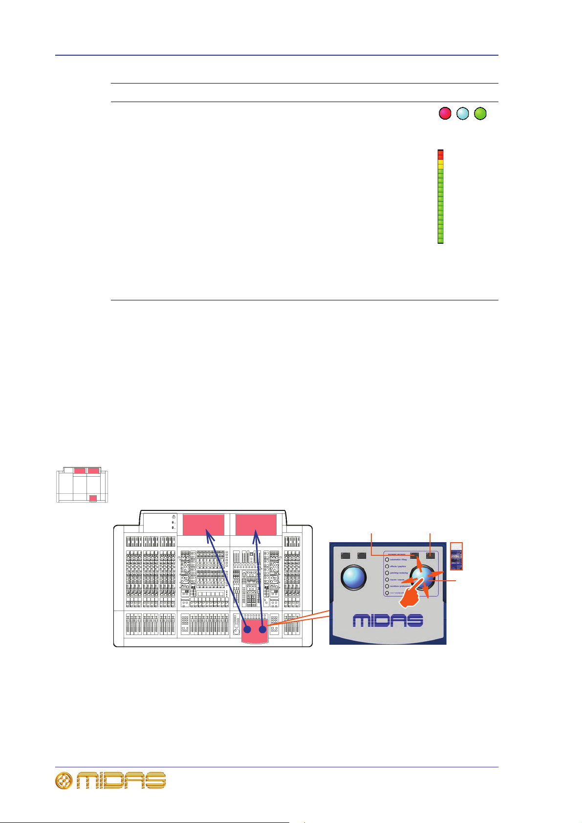
52 Chapter 6: Working With The Control Centre
Trackball
Right trackball
button
Left trackball
button
Type Description Example(s)
LED Show status indication. An illuminated LED shows an
active (on) or enabled condition and, when
extinguished, it indicates an off or disabled condition.
Meter All of the input fast strips, master fast strips and
monitors have a peak level meter. There are also
ones for the centre speaker and subwoofer of the 5.1
surround panning. In addition, each input fast strip
has a gain reduction meter for both the compressor
and gate.
Meters are included on a number of the GUI screens.
The ‘all meters’ display of the master bay’s default
GUI screen (see Figure 20, “Layout of the GUI
screens,” on page 116) provides an overview of what
is happening in the PRO Series by displaying meters
for all of the channels (inputs, outputs, monitors
etc.).
About channel operation
During normal operation the task of controlling the input (12 channels), aux, return and
matrix channels is allocated to the two bays on the left. The two bays on the right
control the input (4-channel) and master channels.
This task allocation applies similarly to the GUI screens. However, you can control any
channel from either GUI screen. This is done by navigating the channel to the GUI
channel strip via the GUI menu; control is also then available via the local channel strip
on the control surface.
About GUI operation
This section explains the basic procedures you can perform at the GUI screens. In
general, you will control and operate the GUI by combining the operations described
here.
Figure 9: Controlling the GUI
The GUI is not just an additional feature that enhances control surface operation, it is a
fully-featured tool in its own right. Not only does it show what is happening on the
control surface, but all of its controls are functional. The GUI contains most of the
controls found on the control surface and, in addition, has features that allow
configuration of the PRO Series and provide extra functionality.
PRO Series Live Audio Systems
Owner’s Manual

Common GUI screen elements 53
132456 7 8
The GUI is operated via the primary navigation zone and is principally the same as
using a laptop PC, although you can operate either screen using an external USB mouse
instead (see “Using an external USB mouse” on page 244). A USB keyboard is plugged
into the PRO Series for text editing.
Each trackball controls the movement of a pointer on its respective GUI screen (see
Figure 9). The left trackball operates the mix bay GUI screen and the right one
operates the GUI screen in the master bay. Each trackball has two buttons, which have
similar functionality to the buttons on a PC/laptop mouse. The left button is used in
click and drag operations, while the right button is generally used for editing and finer
control operations.
Click
Moving the pointer to a specific point of the GUI screen and pressing the left button is
called “clicking”. This is fundamental to GUI operation and forms the basis of many of
its operations, such as switching a button on/off, selecting list and menu items, text
editing etc. Doing the same with the right button is called “right-clicking”.
Drag
Moving the pointer to a specific point of the GUI screen and then pressing the left
button while moving the pointer up/down/left/right is called “dragging”. Dragging is
used mainly to adjust control knobs and faders, and to move sliders (attached to
drop-down lists)—although it is also used to select blocks of connectors when patching
(see “To select a block of patch connectors in the From section” on page 95). The
pointer disappears when the control has been selected to show that it is ready for
adjustment.
Common GUI screen elements
In general, you will see a banner at the top of both GUI screens that contains a number
of elements as follows:
Item Description
1 home button, opens the GUI main menu (see “GUI menu options” on
page 336).
2 Screen navigation buttons (see “To find a GUI screen that you recently
opened” on page 68).
3 Name of current screen.
4 “Not Saved” message appears when the currently selected scene/preset
library file has changes that have not been saved.
5 Title of currently selected scene.
6 status LED, indicates the health and status of the system (see
“Diagnostics” on page 393).
7 Copy and paste buttons (see “Using copy and paste” on page 118).
8 User library buttons (see “User library (presets)” on page 119).
PRO Series Live Audio Systems
Owner’s Manual

54 Chapter 6: Working With The Control Centre
Drop-down
arrow
Currently selected
list item
Scroll bar
Scroll arrow
Scroll box
Parameter values displayed on touch
You can configure the PRO Series (see “Changing the user interface
preferences” on page 250) so that the GUI displays the current
value (and dimension) of the control being adjusted.
Operating the GUI screen controls
This section shows you how to operate GUI screen elements, such as buttons, control
knobs, drop-down lists and sliders.
>> To switch a GUI button on/off
Click the button. If it has a status indicator, this will illuminate/extinguish to show that
it is on/off, respectively.
>> To adjust a GUI control knob or fader
Use a drag operation. Move the pointer up/down/left/right for adjustment.
Using drop-down lists
Certain configurable name fields, particularly the signal routing ones, have drop-down
lists that offer a number of preset or context-sensitive options to choose from. Long
lists — containing more options than can be displayed simultaneously — have sliders
that allow you to access all the options.
>> To select an option from a drop-down list
1 Click the drop-down arrow. The drop-down
list will unfold to display some or all of its
contents, depending on how many items it
contains.
2 Do one of the following:
• Click the option you require.
• If necessary, scroll the list (see “To scroll a drop-down list” below) to display
the option, and then click it.
>> To scroll a drop-down list
With the drop-down list displayed, do one
of the following:
• Drag the scroll box.
• Click the scroll bar. The scroll box will
‘jump’ in the direction of the click to
another position in the scroll bar.
• Click an up/down scroll arrow. The
scroll box will ‘jump’ in the direction of
the scroll arrow to another scroll bar
position. Clicking a scroll arrow when
the scroll box is adjacent to it has no
effect.
PRO Series Live Audio Systems
Owner’s Manual

Operating the GUI screen controls 55
Properties
window
List window
Message window
Spin buttons
Up/down spin buttons let you increase/decrease the attribute or
value of an item. For example, the amount of time a signal is
delayed (see “Input channel delay (GUI only)” on page 284 ).
About windows
There are three main types of window you
will encounter when using the GUI, as
follows (an example of each is shown in the
diagram on the right):
• Properties windows contain elements
that you can select or edit, such as
options, lists, tick boxes, text fields etc.
• Message windows contain text that can
be a prompt or an error message.
Generally, this type of window will
contain an OK and a CANCEL button by
which you can acknowledge the
message or cancel the operation,
respectively. Also, some message
windows contain a user-editable text
field, as shown in the example (right).
• List windows have a number of user-selectable options in the form of a list, and
some may also include an OK and a CANCEL button.
Similar to a window found on a PC running a Windows-based operating system,
windows can be moved around the screen, which is useful if you need to see what is
behind the window. Also, each window has a close (X) button at its upper-right corner.
>> To close a window
Do one of the following:
• If the window has an OK button, and you have made the requisite changes in the
window or you wish to acknowledge its message, click OK.
• If the window has a CLOSE button, click CLOSE. Changes made in this type of
window update the control centre ‘live’, that is, as soon as you make them, so
clicking CLOSE merely closes the window.
• If the window has a CANCEL button, and you wish to cancel any changes or abort
the operation, click CANCEL.
• Click “(X)” at the upper-right corner of the window.
>> To move a window
Use drag, first clicking on the window’s blue bar (top) and then dragging the window
where you want it.
PRO Series Live Audio Systems
Owner’s Manual

56 Chapter 6: Working With The Control Centre
GUI menu
Right arrow
shows that the
option has a
submenu
Using the GUI menu
You can open the GUI menu at either GUI screen or you can go directly a GUI menu
screen by using a screen access button.
Throughout this manual, menu/submenu option selection sequences are shown in the
following format (for example, for choosing the general preferences screen):
PreferencesGeneral
home
>> To open the GUI menu
Click home.
Opening the GUI menu
>> To select a GUI menu option
Click the menu option, for example, Monitors. The background of the menu option will
change to blue when it is ready for selection.
>> To open the submenu of a GUI menu option
Move the pointer over the arrow to the right of the desired menu option. The submenu
will open automatically to the right of the arrow.
PRO Series Live Audio Systems
Owner’s Manual

Text editing 57
>> To open a GUI menu screen using a screen access button
In the primary navigation zone, press a screen access button to open the first screen
(printed to the right of the button). Press it again to open the second screen.
These two examples show you how to use the screen access buttons to open the
Automation screen (single press) and the Graphic EQs screen (two presses). These
buttons take you directly to the screen you want.
Text editing
A keyboard is used to type in text on the GUI, for example, to configure input and
output channel names. Editable text on the GUI is contained in text boxes, which
generally consist of a single line of limited length. Although all text editing can be done
using the normal keyboard functions, the GUI can be used to assist you, for example,
by highlighting portions of text (using drag).
>> To enter/edit text via the keyboard
1 At the GUI, click in the text box to place an insertion point in it. The pointer will
change to an I-beam shape.
2 Using the keyboard, type in the new text. If the text box already contains some
text, you can delete this first or edit it, which can be done via the keyboard or by
using the cut, copy and paste options after right-clicking.
3 Press ENTER on the keyboard to exit the text box (or click on an empty area of
the GUI screen). The pointer’s shape will change back to an arrow.
PRO Series Live Audio Systems
Owner’s Manual

58 Chapter 6: Working With The Control Centre
PRO Series Live Audio Systems
Owner’s Manual

Chapter 7: Navigation
1-12 13-16 17-28 28-32 33-44 45-48 49-56
Three banks of four channels (12 channels), which
are also shown on the mix bay GUI screen
Single bank of four channels, which are also shown
on the master bay GUI screen
This chapter introduces you to navigation on the control centre and shows you how to
use its navigational tools.
For information on navigating the scenes in automation, refer to “Managing the scenes”
on page 114.
An introduction to navigation
The control centre provides you with unique navigational controls to quickly and easily
access the items, such as channels, buses, groups and processing areas, that you will
require for mixing.
Navigation is an important feature of the control centre. One of the advantages digital
consoles have over analogue ones is that their channel count is not limited by the
control surface hardware. However, this means that only a certain amount of channels
can be at the control surface at any time, while the others are ‘hidden’. So, navigation
is required to access these hidden channels whenever you need them.
59
Note: The way the control centre is set to operate may alter the function of som e of the
navigational controls. For more information, see “Operating modes” on page 47.
Navigation is primarily via the control surface, although the GUI may provide an
alternative and also has some unique navigational features of its own.
Navigating the input channels
The input channels are grouped into ‘banks’, with each bank containing four
consecutively numbered channels.
Shows the number of control centres you would need to display all of the inputs of the
PRO6 simultaneously and helps to illustrate how the inputs populate the control surface
(and GUI) in banks of four
PRO Series Live Audio Systems
Owner’s Manual
During normal operation, four banks of input channels populate the input bays, and
these are displayed across the control surface in ascending order from left to right.

60 Chapter 7: Navigation
1
2
3
4
Mix bay channel strip
Input fast
strip
7
6
8
7
9
PRO3 and
PRO6
PRO9
VCA
5
7
6
8
7
9
PRO3 and
PRO6
PRO9
10 10
12
11
Figure 10: Input channel navigational controls
Item Element(s) Description
1 Quick access
button —
channel strip
2 Quick access
button — input
fast strip
Quickly selects the local processing area of the selected
channel or channel pair, but doesn’t affect channel
selection. Illuminates (blue) when active.
Quickly selects the local input channel and assigns the
local processing area to the mix bay channel strip.
Illuminates (blue) when active.
PRO Series Live Audio Systems
Owner’s Manual
 Loading...