


MIDAS LEGEND 3000

OPERATORS MANUAL
Klark Teknik Group
Klark Teknik Building
Walter Nash Road
Kidderminster
Worcestershire
DY11 7HJ
England
Tel: +44 1562 741515
Fax: +44 1562 745371
Email:Sales@ktgplc.com
Websites:
www.midasconsoles.com
www.klarkteknik.com
MIDAS Legend 3000 Console
Operators Manual DOC02-L3000
Issue 1.2 - March 2004
Due to a policy of continual product improvement, specification
and features may be subject to change without notice.

IMPORTANT SAFETY INSTRUCTIONS
CAUTION
RISK OF ELECTRIC SHOCK
DO NOT OPEN
WARNING: TO REDUCE THE RISK OF FIRE OR ELECTRIC SHOCK,
DO NOT EXPOSE THIS APPLIANCE TO RAIN OR MOISTURE
AVIS: RISQUE DE CHOC ELECTRIQUE. NE PAS OUVRIR
These symbols are internationally accepted symbols that warn of potential hazards with
electrical products.
The lightning flash with arrowhead symbol, within an equilateral
triangle is intended to alert the user to the presence of uninsulated
“dangerous voltage” within the product's enclosure that may be of
sufficient magnitude to constitute a risk of electric shock to persons.
The exclamation point within an equilateral triangle is intended to alert
the user to the presence of important operating and maintenance
(servicing) instructions in the literature accompanying the appliance.
1. Read these instructions.
2. Keep these instructions.
3. Heed all warnings.
4. Follow all instructions.
5. Do not use this apparatus near water.
6. Clean only with a dry cloth.
7. Do not block any of the ventilation openings. Install in accordance with the manufacturers
instructions.
8. Do not install near any heat sources such as radiators, heat registers, stoves, or other apparatus
(including amplifiers) that produce heat.
9. Do not defeat the safety purpose of the polarized or grounding-type plug. A polarized plug has two
blades with one wider than the other. A grounding type plug has two blades and a third grounding
prong. The wide blade or the third prong are provided for your safety. If the provided plug does not
fit into your outlet, consult an electrician for replacement of the obsolete outlet.
10. Protect the power cord from being walked on or pinched particularly at plugs, convenience
receptacles, and the point where they exit from the apparatus.
11. Only use attachm ents / accessories specified by the manufacturer.
12. Use only with the cart, stand, tripod, bracket, or table specified by the manufacturer,
or sold with the apparatus. When a cart is used, use caution when moving the
cart/apparatus combination to avoid injury from tip-over.
13. Unplug this apparatus during lightning storms or when unused for long periods of time.
14. Refer all servicing to qualified personnel. Servicing is required when the apparatus is damaged in
any way, such as power-supply cord or plug is damaged, liquid has been spilled or objects have
fallen into the apparatus, the apparatus has been exposed to rain or moisture, does not operate
IEC-60065-Edn7-Midas

DECLARATION OF CONFORMITY
Walter Nash Road, Kidderminster, Worcestershire. DY11 7HJ. England
Tel: (44) (0) 1562 741515. Fax: (44) (0) 1562 745371
Company Registration No: 2414018
abc abc
SIGNAL PROCESSING BY DEFINITION DESIGNED FOR A PURE PERFORMANCE
We, Klark Teknik Group (UK) Plc
of, Klark Teknik Building, Walter Nash Road, Kidderminster, Worcestershire, DY11 7HJ.
Declare that a sample of the following product:-
Product Type Number Product Description Nominal Voltage (s) Current Freq
Legend 3000 Professional Audio 115V AC 5.0A 50/60Hz
Mixing Desk 230V AC 2.5A
to which this declaration refers, is in conformity with the following directives and/or standards:-
Directive(s) Test Standard(s)
Generic Standard using EN55103 Limits and Methods EN50081/2
Class B Conduct Emissions EN55103
Class B Radiated Emissions EN55103
Fast Transient Bursts EN61000-4-4
Static Discharge EN61000-4-2
Basic Electrical Safety EN60204
LVD EN60065
Harmonics EN61000-3-2
Flicker EN61000-3-3
Signed:............................
Date: 19 March 2002
th
Name: David Hoare
Authority: Technical Director, Klark Teknik Group (UK) Plc
Attention!
Where applicable, the attention of the specifier, purchaser, installer or user is drawn to special limitations of use
which must be observed when these products are taken into service to maintain compliance with the above
directives. Details of these special measures and limitations to use are available on request and are available
in product manuals.
A Subsidiary of Telex communications, Inc.


A TTENTION!
The following special limitations apply to the console and must be observed in order to maintain safety and
electromagnetic compatibility performance:
POWER CONNECTION
The console should only be operated with the power supply connected to ground via its mains supply
connector.
CONTROL CONNECTIONS
The console should only be operated with high quality screened control cables. All connector shells should be
of metal construction so that they provide a screen when they are plugged into the console. All ground
connections should be made as shown on the connections page (over leaf).
AUDIO CONNECTIONS
The console should only be operated with high quality screened twisted pair audio cables. All connector shells
should be of metal construction so that they provide a screen when they are plugged into the console. All
ground connections should be made as shown on the connections page (over leaf).
ELECTRIC FIELDS
If the console is operated in an electromagnetic field that is amplitude modulated by an audio frequency signal,
the signal to noise ratio may be degraded. Degradation of up to 60dB may be experienced under extreme
conditions (3V/m, 90% modulation).
INSTALLATION
There are a number of points to consider when installing a mixing console. Many of these points will have
been addressed before the console is even unpacked but it is worth repeating them.
POSITION
The console should be located in a convenient space commensurate with the use to which the console is being
put. Ideally a cool area is preferred not in close proximity to power distribution equipment or other potential
sources of interference. Provision should be made for some flat surface surrounding the console to prevent
people using it as a table top.
POWER
The power supply should be located as far from the console as the connecting cable will allow. It should be
set for the appropriate line voltage and plugged into the mains outlets using the supplied cables.
THE POWER SUPPLY SHOULD NEVER BE OPERATED
WITH THE MAINS EARTH DISCONNECTED
Please note that the power supply contains LETHAL VOLTAGES gr eatly in excess of the mains voltage and
that its rails can produce extremely large currents which could burn out equipment and wiring if shorted. All
testing and servicing should ONL Y be carried out by qualified engineers.

LEGEND 3000 CONNECTORS
Terminator
Consoles can be linked using the
Midas Can Bus. Depressing the
terminator defines the end of the
chain and prevents any possible
unwanted signal being sent back
up the chain.
Midas Can Bus
CAN
BUSS
Pin 1: +18V (100mA max)
Pin 2: Can low
Pin 3: OV Can
Pin 4: Can High
Pin 5: -18V(100mA max)
Input / Output XLR
Pin 1: Ground
Pin 2: Hot
Pin 3: Cold
IN
MIDI In
Pin 2: Ground
Pin 4: In+
Pin 5: In-
56 Way Edac Connector
(see page 41for wiring details)
T
H
ROU
MIDI Thru
Pin 2: Ground
Pin 4: In+
Pin 5: In-
RS-232
Pin 2: Receive Data
Pin 3: Transmit Data
Pin 5: GND
Input Send / Return
Tip: Hot
Ring: Cold
Sleeve: Ground
O
U
T
MIDI Out
Pin 2: Ground
Pin 4: In+
Pin 5: In-

CONTENTS
Midas L3001 Mono Input Module
Input Pod
FOH EQ
MON EQ
Midas L3011Mix Output
Meter Section
Talk Back Section
Mix Section
VCA Master Section
Midas L3021 Master Module
Aux Return Section
Group Section
Matrix Section
Automation Central Control Section
Assign Keys and Mode Switches
Snapshot Automation System
Monitor Section
Master Section
Automation System Control
Automation System
System Layout
Menu Overview V1.61
Lock States
Assign Functions
Assigning VCA’s to FOH Signal Path
Assigning Automutes to FOH Signal Path
Assigning VCA’s to MON Signal Path
Scene Storage
Menu Overview Continued
Sizes and Dimensions
Rear Panel Configuration
Edac Wiring Diagram
Block Diagrams
Specification and Overview
Midas L3750 Power Supply
Input Crib Sheet
Assigning Automutes to MON Signal Path
Module
Page 1
Page 2
Page 3
Page 4
Page 9
Page 10
Page 11
Page 15
Page 18
Page 19
Page 20
Page 24
Page 25
Page 27
Page 28
Page 31
Page 32
Page 33
Page 34
Page 35
Page 36
Page 37
Page 38
Page 39
Page 40
Page 41
Page 42
Page 43
Page 47
Page 51
Page 55
Page 57
Page 67
Page 71
Page 73

48V
PAD
O
+35
+25
+60
+15
gain
hi-pass
160
60
12
6
3
0
3
6
18
20
MON
treble
5k
2k
MON
1k
400
hi-mid
front
of
house
EQ
300
100
lo-mid
MON
50
20
bass
MON
1k
400
250 400
50
monitor
EQ
insert post
FOH
1
3
5
7
9
11
16k
400
10k
20k
3k
8k
1k
2k
100
200
4k
2k
0
+6
0
+6
0
+6
0
+6
0
+6
0
+6
-6
-15
-6
-15
-6
-15
-6
-15
hi-mid 2
-6
-15
lo-mid 2
-6
-15
only
PRE
PRE
PRE
PRE
PRE
PRE
c
0
+15
0
+15
0.4
0.1
2
0.4
0.1
2
0
+15
0
+15
0
+15
0
+15
0
+6
2
0
+6
4
0
+6
6
0
+6
8
0
+6
10
0
+6
12
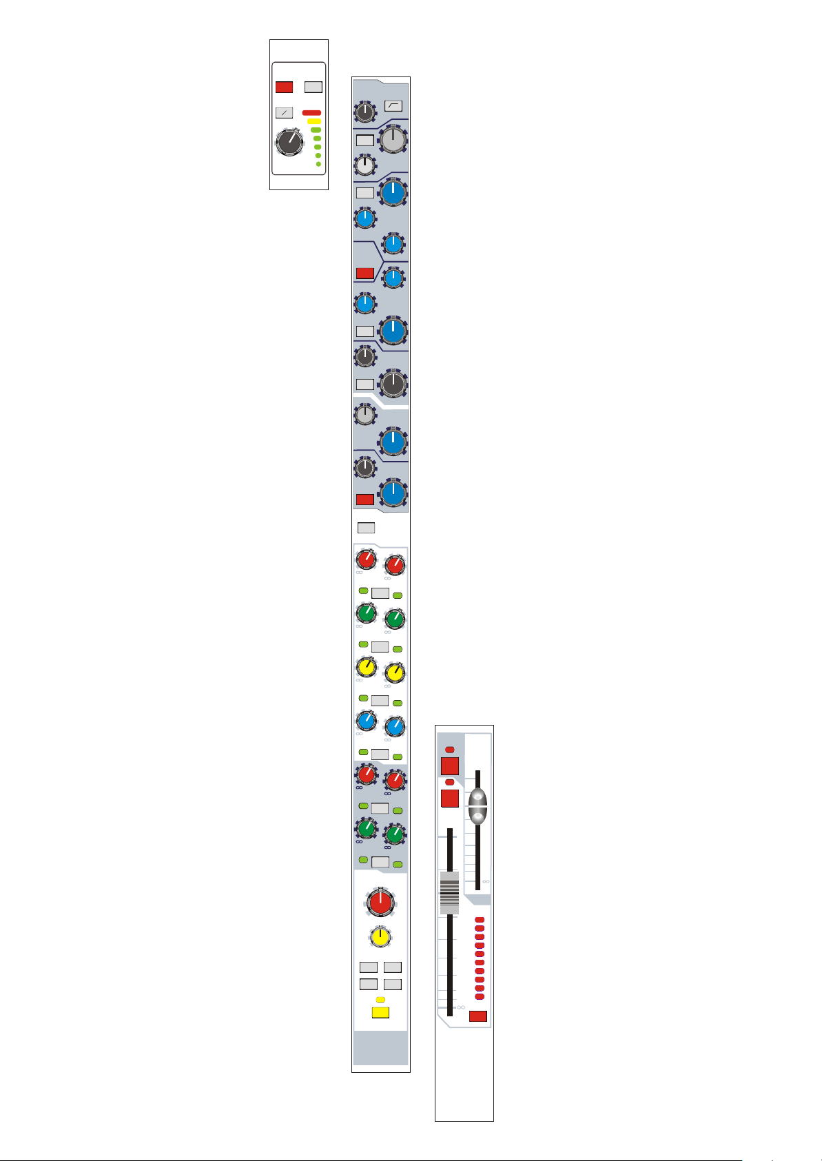
Midas L3001
Mono Input
Module
monitor
MUTE
10
MUTE
f.o.h.
5
0
5
10
10
20
30
40
5
50
dB
0
PAN
SIS
l
stereo
pan
image
SOLO
lcr
MONO
r
ST
5
1
2
3
10
4
5
15
6
7
20
8
9
30
10
40
SET
1
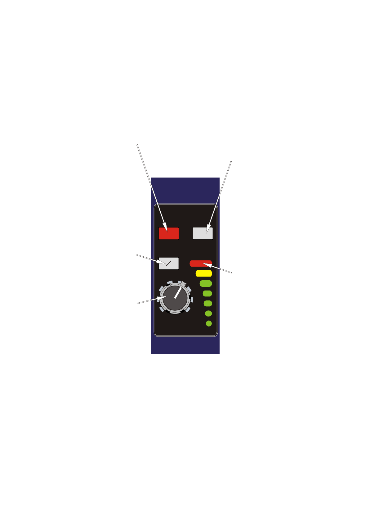
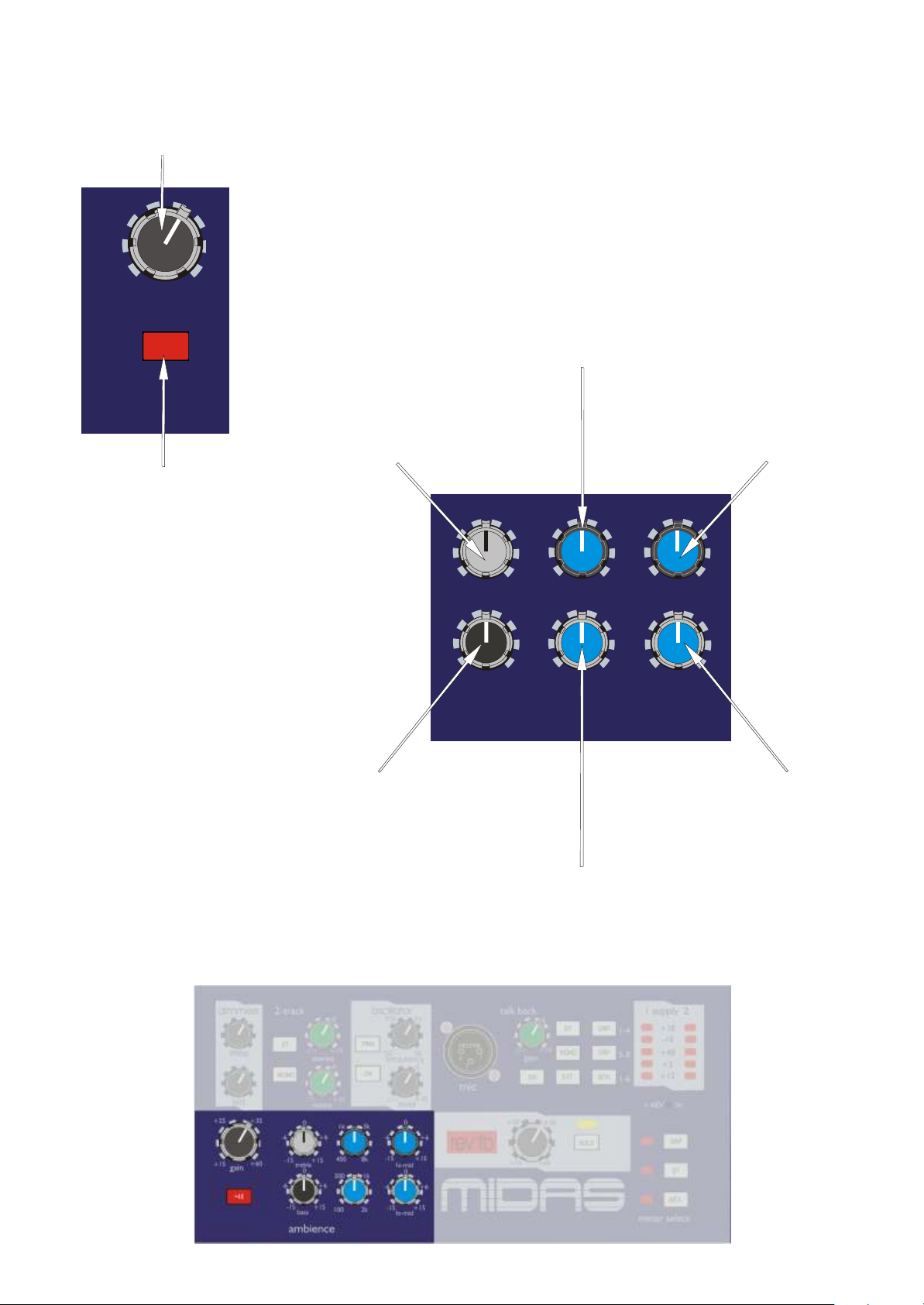
Input Pod
The 48V switch connects 48 volt
phantom power to the XLR mic input
connector. This is suitable for a
condenser microphone or DI box. A
parallel line input is also provided via a
jack which is protected from application
of 48V .
There is a global disable for the 48V on
the T alk Back section -see page12.
The PAD switch gives 30dB of
attenuation to the input signal which will
allow the connection of high output
microphones or line level signals.
Note:- Connecting a jack plug disconnects the
XLR input.
The PHASE switch activates a 180
degrees phase change within the input
amplifier.
The GAIN control gives continuous
adjustment of the input amplifier gain
from + 15dB to + 60dB.
+25
+15
-15
48V
O
gain
+35
+60
PAD
12
18
6
3
0
3
6
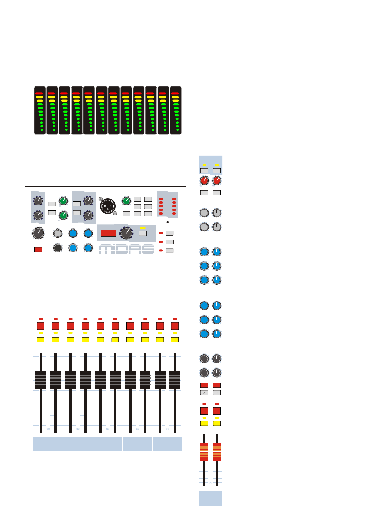
The METER monitors the peak signal
level of the main (FOH) input channel
pre fader signal path.
2
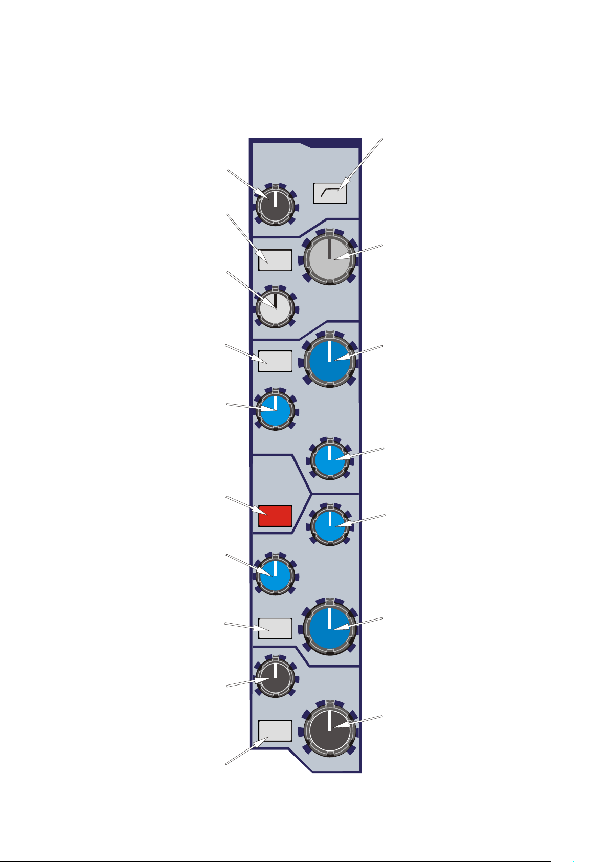
The HI PASS filter control is
continuously adjustable from 20Hz to
400Hz.
The MON switch connects the treble EQ
to operate in the monitor signal path as
well as the front of house signal path.
The treble FREQ. control gives
continuous adjustment of the frequency
range that the treble equaliser acts on
from 2KHz to 20KHz. The treble
equaliser has a shelving response.
The MON switch connects the hi mid EQ
to operate in the monitor signal path as
well as the front of house signal path.
The hi mid FREQ. control gives
continuous adjustment of the frequency
range that the hi mid equaliser acts on
from 400Hz to 8KHz.
The FOH EQ switch connects the
equaliser into the front of house signal
path.
The lo mid FREQ. control gives
continuous adjustment of the frequency
range that the lo mid equaliser acts on
from 100Hz to 2KHz.
The MON switch connects the lo mid EQ
to operate in the monitor signal path as
well as the front of house signal path.
hi-pass
60
20
MON
treble
5k
2k
MON
1k
400
hi-mid
front
of
house
EQ
300
100
lo-mid
MON
50
160
400
10k
20k
3k
8k
1k
2k
100
FOH EQ
The HI PASS switch connects the filter
in the input channel signal path before
the insert point and equaliser.
NOTE:- the signal path beyond this point is split
into two - FOH and MON.
0
-6
-15
-6
-15
-6
0.1
0.1
-15
+15
0
+15
0.4
2
0.4
2
0
+15
The TREBLE control gives continuous
adjustment of boost and cut from + 15dB
to - 15dB with a 0dB centre detent.
The HI MID control gives continuous
adjustment of boost and cut from + 15dB
to - 15dB with a 0dB centre detent.
The hi mid WIDTH control gives
continuous adjustment of bandwidth
from 0.1 to 2 octaves with a 0.4 octave
centre point.
The lo mid WIDTH control gives
continuous adjustment of bandwidth
from 0.1 to 2 octaves with a 0.4 octave
centre point.
The LO MID control gives continuous
adjustment of boost and cut from + 15dB
to - 15dB with a 0dB centre detent.
The bass FREQ. control gives
continuous adjustment of the frequency
range that the bass equaliser acts on from
20Hz to 200Hz. The bass equaliser has a
shelving response.
The MON switch connects the bass EQ
to operate in the monitor signal path as
well as the front of house signal path.
20
bass
MON
200
0
-6
The BASS control gives continuous
adjustment of boost and cut from + 15dB
to - 15dB with a 0dB centre detent.
-15
3
+15

MON EQ
The hi mid FREQ. control gives
continuous adjustment of the frequency
range that the hi mid equaliser acts on
from 400Hz to 16KHz.
The lo mid FREQ. control gives
continuous adjustment of the frequency
range that the hi mid equaliser acts on
from 50Hz to 2KHz.
The MON EQ switch connects the
equaliser into the monitor signal path
including any sections assigned to it
from the front of house EQ.
The insert defaults to be pre EQ but the
insert POST (FOH only) switch changes
the insert position to be post the front of
house EQ (i.e. it will not act upon
monitor signals).
1k
400
250 400
50
4k
16k
monitor
EQ
insert post
FOH
hi-mid 2
-6
-15
lo-mid 2
2k
-6
-15
only
0
The HI MID control gives continuous
adjustment of boost and cut from + 15dB
to - 15dB with a 0dB centre detent.
+15
0
The LO MID control gives continuous
adjustment of boost and cut from + 15dB
to - 15dB with a 0dB centre detent.
+15
4
0
0
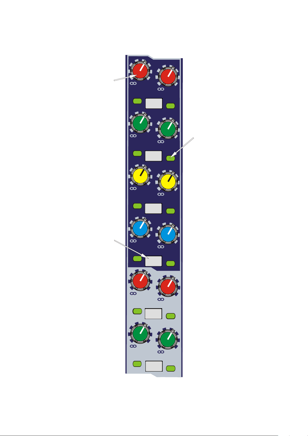
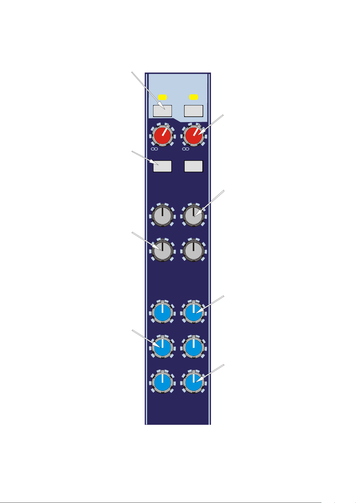
The AUX controls (1 to 12) give
continuous adjustment of the level sent
from the input channel to the aux busses.
The level adjustment is from + 6dB to
off. All aux busses can be globally
assigned to derive signals from the FOH
signal path or MON signal path. The
switch to do this is located on the mix
output module.
1
3
5
+6
+6
+6
0
0
0
PRE
PRE
PRE
2
4
6
+6
+6
+6
0
Aux send ON/OFF switching is
achieved using the console assignment
system. A routing LED below the aux
control provides indication of status,
RED being POST fader and GREEN
0
being PRE fader. The assignments may
also be stored as part of a snapshot scene.
0
The aux PRE switches change the signal
sent to the aux busses from post fader to
pre fader and this is confirmed by a led
colour change on the bus routing LEDs.
7
9
11
+6
+6
+6
0
0
PRE
PRE
PRE
+6
8
0
+6
10
0
+6
12
5
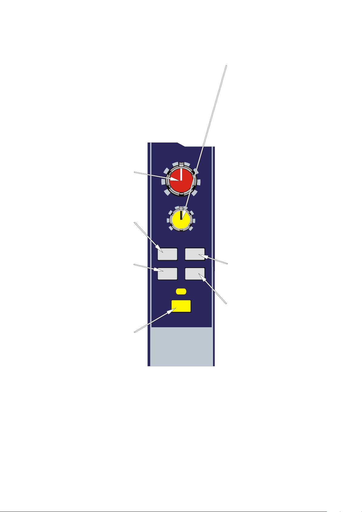
The PAN defaults to control the channel
placement within the master stereo mix
and has a constant power law. i.e. - 3dB
at the centre position.
The PAN switch changes all group bus
assignments to operate via the stereo pan
pot.
l
pan
stereo
image
When the spatial imaging system is
active the IMAGE control can modify
the action of the pan control so as to
place the channel within a three speaker
system. When the image control is fully
clockwise the pan control will operate in
full left, centre, right such that a centre
panned signal will route to the centre
speaker only and will not appear in either
of the left or right outputs. When the
image control is fully anti-clockwise the
c
pan control reverts to stereo such that a
centre panned signal will route at equal
power to the left and right speakers. All
other Image control positions generate a
composite blend of the stereo and LCR
r
panning systems so that the optimum
degree of centre image focus and speaker
power can be obtained. When the image
control and pan control are both set
central the channel will be routed with
lcr
equal power to all three speakers.
The SIS switch enables the spatial
imaging system which operates in
conjunction with the pan control to
produce a left, centre, right master mix.
The SOLO switch sends input monitor
channel signals to the MON PFL/AFL
busses and sends input front of house
channel signals to the FOH PFL/AFL
stereo busses. If the switch is pressed for
a short time it will latch on or off, but, if it
is held on for more than 1 second the
latching is disabled and when the switch
is released the channel solo will turn off.
As a default the solo system is auto
cancelling so each new solo cancels the
last. The SOLO ADD mode switch on
the master module defeats the auto
cancelling and allows multiple channel
monitoring. If the master module SOLO
SIS is enabled the front of house solo
buses will switch to LCR operation.
PAN
SIS
SOLO
MONO
ST
The MONO switch connects the post
fader channel signal to the mono master
bus.
The ST switch connects the post fader
channel signal to the master stereo bus
via the pan control.
6
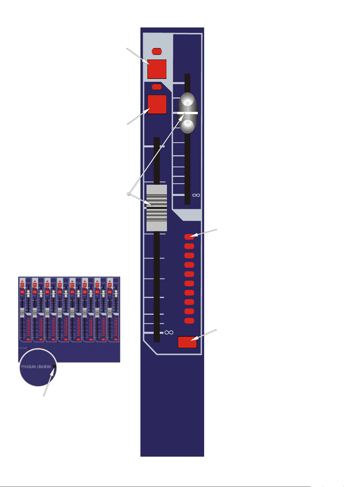
The MON MUTE switch mutes the
monitor input channel signal path at all
points after the insert send. The switch
can be controlled from snapshot
automation.
The FOH MUTE switch mutes the front
of house input channel signal path at all
points after the insert send. The switch
can be controlled from snapshot
automation.
The MON and FOH FADERS give
independent adjustment of the monitor
and front of house input channel levels
from + 10dB to off.
MUTE
MUTE
f.o.h.
10
5
0
monitor
10
5
0
5
10
20
30
40
50
dB
module disable
5
10
15
20
30
40
10
The 10 ASSIGN led's are used to show
1
2
3
4
5
6
7
8
9
the status of the VCA-FOH, VCAMON, and AUDIO group assignments.
The central controller MODE switches
toggle through the four available states
(the fourth state being AUX where status
is displayed close to the aux controls).
The SET switch is used to programme
SET
the channel AUX, VCA-FOH,
VCA_MON and AUDIO group
assignment. The central controller
MODE switches and ASSIGN keys
select the desired assignment function
and the SET switch toggles the channel
on and off with each alternate press.
The “module disable” is not intended for
normal use, however, if the automation
systems fail, this switch can be used to
stop unwanted scene updates and set the
module to a default state.
7

8
1 2
12
9
6
3
0
3
6
9
12
15
18
3 5
12
12
9
9
6
6
3
3
0
0
3
3
6
6
9
9
12
12
15
15
18
18
12
9
6
3
0
3
6
9
12
15
18
LC 311 LC 311
stereo
mono
+15
+15
oscillator
0
PINK
+10
0
ON
+10
3k
1k
+6
400
8k
1k
300
+6
100
2k
dimmers
littlite
+25
+15
gain
2-track
ST
MONO
led
+35
0
-6
-15
+60
treble
0
-6
+48
-15
bass
ambience
6 8 10
12
12
9
9
6
6
3
3
0
0
3
3
6
6
9
9
12
12
15
15
18
18
mixes
100
1k
level
NEUTRIK
5k
0
+10
0
0
1
2
3
mic
+6-6
rev tb
+6-6
50
frequency
-15 +15
hi-mid
-15 +15
lo-mid
7 9 114
12
9
6
3
0
3
6
9
12
15
18
talk back
+25
+15
12
12
9
9
6
6
3
3
0
0
3
3
6
6
9
9
12
12
15
15
18
18
0
ST GRP
+10
MONO GRP
gain
EXT
ON MTX
+35
SOLO
+60
12
9
6
3
0
3
6
9
12
15
18
1-4
5-8
1-6
1 supply 2
+48V
meter select
12
12
12
9
9
6
6
3
3
0
0
3
3
6
6
9
9
12
12
15
15
18
18
Midas L3011
Mix Output
Module
1 2
MON MON
0
0
+6
+6
ambience
TALK
5k
2k
0
-15 +15
0.4
0.1
1k
400
0
6
-15 +15
10k
20k
2
3k
8k
5k
2k
66
-15
0.1
1k
400
6
6
-15 +15
TALK
10k
20k
0
6 6
+15
0.4
2
3k
8k
0
6
+18
-18
+48
+5
+12
on
GRP
ST
MTX
MUTE MUTE MUTE MUTE MUTE MUTE MUTE MUTE MUTE MUTE
SOLO SOLO SOLO SOLO SOLO SOLO SOLO SOLO SOLO SOLO
vca 1
vca 2 vca 4 vca 6 vca 8 vca 10
vca 3 vca 5 vca 7 vca 9
10
5
0
5
10
15
20
30
40
10
5
0
5
10
15
20
30
40
10
5
0
5
10
15
20
30
40
10
5
0
5
10
15
20
30
40
10
5
0
5
10
15
20
30
40
1 vca 2 3 vca 4 5 vca 6 7 vca 8 9 vca 10
0.4
0.1
300
100
0
-15 +15
50
20
0
-15
+15
EQ EQ
O O
MUTE MUTE
SOLO SOLO
1 mix 2
2
1k
2k
100
200
0.1
300
100
66
-15 +15
66
-15
10
5
0
5
10
20
30
40
50
dB
0.4
2
1k
2k
0
66
100
50
20
200
0
66
+15
9
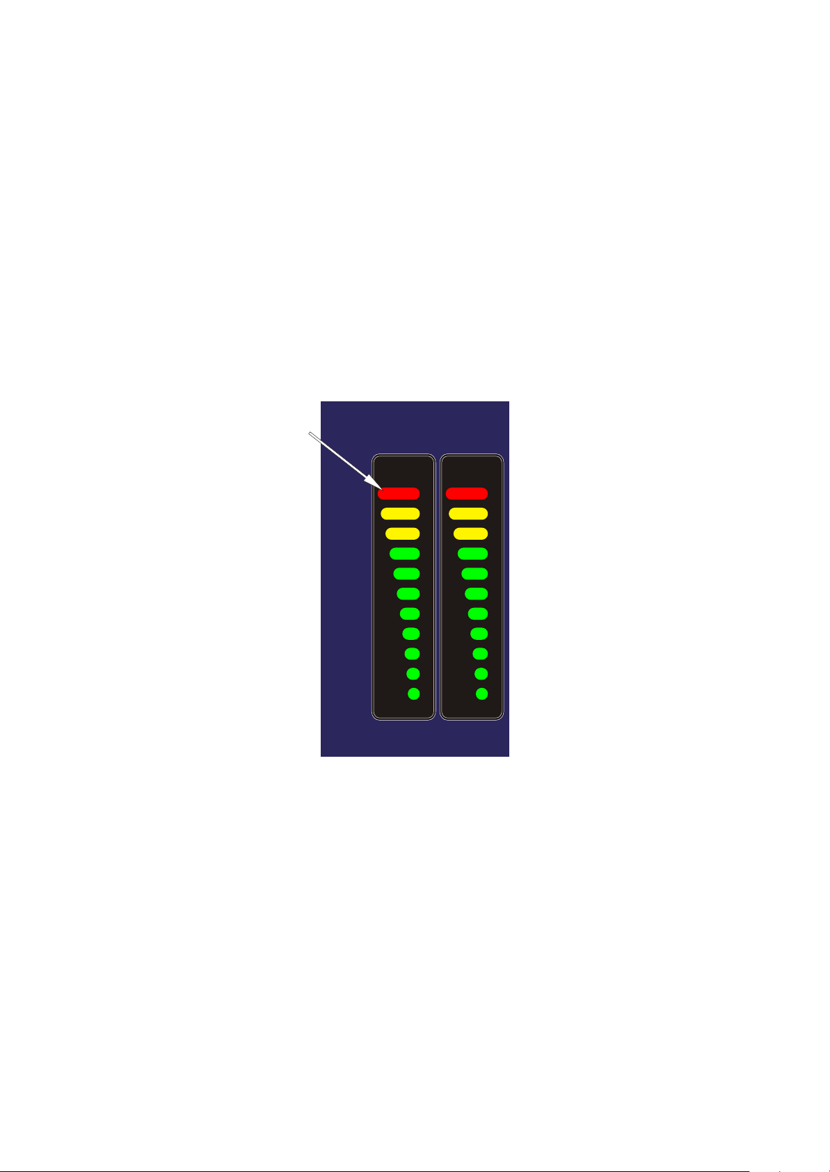
Meter Section
The METER monitors the peak signal
level of the post fader mix outputs.
1 2
18
15
12
9
6
3
0
3
6
9
12
LC 311
18
15
12
9
6
3
0
3
6
9
12
10
dimmers
littlite
led
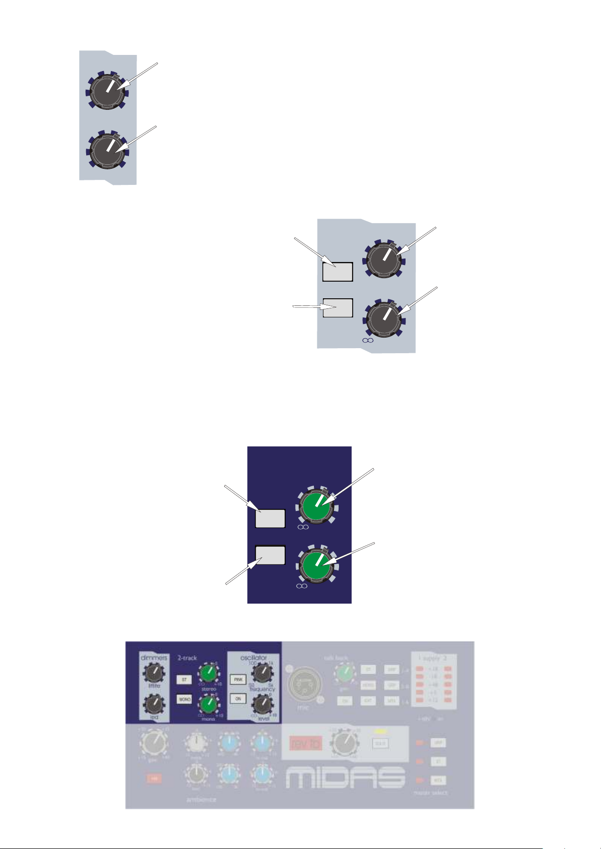
The LAMP
BRIGHTNESS control is a
dimmer for the console
littlites.
The LED BRIGHTNESS
control is a dimmer for the
console surface led's.
Talk Back Section
The PINK switch
overrides the oscillator by
giving a pink noise output.
The GENERATOR ON
switch connects the signal
generator output to the
console's internal talk
busses and to the talk
external output XLR.
The tape inputs provide a feed from an
unbalanced phono source to the stereo
and or mono master busses.
The tape to ST switch
connects the tape inputs to
the stereo master busses.
The tape to MONO switch
connects the tape inputs to
the mono master bus.
2-track
ST
MONO
stereo
mono
oscillator
PINK
ON
0
+10
0
+10
The FREQ. control gives
100
1k
continuous adjustment of
the oscillator frequency
from 50Hz to 5K.
50
frequency
5k
The generator LEVEL
0
control gives continuous
adjustment of the signal
generator peak output
level
+10
signals from +10dBu to
off.
The ST LEVEL control
provides nominal
adjustment from +10 to
off.
The MONO LEVEL
control provides nominal
adjustment from +10 to
off.
11
The TALK XLR socket
accepts balanced 150 Ohm
microphone signals. The
microphone amplifier gain
is factory set to 50dB and
operates in conjunction
with a peak limiter which
is set to +10dBu.
NEUTRIK
2
3
mic
1
talk back
gain
ON
0
+10
The talk LEVEL gives
continuous adjustment of
the post limiter signals
from +10dB to off.
The TALK MIC ON
switch connects the signal
talk mic output to the
console's internal talk
busses and to the talk
external output XLR. At
the same time it also dims
all the local monitor
outputs by 20dB to prevent
howl round.
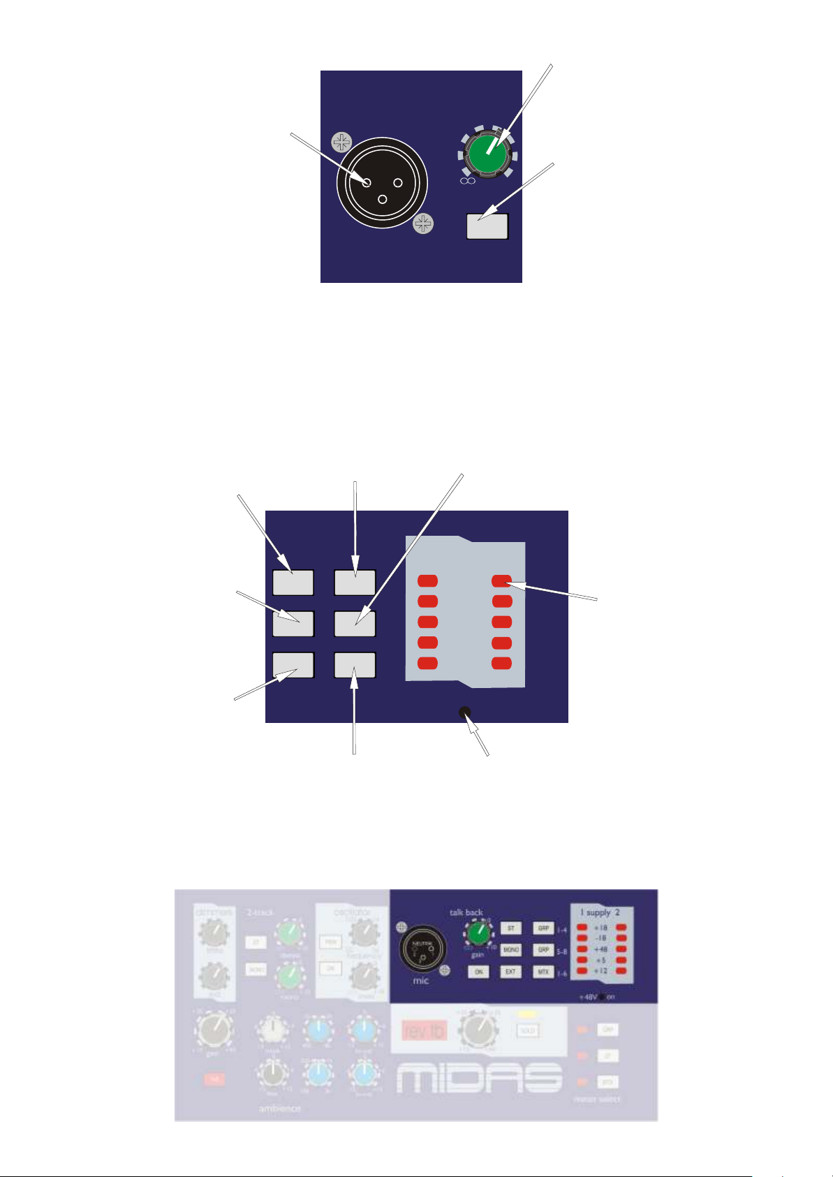
The talk to ST switch
connects the talk mic and
generator circuits to the
stereo master busses.
The talk to MONO switch
connects the talk mic and
generator circuits to the
mono master bus.
The talk to EXT switch
connects the talk mic and
generator circuits to the
external output.
The talk to GRP 1-4 switch
connects the talk mic and
generator circuits to group
1,2,3 and 4 busses.
1 supply 2
ST GRP
MONO GRP
EXT
MTX
1-4
5-8
1-6
+48V
The talk to MTX switch
connects the talk mic and
generator circuits to ALL
matrix busses.
The talk to GRP 5-8 switch
connects the talk mic and
generator circuits to group
5,6,7 and 8 busses.
+18
-18
+48
+5
+12
on
.
The POWER indicators
show the status of all rails
on both power supplies.
The 48V ON switch
activates (or safes) the
connection of 48V to the
input modules.
12
The ambience GAIN
control gives continuous
adjustment of the ambient
mic amplifier gain from +
15dB to + 60dB.
gain
+48
+35
+60
+25
+15
The 48V switch connects
48 volt phantom power to
the ambienceXLR mic
input connector.
The hi mid FREQ. control gives
continuous adjustment of the
frequency range that the hi mid
equaliser acts on from 400Hz to 8KHz.
The TREBLE control gives
continuous adjustment of the treble
equaliser boost and cut from + 15dB
to - 15dB with a 0dB centre detent.
-6
-6
-15
0
treble
0
+15
1k
+6
400
300
+6
The HI MID control gives
continuous adjustment of boost and
cut from + 15dB to - 15dB with a
0dB centre detent.
3k
8k
1k
0
+6-6
-15 +15
hi-mid
0
+6-6
-15
bass
+15
100
ambience
The BASS control gives continuous
adjustment of the bass equaliser
boost and cut from + 15dB to - 15dB
with a 0dB centre detent.
The lo mid FREQ. control gives
continuous adjustment of the
frequency range that the lo mid
equaliser acts on from 100Hz to 2KHz.
2k
-15 +15
lo-mid
The LO MID control gives
continuous adjustment of boost and
cut from + 15dB to - 15dB with a
0dB centre detent.
13
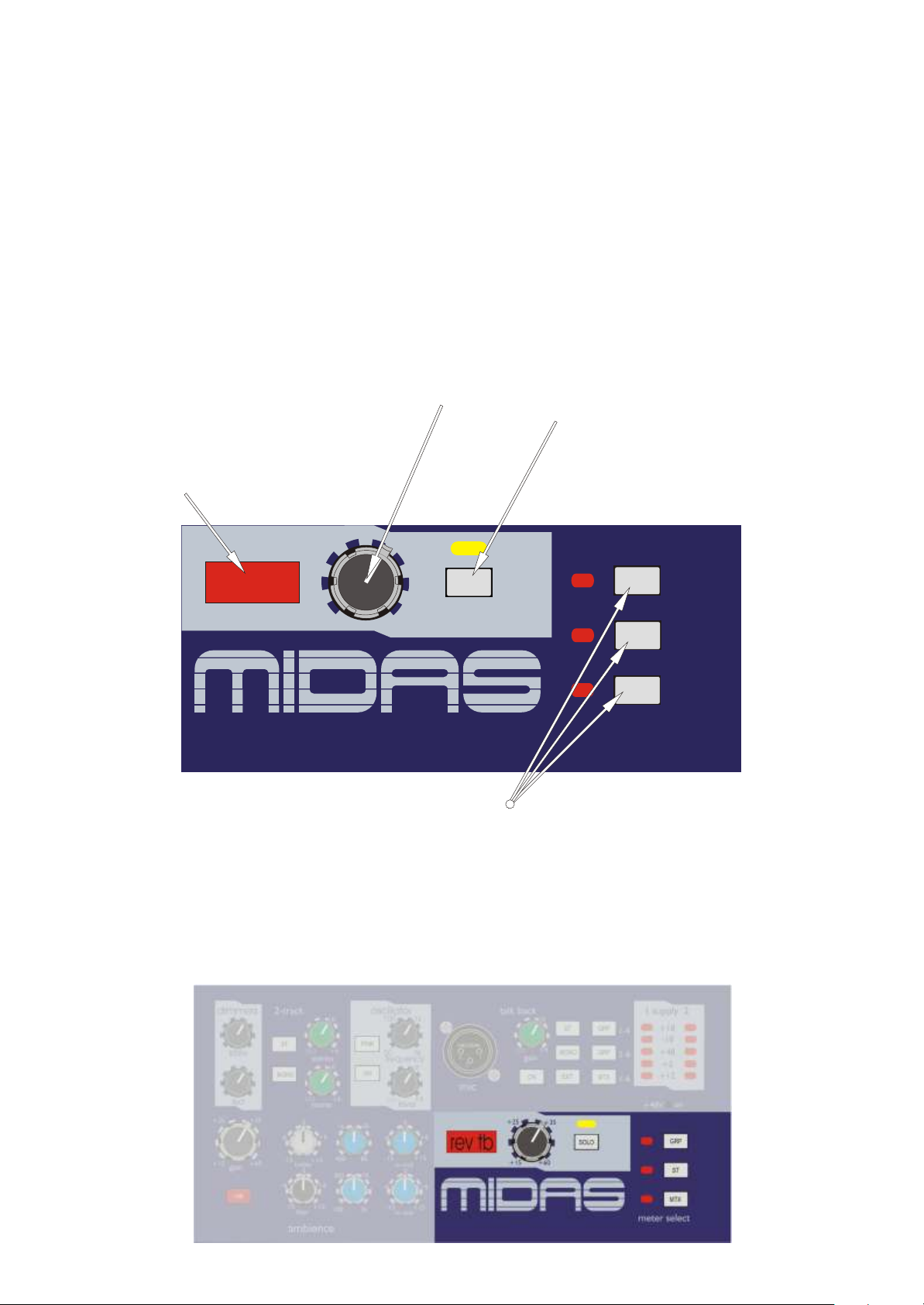
The return talk back GAIN control
gives continuous adjustment of the
talk back mic amplifier gain from +
15dB to + 60dB. 48V phantom
power is connected to this XLR
input connector.
A large led display illuminates when
signals are present on the return talk
back to prompt the operator to solo
the signal.
+25
rev tb
+15
+60
The METER SELECTOR switches
assign the master meters to monitor
Group, Stereo Return or Matrix
signals.
+35
SOLO
The return talk back SOLO switch
connects the talk signal onto the
solo busses so that it can be
monitored.
GRP
ST
MTX
meter select
14
The MON switch acts globally across a
single mix bus. It changes the input
module and stereo aux return module
sends so that they derive signal from
their monitor signal paths in place of
their front of house signal paths.
The TALK switch connects the talk mic
and generator circuits to the mix bus.
The TREBLE control gives continuous
adjustment of boost and cut from + 15dB
to - 15dB with a 0dB centre detent.
1 2
MON MON
0
+6
ambience
TALK
5k
2k
10k
20k
0
66
5k
2k
TALK
0
+6
10k
20k
Mix Section
The AMBIENCE level control provides
0
6 6
a way to mix signals from an external
microphone via an on board mic amp
onto the mix bus. The control gives
continuous adjustment from +6dB to off.
The treble FREQ. control gives
continuous adjustment of the frequency
range that the treble equaliser acts on
from 2KHz to 20KHz. The treble
equaliser has a shelving response.
The hi mid FREQ. control gives
continuous adjustment of the frequency
range that the hi mid equaliser acts on
from 400Hz to 8KHz.
-15 +15
0.4
0.1
1k
400
6
-15 +15
3k
8k
0
-15
0.1
2
1k
400
6
6
-15 +15
0.4
0
+15
3k
8k
The hi mid WIDTH control gives
continuous adjustment of bandwidth
from 0.1 to 2 octaves with a 0.4 octave
centre point.
2
The HI MID control gives continuous
adjustment of boost and cut from + 15dB
6
to - 15dB with a 0dB centre detent.
15
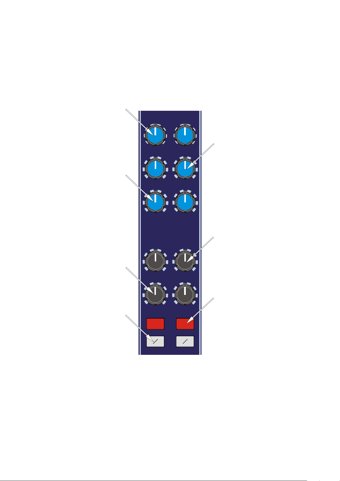
The lo mid WIDTH control gives
continuous adjustment of bandwidth
from 0.1 to 2 octaves with a 0.4 octave
centre point.
0.4
0.4
The LO MID control gives continuous
adjustment of boost and cut from + 15dB
to - 15dB with a 0dB centre detent.
The BASS control gives continuous
adjustment of boost and cut from + 15dB
to - 15dB with a 0dB centre detent.
The PHASE switch activates a 180
degrees phase change within the post
fader signal path.
0.4
300
100
-15 +15
50
20
-15
1k
0
100
200
0
+15
EQ EQ
2
0.4
300
100
2k
66
-15 +15
50
20
66
-15
0
0
2
1k
100
200
+15
The lo mid FREQ. control gives
continuous adjustment of the frequency
range that the lo mid equaliser acts on
from 100Hz to 2KHz.
2k
66
The bass FREQ. control gives
continuous adjustment of the frequency
range that the bass equaliser acts on from
20Hz to 200Hz. The bass equaliser has a
shelving response.
66
The EQ switch connects the equaliser
into the mix output signal path.
O O
16
 Loading...