


PRO2 Live Audio System
Owner’s Manual
MUSIC Group Research UK Limited,
Klark Industrial Park,
Walter Nash Road,
Kidderminster.
Worcestershire.
DY11 7HJ.
England.
Tel: +44 1562 741515
Fax: +44 1562 745371
Email: mkt.info@music-group.com
Website: www.midasconsoles.com
PRO2 Live Audio System — Owner’s Manual
DOC02-DL2 Issue A — October 2011
© 2011 MUSIC Group IP Ltd. Technical specifications and appearances are subject to change without notice and accuracy is not
guaranteed. MIDAS and KLARK TEKNIK are part of the MUSIC Group (music- group.com).
© MUSIC Group IP Limited


Owner’s Manual iii
EN
Important safety
instructions
CAUTION
ATTENTION
RISK OF ELECTRIC SHOCK!
DO NOT OPEN!
RISQUE DE CHOC ELECTRIQUE!
NE PAS OUVRIR!
Important safety instructions
Terminals marked with this
symbol carry electrical current of
sufficient magnitude to constitute
risk of electric shock. Use only
high-quality commercially-available speaker
cables with ¼" TS plugs pre-installed. All other
installation or modification should be performed
only by qualified personnel.
This symbol, wherever it appears,
alerts you to the presence of
uninsulated dangerous voltage
inside the enclosure - voltage that
may be sufficient to constitute a risk of shock.
This symbol, wherever it appears,
alerts you to important operating
and maintenance instructions in
the accompanying literature.
Please read the manual.
Caution
To reduce the risk of electric
shock, do not remove the top
cover (or the rear section). No
user serviceable parts inside. Refer servicing to
qualified personnel.
Caution
To reduce the risk of fire or
electric shock, do not expose this
appliance to rain and moisture.
The apparatus shall not be exposed to dripping or
splashing liquids and no objects filled with liquids,
such as vases, shall be placed on the apparatus.
Caution
These service instructions are for
use by qualified service personnel
only. To reduce the risk of electric
shock do not perform any servicing other than that
contained in the operation instructions. Repairs
have to be performed by qualified service
personnel.
1 Read these instructions.
2 Keep these instructions.
3 Heed all warnings.
4 Follow all instructions.
5 Do not use this apparatus near water.
6 Clean only with dry cloth.
7 Do not block any ventilation openings.
Install in accordance with the manufacturer's
instructions.
8 Do not install near any heat sources such
as radiators, heat registers, stoves, or other
apparatus (including amplifiers) that produce
heat.
9 Do not defeat the safety purpose of the
polarized or grounding-type plug. A polarized plug
has two blades with one wider than the other. A
grounding-type plug has two blades and a third
grounding prong. The wide blade or the third
prong are provided for your safety. If the provided
plug does not fit into your outlet, consult an
electrician for replacement of the obsolete outlet.
10 Protect the power cord from being
walked on or pinched particularly at plugs,
convenience receptacles, and the point where
they exit from the apparatus.
11 Use only attachments/accessories
specified by the manufacturer.
12 Use only with
the cart, stand, tripod,
bracket, or table
specified by the
manufacturer, or sold
with the apparatus.
When a cart is used,
use caution when
moving the cart/apparatus combination to avoid
injury from tip-over.
13 Unplug this apparatus during lightning
storms or when unused for long periods of time.
14 Refer all servicing to qualified service
personnel. Servicing is required when the
apparatus has been damaged in any way, such as
power supply cord or plug is damaged, liquid has
been spilled or objects have fallen into the
apparatus, the apparatus has been exposed to
rain or moisture, does not operate normally, or
has been dropped.
15 The apparatus shall be connected to a
MAINS socket outlet with a protective earthing
connection.
16 Where the MAINS plug or an appliance
coupler is used as the disconnect device, the
disconnect device shall remain readily operable.
Legal disclaimer
Technical specifications and appearances are
subject to change without notice and accuracy is
not guaranteed. MIDAS and KLARK TEKNIK are
part of the MUSIC Group (music-group .com). All
trademarks are the property of their respective
owners. MUSIC Group accepts no liability for any
loss which may be suffered by any person who
relies either wholly or in part upon any description,
photograph or statement contained herein.
Colours and specifications may vary slightly from
product. Midas products are sold through
authorized dealers only. Distributors and dealers
are not agents of MUSIC Group and have
absolutely no authority to bind MUSIC Group by
any express or implied undertaking or
representation. This manual is copyrighted. No
part of this manual may be reproduced or
transmitted in any form or by any means,
electronic or mechanical, including photocopying
and recording of any kind, for any purpose,
without the express written permission of MUSIC
Group IP Limited
ALL RIGHTS RESERVED.
© 2011 MUSIC Group IP Limited
Trident Chambers, Wickhams Cay, P.O. Box 146,
Road Town, T ortola, British Virgin Islands
Limited warranty
§ 1 Warranty
1. This limited warranty is valid only if you
purchased the product from a MUSIC Group
authorized dealer in the country of purchase. A list
of authorized dealers can be found on MUSIC
Group's website www.midasconsoles.com, or you
can contact the MUSIC Group office closest to
you.
2. MUSIC Group* warrants the mechanical and
electronic components of this product to be free of
defects in material and workmanship if used
under normal operating conditions for a period of
three (3) years from the original date of purchase
(see the Limited Warranty terms in § 4 below),
unless a longer minimum warranty period is
mandated by applicable local laws. If the product
shows any defects within the specified warranty
period and that defect is not excluded under § 4,
MUSIC Group shall, at its discretion, either
replace or repair the product using suitable new or
reconditioned product or parts. In case MUSIC
Group decides to replace the entire product, this
limited warranty shall apply to the replacement
product for the remaining initial warranty period,
i.e., three (3) years (or otherwise applicable
minimum warranty period) from the date of
purchase of the original product.
3. Upon validation of the warranty claim, the
repaired or replacement product will be returned
to the user freight prepaid by MUSIC Group.
4. Warranty claims other than those indicated
above are expressly excluded.
PLEASE RETAIN YOUR SALES RECEIPT. IT IS
YOUR PROOF OF PURCHASE COVERING
YOUR LIMITED WARRANTY. THIS LIMITED
WARRANTY IS VOID WITHOUT SUCH PROOF
OF PURCHASE.
§ 2 Online registration
Please do remember to register your new Midas
equipment right after your purchase at
www.midasconsoles.com and kindly read the
terms and conditions of our limited warranty
carefully. Registering your purchase and
equipment with us helps us process your repair
claims quicker and more efficiently. Thank you for
your cooperation!
MUSIC Group IP Limited

iv PRO2 Live Audio System
§ 3 Return materials authorization
1. To obtain warranty service, please contact
the retailer from whom the equipment was
purchased. Should your MUSIC Group dealer not
be located in your vicinity, you may contact the
MUSIC Group distributor for your country listed at
www.midasconsoles.com. If your country is not
listed please contact the “United Kingdom (Midas/
KT main office)” located under “Service
Service/Repairs” on the www.midasconsoles.com
website. Alternatively, please submit the online
warranty return form found under “Service
Warranty Registration” on
www.midasconsoles.com BEFORE returning the
product. All enquires must be accompanied by the
description of the problem and the serial number
of the product. The warranty eligibility will be
verified from the original sales receipt.
2. Subsequently, the product must be returned
in its original shipping carton, together with the
return authorization number to the address
indicated by MUSIC Group.
3. Shipments without freight prepaid will not be
accepted.
§ 4 Warranty Exclusions
1. This limited warranty does not cover
consumable parts including, but not limited to,
fuses and batteries. Where applicable, MUSIC
Group warrants the valves or meters contained in
the product to be free from defects in material and
workmanship for a period of ninety (90) days from
date of purchase.
2. This limited warranty does not cover the
product if it has been electronically or
mechanically modified in any way. If the product
needs to be modified or adapted in order to
comply with applicable technical or safety
standards on a national or local level, in any
country which is not the country for which the
product was originally developed and
manufactured, this modification/adaptation shall
not be considered a defect in materials or
workmanship. This limited warranty does not
cover any such modification/adaptation,
regardless of whether it was carried out properly
or not. Under the terms of this limited warranty,
MUSIC Group shall not be held responsible for
any cost resulting from such a modification/
adaptation.
3. This limited warranty covers only the product
hardware. It does not cover technical assistance
for hardware or software usage and it does not
cover any software products whether or not
contained in the product. Any such software is
provided "AS IS" unless expressly provided for in
any enclosed software limited warranty.
4. This limited warranty is invalid if the factoryapplied serial number has been altered or
removed from the product.
5. Free inspections and maintenance/repair
work are expressly excluded from this limited
warranty, in particular, if caused by improper
handling of the product by the user. This also
applies to defects caused by normal wear and
tear, in particular, of faders, crossfaders,
potentiometers, keys/buttons, guitar strings,
illuminants and similar parts.
6. Damage/defects caused by the following
conditions are not covered by this limited
warranty:
• improper handling, neglect or failure to
operate the unit in compliance with the
instructions given in Midas user or service
manuals;
• connection or operation of the unit in any way
that does not comply with the technical or
safety regulations applicable in the country
where the product is used;
• damage/defects caused by acts of God/
Nature (accident, fire, flood, etc) or any other
condition that is beyond the control of MUSIC
Group.
7. Any repair or opening of the unit carried out
by unauthorised personnel (user included) will
void the limited warranty.
8. If an inspection of the product by MUSIC
Group shows that the defect in question is not
covered by the limited warranty, the inspection
costs are payable by t he customer.
9. Products which do not meet the terms of this
limited warranty will be repaired exclusively at the
buyer's expense. MUSIC Group or its authorized
service centre will inform the buyer of any such
circumstance. If the buyer fails to submit a written
repair order within 6 weeks after notification,
MUSIC Group will return the unit C.O.D. with a
separate invoice for freight and packing. Such
costs will also be invoiced separately when the
buyer has sent in a written repair order.
10. Authorized MUSIC Group dealers do not sell
new products directly in online auctions.
Purchases made through an online auction are on
a "buyer beware" basis. Online auction
confirmations or sales receipts are not accepted
for warranty verification and MUSIC Group will not
repair or replace any product purchased through
an online auction.
§ 5 Warranty transferability
This limited warranty is extended exclusively to
the original buyer (customer of authorized retail
dealer) and is not transferable to anyone who may
subsequently purchase this product. No other
person (retail dealer, etc.) shall be entitled to give
any warranty promise on behalf of MUSIC Group.
§ 6 Claim for damage
Subject only to the operation of mandatory
applicable local laws, MUSIC Group shall have no
liability to the buyer under this warranty for any
consequential or indirect loss or damage of any
kind. In no event shall the liability of MUSIC Group
under this limited warranty exceed the invoiced
value of the product.
§ 7 Limitation of liability
This limited warranty is the complete and
exclusive warranty between you and MUSIC
Group. It supersedes all other written or oral
communications related to this product. MUSIC
Group provides no other warranties for this
product.
§ 8 Other warranty rights and national
law
1. This limited warranty does not exclude or limit
the buyer's statutory rights as a consumer in any
way.
2. The limited warranty regulations mentioned
herein are applicable unless they constitute an
infringement of applicable mandatory local laws.
3. This warranty does not detract from the
seller's obligations in regard to any lack of
conformity of the product and any hidden defect.
§ 9 Amendment
Warranty service conditions are subject to change
without notice. For the latest warranty terms and
conditions and additional information regarding
MUSIC Group's limited warranty, please see
complete details online at
www.midasconsoles.com.
* MUSIC Group Macao Commercial Offshore Limited of Rue de
Pequim No. 202-A, Macau Finance Centre 9/J, Macau, including
all MUSIC Group companies
MUSIC Group IP Limited

Licences
The following are the license agreements applicable to the Midas Digital Equipment.
End-User Licence Agreement for Midas™ and Klark Teknik™ Software
IMPORTANT - Please read this document carefully before using this Midas™ or
Klark Teknik™ Product. This is an agreement governing your use of software or
other machine instructions already installed on this Midas™ or Klark Teknik™
Product, as well as other software that we provide for installation on this Product.
The Midas™ or Klark Teknik™ Product will not operate in accordance with its
documentation without this software.
THIS AGREEMENT ("AGREEMENT" OR "LICENCE") STATES THE TERMS AND CONDITIONS UPON WHICH
MIDAS KLARK TEKNIK LIMITED ("COMPANY") OFFERS TO LICENSE THE INSTALLED FIRMWARE,
SOFTWARE AND/OR PROGRAMS ("the SOFTWARE") WITH THE MIDAS™ OR KLARK TEKNIK™ CONSOLE
OR SIGNAL PROCESSING PRODUCT ("PRODUCT") IN WHICH IT HAS BEEN INSTALLED BY, OR FOR
WHICH IT IS PROVIDED BY, THE COMPANY. BY USING THIS PRODUCT YOU WILL BE AGREEING TO
BECOME BOUND BY THE TERMS OF THIS LICENCE. IF YOU DO NOT AGREE TO THE TERMS OF THIS
LICENCE, DO NOT USE THIS PRODUCT AND PROMPTLY RETURN THE PRODUCT TO THE PLACE WHERE
YOU OBTAINED IT FOR A FULL REFUND. You agree to notify any persons whom you permit to operate
this Product of the terms of this Licence, and to require them to comply with these terms.
The Software is licensed, not sold, to you for use only under the terms of this Licence, and the
Company reserves all rights not expressly granted to you. The Company retains ownership of all copies
of the Software itself, and all proprietary parts of it, including those stored on or in the Product.
1. Licence: Subject to the terms and conditions of this agreement, the Company grants you, and
other persons you permit to operate the Product, a personal, limited, non-exclusive,
non-transferable licence to use the Software only on the single Product unit in which it has been
installed.
2. Restrictions: (a) The Software, and the accompanying written materials, are copyrighted and
contain trade secrets and other proprietary matter, including confidential information relating to
the specifications and performance characteristics of this Product. Save for such elements as
may be licensed to the Company, as described in paragraph 5, all rights to copyrights, trade
marks and trade secrets in the Software, or any modifications to it, are owned by the Company.
Unauthorised use or copying of the Company's proprietary Software, or any portion thereof, or
copying of those written materials, is prohibited. (b) You may not create, market, distribute, or
transfer copies of the Company's proprietary Software, or any part of it, to others, or duplicate,
rent, lease or loan that Software, or any part of it, except that you may transfer that Software
installed in this Product in conjunction with the sale, transfer, loan, rent or lease of this Product,
and subject at all times to this Licence. YOU MAY NOT REVERSE ENGINEER, DECOMPILE,
DISASSEMBLE, EXTRACT OR SEPARATE OUT, MODIFY, ADAPT, PORT, OR TRANSLATE THE
SOFTWARE, DERIVE THE SOURCE CODE OF THE SOFTWARE OR CREATE DERIVATIVE WORKS
BASED ON THE SOFTWARE OR ANY ACCOMPANYING WRITTEN MA TERIALS, save as is allowed by
licences pertaining to component parts of the Software which are licensed by third parties, as
described under paragraph 5, or otherwise by law. (c) In the event you violate any term of this
Licence, all rights granted herein will automatically and immediately terminate and you must stop
using the Software and destroy any copies of the Software.
3. Limited Warranty: Subject to your installation of any Software updates issued by the Compan y
as described herein, and the condition below, the Company warrants that the Software will
operate in compliance with the Software's material specifications and documentation for a period
of 90 days from your purchase of this Product. The Software is provided "as is" and the Company
does not warrant that the operation of the Software will meet your requirements or operate free
from error. To the greatest extent permissible by law, the Company DISCLAIMS ALL
WARRANTIES AND CONDITIONS, EITHER EXPRESS OR IMPLIED, INCLUDING THE WARRANTIES
OF MERCHANTABILITY, FITNESS FOR A PARTICULAR PURPOSE, NON-INFRINGEMENT OF THIRD
PARTY RIGHTS OR CAPABILITY OF CORRECTLY PROCESSING PROVIDING AND/OR RECEIVING

DATE INFORMATION. You understand that the Company may update or revise the Software but
in so doing incurs no obligation to furnish such updates to you. However , the Company may in its
discretion make updates available from time to time upon such terms and conditions as it shall
determine. It is a condition of the above warranty that you install any such Software updates, as
may be issued from time to time by the Company for the Software, in accordance with the
Company's instructions, and if you do not do so such warranty will cease to apply. You may view
current Software updates at http://www.klarkteknik.com and http://www.midasconsoles.com.
4. Limited Liability: THE ENTIRE RISK ARISING OUT OF YOUR USE OR PERFORMANCE OF THE
SOFTWARE REMAINS WITH YOU. THE LIABILITY OF THE COMPANY FOR ANY CLAIMS ARISING
OUT OF THIS LICENCE AND/OR BASED UPON THE SOFTWARE, REGARDLESS OF THE FORM OF
ACTION, AND INCLUDING WORK STOPPAGE, PRODUCT FAILURE OF MALFUNCTION OR ANY
OTHER COMMERCIAL LOSS OR DAMAGE, SHALL NOT EXCEED THE COST OF THE LICENCE FEE
FOR THE SOFTWARE OR THE COST OF THIS PRODUCT. SUBJECT TO THE PROVISIONS OF
APPLICABLE LAW, IN NO EVENT SHALL THE COMPANY BE LIABLE FOR ANY LO S S OF DATA, LOST
OPPORTUNITY OR PROFITS, COST OF COVER OR SPECIAL, INCIDENTAL, CONSEQUENTIAL, OR
INDIRECT DAMAGES, EVEN IF YOU ADVISE THE COMPANY OF THE POSSIBILITY OF SUCH
DAMAGES. THIS IS A FUNDAMENTAL TERM OF THIS AGREEMENT AND YOU ACKNOWLEDGE
THAT THE AMOUNT YOU PAID FOR THE SOFTWARE AND/OR THE PRODUCT REFLECTS THIS
ALLOCATION OF RISK. NOTHING IN THIS PARAGRAPH PURPORTS TO EXCLUDE OR LIMIT THE
COMPANY'S LIABILITY FOR DEATH OR PERSONAL INJURY CAUSED BY NEGLIGENCE OR ANY
OTHER LIABILITY WHICH CANNOT BE EXCLUDED OR LIMITED BY LAW.
5. Other Third-Party Computer Programs: As referred to herein, the term "Software" refers
only to proprietary Midas™ or Klark Teknik™ software, owned by the Company, that has been
provided to you for installation on, or already installed in, a Product. In addition to the Softw are,
you may have also been provided, at no additional charge, with a version of the widely-available
GNU Linux Operating System, which is a modular operating system made up of hundreds of
individual software components, each of which was written, and the copyright and other rights in
which are owned individually, by various parties (collectively, "the GNU Linux Programs"). Each
component has its own applicable end user licence agreement, and many of these agreements
permit you to copy, modify, and redistribute the applicable software, but you must review the
on-line documentation that shares a directory or otherwise accompanies each of the GNU Linux
Programs provided to you for the specific terms and conditions. Nothing in this Licence limits
your rights under, or grants you rights that supersede, the terms of any other applicable end user
licence agreement. If you wish to receive a computer-readable copy of the source code for any
of the GNU Linux Programs that have been provided with your Midas™ or Klark Teknik™ Product,
send a cheque or money order (no cash accepted), your address and [£10.00] to cover the cost
of optical media, postage and handling, to:
MUSIC Group Research UK Limited
ATTN: Linux Programs CD for Midas™/Klark Teknik™
Walter Nash Road,
Kidderminster.
Worcestershire.
DY11 7HJ.
England.
In your request, indicate your Product's name and model number, serial number and
version/release information. In your request, also indicate the relevant Software version/release
information. This offer, made pursuant to the GNU Linux Programs' end user licence agreements,
may expire according to the terms of those agreements, in which case your cheque will be
returned to you or destroyed at our option. Please note that the GNU Linux Programs that may
be available to you under this offer consists of the GNU Linux Operating System components only
and none of the proprietary application software developed by Midas or Klark Teknik is included.
Other updated Linux distributions containing application software are widely available from a
variety of Internet sources, and are often available at minimal or no cost.
6. Termination: This Licence will terminate immediately if you violate any of the Licence terms.
Upon termination you must discontinue use of the Software, and either destroy, erase or return
to Company all copies of the Software in your possession, custody or control, including those in
or on the Product.
7. General: This Licence constitutes the entire agreement between you and the Company with
respect to this Software and, save in the case of fraud, supersedes any other communication
(including advertising). Company reserves all rights not expressly granted to y ou in this licence.
If any provision of this Licence is held unenforceable, that provision shall be enforced to the
maximum extent permissible so as to give effect the intent of this Licence, and the remainder of
this Licence shall continue in full force and effect. This Licence shall be governed by English law

and the Courts of England and Wales will have exclusive jurisdiction to hear and decide any
dispute concerning it or its formation. No breach by you of any provision of this Licence shall be
waived or discharged except with the express written consent of the Company and no failure or
delay by the Company to exercise any of its rights under this Licence shall operate as a waiver
thereof and no single or partial exercise of any such right shall prevent any other or further
exercise of that or any other right. You acknowledge that the Company could be irreparably
damaged if the terms of this Licence were not specifically enforced, and agree that the Company
may seek appropriate equitable remedies with respect to breaches of this Licence, including
injunctive relief, in addition to such other remedies as the Company may otherwise have
available to it under applicable laws.
GNU General Public License (GPL)
For details of the Third Party Software License Attribution, Copyright and Terms and Conditions and
Notices, and the GNU LESSER GENERAL PUBLIC LICENSE, see the Midas Digital Equipment GNU
General Public License (GPL) Booklet part number DOC04-GPL issue A.


ix
Contents
Cover page . . . . . . . . . . . . . . . . . . . . . . . . . . . . . . . . . . . . . . . . . . . i
Licences . . . . . . . . . . . . . . . . . . . . . . . . . . . . . . . . . . . . . . . . . . . v
Contents . . . . . . . . . . . . . . . . . . . . . . . . . . . . . . . . . . . . . . . . . . ix
Overview
Chapter 1 Introduction. . . . . . . . . . . . . . . . . . . . . . . . . . . . . . . . .1
About this manual . . . . . . . . . . . . . . . . . . . . . . . . . . . . . . . . . . . . . .1
PRO2 host software version . . . . . . . . . . . . . . . . . . . . . . . . . . . . . . . .3
Service and support . . . . . . . . . . . . . . . . . . . . . . . . . . . . . . . . . . . . .3
Chapter 2 PRO2 Live Audio System . . . . . . . . . . . . . . . . . . . . . . .5
Features . . . . . . . . . . . . . . . . . . . . . . . . . . . . . . . . . . . . . . . . . . . . .5
Applications . . . . . . . . . . . . . . . . . . . . . . . . . . . . . . . . . . . . . . . . . . .6
System components (standard supply) . . . . . . . . . . . . . . . . . . . . . . . .7
Offline editor . . . . . . . . . . . . . . . . . . . . . . . . . . . . . . . . . . . . . . . . . . 7
System configurations . . . . . . . . . . . . . . . . . . . . . . . . . . . . . . . . . . . . 8
Signal flow . . . . . . . . . . . . . . . . . . . . . . . . . . . . . . . . . . . . . . . . . . . 11
Mix matrix . . . . . . . . . . . . . . . . . . . . . . . . . . . . . . . . . . . . . . . . . . . 12
Processing . . . . . . . . . . . . . . . . . . . . . . . . . . . . . . . . . . . . . . . . . . . 12
Surround capabilities . . . . . . . . . . . . . . . . . . . . . . . . . . . . . . . . . . . 14
Network . . . . . . . . . . . . . . . . . . . . . . . . . . . . . . . . . . . . . . . . . . . . 14
Resilience to failure (redundancy) . . . . . . . . . . . . . . . . . . . . . . . . . . 15
Latency management . . . . . . . . . . . . . . . . . . . . . . . . . . . . . . . . . . . 15
Operating system . . . . . . . . . . . . . . . . . . . . . . . . . . . . . . . . . . . . . . 15
GUI . . . . . . . . . . . . . . . . . . . . . . . . . . . . . . . . . . . . . . . . . . . . . . . 15
Integration of third party hardware . . . . . . . . . . . . . . . . . . . . . . . . . 15
Chapter 3 About The PRO2 Control Centre. . . . . . . . . . . . . . . . .17
Overview of the PRO2 Control Centre . . . . . . . . . . . . . . . . . . . . . . . . 17
PRO2 control surface . . . . . . . . . . . . . . . . . . . . . . . . . . . . . . . . . . . 18
Connections . . . . . . . . . . . . . . . . . . . . . . . . . . . . . . . . . . . . . . . . . . 20
Keyboard . . . . . . . . . . . . . . . . . . . . . . . . . . . . . . . . . . . . . . . . . . . . 20
External interfaces . . . . . . . . . . . . . . . . . . . . . . . . . . . . . . . . . . . . . 20
Getting Started
Chapter 4 Setting Up The System. . . . . . . . . . . . . . . . . . . . . . . .25
Initial set-up procedure . . . . . . . . . . . . . . . . . . . . . . . . . . . . . . . . . . 25
Unpacking the equipment . . . . . . . . . . . . . . . . . . . . . . . . . . . . . . . . 25
Installation . . . . . . . . . . . . . . . . . . . . . . . . . . . . . . . . . . . . . . . . . . 25
PRO2 Live Audio System
Owner’s Manual

x
Making up a rack . . . . . . . . . . . . . . . . . . . . . . . . . . . . . . . . . . . . . . .27
Connecting up . . . . . . . . . . . . . . . . . . . . . . . . . . . . . . . . . . . . . . . .28
Powering the PRO2 system . . . . . . . . . . . . . . . . . . . . . . . . . . . . . . . .30
Switching the PRO2 Control Centre on/off . . . . . . . . . . . . . . . . . . . . .31
Basic Operation Of The PRO2
Chapter 5 Before You Start . . . . . . . . . . . . . . . . . . . . . . . . . . . . 35
Principles of operation . . . . . . . . . . . . . . . . . . . . . . . . . . . . . . . . . . .35
Hints and tips . . . . . . . . . . . . . . . . . . . . . . . . . . . . . . . . . . . . . . . . .35
Saving your work . . . . . . . . . . . . . . . . . . . . . . . . . . . . . . . . . . . . . .35
Chapter 6 Working With The PRO2 Control Centre . . . . . . . . . . 37
About the PRO2 controls . . . . . . . . . . . . . . . . . . . . . . . . . . . . . . . . .37
About GUI operation . . . . . . . . . . . . . . . . . . . . . . . . . . . . . . . . . . . .38
GUI screen layout . . . . . . . . . . . . . . . . . . . . . . . . . . . . . . . . . . . . . .38
Parameter values displayed on touch . . . . . . . . . . . . . . . . . . . . . . . . .40
Operating the GUI screen controls . . . . . . . . . . . . . . . . . . . . . . . . . . .40
Using the GUI menu . . . . . . . . . . . . . . . . . . . . . . . . . . . . . . . . . . . .42
Text editing . . . . . . . . . . . . . . . . . . . . . . . . . . . . . . . . . . . . . . . . . .42
Chapter 7 Navigation . . . . . . . . . . . . . . . . . . . . . . . . . . . . . . . . . 43
An introduction to PRO2 navigation . . . . . . . . . . . . . . . . . . . . . . . . . .43
Channel navigation . . . . . . . . . . . . . . . . . . . . . . . . . . . . . . . . . . . . .43
Advanced channel navigation . . . . . . . . . . . . . . . . . . . . . . . . . . . . . .44
About GUI navigation . . . . . . . . . . . . . . . . . . . . . . . . . . . . . . . . . . .46
Chapter 8 Patching . . . . . . . . . . . . . . . . . . . . . . . . . . . . . . . . . . 47
Introduction . . . . . . . . . . . . . . . . . . . . . . . . . . . . . . . . . . . . . . . . . .47
Terms used in PRO2 patching . . . . . . . . . . . . . . . . . . . . . . . . . . . . . .47
About the Patching screen . . . . . . . . . . . . . . . . . . . . . . . . . . . . . . . .47
Patching tooltips . . . . . . . . . . . . . . . . . . . . . . . . . . . . . . . . . . . . . . .59
About the patching procedure . . . . . . . . . . . . . . . . . . . . . . . . . . . . . .60
Configuring the devices . . . . . . . . . . . . . . . . . . . . . . . . . . . . . . . . . .60
Setting up the I/O rack device(s) . . . . . . . . . . . . . . . . . . . . . . . . . . .62
How to patch . . . . . . . . . . . . . . . . . . . . . . . . . . . . . . . . . . . . . . . . .64
Chapter 9 Basic Operation . . . . . . . . . . . . . . . . . . . . . . . . . . . . . 69
Setting a mic amplifier’s input gain . . . . . . . . . . . . . . . . . . . . . . . . . .69
Setting the high and low pass filters . . . . . . . . . . . . . . . . . . . . . . . . .70
Input equalisation (E zone) . . . . . . . . . . . . . . . . . . . . . . . . . . . . . . .71
Input dynamics processing (D zone) . . . . . . . . . . . . . . . . . . . . . . . . .72
Output processing . . . . . . . . . . . . . . . . . . . . . . . . . . . . . . . . . . . . . .73
Using VCA/POPulation groups . . . . . . . . . . . . . . . . . . . . . . . . . . . . . .74
Setting up a mix . . . . . . . . . . . . . . . . . . . . . . . . . . . . . . . . . . . . . . .76
Setting up the effects rack . . . . . . . . . . . . . . . . . . . . . . . . . . . . . . . .79
Simple routing to master stereo outputs . . . . . . . . . . . . . . . . . . . . . .81
Automation . . . . . . . . . . . . . . . . . . . . . . . . . . . . . . . . . . . . . . . . . .82
Configuring the inputs and outputs . . . . . . . . . . . . . . . . . . . . . . . . . .86
Using copy and paste . . . . . . . . . . . . . . . . . . . . . . . . . . . . . . . . . . . .87
User library (presets) . . . . . . . . . . . . . . . . . . . . . . . . . . . . . . . . . . . .88
PRO2 Live Audio System
Owner’s Manual

xi
Surround panning . . . . . . . . . . . . . . . . . . . . . . . . . . . . . . . . . . . . . . 89
Area B operation . . . . . . . . . . . . . . . . . . . . . . . . . . . . . . . . . . . . . . 90
Saving your show files to a USB memory stick . . . . . . . . . . . . . . . . . . 91
External AES50 synchronisation . . . . . . . . . . . . . . . . . . . . . . . . . . . . 92
Security (locking mode) . . . . . . . . . . . . . . . . . . . . . . . . . . . . . . . . . 92
Advanced Operation And Features
Chapter 10 Stereo Linking . . . . . . . . . . . . . . . . . . . . . . . . . . . . . .95
Changing the linking options . . . . . . . . . . . . . . . . . . . . . . . . . . . . . . 96
Chapter 11 Panning . . . . . . . . . . . . . . . . . . . . . . . . . . . . . . . . . . .97
Stereo panning . . . . . . . . . . . . . . . . . . . . . . . . . . . . . . . . . . . . . . . 97
SIS™ (LCR) mode . . . . . . . . . . . . . . . . . . . . . . . . . . . . . . . . . . . . . 98
Surround panning . . . . . . . . . . . . . . . . . . . . . . . . . . . . . . . . . . . . . 100
Speaker placement . . . . . . . . . . . . . . . . . . . . . . . . . . . . . . . . . . . . 101
Chapter 12 Soloing . . . . . . . . . . . . . . . . . . . . . . . . . . . . . . . . . . .103
Solo A . . . . . . . . . . . . . . . . . . . . . . . . . . . . . . . . . . . . . . . . . . . . . 103
Solo B . . . . . . . . . . . . . . . . . . . . . . . . . . . . . . . . . . . . . . . . . . . . . 104
Solo hierarchy . . . . . . . . . . . . . . . . . . . . . . . . . . . . . . . . . . . . . . . 105
Solo in place (SIP) . . . . . . . . . . . . . . . . . . . . . . . . . . . . . . . . . . . . 105
Solo modes . . . . . . . . . . . . . . . . . . . . . . . . . . . . . . . . . . . . . . . . . 105
Chapter 13 Muting . . . . . . . . . . . . . . . . . . . . . . . . . . . . . . . . . . .107
Chapter 14 Monitors And Communications . . . . . . . . . . . . . . . .109
Monitors (A and B) . . . . . . . . . . . . . . . . . . . . . . . . . . . . . . . . . . . . 109
Solo system . . . . . . . . . . . . . . . . . . . . . . . . . . . . . . . . . . . . . . . . . 112
Signal generator . . . . . . . . . . . . . . . . . . . . . . . . . . . . . . . . . . . . . . 116
Talk osc/routing . . . . . . . . . . . . . . . . . . . . . . . . . . . . . . . . . . . . . . 117
Talk mic . . . . . . . . . . . . . . . . . . . . . . . . . . . . . . . . . . . . . . . . . . . 118
Chapter 15 Graphic Equaliser (GEQ) . . . . . . . . . . . . . . . . . . . . .121
Overview of the GEQs . . . . . . . . . . . . . . . . . . . . . . . . . . . . . . . . . . 121
About the Graphic EQs screen . . . . . . . . . . . . . . . . . . . . . . . . . . . . 121
About the GEQ window . . . . . . . . . . . . . . . . . . . . . . . . . . . . . . . . . 123
GEQ front panel features . . . . . . . . . . . . . . . . . . . . . . . . . . . . . . . . 124
Configuring the number of GEQs (and effects) . . . . . . . . . . . . . . . . . 125
Copying settings between GEQs . . . . . . . . . . . . . . . . . . . . . . . . . . . 126
Chapter 16 Internal Effects . . . . . . . . . . . . . . . . . . . . . . . . . . . .127
Overview of the internal effects . . . . . . . . . . . . . . . . . . . . . . . . . . . 127
About the effect window . . . . . . . . . . . . . . . . . . . . . . . . . . . . . . . . 128
Working with the effects . . . . . . . . . . . . . . . . . . . . . . . . . . . . . . . . 129
Effect programs . . . . . . . . . . . . . . . . . . . . . . . . . . . . . . . . . . . . . . 129
Delay effect . . . . . . . . . . . . . . . . . . . . . . . . . . . . . . . . . . . . . . . . . 130
Virtual DN780 Reverb effect . . . . . . . . . . . . . . . . . . . . . . . . . . . . . 132
Flanger effect . . . . . . . . . . . . . . . . . . . . . . . . . . . . . . . . . . . . . . . . 134
Phaser effect . . . . . . . . . . . . . . . . . . . . . . . . . . . . . . . . . . . . . . . . 135
Pitch Shifter effect . . . . . . . . . . . . . . . . . . . . . . . . . . . . . . . . . . . . 137
PRO2 Live Audio System
Owner’s Manual

xii
SQ1 Dynamics effect . . . . . . . . . . . . . . . . . . . . . . . . . . . . . . . . . . .138
3-Band Compressor effect . . . . . . . . . . . . . . . . . . . . . . . . . . . . . . .139
Dynamic EQ . . . . . . . . . . . . . . . . . . . . . . . . . . . . . . . . . . . . . . . . .140
Chapter 17 Control Groups . . . . . . . . . . . . . . . . . . . . . . . . . . . . 143
VCA and POPulation groups . . . . . . . . . . . . . . . . . . . . . . . . . . . . . .143
MCA groups . . . . . . . . . . . . . . . . . . . . . . . . . . . . . . . . . . . . . . . . .146
Auto-mute (mute) groups . . . . . . . . . . . . . . . . . . . . . . . . . . . . . . .147
About the control group screens . . . . . . . . . . . . . . . . . . . . . . . . . . .148
Configuring the groups . . . . . . . . . . . . . . . . . . . . . . . . . . . . . . . . .150
Chapter 18 Copy And Paste . . . . . . . . . . . . . . . . . . . . . . . . . . . . 151
Copying through channels/scenes . . . . . . . . . . . . . . . . . . . . . . . . . .151
Chapter 19 Assignable Controls. . . . . . . . . . . . . . . . . . . . . . . . . 153
Operating the channel fader assignments . . . . . . . . . . . . . . . . . . . . .154
Controlling a rotary control . . . . . . . . . . . . . . . . . . . . . . . . . . . . . . .155
Controlling an internal effect/GEQ . . . . . . . . . . . . . . . . . . . . . . . . . .157
Controlling a GEQ . . . . . . . . . . . . . . . . . . . . . . . . . . . . . . . . . . . . .159
Chapter 20 Scenes And Shows (Automation) . . . . . . . . . . . . . . 161
About automation . . . . . . . . . . . . . . . . . . . . . . . . . . . . . . . . . . . . .161
Automation controls . . . . . . . . . . . . . . . . . . . . . . . . . . . . . . . . . . .162
Automation screen . . . . . . . . . . . . . . . . . . . . . . . . . . . . . . . . . . . .163
Using the right-click menu . . . . . . . . . . . . . . . . . . . . . . . . . . . . . . .163
Scenes . . . . . . . . . . . . . . . . . . . . . . . . . . . . . . . . . . . . . . . . . . . . .164
Scene contents . . . . . . . . . . . . . . . . . . . . . . . . . . . . . . . . . . . . . . .165
Point scenes . . . . . . . . . . . . . . . . . . . . . . . . . . . . . . . . . . . . . . . . .165
Numbering and navigation . . . . . . . . . . . . . . . . . . . . . . . . . . . . . . .165
Initial snapshot scene (scene 0) . . . . . . . . . . . . . . . . . . . . . . . . . . .165
Date and time . . . . . . . . . . . . . . . . . . . . . . . . . . . . . . . . . . . . . . . .166
Scene cue list . . . . . . . . . . . . . . . . . . . . . . . . . . . . . . . . . . . . . . . .166
Editing scene properties . . . . . . . . . . . . . . . . . . . . . . . . . . . . . . . . . 168
Adding a new scene . . . . . . . . . . . . . . . . . . . . . . . . . . . . . . . . . . . .169
Copying and deleting scenes . . . . . . . . . . . . . . . . . . . . . . . . . . . . . .169
Changing the order of the scenes . . . . . . . . . . . . . . . . . . . . . . . . . .170
Overriding store scope . . . . . . . . . . . . . . . . . . . . . . . . . . . . . . . . . .170
Using patching in automation . . . . . . . . . . . . . . . . . . . . . . . . . . . . .171
Using zoom . . . . . . . . . . . . . . . . . . . . . . . . . . . . . . . . . . . . . . . . .171
Show files . . . . . . . . . . . . . . . . . . . . . . . . . . . . . . . . . . . . . . . . . .172
Rehearsals . . . . . . . . . . . . . . . . . . . . . . . . . . . . . . . . . . . . . . . . . .173
Safes . . . . . . . . . . . . . . . . . . . . . . . . . . . . . . . . . . . . . . . . . . . . . .174
Chapter 21 Scope (Automation) . . . . . . . . . . . . . . . . . . . . . . . . 177
About scope . . . . . . . . . . . . . . . . . . . . . . . . . . . . . . . . . . . . . . . . .177
About the Recall Scope screen . . . . . . . . . . . . . . . . . . . . . . . . . . . .177
Selecting scope parameter sections . . . . . . . . . . . . . . . . . . . . . . . . . 179
Saving scope parameters in a scene . . . . . . . . . . . . . . . . . . . . . . . .183
Using store scope . . . . . . . . . . . . . . . . . . . . . . . . . . . . . . . . . . . . .183
PRO2 Live Audio System
Owner’s Manual

xiii
Chapter 22 Events (Automation) . . . . . . . . . . . . . . . . . . . . . . . .185
About events . . . . . . . . . . . . . . . . . . . . . . . . . . . . . . . . . . . . . . . . 185
About the Edit Event window . . . . . . . . . . . . . . . . . . . . . . . . . . . . . 186
Programming events . . . . . . . . . . . . . . . . . . . . . . . . . . . . . . . . . . . 187
Chapter 23 Crossfades (Automation). . . . . . . . . . . . . . . . . . . . .191
About the crossfade Edit Event window . . . . . . . . . . . . . . . . . . . . . . 191
How a crossfade operates . . . . . . . . . . . . . . . . . . . . . . . . . . . . . . . 194
Crossfade groups . . . . . . . . . . . . . . . . . . . . . . . . . . . . . . . . . . . . . 195
Global events . . . . . . . . . . . . . . . . . . . . . . . . . . . . . . . . . . . . . . . . 197
Manually controlling a crossfade . . . . . . . . . . . . . . . . . . . . . . . . . . . 198
Chapter 24 User Libraries (Presets). . . . . . . . . . . . . . . . . . . . . .199
About the Preset Manager screen . . . . . . . . . . . . . . . . . . . . . . . . . . 199
Managing user libraries . . . . . . . . . . . . . . . . . . . . . . . . . . . . . . . . . 201
Deleting presets from a user library . . . . . . . . . . . . . . . . . . . . . . . . 202
Chapter 25 File Management . . . . . . . . . . . . . . . . . . . . . . . . . . .203
About the Files screen . . . . . . . . . . . . . . . . . . . . . . . . . . . . . . . . . . 203
Chapter 26 Using Other Devices With The PRO2 . . . . . . . . . . . .205
Using multiple digital consoles . . . . . . . . . . . . . . . . . . . . . . . . . . . . 205
Using an external USB mouse . . . . . . . . . . . . . . . . . . . . . . . . . . . . 206
Using a USB keyboard . . . . . . . . . . . . . . . . . . . . . . . . . . . . . . . . . . 206
Using an external monitor . . . . . . . . . . . . . . . . . . . . . . . . . . . . . . . 206
Chapter 27 Changing The Preferences . . . . . . . . . . . . . . . . . . . .207
Setting the meter preferences . . . . . . . . . . . . . . . . . . . . . . . . . . . . 207
Configuring a virtual soundcheck . . . . . . . . . . . . . . . . . . . . . . . . . . 207
Configuring playback . . . . . . . . . . . . . . . . . . . . . . . . . . . . . . . . . . 208
Restoring the PRO2 defaults . . . . . . . . . . . . . . . . . . . . . . . . . . . . . 208
Checking the build information . . . . . . . . . . . . . . . . . . . . . . . . . . . . 208
Using patching in automation . . . . . . . . . . . . . . . . . . . . . . . . . . . . . 208
Selecting the surround mode . . . . . . . . . . . . . . . . . . . . . . . . . . . . . 209
Setting the time and date . . . . . . . . . . . . . . . . . . . . . . . . . . . . . . . 209
Setting the user interface preferences . . . . . . . . . . . . . . . . . . . . . . . 209
Setting the navigation mode . . . . . . . . . . . . . . . . . . . . . . . . . . . . . 210
VCA unfolding . . . . . . . . . . . . . . . . . . . . . . . . . . . . . . . . . . . . . . . 211
Changing the default input/output names . . . . . . . . . . . . . . . . . . . . 211
On-scene store . . . . . . . . . . . . . . . . . . . . . . . . . . . . . . . . . . . . . . . 212
Changing the signal processing preferences . . . . . . . . . . . . . . . . . . . 212
Adjusting PRO2 illumination . . . . . . . . . . . . . . . . . . . . . . . . . . . . . . 212
Selecting the function of the foot switch(es) . . . . . . . . . . . . . . . . . . 212
Selecting the fan speed . . . . . . . . . . . . . . . . . . . . . . . . . . . . . . . . . 213
Remote control server . . . . . . . . . . . . . . . . . . . . . . . . . . . . . . . . . . 213
Configuring the channels, groups and internal units . . . . . . . . . . . . . 213
Chapter 28 Delay Compensation (Latency) . . . . . . . . . . . . . . . .215
Insert compensation . . . . . . . . . . . . . . . . . . . . . . . . . . . . . . . . . . . 215
GEQ compensation . . . . . . . . . . . . . . . . . . . . . . . . . . . . . . . . . . . . 216
GUI Delay Compensation options . . . . . . . . . . . . . . . . . . . . . . . . . . 216
Monitor Mode (Align with Masters) . . . . . . . . . . . . . . . . . . . . . . . . . 218
PRO2 Live Audio System
Owner’s Manual

xiv
Zones . . . . . . . . . . . . . . . . . . . . . . . . . . . . . . . . . . . . . . . . . . . . .219
Masters to matrix tap-off-point . . . . . . . . . . . . . . . . . . . . . . . . . . . .220
Typical configurations . . . . . . . . . . . . . . . . . . . . . . . . . . . . . . . . . .221
Description
Chapter 29 Panel Connections. . . . . . . . . . . . . . . . . . . . . . . . . . 227
Rear panel connections . . . . . . . . . . . . . . . . . . . . . . . . . . . . . . . . .227
Control surface . . . . . . . . . . . . . . . . . . . . . . . . . . . . . . . . . . . . . . .235
Chapter 30 Input Channels . . . . . . . . . . . . . . . . . . . . . . . . . . . . 237
Input channel routing . . . . . . . . . . . . . . . . . . . . . . . . . . . . . . . . . .237
Input channel areas . . . . . . . . . . . . . . . . . . . . . . . . . . . . . . . . . . . .238
Inputs on the GUI . . . . . . . . . . . . . . . . . . . . . . . . . . . . . . . . . . . . .239
Input metering . . . . . . . . . . . . . . . . . . . . . . . . . . . . . . . . . . . . . . .241
Channel configuration controls . . . . . . . . . . . . . . . . . . . . . . . . . . . .242
Mic amp input gain (preliminary input processing) . . . . . . . . . . . . . .244
Dynamics (D zone) . . . . . . . . . . . . . . . . . . . . . . . . . . . . . . . . . . . . 249
Insert . . . . . . . . . . . . . . . . . . . . . . . . . . . . . . . . . . . . . . . . . . . . .256
EQ (E zone) . . . . . . . . . . . . . . . . . . . . . . . . . . . . . . . . . . . . . . . . .257
Mixes . . . . . . . . . . . . . . . . . . . . . . . . . . . . . . . . . . . . . . . . . . . . . .259
Master controls . . . . . . . . . . . . . . . . . . . . . . . . . . . . . . . . . . . . . . .261
Solo, mute and fader . . . . . . . . . . . . . . . . . . . . . . . . . . . . . . . . . . .263
Aux returns . . . . . . . . . . . . . . . . . . . . . . . . . . . . . . . . . . . . . . . . .264
Chapter 31 Output Channels . . . . . . . . . . . . . . . . . . . . . . . . . . . 265
Output channel routing . . . . . . . . . . . . . . . . . . . . . . . . . . . . . . . . .265
Output channel areas on the control surface . . . . . . . . . . . . . . . . . . .266
Outputs on the GUI . . . . . . . . . . . . . . . . . . . . . . . . . . . . . . . . . . . .267
Output metering . . . . . . . . . . . . . . . . . . . . . . . . . . . . . . . . . . . . . .271
Talk . . . . . . . . . . . . . . . . . . . . . . . . . . . . . . . . . . . . . . . . . . . . . . .272
Dynamics and EQ . . . . . . . . . . . . . . . . . . . . . . . . . . . . . . . . . . . . .272
Mute, safes, level and solo . . . . . . . . . . . . . . . . . . . . . . . . . . . . . . .278
Output channel configuration controls . . . . . . . . . . . . . . . . . . . . . . .279
Mixes . . . . . . . . . . . . . . . . . . . . . . . . . . . . . . . . . . . . . . . . . . . . . .282
Masters . . . . . . . . . . . . . . . . . . . . . . . . . . . . . . . . . . . . . . . . . . . .282
Chapter 32 GUI Menu. . . . . . . . . . . . . . . . . . . . . . . . . . . . . . . . . 283
GUI menu flowchart . . . . . . . . . . . . . . . . . . . . . . . . . . . . . . . . . . .284
GUI menu options . . . . . . . . . . . . . . . . . . . . . . . . . . . . . . . . . . . . .285
Appendices
Appendix A Application Notes . . . . . . . . . . . . . . . . . . . . . . . . . . 289
Spatial imaging system (SIS™) . . . . . . . . . . . . . . . . . . . . . . . . . . . .289
PRO2 compressor modes (dynamic) . . . . . . . . . . . . . . . . . . . . . . . .289
PRO2 input channel EQ modes . . . . . . . . . . . . . . . . . . . . . . . . . . . .292
PRO2 output channel EQ modes . . . . . . . . . . . . . . . . . . . . . . . . . . .293
PRO2 Live Audio System
Owner’s Manual

xv
Appendix B Functional Block Diagrams. . . . . . . . . . . . . . . . . . . .295
Mono input channel signal flow . . . . . . . . . . . . . . . . . . . . . . . . . . . 296
Returns signal flow . . . . . . . . . . . . . . . . . . . . . . . . . . . . . . . . . . . . 297
Aux/group signal flow . . . . . . . . . . . . . . . . . . . . . . . . . . . . . . . . . . 298
Master signal flow . . . . . . . . . . . . . . . . . . . . . . . . . . . . . . . . . . . . . 299
Mono mix signal . . . . . . . . . . . . . . . . . . . . . . . . . . . . . . . . . . . . . . 300
Monitor signal flow . . . . . . . . . . . . . . . . . . . . . . . . . . . . . . . . . . . . 301
Comms signal flow . . . . . . . . . . . . . . . . . . . . . . . . . . . . . . . . . . . . 302
Dynamics signal flow . . . . . . . . . . . . . . . . . . . . . . . . . . . . . . . . . . 303
Appendix C Technical Specification. . . . . . . . . . . . . . . . . . . . . . .305
PRO2 general statistics . . . . . . . . . . . . . . . . . . . . . . . . . . . . . . . . . 305
PRO2 general specifications . . . . . . . . . . . . . . . . . . . . . . . . . . . . . . 306
PRO2 audio performance specifications . . . . . . . . . . . . . . . . . . . . . . 307
PRO2 system inputs and outputs . . . . . . . . . . . . . . . . . . . . . . . . . . 311
Inputs and output characteristics . . . . . . . . . . . . . . . . . . . . . . . . . . 313
Main processing functions . . . . . . . . . . . . . . . . . . . . . . . . . . . . . . . 314
Status functions . . . . . . . . . . . . . . . . . . . . . . . . . . . . . . . . . . . . . . 317
Appendix D Troubleshooting. . . . . . . . . . . . . . . . . . . . . . . . . . . .319
No audio . . . . . . . . . . . . . . . . . . . . . . . . . . . . . . . . . . . . . . . . . . . 319
Troubleshooting automation . . . . . . . . . . . . . . . . . . . . . . . . . . . . . 319
Appendix E Updating The PRO2 Host Software . . . . . . . . . . . . .329
About the PRO2 updater . . . . . . . . . . . . . . . . . . . . . . . . . . . . . . . . 329
About the updater screen . . . . . . . . . . . . . . . . . . . . . . . . . . . . . . . 330
Using the PRO2 updater . . . . . . . . . . . . . . . . . . . . . . . . . . . . . . . . 332
Appendix F Parameters Affected By Scope. . . . . . . . . . . . . . . . .337
Introduction . . . . . . . . . . . . . . . . . . . . . . . . . . . . . . . . . . . . . . . . . 337
Overview . . . . . . . . . . . . . . . . . . . . . . . . . . . . . . . . . . . . . . . . . . . 338
Inputs . . . . . . . . . . . . . . . . . . . . . . . . . . . . . . . . . . . . . . . . . . . . . 339
Returns (Aux Returns) . . . . . . . . . . . . . . . . . . . . . . . . . . . . . . . . . 350
Auxes (Aux Sends) . . . . . . . . . . . . . . . . . . . . . . . . . . . . . . . . . . . . 356
Matrices . . . . . . . . . . . . . . . . . . . . . . . . . . . . . . . . . . . . . . . . . . . 363
Masters . . . . . . . . . . . . . . . . . . . . . . . . . . . . . . . . . . . . . . . . . . . . 369
GEQ rack . . . . . . . . . . . . . . . . . . . . . . . . . . . . . . . . . . . . . . . . . . . 376
Effects rack . . . . . . . . . . . . . . . . . . . . . . . . . . . . . . . . . . . . . . . . . 378
Groups . . . . . . . . . . . . . . . . . . . . . . . . . . . . . . . . . . . . . . . . . . . . 380
Appendix G Parameters Affected By Automate Patching . . . . . .381
Inputs . . . . . . . . . . . . . . . . . . . . . . . . . . . . . . . . . . . . . . . . . . . . . 381
Auxes . . . . . . . . . . . . . . . . . . . . . . . . . . . . . . . . . . . . . . . . . . . . . 382
Matrices . . . . . . . . . . . . . . . . . . . . . . . . . . . . . . . . . . . . . . . . . . . 382
Masters . . . . . . . . . . . . . . . . . . . . . . . . . . . . . . . . . . . . . . . . . . . . 383
Effects . . . . . . . . . . . . . . . . . . . . . . . . . . . . . . . . . . . . . . . . . . . . 383
System devices . . . . . . . . . . . . . . . . . . . . . . . . . . . . . . . . . . . . . . 384
Monitors . . . . . . . . . . . . . . . . . . . . . . . . . . . . . . . . . . . . . . . . . . . 384
Appendix H Parameters Protected By Safes . . . . . . . . . . . . . . . .385
Overview . . . . . . . . . . . . . . . . . . . . . . . . . . . . . . . . . . . . . . . . . . . 385
Inputs . . . . . . . . . . . . . . . . . . . . . . . . . . . . . . . . . . . . . . . . . . . . . 386
PRO2 Live Audio System
Owner’s Manual

xvi
Auxes (Aux Sends) . . . . . . . . . . . . . . . . . . . . . . . . . . . . . . . . . . . .396
Returns (Aux Returns) . . . . . . . . . . . . . . . . . . . . . . . . . . . . . . . . . .405
Matrices . . . . . . . . . . . . . . . . . . . . . . . . . . . . . . . . . . . . . . . . . . . .410
Masters . . . . . . . . . . . . . . . . . . . . . . . . . . . . . . . . . . . . . . . . . . . .419
Groups . . . . . . . . . . . . . . . . . . . . . . . . . . . . . . . . . . . . . . . . . . . . .428
Appendix I Parameters Affected By Copy And Paste. . . . . . . . . 431
Overview . . . . . . . . . . . . . . . . . . . . . . . . . . . . . . . . . . . . . . . . . . .431
Inputs . . . . . . . . . . . . . . . . . . . . . . . . . . . . . . . . . . . . . . . . . . . . .432
Aux . . . . . . . . . . . . . . . . . . . . . . . . . . . . . . . . . . . . . . . . . . . . . . .440
Return . . . . . . . . . . . . . . . . . . . . . . . . . . . . . . . . . . . . . . . . . . . . .446
Matrix . . . . . . . . . . . . . . . . . . . . . . . . . . . . . . . . . . . . . . . . . . . . .449
Master . . . . . . . . . . . . . . . . . . . . . . . . . . . . . . . . . . . . . . . . . . . . .455
Appendix J Parameters Affected By Stereo Linking. . . . . . . . . . 461
Overview . . . . . . . . . . . . . . . . . . . . . . . . . . . . . . . . . . . . . . . . . . .461
Input Channels . . . . . . . . . . . . . . . . . . . . . . . . . . . . . . . . . . . . . . .462
Aux Returns . . . . . . . . . . . . . . . . . . . . . . . . . . . . . . . . . . . . . . . . .474
Aux Sends . . . . . . . . . . . . . . . . . . . . . . . . . . . . . . . . . . . . . . . . . .482
Matrix . . . . . . . . . . . . . . . . . . . . . . . . . . . . . . . . . . . . . . . . . . . . .492
Masters . . . . . . . . . . . . . . . . . . . . . . . . . . . . . . . . . . . . . . . . . . . .500
Appendix K Parameters Copied Through Scenes . . . . . . . . . . . . 511
Inputs (input channels) . . . . . . . . . . . . . . . . . . . . . . . . . . . . . . . . .512
Aux Returns (return channels) . . . . . . . . . . . . . . . . . . . . . . . . . . . .522
Aux Sends (aux channels) . . . . . . . . . . . . . . . . . . . . . . . . . . . . . . .528
Matrix (matrix channels) . . . . . . . . . . . . . . . . . . . . . . . . . . . . . . . .535
GEQs . . . . . . . . . . . . . . . . . . . . . . . . . . . . . . . . . . . . . . . . . . . . . .541
Effects . . . . . . . . . . . . . . . . . . . . . . . . . . . . . . . . . . . . . . . . . . . . .541
VCA/POPulation (groups) . . . . . . . . . . . . . . . . . . . . . . . . . . . . . . . .542
Masters (master channels) . . . . . . . . . . . . . . . . . . . . . . . . . . . . . . .542
Misc (miscellaneous) . . . . . . . . . . . . . . . . . . . . . . . . . . . . . . . . . . .549
Appendix L Service Information . . . . . . . . . . . . . . . . . . . . . . . . 551
Electrostatic discharge (ESD) precautions . . . . . . . . . . . . . . . . . . . .551
Routine maintenance . . . . . . . . . . . . . . . . . . . . . . . . . . . . . . . . . . .551
Cleaning the control centre . . . . . . . . . . . . . . . . . . . . . . . . . . . . . . .551
Cleaning the GUI screen . . . . . . . . . . . . . . . . . . . . . . . . . . . . . . . .552
Equipment disposal . . . . . . . . . . . . . . . . . . . . . . . . . . . . . . . . . . . .552
Glossary . . . . . . . . . . . . . . . . . . . . . . . . . . . . . . . . . . . . . . . . 553
PRO2 Live Audio System
Owner’s Manual

Volume 1:Overview
PRO2 Live Audio System
Owner’s Manual


Chapter 1: Introduction
Welcome to the PRO2 Live Audio System. The PRO2 Live Audio System is a very
powerful and flexible audio processing system that provides a complete solution for any
audio mixing and signal distribution application in a live sound environment.
The PRO2 Control Centre, which forms an integral part of the PRO2 Live Audio System,
was conceived by Midas to offer audio professionals high-performance audio
equipment, designed to provide no-compromise sonic quality with a feature set that
offers all essential facilities and functions. It represents the very best of British design
and engineering combined with contemporary, efficient manufacturing methods, and
will give you many years of reliable service.
So, to obtain the best results with a minimum of effort, please read this Operator
Manual and, finally, enjoy your Midas PRO2 Live Audio System!
About this manual
1
Structure
This is the Owner’s Manual for the PRO2 Live Audio System. Its purpose is to
familiarise the user with the PRO2 Live Audio System and show how to install, configure
and operate the PRO2 Control Centre.
Note: The content of this Operator Manual does not supersede any information
supplied with any other item of the PRO2 Live Audio System.
To help you find your way around the manual, it has been divided into the following
main areas (volumes):
• Overview: This gives an overview of the PRO2 Live Audio System and PRO2 Control
Centre and contains information about this manual.
• Getting Started: This shows you how to set up and power up a PRO2 Live Audio
System.
• Basic Operation Of The PRO2 Control Centre: This shows you how to use the
controls of the PRO2 Control Centre, how to navigate the control surface and GUI,
how to route (patch) the channels and buses, and how to carry out basic operations
in order to get some audio out of it.
• Advanced Operations And Features: This describes the advance d features of the
PRO2 and gives detailed operating instructions.
• Description: This gives a detailed description of the PRO2 Control Centre hardware,
and the controls and their functions on both the control surface and GUI. It provides
useful reference material.
• Appendices: This provides additional reference material and technical information
on the PRO2, such as application notes, signal path diagrams, technical
specifications, service information etc.
PRO2 Live Audio System
Owner’s Manual
2 Chapter 1: Introduction
Conventions
The following lists the conventions used in this manual.
• Hand symbols, such as, (for pushbutton, trackball, glide pad etc.) and (for
control knob), are used to show the operation of the physical controls on the control
surface. GUI operation is indicated by a pointer, which represents a ‘click’ or
‘drag’ operation.
• The graphics shown right are used to differentiate between diagrams of
the control surface (immediate right) and GUI (far right).
• Unless otherwise stated, illumination of a control (pushbutton, switch, control knob
etc.) on the control surface/GUI of the PRO2 Live Audio System indicates an “on”,
“active” or “enabled” state. Conversely, an extinguished condition indicates the
control is “off” , “inactive” or “disabled”.
• ‘Selecting’ an option on the GUI enables that option, as indicated by a symbol, such
as a tick
• The following types of pushbutton are used on the control surface:
• “switch” - a latching pushbutton, that is, one that changes its on/off status.
• “button” - a non-latching pushbutton.
3 or cross X. An empty option is unselected (disabled).
• Generally, control names are the same whether they are on the control surface or
• Hints and tips, which convey useful information to the user, appear where you
Terminology
To clarify the understanding and use of the digital console and to discriminate between
its analogue equivalent, the terminology has been chosen very carefully (see “Glossary”
on page 553). For a definition of the PRO2’s primary buses, see “Definition of the
primary buses” on page 15.
GUI diagrams
This manual contains numerous diagrams that represent the GUI screen displays. Due
to the many permutations of control settings, operating status, channel configurations
etc., it is inevitable that these diagrams will look slightly different to those on your
control centre.
Anti-aliasing
To make GUI of the PRO2 as crisp, eye-catching and intelligible as possible it
incorporates an anti-aliasing algorithm to ensure the utmost smoothness of straight
lines and curves. Unfortunately, the process of reproducing GUI displays for this
manual has resulted in an inevitable loss of quality, which in some cases has led to a
certain amount of pixelation. Therefore the quality of the actual GUI display on the
PRO2 is not truly reflected here.
the GUI. However, in cases where they differ, both names will be given, separated
by a forward slash “/”. The control name shown on the GUI will always be last and
enclosed in square brackets “[]”.
see the drawing pin graphic (shown right).
PRO2 Live Audio System
Owner’s Manual

PRO2 host software version 3
PRO2 host software version
This manual is for an PRO2 Control Centre running host software version 1.15 and later.
Service and support
The PRO2 is a very hi-tech piece of equipment. We provide superb levels of support
and service to give users confidence in Midas digital products.
PRO2 Live Audio System
Owner’s Manual

4 Chapter 1: Introduction
PRO2 Live Audio System
Owner’s Manual

Chapter 2: PRO2 Live Audio System
The PRO2 is a mid-size mixing console and comes complete with a stage IO box and
flight case. The console is designed to work for long periods, not just indoors but under
harsh sunlight or near freezing conditions.
The console forms the core of the PRO2 Live Audio System, whose network carries both
proprietary control data and open architecture AES50 digital audio, and uses readily
available standard cabling and connectors. The PRO2 uses the reliable Linux operating
system.
The PRO2 Live Audio System incorporates dual redundancy on mains power, facilitated
by two mains inlets.
Additional AES50-compatible sound processing products can be connected to the PRO2
to form extended distribution and mixing console “system”.
5
Features
Please remember, the PRO2 is not just a console, it’s a LIVE PERFORMANCE SYSTEM!
• Available in 8-channel (PRO2C) and 16-channel (PRO2) versions
•XL8-Style "Fast Zones"
• Midas preamps, which accommodate easy passive splitting (optional DL431 mic pres
• Offline editor
• 156 inputs x 166 outputs (maximum capacity) point-to-point routing anywhere
• 56 mic/line inputs with Midas mic preamps
• 64 simultaneous input processing channels
• 32 analogue outputs (including 2 stereo local monitor outputs)
• Monitor mixing is simple — master, matrix and aux buses can be routed directly from
• Traditional FOH subgroup mixing is simple — any/all aux buses can operate as
• Aux inputs have two modes of operation: effects return and input channel
• Three AES3 outputs
• Two AES3 inputs
• Six AES50 on the Control Centre for I/O expansion and XL8 connectivity
• 27 sample-synchronous, phase-coherent mix buses
give integral splits for connecting to analogue/digital consoles)
within the network
input channels with independent level control, giving 24 monitor mix buses
post-channel fader and pan (aux gain fixed at unity)
• Six multi-channel FX engines
• Up to 28 Klark Te knik DN370 31-band Graphic EQs
•Configurable "Area B"
• Surround panning including 5.1, Quad and LCRS
• Full-colour 15" daylight-viewable display screen with DVI out
PRO2 Live Audio System
Owner’s Manual

6 Chapter 2: PRO2 Live Audio System
• Eight VCA (Variable Control Association) groups
• Six POPulation groups
• 192 MCA (Mix Control Association) groups
• Automation providing up to 1,000 scenes with snapshot save/recall capability and
global edit, presets and show file archiving
• Comprehensive, easy-to-use routing via a GUI Patching screen
• 96kHz 40-bit floating-point processing throughout
• 100m bi-directional Cat-5e AES50 digital snake included (48 in x 16 out)
• Stage I/O: DL251 48 in/16 out fixed configuration
• Dual redundant hot swappable power supplies
• Three year factory warranty
Additional I/O Box Options
• DL431: 24 inputs in a five way split in a fixed configuration I/O
• DL252: 16 inputs/48 outputs in a fixed configuration I/O
• DL351: up to 64 inputs/64 outputs in a configurable I/O
• DL451: up to 24 inputs/24 outputs in a configurable I/O
Accessories
• Klark Teknik DN9331 Rapide Graphic Controller
• Klark Teknik DN9696 96-track High Resolution Audio Recorder
• Klark Teknik DN9650 Network Bridge (MADI, Dante, Aviom, Ethersound, CobraNet)
Applications
Although the PRO2 is designed for the traditional touring live sound environment, it is
also ideal for medium-sized theatre, small house of worship installations and broadcast.
So, being a truly multi-function console in the Midas tradition, the PRO2 is suitable for
many applications, such as:
• Live concert sound touring (medium and small scale productions).
• Live concert sound fixed install (medium and small).
• Live sound small theatre MON or FOH duties.
• Live sound hose of worship MON or FOH duties.
•Corporate work.
• TV broadcast small outside broadcast (OB) truck.
PRO2 Live Audio System
Owner’s Manual
System components (standard supply) 7
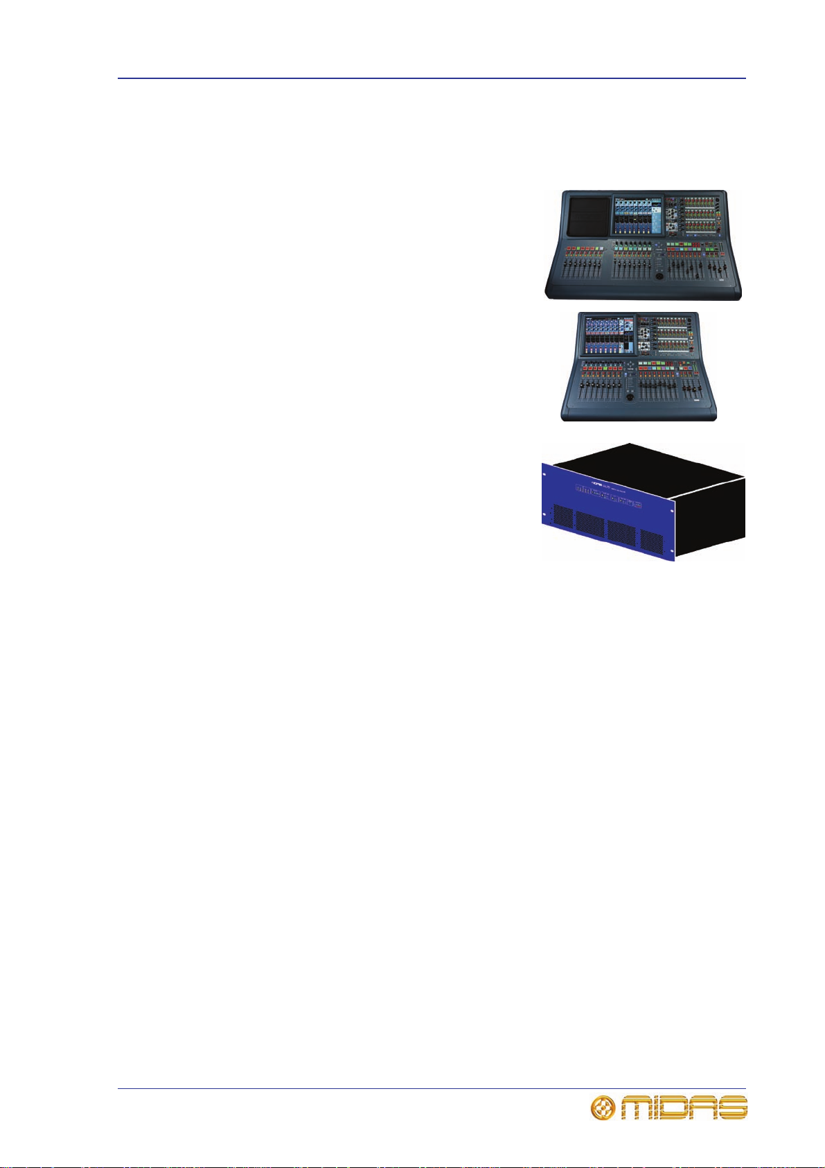
PRO2
PRO2C
System components (standard supply)
The PRO2 Live Audio System can be supplied in either a touring package or install
package. In both packages the following is supplied as standard.
• PRO2 Control Centre: PRO2 (16-channel) or
PRO2C (8-channel).
• DL251 Audio System I/O (1-off): 6U 19” r ack
unit that provides 48 mic/line inputs and 16
outputs.
Touring package
Install package
Offline editor
• Snakes and main cables etc.
To provide a complete audio system, the only other equipment required are mics,
amplifiers and loudspeakers.
In the touring package, the PRO2 is flight-cased. Also included are three 10 m cables
bundled together and supplied on a reel as a ‘snake’ (single copper).
The install package includes short cables, and all the equipment is supplied in cardboard
boxes.
The offline editor is an application that runs on a Mac and can create and edit shows
compatible with any midas digital console.
PRO2 Live Audio System
Owner’s Manual
8 Chapter 2: PRO2 Live Audio System
System configurations
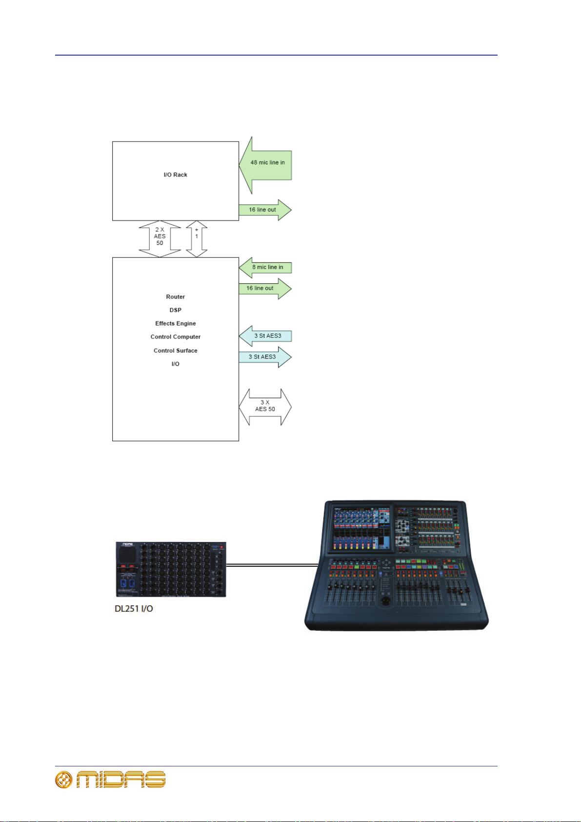
This section shows the basic interconnectivity of a PRO2 Live Audio System and the
possible system configurations.
Basic interconnectivity of a standard PRO2 Live Audio System
PRO2C standard system (compact)
PRO2 Live Audio System
Owner’s Manual

System configurations 9
PRO2 system expanded by adding DL431 input splitters and DL451 modular I/O boxes
Dual PRO2C FOH and MON system using a DL251 split network
PRO2 Live Audio System
Owner’s Manual
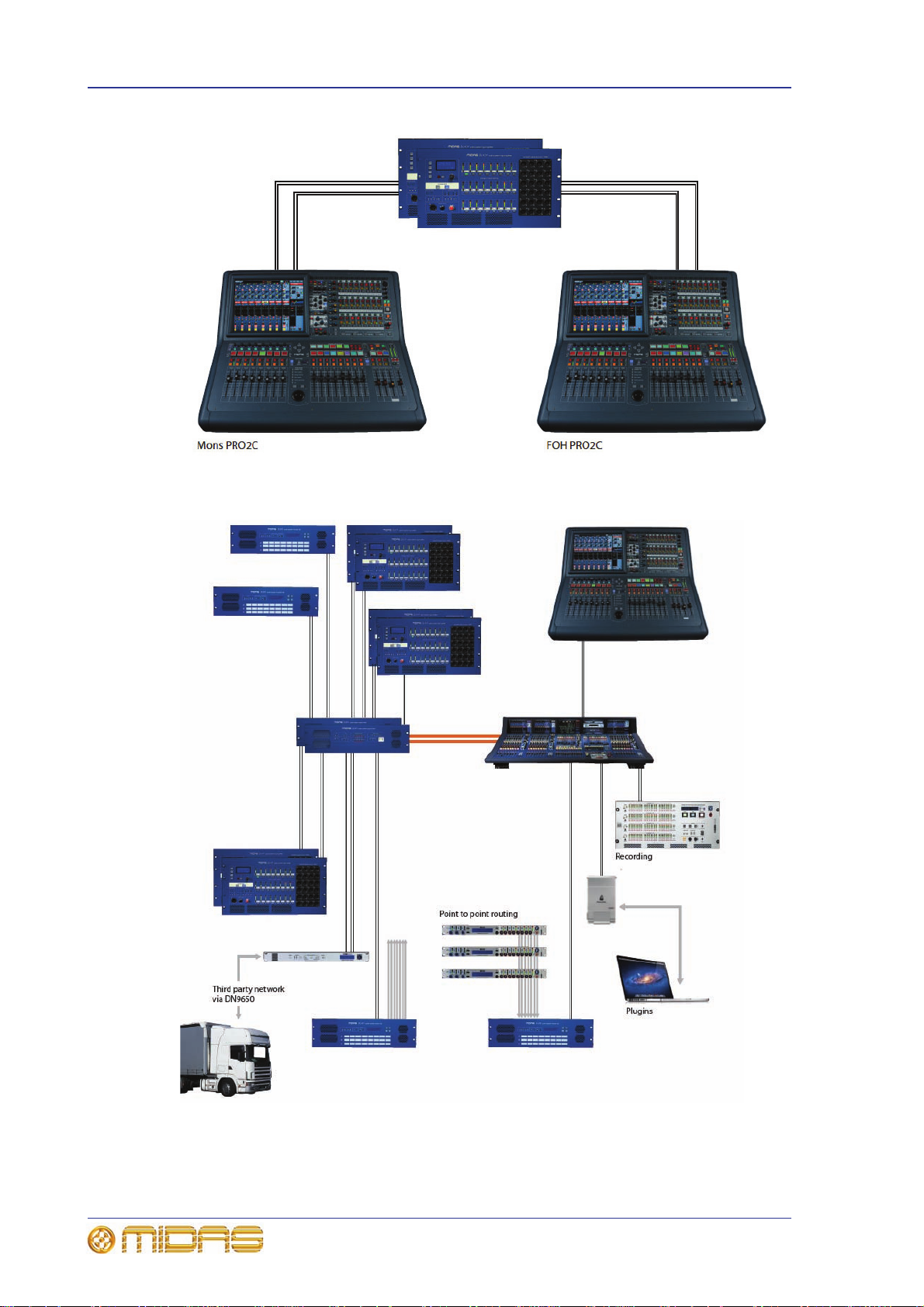
10 Chapter 2: PRO2 Live Audio System
Dual PRO2C FOH and MON system using XL8 DL431 input splitters
PRO2C and XL8 sidecar network with up to 576 inputs and up to 224 simultaneous
channels. The PRO2C control centre and engine are connected to the XL8 network as
an extender. The channel count depends upon the number of I/Os and their
configuration.
PRO2 Live Audio System
Owner’s Manual

Signal flow 11
Signal flow
The control surface contains the DSP engine, which provides the following time-aligned
channels and buses:
• 56 input channels
• 8 aux input channels optionally time-aligned as effects returns or additional input
channels
• 16 aux output channels
• 3 master channels
• 8 matrix channels
• 2 solo buses, routable from all locations providing dual monitor formats
(in ear/wedge)
• 2 master buses, routable from the 56 inputs and 8 aux inputs, and 16 aux buses
• 8 matrix buses, routable from the 56 inputs and 8 aux inputs, 16 aux buses and
3masters
• 16 aux buses, routable from the 56 inputs and 8 aux inputs
Monitor mixing is easily catered for because the master, matrix and aux buses can all
be routed directly from the input channels with independent level controls providing up
to 24 monitor mix buses.
Traditional FOH sub group mixing is easily catered for as the aux buses can be
individually configured to operate post-channel fader and pan (that is, aux gain fixed at
unity).
Auxiliary inputs have two modes, effect return and input channel (default). In input
channel mode they are time aligned to the stage and operate as the input channels
except for they have no dynamics. In effects return mode they are time aligned to the
effects engine and can only route to the matrix and master channels.
PRO2 Live Audio System
Owner’s Manual
12 Chapter 2: PRO2 Live Audio System
16 aux
buses
64 in x 16 out
mix matrix
{}
80 in x 3 out
mix matrix
8 matrix
buses
82 in x 8 out
mix matrix
3 master
buses
{}
{}
56 mic/line inputs 8 mic/line return inputs
2 solo
buses
84 in x 2 out
mix matrix
{}
Bus outputs
Bus inputs
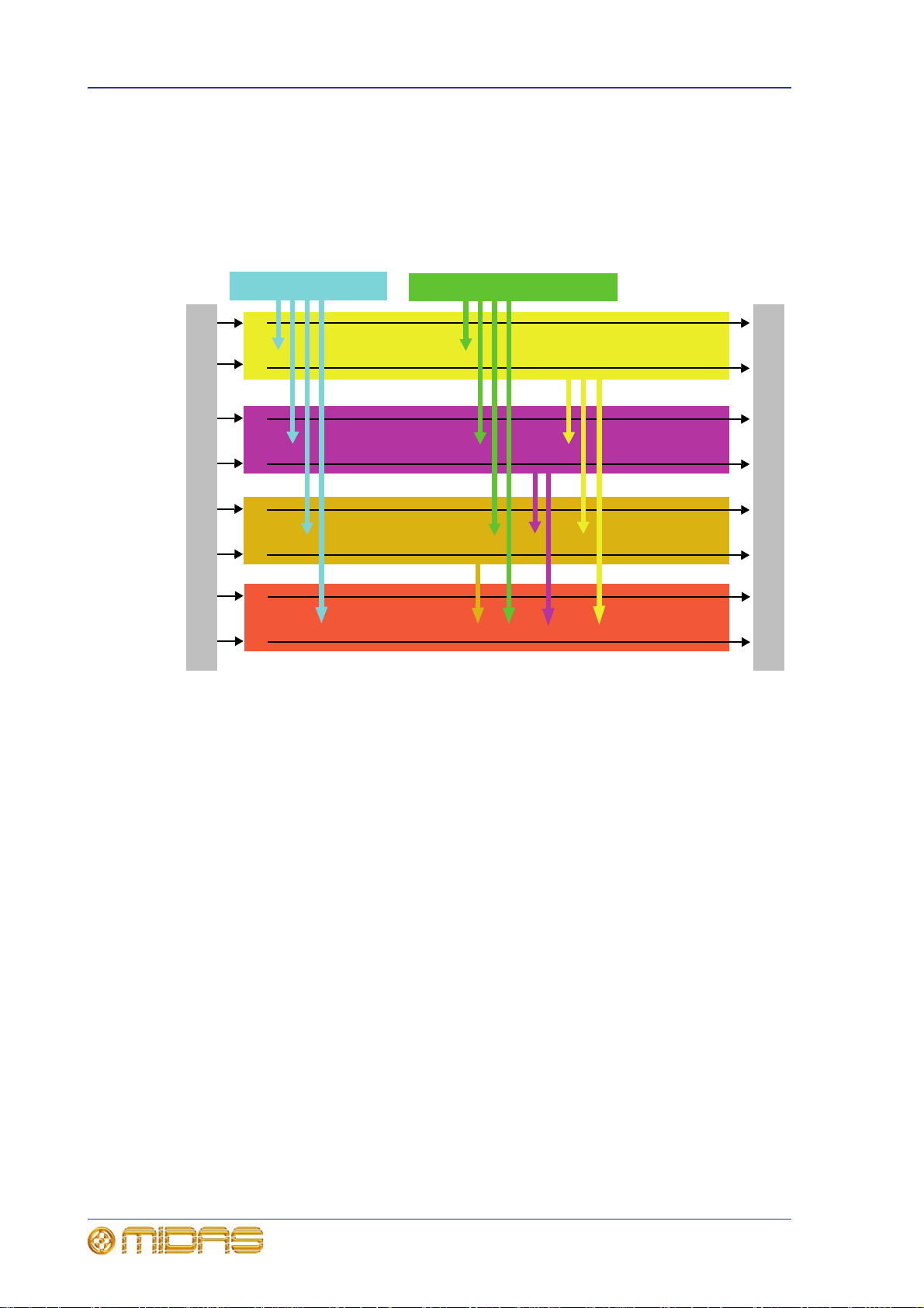
Mix matrix
Ultimately, the mix matrix defines the PRO2 Live Audio System’s capability. Probably
the best way to imagine the mix matrix is to think of an analogue console layout, where
inputs run vertically and buses run horizontally. A mix matrix is usually defined as the
number of buses and the quantity of simultaneously-mixable inputs there are per bus.
The following diagram illustrates the capability within the control centre.
Processing
Although the control centre system allows for considerable insertion of external
processing, it also embodies more than enough internal high quality processing to
eliminate the need for this.
Input channel processing
Each of the 56 full-function input channels has:
• Analogue and digital gain.
• Phase reverse switch.
• Input delay.
• Swept high pass filter with choice of two filter slopes.
• Swept low pass filter with choice of two filter slopes.
• Frequency-conscious compressor with choice of four compression styles.
• Frequency-conscious noise gate with external side chain.
• Insert point.
• Treble E Q filter wi th choice of fou r filter types.
• Parametric hi-mid EQ filter.
• Parametric lo-mid EQ filter.
• Bass EQ filter with choice of four filter types.
• Routing via level controls to 24 mix buses.
• Routing via pan control to left and right master buses.
PRO2 Live Audio System
Owner’s Manual

Processing 13
• Routing to mono master bus.
•Panpot (SIS™).
• Direct output.
Each of the 16 auxiliary inputs has:
• Input gain.
• Source from internal FX or external pool input.
•Fader.
•Panpot (SIS™).
• Routing via level controls to the eight matrix buses.
• Routing via pan control to the left, right and mono master buses.
Mix channel processing
Each of the 16 auxiliary mix buses has:
• Subgroup, auxiliary or mix minus modes.
• Dual mono or stereo pair modes.
• Six-band PEQ.
• Optional 31-band GEQ (replaces PEQ).
• Frequency-conscious compressor with soft clip limiter and choice of five compression
styles.
• Insert point.
• Routing via level controls to the 6 matrix buses.
• Routing via pan control to the left, right and mono master buses.
• Direct input.
Each of the eight matrix buses has:
• Six-band PEQ.
• Optional 31-band GEQ (replaces PEQ).
• Five-mode frequency-conscious compressor with soft clip limiter and external side
chain.
• Insert point.
• Direct input.
Output channel processing
Each of the eight matrix buses has:
• Six-band PEQ.
• Optional 31-band GEQ (replaces PEQ).
• Five-mode frequency-conscious compressor with soft clip limiter and external side
chain.
• Insert point.
• Direct input.
The two master output buses each has:
• Six-band PEQ.
• Optional 31-band GEQ (replaces PEQ).
• Five-mode frequency-conscious compressor with soft clip limiter and external side
chain.
• Insert point.
• Direct input.
PRO2 Live Audio System
Owner’s Manual

14 Chapter 2: PRO2 Live Audio System
Effects processing and GEQs
The PRO2 contains eight mono Klark Teknik (KT) GEQs and eight effects processors as
standard.
The effects processors (six maximum) can be freely chosen from the following:
•Stereo delay.
•Stereo flanger.
•Stereo phaser.
• Stereo harmoniser.
• Stereo reverb (KT DN780).
•Stereo Dynamic EQ.
• GEQ (each effect slot can be sacrificed to gain an additional four GEQ effects).
• Eight channels of SQ1 Dynamics.
Up to 28 mono KT GEQs can be patched into any output. There are many patching
options for the effects processors. They can be patched to any source or destination
within the system and you can even patch directly to and from an effect externally.
Surround capabilities
Theatres and broadcast have differing requirements for surround, and both are catered
for in the PRO2.
Conventional stereo and SIS™ panning is assignable on a channel by channel basis
(channel one can be in stereo while channel two can be in SIS™), as follows:
• Stereo left–right routing to master buses.
• SIS™ left–right–centre routing to master buses.
Three additional surround modes operate as follows:
• Quad (left, right, LS and RS).
• Surround (left, centre, right surround).
• 5.1 surround (left, centre, right, subwoofer (LCRS), LS and RS).
Network
The PRO2’s digital audio network utilises the physical connectivity of Ethernet
(EtherCon® connectors and Cat 5e/Cat6 cable), but replaces its data protocol with
AES50 protocol (implemented as SuperMAC) and the HyperMAC high capacity system,
which are more suited to high quality, low latency audio distribution. The use of the
AES standard allows straightforward interfacing with any third party hardware that also
utilises this connection.
AES50 and HyperMAC connections carry digital audio, control data and standard
Ethernet traffic bi-directionally down a single cable. Cat 5e cable is used for the ‘local’
(24-channel) connections and the single digital ‘snake’
router — is either Cat 5e/Cat6 or fibre optic. The combination of audio, control, clock
and third party Ethernet data in a single network means that the hardware interfaces on
a single RJ45 connection.
All system connections are duplicated for full dual redundancy.
1
— between control centre and
1. The digital snake is equivalent to a 384-channel analogue multi-core cable (192 channels in each
direction).
PRO2 Live Audio System
Owner’s Manual

Resilience to failure (redundancy) 15
Resilience to failure (redundancy)
The PRO2 Control Centre has dual redundant power supplies, so if one fails the other
can carry on working. The N+1 principle is used for the audio, where the AES50 cables
include a redundant spare.
The GUI screen can be used to operate the control centre, even if no control surface
hardware is working.
Latency management
In the interests of reduced latency the primary channel types are restricted to three
time zones and the interconnecting buses are restricted to the time in between.
• First time zone: Input channels, including aux inputs that are set to input channel
mode. (Aux bus time is here.)
• Second time zone: Aux channels, including aux inputs that are set to effects
return mode. (Master and matrix bus time is here.)
• Third time zone: Master and matrix outputs.
Operating system
The PRO2’s operating system is Linux, which is an open-source, stable, proven
operating system (OS). Linux is used in many mission-critical applications worldwide
and has allowed Midas’ software engineers to write a ground-up system that contains
no ‘hidden’ or unused code. This has resulted in an efficient, compact application,
which is quick in operation, quick booting and comparatively easy to debug.
GUI
The PRO2 has a, daylight-viewable, TFT screen that provides overview and detail status
indication. The screen operated using a trackball and two buttons that, between them,
provide the same control as provided by a computer’s mouse.
The supplied USB keyboard lets you insert text into fields on the GUI screen.
Integration of third party hardware
The PRO2 network includes the capability to interface any third party hardware that
uses AES/EBU or AES50 digital audio, or a standard analogue audio interface.
Each PRO2 AES/EBU input and output has a sample rate converter. Synchronisation to
external AES3 interfaces can be:
• Global - via inputs on the routers.
•Local to each input.
• Local to each output (synchronisation to adjacent local output).
Multiple local connections can be at different sample rates.
The use of the AES50 protocol for the transmission of digital audio means that any third
party digital audio hardware that features this connection can be connected to the
Midas network, and will transfer audio to and from the Midas hardware without any
additional interfaces or converters (provided it runs in TDM 96kHz mode). This will be
particularly useful as the protocol gains acceptance with recording and playback
devices, loudspeaker controllers, audio networking systems, digital amplifiers etc.
The PRO2 Control Centre has a DVI connector on the rear panel, so that the control
centre view can be routed to an external monitor.
PRO2 Live Audio System
Owner’s Manual

16 Chapter 2: PRO2 Live Audio System
PRO2 Live Audio System
Owner’s Manual

Chapter 3: About The PRO2 Control
Centre
This chapter introduces you to the PRO2 Control Centre and provides a brief hardware
description.
Overview of the PRO2 Control Centre
The PRO2 Control Centre comprises a combined control surface and graphical user
interface (GUI) that provides an array of easy-to-use controls for the precise
manipulation of audio.
The control surface has been designed to emulate the fast access of an analogue control
surface by presenting things in a familiar, consistent and logical way. This is enhanced
by visual representations on the GUI screen at the top, which also provides extra
functionality.
17
PRO2 (left) and PRO2C control centres
The PRO2 Control Centre is built on a robust Midas steel frame chassis similar to those
used for established Midas analogue products. The frame houses two main bays (three
on the PRO2) that, collectively, provide the primary mixing needs of the engineer.
PRO2 Live Audio System
Owner’s Manual

18 Chapter 3: About The PRO2 Control Centre
G
I
B
H
F
J
E
C
K
D
A
GUI
G
U
I
PRO2 control surface
During show time the functions that require fast access are controlled by control knobs
(rotary encoders), pushbutton switches, faders etc. More complex functions that do not
require this fast access are controlled via the GUI screen using the trackball and left and
right navigational keys.
Main areas of control surface
Item Description
A
B
C
D
E
F
Channel detail areas Contains detail areas, such as the D-zone
(dynamic), E-zone (EQ) and mix buses, that provide a more comprehensive
control of a channel or mix bus by allowing detailed audio parameter
adjustment. Includes mix bus navigation controls.
Outputs The output controls are limited to basic switch functions, such as,
mute, solo, talk and select, along with signal metering, so that all 24
outputs can be shown at the same time. Outputs can be assigned to
channel or mix bay faders. The selected output with be assigned to the
"selected mix" fader on the master bay. The output area does not require
any direct support from the GUI.
Comms Talk, solo, headphones, etc.
Advanced navigation controls For activating advanced navigational
functions, such as flip, MCAs and GEQ.
I zone Operator-assignable device controls.
Automation and USB Scene store/recall and USB connection.
PRO2 Live Audio System
Owner’s Manual

PRO2 control surface 19
Item Description
G
H
I
Input fast zone Contains the operator’s ‘must have now’ controls in eight
input fast strips. Provides faders, meters, mutes, solos and navigation
(LCD) switches for detailed and complex manipulation of multiple channels
within the console. Typically, this would be input channels but aux returns
and output can also be accessed. This is achieved by scrolling to the right
(the order is inputs/returns/aux send/matrix/masters) or by using the
INPUT and OUTPUT buttons.
Eight channel faders and eight horizontal assignable controls operate in
conjunction with a vertical channel detail controller and the GUI screen.
The usable channel fader control can be increased to 16 by activating the
EXTEND button which allows the channel fader to extend over the usual
mix faders (temporarily overriding them).
The additional input bay of the PRO2 (16-channel version) operates in an
identical manner to this area.
Navigation zone For GUI screen navigation via a trackball. Includes a
screen access panel for direct GUI screen access.
Mix fast zone Eight mix faders (with LCD switches) give the operator
primary mix control. To select an output mix, press the OUTPUT button
and scroll left and right. To assign the VCAs to the mix bay faders, press
the VCA button.
Additional input channel faders can be provided by using EXTEND, which
override the mix faders. They attach themselves numerically to right of the
channels assigned to the channel faders. Pressing OUTPUT or a VCA LCD
select button returns them to their previous state (showing either VCAs or
outputs as appropriate).
J
K
The POPulation groups provide instant navigation to a user-defined set of
channels. When a POPulation group is selected, they are mapped to the
input bay faders and, when in EXTEND mode, the mix bay faders.
Masters and area B This section, which does not require any direct
support from the GUI, has three faders (each with LCD switch, meters solo
and mute). By default, these control the left, right and mono master
outputs. However, they can also be overridden for use as an "Area B",
where VCA and POPulation groups can be unfolded to. They are always
independent of the channel and mix faders, that is, they cannot be set to
area A to become channels 9 and 10.
The third fader is the mono channel. This fader is distinct from the other
two, as it can be overridden by the output select buttons. (When unfolding
a VCA or POPulation group to Area B only the first three channels are
accessible.)
monitors Monitor left and right.
PRO2 Live Audio System
Owner’s Manual

20 Chapter 3: About The PRO2 Control Centre
Rear view
Connections
The PRO2 has a rear connector panel that caters for the connection of mains power
leads, AES50 I/O unit(s), USB devices, keyboards, headphones, talk mics,
communications, external monitor, AES3 synchronisation, diagnostics (for service
personnel only), lamp and word clocks (75R).
The control surface houses a USB connector for uploading/downloading show files and
updating the system software, and a connector for a talk mic.
Rear panel connectors (top) and storage USB connector on the control surface
For more information, see Chapter 29 "Panel Connections" on page 227.
Keyboard
A QWERTY keyboard is supplied that is used mainly for inputting text, such as when
configuring a channel or using automation.
External interfaces
Various devices can be used with the PRO2, such as:
• External USB mouse: Instead of using the navigation zone to operate the GUI
screen, you can use an external USB mouse. This can be plugged into one of the
USB connectors on the rear panel of the PRO2. The USB mouse behaves in the
same way as any PC mouse.
• External USB keyboard: You can plug a USB keyboard into one of the USB
connectors on the rear panel of the PRO2.
• MIDI: Standard 5-pin connectors are housed in the rear panel of the PRO2 for use
as MIDI in, out and through ports.
PRO2 Live Audio System
Owner’s Manual

External interfaces 21
• USB: Two USB ports are provided on the rear panel of the PRO2. In addition, there
is a USB port on the control surface (storage section) for removable storage via a
USB memory stick.
• DVI ports for external monitor: The control centre has a screen output DVI
connector on the rear panel of the PRO2 for connecting an external monitor. This
lets you view remotely what is shown on a GUI screen.
PRO2 Live Audio System
Owner’s Manual

22 Chapter 3: About The PRO2 Control Centre
PRO2 Live Audio System
Owner’s Manual

Volume 1:Getting Started
PRO2 Live Audio System
Owner’s Manual


Chapter 4: Setting Up The System
Before installing, setting up or operating this equipment, make sure that
you have read and fully understand all of this section and the “IMPO RTA NT
SAFETY INSTRUCTIONS” at the front of this manual.
This chapter shows you how to set up an PRO2 Live Audio System to its default
configuration.
Note: If you want to set up the PRO2 Live Audio System using a configuration other
than the default, please contact Midas Technical Support for details.
Initial set-up procedure
Initial system set-up basically comprises:
• Unpacking and checking the equipment — see “Unpacking the equipment”
below.
25
• Making up the rack — see “Making up a rack” below.
• Installation — see “Installation” below.
• Connecting up the equipment — see “Connecting up” on page 28.
• Powering the equipment — see “Powering the PRO2 system” on page 30.
• Setting up the I/O rack device (initial patching) — see “Configuring the
devices” on page 60.
• Configuring the DL251 Audio System I/O unit — see the DL251/DL252 Audio
System I/O Operator Manual.
Unpacking the equipment
After carefully unpacking the equipment, check it against the packing list shown in
“System components (standard supply)” on page 7.
Save all packing materials, as they will prove useful if you need to transport the
equipment later.
Inspect the equipment carefully for any sign of damage incurred during transportation.
It has undergone stringent quality control inspection and tests prior to packing and was
in perfect condition when it left the factory. However, if the equipment shows any signs
of damage, notify the transportation company without delay. Only you, the consignee,
may institute a claim against the carrier for damage during transportation.
Installation
Before installing the equipment:
• Make sure the equipment is correctly connected to the protective earth conductor of
the mains voltage supply of the system installation through the mains leads.
• Power to the equipment must be via a fused spur(s).
• Power plugs must be inserted in socket outlets provided with protective earth
contacts. The electrical supply at the socket outlets must provide appropriate
over-current protection.
PRO2 Live Audio System
Owner’s Manual

26 Chapter 4: Setting Up The System
• Both the mains supply and the quality of earthing must be adequate for the
equipment.
• Before connecting up the equipment, check that the mains power supply voltage
rating corresponds with the local mains power supply. The rating of the mains power
supply voltage is printed on the equipment.
Handling the equipment
Completely isolate the equipment electrically and disconnect all cables from the
equipment before moving it.
When lifting or moving the equipment, always take its size and weight into
consideration. Use suitable lifting equipment or transporting gear, or sufficient
additional personnel.
Do not insert your fingers or hand in any gaps or openings on the equipment, for
example, vents.
Avoid inserting or dropping foreign objects, such as paper, plastic, metal etc., into any
gaps or openings on the equipment, for example, vents. If this happens, immediately
disconnect the equipment from the AC mains. Then have the equipment inspected by
the manufacturer's qualified service personnel.
Do not press or rub on the sensitive surface of the GUI screens.
If the glass of the GUI screen is broken, liquid crystals shouldn’t leak through the break
due to the surface tension of the thin layer and the type of construction of the LCD
panel. However, in the unlikely event that you do make contact with this substance,
please wash it out with soap.
Location
Ideally a cool area is preferred, away from power distribution equipment or other
potential sources of interference.
Do not install the equipment in places of poor ventilation.
Do not install this equipment in a location subjected to excessive heat, dust or
mechanical vibration. Allow for adequate ventilation around the equipment, making
sure that its fans and vents are not obstructed. Wherever possible, keep the equipment
out of direct sunlight.
Do not place the equipment in an unstable condition where it might accidentally fall
over.
Make sure that the mains voltage and fuse rating information of the equipment will be
visible after installation.
Electric fields
Caution:
In accordance with Part 15 of the FCC Rules & Regulations, “… changes or
modifications not expressly approved by the party responsible for compliance
could void the user's authority to operate the equipment.”
Should this product be used in an electromagnetic field that is amplitude modulated by
an audio frequency signal (20Hz to 20kHz), the signal to noise ratio may be degraded.
Degradation of up to 60dB at a frequency corresponding to the modulation signal may
be experienced under extreme conditions (3V/m, 90% modulation).
Optional equipment
Unless advised otherwise, optional equipment must only be installed by service
personnel and in accordance with the appropriate assembly and usage regulations.
PRO2 Live Audio System
Owner’s Manual

Making up a rack 27
Special accessories
To comply with part 15 of the FCC Rules, any special accessories (that is, items that
cannot be readily obtained from multiple retail outlets) supplied with this equipment
must be used with this equipment; do not use any alternatives as they may not fulfil
the RF requirement.
Making up a rack
If you are making up a rack, there are careful considerations to be addressed
beforehand, which are outlined in this section.
Outboard equipment racks
To ensure the correct installation and function of the outboard equipment, such as the
DL251 Audio System I/O and DN9696 recorder, racks must meet the following general
requirements.
• Shock mounting (for non-installation environments): The racks must provide
adequate shock protection of the units they house by incorporating appropriatelydesigned shock protection methods, for example, a foam-suspended rack or a frame
suspended on anti-vibration mounts etc.
• Ventilation: Midas rack units have been designed such that their internal ventilation
airflow is drawn in through the front of the unit and expelled though the rear. To
facilitate this, rack design must ensure that cool air can flow freely through the rack
in the same direction, that is, in through the front of the rack and out through the
rear. Situations where the air flows in a circular direction around and through a unit
must be prevented. Midas recommends that racks with fully opening front and rear
doors are used.
Note: Never combine units in the same rack that have been designed for a
ventilation air flow direction other than that for the PRO2 units. To avoid this, we
recommend that any non-PRO2 units are housed separately.
• Rack mount supports: Always secure the rear of the units to the rack via their rear
rack mount support brackets. These brackets are fitted to every PRO2 unit and are
recommended for use in touring applications. The rack mount support fixing hole
centres are at a depth of approximately 395 mm from the front panel (this
dimension may differ slightly on the DN9696).
• Handles on rack case: You must ensure that there are sufficient external handles
fitted to the rack casing to enable the rack to be manoeuvred easily and safely, and
by the amount of personnel suitable for the task. Also, these handles must be fit for
purpose.
• Clearance at rear of units: To ensure an adequate clearance at the rear of the
units, we recommend that the rack depth, that is, the distance from the front rack
strip to the rear of the rack, is a minimum of 700 mm.
• Securing the cables: We recommend that the cables at the rear of the units be
tidied using lacing bars and cable ties. This should provide optimum access to the
rear of the units for connecting other cables, switching the units on/off, etc., and
give maximum visibility of the units’ LEDs for determining communication status,
link status, condition of audio etc.
PRO2 Live Audio System
Owner’s Manual

28 Chapter 4: Setting Up The System
Connecting up
Connect your system according to your requirements. For examples of system
configuration, see “System configurations” on page 8.
To ensure the correct and reliable operation of your equipment, only high quality,
balanced, screened, twisted pair audio cable should be used.
XLR connector shells should be of metal construction so that they provide a screen
when connected to the console and, where appropriate, they should have Pin 1
connected to the cable screen.
All Jack connector shells should be connected to the cable screen.
For more information, see the PRO2 Live Audio System - Set Up Guide (part number
DOC04-DL2SUG1).
Audio connections
This section gives details of the audio connections of the PRO2 Control Centre.
Table 1: Connector pinouts
Connector on rear
panel Example of plug Pinouts Example of socket
Male XLR chassis
connector (output)
Female XLR chassis
connector (mic input)
Ethernet EtherCon®
connector
1 = ground
2 = hot
3 = cold
1 = ground
2 = hot
3 = cold
N/A
PRO2 Live Audio System
Owner’s Manual

Connecting up 29
4
1
3
2
123
Other connections
The section gives details of the other PRO2 Control Centre interconnections.
Description Example Pinouts Example of socket
4-pin, male XLR
chassis connector(s)
on the rear panel for
connecting 12V/5W
1 = N/A
2 = N/A
3 = ground
4 = 12V
lamp(s)
USB type A socket N/A
DVI screen output
N/A
socket for connecting
foot switch socket
for connecting a 1/4”
TRS Jack plug
1 (tip) = foot
switch 1
2 (ring) = foot
switch 2
3 (sleeve) =
ground
The diagnostics socket is for service personnel use only.
PRO2 Live Audio System
Owner’s Manual

30 Chapter 4: Setting Up The System
Powering the PRO2 system
The internal power supplies are of the switch mode type that automatically sense the
incoming mains voltage and will work where the nominal voltage is in the range
100VAC to 240VAC.
Each mains inlet is to be sourced from its own separate wall-mounted
mains outlet socket. Otherwise, their mains sources must be suitably
distributed so as to meet local safety regulations.
When removing the equipment’s electric plugs from the outlets, always
hold the plug itself and not the cable. Pulling out the plug by the cable can
damage it.
Never insert or remove an electric plug with wet hands.
Before switching the PRO2 on/off, make sure that all monitor loudspeaker
power amplifiers are turned off or muted.
The following details the recommended power up and power down procedures for the
PRO2 system.
>> To power up the PRO2 system
DO NOT switch on the speaker sub-system until after the start-up of the
PRO2 system has been completed.
After all PRO2 system interconnections have been made, start up the PRO2 system:
1 Make sure that all of the PRO2 system equipment is switched off, that is, the
PRO2 Live Audio System, speaker sub-system and DL251 Audio System I/O.
2 Switch on the PRO2 Control Centre (see “To switch on the PRO2 Control Centre”
on page 31).
3 On the PRO2 Control Centre, move all of the monitor and master channel faders
to the minimum position and mute all of the master channels.
4 Switch on the DL251 Audio System I/O.
5 After the status LEDs (top of the GUI screen on the PRO2 Control Centre) turn
green, switch on the speaker sub-system.
6 Switch on the audio source and start playing the audio.
7 On the PRO2 Control Centre, check that the audio inputs are routed to the master
channels. Then, unmute the master channels and gradually increase their faders,
while listening to the sound levels from the speakers.
If there are no sounds at all from the speakers when the faders are at maximum, move
the faders to below the 0dB level and check if the audio is muted somewhere along the
input paths and also check that the individual speakers are switched on. If there is still
no sound from the speakers, contact Midas Technical Support.
>> To power down the PRO2 system
BEFORE switching off any of the PRO2 system components, make sure to
mute the audio from the speakers and switch off the speaker sub-system.
1 Mute the audio from the speakers and switch off the speaker sub-system.
2 Switch off the DL251 Audio System I/O.
3 Switch off the PRO2 Control Centre (see “To switch off the PRO2 Control Centre”
on page 31).
PRO2 Live Audio System
Owner’s Manual

Switching the PRO2 Control Centre on/off 31
Switching the PRO2 Control Centre on/off
Carry out the following to switch the PRO2 Control Centre on/off in a safe manner.
>> To switch on the PRO2 Control Centre
Before switching the PRO2 on, make sure that all monitor loudspeaker
power amplifiers are turned off or muted.
After connecting up the audio cables, carry out the following:
1 Plug one of the control centre’s mains cables into a mains power outlet and then
connect the IEC plug to a mains inlet socket on the rear of the PRO2.
2 Do the same with other mains cable. Make sure you connect the mains cable
to a separate mains outlet.
3 Make sure that all monitor loudspeaker power amplifiers are turned off or muted
and then switch on both mains on/off switches, one after the other. Do not
switch them on simultaneously.
4 The control centre will power up; the GUI will display the default screens and all
the controls will be set to default. You are now ready to start using the PRO2
control centre.
>> To switch off the PRO2 Control Centre
1 Make sure you have saved any shows, scenes or settings you require (see
“Saving your show files to a USB memory stick” on page 91).
2 At the GUI, choose homePreferencesShutdown System.
3 At the Shutdown ENTIRE system? prompt, click OK. This initiates the
shutdown down sequence.
During the shutdown sequence the GUI screens will shutdown and all of the LCD
select buttons on the control surface will turn red.
When the shutdown sequence has finished the LCD select buttons on the control
surface will turn green, and the appropriate ones will also display text messages,
accordingly.
During the shutdown sequence, when the LCD select buttons on the
control surface are red, do not switch off the mains power supply, and
when they are green, it is OK to switch off the mains power supply.
4 Make sure that the shutdown sequence has finished, and then switch off the
mains on/off isolator switches (rear of control centre), one at a time.
5 Disconnect the two mains connectors from the sockets on rear of PRO2 Control
Centre.
PRO2 Live Audio System
Owner’s Manual

32 Chapter 4: Setting Up The System
PRO2 Live Audio System
Owner’s Manual

Volume 2:Basic Operation
Of The PRO2
PRO2 Live Audio System
Owner’s Manual


Chapter 5: Before You Start
This chapter provides useful background information on PRO2 operation.
While this system is a complex, high-tech piece of equipment, we have made it as easy
to use and as user-friendly as possible.
Principles of operation
PRO2 Control Centre operation is based on the concept of colours and groups rather
than ‘layering’ or ‘paging’, which is the case with most digital consoles on the market
today. With so many channels available it is far easier to remember them by their
user-configured individual/group colour and name rather than their channel number.
The control surface is populated with instantly recognisable controls that are logically
distributed in major sections, so that all the controls you need to access most of the
time are always on the control surface, while the remainder are only one action away.
35
Hints and tips
During operation, we recommend that you carry out the following:
• Check what is hidden On the PRO2, unlike on an analogue control surface, some
of the settings and parameters will be hidden from view (stored in the computer
memory of the PRO2). T o make sure there are no hidden surprises, such as a reverb
send left from a previous mix, we recommend that you view unused parameters at
various times during a mix.
• Check the Console Overview screen It is a good idea to frequently monitor the
Console Overview screen (press the HOME button underneath the GUI screen),
which provides at a glance an overview of the control centre’ s status and oper ation.
It shows all the meters and the status condition of faders and some switches, such
as solos and mutes. However, some things will still remain hidden.
Saving your work
We recommend that you save your work regularly while carrying out the procedures
included in this chapter. Not only is this good practice during normal PRO2 operation,
but in this instance it may save you from losing some set-ups that could prove useful
later on. To do this, create a new show (see “To create a new show” on page 82), and
then continue reading through the remainder of this section, following the instructions
carefully. Save your work at convenient points (see “To create a new scene using the
current settings” on page 84 and “To save a show or create a new one from the current
settings” on page 83).
PRO2 Live Audio System
Owner’s Manual

36 Chapter 5: Before You Start
Saving a show versus storing a scene
It is important to understand the differences between saving a show and storing a
scene.
• Storing a scene saves the current settings of the system to the show file. Scene
data is never updated to the show file unless you manually store a scene. The show
file remains unsaved in RAM after storing a scene.
Although the state of the control centre is copied every five seconds, it is not stored
in a scene. Instead, it is placed in the NVRAM (non-volatile random access memory)
of the control centre’s memory, which is a type of RAM that doesn't lose its data
when the power goes off. If the control centre loses power accidentally, these
settings are loaded so that audio parameters are identical, thus avoiding audio level
jumps. When power is lost, the showfile loaded (if any) will not
subsequently be restored, and any unsaved changes to it will be lost.
• Saving a show copies the show file onto the internal solid-state disk of the PRO2.
This provides you with a ‘permanent’ copy, provided you shut down the system
properly as detailed in the following section.
Shutting down the PRO2 Live Audio System properly
When switching off the PRO2 Control Centre, we recommend that you use the shutdown
option of the GUI menu (see “To switch off the PRO2 Control Centre” on page 31).
By using shutdown, the cached copy of the show data, which is maintained by the
system, is automatically stored. Shutdown then uses the current showfile, NVRAM data
and cache files to restore the PRO2 Control Centre to exactly the same state as at
power down; even to the point of loading the unsaved show and placing you at the
correct scene, with non-stored scene data at the control surface.
If you don’t use the Shutdown option the audio parameters are still restored, but the
show and show status (saved/unsaved) cannot be restored automatically. You must
manually reload the show and any unsaved changes will be lost.
PRO2 Live Audio System
Owner’s Manual

Chapter 6: Working With The PRO2
Control Centre
This chapter is intended to familiarise you with the controls (control surface and GUI) of
the PRO2 Control Centre.
Although many controls on the PRO2 Control Centre are similar to their equivalent
analogue-type counterparts, some have been specifically designed for the PRO2,
particularly those for navigation and GUI operation. As you will probably have had
experience on analogue consoles, you will already be familiar with most of the PRO2
controls and their operation.
The GUI can be used to replicate most of the control surface functions and even has
many of its own. However, the emphasis in this chapter — and throughout the
manual — is on using the control surface because, generally, it is quicker and more
intuitive. GUI methods will be included where they are anomalous or there is no control
surface equivalent.
The navigational controls, such as quick access buttons and scroll buttons, are
described in Chapter 7 "Navigation" on page 43, and the ones specifically for
automation can be found in “Managing the scenes” on page 84.
For more information on the operation and function of specific controls, see Volume
“Description” on page 225.
37
About the PRO2 controls
The following table shows some of the controls that can be found on the control surface
of the PRO2.
Type Description Example(s)
Pushbutton Generally two-state, that is, on/off or
enabled/disabled, and backlit or with an integral LCD
for status indication.
Control knob In general, the control knobs (rotary controls) are
touch-sensitive, their adjustment being shown on the
GUI. Some control knobs are backlit to help identify
their current role.
Fader The high quality motorised faders are, similarly to the
control knobs, touch-sensitive.
PRO2 Live Audio System
Owner’s Manual

38 Chapter 6: Working With The PRO2 Control Centre
Detail
area
Status bar
Main area
Type Description Example(s)
LED Status indication.
Meter All of the input, output and monitor peak level meters
on the control surface are shown simultaneously on
the GUI’s Console Overview screen. Additional
peak level meters are included in the direct input and
direct output sections of the input bay and mix bay
channel strips, respectively.
About GUI operation
The GUI is not just an additional feature that enhances control surface operation, it is a
fully-featured tool in its own right. Not only does it show what is happening on the
control surface, but all of its controls are functional. The GUI contains most of the
controls found on the control surface and, in addition, has features that allow
configuration of the PRO2 and provide extra functionality.
For information on how to operate the GUI (for example, using click and drag, using the
screen access buttons), see PRO2 GUI Navigation in the PRO2 Live Audio System
Quick Start Guide.
GUI screen layout
The GUI screen has three distinct areas
(shown right). The status bar is
constantly displayed throughout console
operation, while the main and detail
areas are context-dependent and may be
combined, particularly for GUI menu
screens. During channel operation the
main area will be divided into eight strips
(fast strips) displaying the channels
currently assigned to the channel faders
at the control surface. The detail area
shows a detailed view of the parameters
of the currently selected channel section;
with no channel selected the detail area
will be blank.
To distinguish between channel types, they are colour-coded: inputs = blue, aux inputs
= dark green, aux sends = light green, matrix = black and masters = black.
PRO2 Live Audio System
Owner’s Manual

GUI screen layout 39
1 2 3 4 5 7 86
Detail
area
Status bar
Main area
Status bar
The Status bar, which is always displayed at the top of the GUI screen, contains a
number of elements as shown in the following diagram.
Item Description
1 home button, opens the GUI menu (see “GUI menu flowchart” on
page 284).
2 Screen navigation buttons (see “To find a GUI screen that you recently
opened” on page 46).
3 Name of current screen.
4 “Not Saved” message appears when the scene/preset library file contains
changes that have not been saved.
5 Title of currently selected scene, if any.
6 Tap Tempo section, which shows the current tap tempo time (ms).
GUI cross-hair
7 Copy and paste buttons (see “Using copy and paste” on page 87).
8 User library buttons (see “User library (presets)” on page 88).
The GUI uses a ‘cross hair’ configuration
(shown right) to show which channel is
currently selected in the channel fader
section and also its current detail area
selection.
The detail area can show an output,
while the main area displays input
channel overviews, and vice versa.
You can navigate the eight channel
faders to show output channel
overviews.
PRO2 Live Audio System
Owner’s Manual

40 Chapter 6: Working With The PRO2 Control Centre
Drop-down
arrow
Currently selected
list item
Parameter values displayed on touch
You can configure the PRO2 (see “Setting the user interface
preferences” on page 209) so that the GUI displays the current
value (and dimension) of the control being adjusted.
If you adjust an aux via the mixes section of an input fast strip,
the current value will be shown in the aux’s panel of the GUI input
fast strip.
Operating the GUI screen controls
This section shows you how to operate GUI screen elements, such as buttons, control
knobs, drop-down lists and sliders.
>> To switch a GUI button on/off
Click the button. If it has a status indicator, this will illuminate/extinguish to show that
it is on/off, respectively.
>> To adjust a GUI control knob or fader
Use a drag operation. Move the pointer up/down/left/right for adjustment.
Using drop-down lists
Certain configurable name fields, particularly the signal routing ones, have drop-down
lists that offer a number of preset or context-sensitive options to choose from. Long
lists — containing more options than can be displayed simultaneously — have sliders
that allow you to access all of the options.
>> To select an option from a drop-down list
1 Click the drop-down arrow. The drop-down list
will unfold to display some or all of its contents,
depending on how many items it contains.
2 Do one of the following:
• Click the option you require.
• If necessary, scroll the list (see “To scroll a
drop-down list” below) to display the option, and then click it.
PRO2 Live Audio System
Owner’s Manual

Operating the GUI screen controls 41
C
Scroll box
Scroll bar
Scroll arrow
B
A
Properties
window
List window
Message window
>> To scroll a drop-down list
With the drop-down list displayed, do one of the
following:
• A — Drag the scroll box.
• B — Click the scroll bar. The scroll box will
‘jump’ in the direction of the click to another
position in the scroll bar.
• C — Click an up/down scroll arrow. The scroll
box will ‘jump’ in the direction of the scroll
arrow to another scroll bar position.
Spin buttons
Up/down spin buttons (highlighted right) let you increase/decrease the
attribute or value of an item. For example, the amount of time a signal
is delayed.
Radio buttons
Radio buttons let you choose a single option from a list of
options.
About windows
There are three main types of window you
will encounter when using the GUI:
• Parameter windows contain elements
(parameters) that you can select or edit,
such as options, lists, tick boxes, text
fields etc.
• Alert windows contain text that can be
a prompt or an error message.
Generally, this type of window will
contain a user-editable text field and OK
and CANCEL buttons. [All controls
inhibited until a button - CANCEL or OK is pressed.]
• Option windows have a number of
user-selectable options in the form of a
list, and may include OK and CANCEL
buttons.
Similar to a window found on a PC running a Windows-based operating system, the
window can be moved around the screen, which is useful if you need to see what is
behind it. Also, each window has a close (X) button at its upper-right corner.
>> To close a window
Do one of the following:
• To acknowledge your changes, click OK.
PRO2 Live Audio System
Owner’s Manual

42 Chapter 6: Working With The PRO2 Control Centre
Crossfade
graph
Surround
spatial
diagram
Right arrow
shows that the
option has a
submenu
Blue
background
shows that
option is ready
for selection
• To cancel your changes, click CANCEL.
• Click “(X)” at the upper-right corner of the window.
>> To move a window
Use drag, by clicking on the window’s blue bar (to p) and drag g ing the window where
you want it.
Graphs
Some graphs, such as the crossfade and
surround spatial diagram (shown right),
can be edited on the GUI using drag.
Using the GUI menu
The GUI main menu (shown right) is opened by
clicking the home button, which is constantly
displayed at the upper-left corner of all GUI
screens. To select a submenu option, move the
pointer over the arrow to the right of the menu
option (the submenu will open automatically to
the right of the arrow) and choose the option you
want.
Note: Throughout this manual, menu/submenu
option selection sequences are shown in the
following format: home
General (for example, for choosing the general
preferences screen).
Text editing
For text editing on the GUI (for example, to configure input and output channel names)
you need to attach the supplied external USB keyboard (see “Rear panel connections”
on page 227). You can also use the navigation zone to help you (for example, by
highlighting portions of text using drag).
>> To enter/edit text via the keyboard
1 At the GUI, click within the desired text box. This will place an insertion point in
it; the pointer will change to an I-beam shape.
2 Using the keyboard, edit/type in the new text. Any existing text can be edited or
deleted using the right-click cut, copy and paste options.
3 On the keyboard, press ENTER to exit the text box (or click on an empty area of
the GUI screen). The pointer will change back to an arrow shape.
Preferences
PRO2 Live Audio System
Owner’s Manual

Chapter 7: Navigation
1-8 9-16 17-24 25-32 33-40 41-48 49-56 57-64
This chapter introduces you to PRO2 navigation and shows you how to use the
navigational tools of the PRO2 Control Centre to navigate its channels, groups and
buses.
For information on other types of PRO2 navigation, refer to the following:
• To navigate the scenes in automation, see “Managing the scenes” on page 84.
•To open the GUI’s Patching screen, see “Navigating to the Patching screen” on
page 16.
• To navigate the assignable controls, see Chapter 19 "Assignable Controls" on
page 153.
An introduction to PRO2 navigation
43
The PRO2 provides you with unique navigational controls to quickly and easily access
the items, such as channels, buses, groups and detail areas, that you will require for
mixing.
Navigation is an important feature of the PRO2 Control Centre. One of the advantages
digital consoles have over analogue ones is that their channel count is not limited by
the control surface hardware. However, this means that only a certain amount of
channels can be at the control surface at any time, while the others are ‘hidden’. So,
navigation is required to access these hidden channels whenever you need them.
The PRO2 has advanced navigational functions that are explained in this chapter.
Channel navigation
The channel fader section has eight channels. You can scroll (continuously) from inputs
to outputs and vice versa, but only one type can be assigned to the control surface at
any time. Channels are handled in banks of eight and are shown on the control surface
and GUI in ascending order from left to right.
The following illustration shows the number of analogue consoles it would take to show
all input channels all of the time, as shown in Figure 1 (a massive beast!).
Figure 1: Theoretical analogue equivalent of the PRO2
The following is a list of the types of navigation available on the PRO2.
• Scrolling single channels
• Scrolling assignable control assignments
• Scrolling channels banks
• Swapping the assignable control button assignments
• Scrolling the mix buses
PRO2 Live Audio System
Owner’s Manual

44 Chapter 7: Navigation
• Assigning input channels to the channel fader section
• Assigning output channels to the channel fader section
• Navigating the detail area assignments to the channel faders
• Assigning the mix bay as an additional fader bay
• Assigning VCA groups to the mix bay
• Assigning outputs to the mix bay
For more information, see the PRO2 Live Audio System Quick Start Guide.
Advanced channel navigation
The console’s advanced navigation mode switches can be locked out via the GUI menu
(home
alter the behaviour of the console by defining what will be populating the mix faders if
an output channel is selected. The mix faders can control:
• Main VCAs, and are then called VCA faders.
• Output channels, and are then called Output faders.
• Mix send VCAs, and are then called MCA faders.
PreferencesGeneralUser), but if enabled these switches can be used to
• Output GEQs, and then called GEQ faders.
Advanced navigation buttons on the control surface
Advanced navigational functions include the following, which are detailed in the PRO2
Live Audio System Quick Start Guide. In addition to these is the collapsed flip function,
which is detailed later on.
• Flip mode (FLIP) — channel faders become the mix send contributions to any
selected output channel. Scrolling the detail area (the selected output) will result in
scrolling of the flip sends. There is also a FLIP button on the GUI’s Console
Overview screen.
• Opening the effects window on selecting an output (FX) — when on and an
aux send is selected, the effects processor that the aux is feeding appears on the
channel overview GUI operated by the assignable control knobs.
• Assigning GEQs to mix bay (GEQ) — the mix faders also operate as GEQ faders,
where they are scrollable in groups of four to access all 31 bands of the GEQ. The
default starting frequency is 200Hz to 1kHz.
• Assigning MCA groups to the mix bay (MCA) — the mix faders can operate as
mix control associates (MCAs), where the aux sends on multiple input channels have
an associated master fader that provides overall control. This is similar to how a
VCA fader operates on the main channel faders and MCA faders also have the same
PRO2 Live Audio System
Owner’s Manual

Advanced channel navigation 45
names and channel members as the VCAs. For information on programming MCAs
and VCAs, see “Configuring VCA/POPulation groups” on page 75.
Collapsed flip
With collapsed flip enabled, switching flip on only recalls to control surface aux sends
that are contributing to the selected mix output. Fader bay scrolling changes to banks
of four.
This affects solo, such that any AFL solo is derived post- the aux send contribution level
(and its pan if applicable).
>> To set up collapsed flip
1 At the GUI, choose
home
PreferencesGeneral.
Then click the User tab to open the
Preferences User screen (right).
2 In the User Interface section, click
the Hide Unassigned Channels when
Flipped selection box to tick it.
The console is now ready for collapsed flip operation.
PRO2 Live Audio System
Owner’s Manual

46 Chapter 7: Navigation
Back button
Forward button
About GUI navigation
While the control surface provides instant, one-button access to many controls, the GUI
provides an alternative way of navigating the PRO2 and offers some unique methods of
its own. The GUI menu gives you access to all of the screens that you will need and you
can even navigate backwards/forwards through the screens that you have recently
opened.
Don’t forget that you can access some of the GUI screens directly by using the
buttons in the screen access panel of the navigation zone.
>> To select a channel/group via the GUI
Click a non-control area of the channel. The local detail area will be assigned to the
local channel strip (control surface and GUI).
>> To select a channel/group using the GUI menu
At the GUI, do one of the following:
• To select an input channel, choose home
containing the input channel you want to open (for example, channels 9-16), and
click the desired input channel (for example, IN14).
• To select an output channel, choose home
containing the output channel you want to open (for example, Aux Sen ds 1-16), and
click the desired output channel (for example, AS7).
• To select a VCA/POPulation group, choose home
Then click a non-control area in the desired group (for example, VCA5).
>> To assign a detail area to the output channel strip via the GUI
Click on one of the detail area panels in a GUI fast strip, making sure you avoid a
control; see “GUI mix fast strips” on page 298.
>> To find a GUI screen that you recently opened
Use the back/forward browser buttons to do one of the following:
• To return to the GUI screen you just opened, click
the back button (as shown right).
• To open one of the GUI screens you have recently
visited, click the back/forward buttons. The back
button will take you back through your browser
history , while the forward button goes the opposite
way.
The back/forward buttons, which are always to the right of the home button, are
similar to those on standard browsers found on any PC.
Input Channels. Then, click the bank
Mix & Outputs. Then, click the bank
Control GroupsVCA Groups.
PRO2 Live Audio System
Owner’s Manual

Chapter 8: Patching
This chapter describes the patching function of the PRO2.
Introduction
The patching function is fundamental to PRO2 operation as, until the I/Os have been
correctly patched, you won’t get any audio. Patching is done entirely at the Patching
screen, which is an option in the GUI menu. This screen lets you carry out all the
routing requirements of the PRO2 by providing an easy-to-use interface, where y ou can
select your source and destination patching options, facilitated by a panel of function
buttons. Additionally, the Patching screen lets you set up the
DL251 Audio System I/O unit and any other devices. For example, you can adjust the
analogue gain, select +48V phantom voltage etc.
47
Terms used in PRO2 patching
• Checkpoint: A patching data store point, created by clicking CHECKPOINT.
• Destination: The patch connector to which a signal is routed.
• Device: A diagram on an I/O tab representing a physical rack unit, such as a
line I/O, mic splitter, DN9696, AES50 etc.
• Drag: A method of selecting a block of source patch connectors in the From section
of the Patching screen (see “To select a block of patch connectors in the From
section” on page 65).
• From section: The left portion of the Patching screen, which contains the source
patch connectors.
• Patch connector: A patching point on any of the tabs. For example, an XLR
connector, bus, sidechain compressor, etc.
• Patching: The process of routing a channel/signal from a source to a destination(s).
• Source: The patch connector from which a signal is routed.
• Tab: A ‘sheet’ in the From and To sections that contains a specific group of patch
connectors.
• To section: The right portion of the Patching screen, which contains the
destination patch connectors.
About the Patching screen
The Patching screen has two main areas: a function button panel towards the top of
the screen and a patching area below. The function buttons provide the required
patching functionality and allow I/O tab devices to be set up. The patching area
provides access to all the patch connectors.
The patching area is split equally into two independent sections, called From and To,
which contain the source and destination patch connectors, respectively. The patch
connectors are grouped on tabs according to type. Only one tab per section will be
visible at any time.
The I/O tabs represent the Stage (1 and 3) and FOH racks, and contain graphical
representations (devices) of the units connected in those racks.
PRO2 Live Audio System
Owner’s Manual

48 Chapter 8: Patching
3 4
5
2
1
7
6
Figure 2: A typical Patching screen display
Item Description
1 Function button panel, contains the function buttons that enable patching
and device configuration (see “Patching screen function buttons” on
page 49).
2 Patching area, contains all of the patch connectors on tabs.
3 From section, contains a number of tabs that house all of the patch
connector sources (see “About the tabs in the From and To sections” on
page 50).
4 To section, contains a number of tabs that house all of the patch connector
destinations (see “About the tabs in the From and To sections” on page 50).
5 Status bar that shows the patching status of the inputs and outputs as a
percentage.
6 A pictorial representation of a physical device.
7 Section titles and tab names.
>> To open the Patching screen
Do one of the following:
• At the GUI, choose home
Patching.
• Press the routing / metering button in the navigation zone.
• At the appropriate GUI screen, click the src (source) or dest (destination) button.
The Patching screen will open at the appropriate tab/configuration window.
PRO2 Live Audio System
Owner’s Manual

About the Patching screen 49
Patching screen function buttons
The function panel buttons of the Patching screen are described in the following table.
When a button is selected, its background colour changes to a lighter shade.
Legend Description
SINGLE Lets you patch a single source to a single destination or multiple destinations.
See “Single patching (SINGLE)” on page 66.
SEQ. Lets you select multiple sources and then patch them one by one to their
destinations. With this method, each source can only have one destination.
See “Sequence patching (SEQ.)” on page 66.
AUTO Lets you select a block of sources and patch them all automatically in one go,
simply by selecting a single destination. Any existing patches within the
destination range will be replaced by the new ones. See “Automatic patching
(AUTO)” on page 66.
NONE Clears all currently selected patch connectors from all tabs in the From and To
sections.
LIST Changes the tooltip type from standard to list to help with sequence patching.
This is only available when SEQ. is on (see “List tooltip” on page 59).
CHECKPOINT Sets a patching store point, or snapshot, that contains the patching status at
that instant. There is only one checkpoint available, so each time
CHECKPOINT is clicked the previous checkpoint is overwritten.
RESTORE Reverts patching status to the last checkpoint or, if no checkpoints have been
created, it will revert patching status to the power up condition. All patching
done in the intervening period will be lost.
UNDO Undoes the latest single patch, even if it was part of a multiple patching
operation. Repeated clicks will undo the preceding patching operations, going
back to the last checkpoint, or power up if no checkpoints have been created.
REDO Redoes an undo. This can be repeated for each undo in the previous undo
operation.
CLEAR SEL. Clears all current selections and their patches.
Important:
Unlike the NONE button, which merely removes the current selections
(highlighted in yellow), CLEAR SEL. goes a step further by removing
the patch as well. This will stop any audio that may have been going
through the patched signal.
CLEAR Clears all patching (see “To clear all current patching” on page 67).
Important:
Exercise great caution when using this function. Observe the warning
that appears after clicking this button.
CONFIG Opens the AES50 Device Configuration window, from where you can
configure the device (see “The AES50 Device Configuration window” on
page 62).
PRO2 Live Audio System
Owner’s Manual

50 Chapter 8: Patching
What the Patching screen symbols mean
The following table gives a description of all the symbols that appear on the Patching
screen tabs.
Symbol Description
During patching, this triangle appears under a tab name when its tab
sheet contains a selected patch connector.
Shown at the top of the channel patch connectors, this box aids channel
identification by showing the channel’s user-configured colour.
Insert return patch connector.
Insert send patch connector.
Bus or channel source patch connector.
Bus or channel destination patch connector.
Female XLR chassis patch connector (input).
Male XLR chassis patch connector (output).
Jack patch connector.
Non-functional patch connector, that is, one that cannot be patched.
Compressor sidechain input patch connector.
Gate input patch connector.
DN9696 recorder patch connector.
Set-up button, which opens the device configuration window (see
“Configuring the devices” on page 60 for details).
About the tabs in the From and To sections
The From section (left side of Patching screen) contains all of the source patch
connectors on tabs, and the To section (right side of Patching screen) contains all of
the destination patch connectors on tabs.
Stage I/O tab — From
The Stage I/O tab contains the devices fitted in the stage racks. For a typical display,
see Figure 2 “A typical Patching screen display” on page 48.
PRO2 Live Audio System
Owner’s Manual

About the Patching screen 51
Busses tab — From
The Busses tab allows routing from the
auxes, matrices and master outputs.
This tab can also be accessed directly via
the dest button in the mixes section of the
input channels and in the direct input
section of the output channels (see “Direct
input controls” on page 304).
Dir. Out (Direct Out) tab — From
The Dir. Out (Direct Out) tab allows you to
patch any of the 96 input channels internally.
For example, to an effect or to provide a way
out of the DL251/DL252 Audio System I/O
via a line I/O unit.
This tab can also be accessed directly via the
dest button in the direct output section of
the input channels.
PRO2 Live Audio System
Owner’s Manual

52 Chapter 8: Patching
Ins. Sends (Insert Sends) tab — From
The Ins. Sends (Insert Sends) tab allows
any of the input and output channels to be
routed, primarily to an effects device.
Effects tab — From
The Effects tab allows patching from any of
the effects.
PRO2 Live Audio System
Owner’s Manual

About the Patching screen 53
Mon. (Monitor) tab — From
The Mon. (Monitor) tab allows routing of
the monitor outs and external talk
destination.
This tab can also be accessed via the dest
buttons on the Monitors screen.
Mon. tab output Equivalent on the Monitors screen
Monitor Out A L monitor A output L
Monitor Out A R monitor A output R
Monitor Out B L monitor B output L
Monitor Out B R monitor B output R
Headphone Out L N/A
Headphone Out R N/A
External Talk Destination external talk output
I/O tab — To
The I/O tab in the To section contains the devices fitted in the stage racks (except the
mic splitters).
Inputs tab — To
The Inputs tab allows sources to be routed
to the input channels and returns.
This tab is also accessed from the src button
in the configuration section of the input
channels.
PRO2 Live Audio System
Owner’s Manual

54 Chapter 8: Patching
Dir. In (Direct Input) tab — To
The Dir. In (Direct Input) tab allows you to
patch, for example, effects to the outputs.
This tab is also accessed from the src button
in the configuration section of the output
channels (see “Direct input controls” on
page 304).
Ins. Ret. (Insert Return) tab — To
The Ins. Ret. (Insert Return) tab allows
insert returns to be patched to any of the
inputs and outputs.
This screen is also accessed directly via the
src button in the insert section of both the
input and output channels.
PRO2 Live Audio System
Owner’s Manual

About the Patching screen 55
Sidechains tab — To
The Sidechains tab allows patching to the
compressor and gate of the input and output
sidechains.
Effects tab — To
See “Effects tab — From” on page 52.
Mon. (Monitor) tab — To
The Mon. (Monitor) tab allows routing to
the communications and monitors.
This tab can opened using the src buttons
on the Monitors screen.
Mon. tab input Equivalent on the Monitors screen
Talk Input Source talk input
Talkback Input Source talkback input
Ext Input Source L external input L
Ext Input Source R external input R
PFL Direct Input Source pfl direct input
PRO2 Live Audio System
Owner’s Manual

56 Chapter 8: Patching
Mon. tab input Equivalent on the Monitors screen
AFL Direct Input Source L afl direct input left
AFL Direct Input Source R afl direct input right
Navigating to the Patching screen
You can access the Patching screen from various other screens in the GUI menu,
usually by clicking a source (source) or dest. (destination) button. When you click
one of these buttons, not only will the Patching screen open, but the appropriate tab in
the From/To section will be open as well. For a full list of patching routing on the
PRO2, see “Navigating to the Patching screen” on page 16.
About the devices on the I/O tabs
The following devices will, if selected (see “Setting up the I/O rack device(s)” on
page 62), appear on the I/O tabs of the From/To sections of the Patching screen.
The device options in the following table are available for selection from the device
type drop-down list in the AES50 Device Configuration window (see Figure 3 “The
AES50 Device Configuration window” on page 62).
Device type Description Diagram
DL232A One of three devices that comprise
the DL232; the other two being
“DL232B” and “DL321C”.
DL251A One of three devices that comprise
the DL251 Audio System I/O; the
other two being “DL251B” and
“DL251C”.
DL252A One of three devices that comprise
the DL252 Audio System I/O; the
other two being “DL252B” and
“DL252C”.
N/A Control Surface IO — represents
the eight input and eight output
connectors on the rear panel of the
PRO2.
N/A Monitor /AES3 — represents the
AES3 I/O connectors on the rear
panel of the PRO2.
PRO2 Live Audio System
Owner’s Manual

About the Patching screen 57
Device type Description Diagram
Mic Splitter DL431 Mic Splitter.
Line IO DL451 Modular I/O.
Generic AES50 Audio-only device that is used to
represent the inputs and outputs of
any third party AES50 device.
DN9696 Klark Teknik DN9696 Recorder. Use
up to four of these devices (with IDs
1 to 4) to represent the four AES50
ports for up to 96 channels of
recording/playback.
For more information, go to our
website www.klarkteknik.com.
DL351A One of four devices that comprise the
DL351 Modular I/O. The others are
“DL351B”, “DL351C” and “Dl351D”.
For more information, go to our
website www.midasconsoles.com.
DL351B See “DL351A”.
DL351C See “DL351A”.
None-Unknown Selects no device. N/A
DL351D See “DL351A”. This is not displayed. N/A
PRO2 Live Audio System
Owner’s Manual

58 Chapter 8: Patching
5
4
321
6
Common device features
The device images have certain common features in their layout, as highlighted in the
following diagram, which shows one of the I/O devices.
Item Description
1 Unit type.
2 Unit ID number.
3 Unit name and PRO2-assigned unit number.
4 ‘Spanner’ button, opens the device configuration window (see “Configuring
the devices” on page 60).
5 XLR patch connector, which is male or female, depending on section
location.
6 Patch connector area. (The line I/O device shows the three card slots, A, B
and C.)
PRO2 Live Audio System
Owner’s Manual

Patching tooltips 59
1
2
3
1
3
2
Patching tooltips
Patching uses two types of tooltip — standard and list — to convey useful patching
information about the patch connectors. A tooltip is a transitory object, in the form of a
text box, that only appears while the GUI’s pointer is in the proximity of a patch
connector.
Standard tooltip
The standard tooltip is the default type that appears during all patching operations. The
following diagram shows, typically, the type of information provided by a standard
tooltip.
Item Description
1 Patch connector information panel, contains information on the selected
patch connector, such as, name, ID, device name, device ID etc.
Depending on the device type, a signal level meter appears if the channel is
passing audio.
2 Routing information panel, contains patching information on the selected
patch connector. (If this panel is blank, the patch connector is not
patched.)
3 The patch connector that the tooltip belongs to.
List tooltip
If you are carrying out a sequence operation, you can use the list tooltip to help in
selecting the destinations in the To section. This tooltip, which has a distinctive
translucent orange background, displays a list of the sources still to be patched. The
list is in order of selection, with the first in the queue being at the bottom. You can only
use the list tooltip for sequence operations.
Item Description
1 ID of the patch connector currently under the GUI pointer.
2 List of selected sources still to be patched. Contains channel and device ID
information.
3 The source patch connector currently waiting to be patched. Once patched,
this will disappear from the list and the one immediately above will become
the next available.
PRO2 Live Audio System
Owner’s Manual

60 Chapter 8: Patching
>> To select the list tooltip
Press LIST. (Pressing LIST again will change the tooltip back to the standard type.)
About the patching procedure
Although patching can be thought of as routing/rerouting the console’s incoming,
internal and outgoing signals, in the context of the Patching screen, patching also
encompasses the setting up and configuration of the devices. The patching procedure
is initially carried out after system installation (see Chapter 4 "Setting Up The System"
on page 25 of the operator manual) and comprises:
• Device configuration: Configure the devices by adjusting their parameters as
necessary (see below).
• Setting up the I/O rack device(s): Set up the system devices, such as line I/O
and mic splitter, on the I/O tabs in the From and To sections of the Patching
screen (see “Setting up the I/O rack device(s)” on page 62).
• Patching: Carry out all of the required routing, for example, mics to input channels
(see “How to patch” on page 64).
Configuring the devices
You have the option to configure the devices via the Patching screen. Parameters,
such as gain and +48V phantom voltage, can be set via a device-specific configuration
window.
These configuration settings can be independent of channel data, as (until patched)
they only control the physical unit. If a device is subsequently patched to one or more
channels, the channel(s) control the device, and vice-versa.
The device configuration window also allows control of audio parameters when the
device is used as a direct connection to another device, for example, FOH to stage via a
digital snake, instead of through the DSP. In this case the settings are also saved in the
show file and can be automated, even though the signals are not routed through the
control centre DSP.
As the mic splitter control conforms to the DL431 Mic Splitter Inputs options (Use A
Inputs or Use B Inputs) in the Configuration Preferences section of the
Preferences screen, it is not possible to control both the A and B settings on the mic
splitter from a single console.???
Device configuration procedure
The procedure for configuring a device comprises:
• Opening the configuration window of the device.
• Selecting one of the device’s cards/channel ranges and configuring the available
parameters.
• Repeating for the other cards/channel ranges of the device.
• Repeating for the other devices.
• Closing the device’s configuration window.
Note: The parameters available for a device are dependent on its type.
PRO2 Live Audio System
Owner’s Manual

Configuring the devices 61
32
1
5
4
1
2
About the configuration window
The configuration window, which has a similar format for each device, comprises eight
channel panels and drop-down lists for channel range/card selection. A typical Line I/O
configuration window is used in the following diagram to show the elements that are
common to each device.
Item Description
1 Device ID field, contains the device type and number.
2 Device drop-down list, for device selection. (Diagram shows the drop-down
list selected.)
3 Channel range/card selection list.
4 OK button, saves the changes and closes the configuration window.
5 Channel panel, contains device-specific controls and graphics.
>> To open the configuration window of a device
Click the device’s spanner button (upper right corner of device).
>> To set up/change the configuration of a device
1 In the device configuration
window, choose the device from
the drop-down list. For
example, the FOH line I/O device
(ID11) connected to port 2.
2 From the drop-down list at the
upper-right corner of the
window, choose the
card/channel. For example, the “AES/EBU Card”.
PRO2 Live Audio System
Owner’s Manual

62 Chapter 8: Patching
2
3
4
5
1
3 In a channel, configure its parameters. For example, in
channel “In1” adjust the gain and switch on the +48V
phantom voltage (shown right).
Repeat for the other channels in the card as necessary.
4 Repeat step 2 and step 3 for the other cards as necessary.
5 If necessary repeat step 1 to step 4 for any other devices of
the same type.
6 Click OK.
Setting up the I/O rack device(s)
You can add, remove and set up the devices, such as line I/Os, mic splitters, DN9696s
etc., that are connected to the Stage I/O and FOH I/O racks. This is done via the
AES50 Device Configuration window (see Figure 3 “The AES50 Device Configuration
window” on page 62), which is opened by clicking CONFIG. Here, you can set up the
device’s ID and also the type of cards (modules) fitted in the physical unit. Some of
the device fields may be blank, as they are dependent on the device type.
Figure 3: The AES50 Device Configuration window
Item Description
1 List of Stage and FOH ports with current device assignments.
2 device type: drop-down list, contains a list of the available devices to
choose from.
3 device ID: drop-down list, contains a full list of IDs for the selected device
type. Those already in use will be prefixed with the text “(In use)”.
4 device options: drop-down list(s) on modular I/O units only (for example,
the DL351) from which you can select the card that is actually fitted in the
physical unit. The positions of the drop-down lists are relative to the card
positions in the physical unit.
5 OK button, closes the AES50 Device Configuration window.
PRO2 Live Audio System
Owner’s Manual

Setting up the I/O rack device(s) 63
Device set-up procedure
The device set-up procedure comprises:
• Selecting the port (Stage or FOH) you wish to allocate the device to.
• Selecting the device type.
• Selecting an ID for the device.
• Selecting the options (if any) for the device.
>> To add a device or change its set up
1 Click CONFIG.
2 In the AES50 Device Configuration window, click the port you want to allocate
the device to; these are listed in the far left of the window. For example, choose
“FOH Port 3 (unused)”. The text in the device type: field will change
accordingly. Ports that don’t have a device allocated to them it will have the text
“unused” inside the brackets after their name.
3 In the device type: drop-down list, click the type of device. For example,
choose “Line IO”.
4 In the device ID: drop-down list, click the ID you want for the device. For
example, choose “ID3”.
5 In the device options: drop-down list(s), choose the type of each card fitted in
the physical unit. For example, choose “Analogue 8 Input”.
Repeat for any other cards.
6 Click OK.
>> To remove a device
Select the device from the list in the left of the AES50 Device Configuration window.
Then, choose “None-Unknown” in the In the device type: drop-down list. For more
information, see “To add a device or change its set up” above.
PRO2 Live Audio System
Owner’s Manual

64 Chapter 8: Patching
How to patch
Patching, basically, involves selecting the source patching connectors in the From
section of the Patching screen and then selecting their destination(s) in the To section.
You can select patches singly, or in multiples by using the sequence and automatic
operations.
About the patch connectors
Each patch connector has three possible states, as indicated by its fill colour. The
following table shows what each state signifies (the examples show XLR connectors,
although it applies to any type of patch connector).
Symbol Description
Patch connector is neither selected or patched.
Patch connector is selected, but can be in either a patched or unpatched
condition.
Patch connector is patched, but not selected.
Working with patch connectors
You can select patch connectors one at a time by clicking on them, or you can select
them in blocks by using a drag operation. All of the patch connectors in both th e From
or To sections are on tabs so, before you can select a patch connector, its tab must be
open.
>> To open a tab in the From or To sections
Click the tab title. For example, Ins. Sends (insert sends).
>> To select a single patch connector
Click the patch connector. The effects of clicking a patch connector are shown in the
following table.
Table 2: Effects of clicking a patch connector
Click To do this in the From section To do this in the To section
Select the patch the connector ( ).
Will do one of the following (provided a
source patch connector(s) has been
selected in the From section):
• Select the patch connector ( )
during a single patching operation.
• Patch the patch connector ( )
during either a sequence or an
automatic patching operation.
Otherwise, this has no effect.
PRO2 Live Audio System
Owner’s Manual

How to patch 65
Click To do this in the From section To do this in the To section
Deselect the patch connector , wh ich then
reverts to its previous state (patched
or unpatched ).
Select the patch connector ( ) and all
the ones it is patched to in the To
section. (A green triangle under a tab
title shows that its tab contains one or
more selected patch connectors.)
To quickly check the destinations of a source patch connector, click it. This will
select it and all of its destinations. A green triangle will appear under the name
of any tab in the To section that contains a destination(s).
>> To select a block of patch connectors in the From section
Use a drag operation to create a bounding box
around the desired connections (typically shown
right).
This procedure can only be done during sequence and
multi-patching operations (initiated by the SEQ. and
AUTO buttons, respectively).
Remove the patch ( ).
Remove the patch ( ).
>> To deselect all selected patch connectors
Click NONE.
>> To remove a single patch
In the To section, click the patch connector from which you want to remove the patch.
>> To remove all the patches of a single source
1 Make sure that no patch connectors are selected. If necessary, click NONE.
2 In the From section, click the source patch connector from which you want to
remove all of the patches. (This will select the source patch connector and also
all of its destinations.)
3 Click CLEAR SEL.
>> To remove the patches from all selected patch connectors
Click CLEAR SEL.
>> To clear a block of patch connectors
1 Click NONE.
2 In the From section, select the patch connectors you want to unpatch.
3 Click CLEAR SEL.
4 Click NONE.
PRO2 Live Audio System
Owner’s Manual

66 Chapter 8: Patching
Single patching (SINGLE)
The SINGLE function button allows you to patch a single source to a single destination
or multiple destinations.
>> To patch a single source to a single destination
The following example shows you how to patch an output from a mic splitter to an input
channel.
1 Click SINGLE.
2 In the From section, click the source
patch connector. For example, choose the
first patch connector of a mic splitter. Its
background will change to yellow and a
green triangle will appear under the tab
title.
3 Click the destination patch connector. For
example, in the Inputs tab of the To section,
choose input channel 3 (Mic3). It will now be
patched to the source. If the new patch is carrying
a signal, this audio may be heard, depending on
the settings of the DL251/DL252 Audio System I/
O.
4 Click the source patch connector (From section)
again to complete the patch.
This can also be done by starting another single patch operation or by selecting
another destination patch connector in the To section.
Note: Note: You can also carry out single patching operations using the CLEAR SEL.
and AUTO functions.
>> To patch a single source to multiple destinations
1 Patch the source patch connector to its first destination (see “To patch a single
source to a single destination” on page 66).
2 In the To section, select the other destinations.
Sequence patching (SEQ.)
If you need to do a number of patches, and each has only a single destination, you can
use the sequence function by pressing SEQ. All of the source patch connectors are
selected in the From section before patching them, one by one, in the To section. This
saves you having to go back to the From section for the start of each patch. You can
change the tooltip to the list type by clicking the LIST button (see “Patching screen
function buttons” on page 49) to help you.
Automatic patching (AUTO)
You can patch a block of source patch connectors, just by selecting a single destination.
This is called “automatic patching”. When using automatic patching, note the following:
• Sources are selected in blocks (see “To select a block of patch connectors in the
From section” on page 65).
• You can only select one block of sources.
• Destinations are restricted to a single type.
PRO2 Live Audio System
Owner’s Manual

How to patch 67
• The selected destination forms the start of the automatically patched range of
destinations.
• Sources and destinations are automatically patched in ascending order, the lowest
numbered source and the selected destination forming the first patch.
• Sources will only be patched up to the highest numbered destination of the current
destination type. If there are any sources left over, automatic patching pauses. Y ou
can then patch these by selecting another destination.
>> To automatically patch a block of source channels
1 Click AUTO.
2 In the From section, select the source patch connectors (see “To select a block of
patch connectors in the From section” on page 65).
3 In the To section, choose the destination patch connector that will form the start
of the patched range. For example, input channel 3 (Mic3).
4 Click the destination patch connector.
The sources will be patch in numerical
sequence and in ascending order from
here onwards.
Clearing all current patching
The CLEAR function button clears all current patching, and must be used
with great caution. To alert you of the drastic nature of using this button, a
WARNING appears.
>> To clear all current patching
1 Click CLEAR. The WARNING
window (shown right) will
appear.
2 Heed the warning and do one
of the following:
• If you want to clear all
current patching, click OK.
• To cancel the clear
operation and close the
WARNING, click CANCEL.
PRO2 Live Audio System
Owner’s Manual

68 Chapter 8: Patching
PRO2 Live Audio System
Owner’s Manual

Chapter 9: Basic Operation
Quick
access
button
SWAP button
Channel strip
gain
control
knob
GUI channel strip
Gain/trim section
SWAP
button
This chapter is intended to familiarise you with the PRO2 Control Centre by showing you
how to carry out some basic operations in order to get some audio out of it.
Setting a mic amplifier’s input gain
The PRO2 Control Centre has two input gains per channel, one is the remote gain for
the analogue mic pre (stage box gain) and the other is the digital trim (console gain).
In its default state, the stage box gain is in the channel strip and the console gain is in
each input fast strip. However, you can swap these sections over (by using the gain
swap/[SWAP] button) to give you a more global control of the stage box gain.
69
PRO2 Live Audio System
Owner’s Manual
Figure 4: Gain and filters sections of the input strip
Note: The gain trim control knobs in each input fast strip will adjust whatever has
been ‘swapped’ to their respective strips. The stage box control knob in the input
channel strip always controls the alternative ‘swap’ to the ones shown in the GUI input
fast strips.
>> To set the gain of the stage box/console
1 In the gain trim section of an input fast strip, press the quick access button.
2 Press the SWAP button. This swaps console digital
This selects the input channel and assigns its configuration detail area to the GUI
channel strip (shown above), which contains the SWAP (gain swap) button.
trim to stage box input gain (and vice versa). The
diagram right shows the two types of gain that can
appear in the input gain/trim section at the top of
each GUI input fast strip.

70 Chapter 9: Basic Operation
3 Adjust the gain trim control knob to set the stage box input gain. Range is
shown on the GUI.
Adjust level to suit the Midas pre-amp characteristic; a suitable level could be one
that only just illuminates the yellow LEDs. Drive the mic amps for that ‘Midas
colouration’ — feel free to overdrive if you want.
4 After you have achieved the required gain state, press the SWAP button again to
swap back to console digital trim.
5 Adjust the gain trim control knob to set the console digital trim (gives +20dB to
-40dB continuous trim) for preferred gain structure.
6 Set analogue remotes for initial set-up, then adjust digital trim for showtime.
Setting the high and low pass filters
When switched in, the high and low pass filters have two settings each, selectable via
their respective SLOPE button. These filters can also be set via the GUI.
>> To set a filter
1 In the gain trim section of an input fast strip (see Figure 4, “Gain and filters
sections of the input strip,” on page 69), press the quick access button. This
selects the input channel and assigns its configuration detail area to the GUI
channel strip (shown above), which contains the filters section.
2 In the filters section of the input channel strip, press the filter select button
(high pass or low pass ) to switch the filter in.
3 If necessary press the filter’s SLOPE button to set its slope (dB); its status is
shown on the GUI. For the high pass filter, in = 24dB and out = 12dB, and for the
low pass filter, in = 12dB and out = 6dB.
4 Adjust the high pass/low pass control knob to set filter frequency (Hz). The
ranges are 10Hz to 400Hz for the high pass filter and 2kHz to 40kHz for the low
pass filter.
Important:
Stage box hi pass — the remote stage box contains a 12dB/Oct 30Hz filter. It
is recommended that this is used at all times for optimum A/D performance.
However, it may be bypassed if extremely low frequency performance is
required, for example, when testing the system.
PRO2 Live Audio System
Owner’s Manual

Input equalisation (E zone) 71
Quick access
button
treble
hi mid
lo mid
bass
Input equalisation (E zone)
Use EQ to equalise the input signal via the treble, hi-mid, lo-mid and bass filters, which
are in the input channel strip’s E zone. Treble and bass each have a parametric filter
option with three specific shelving modes. Visual feedback for EQ is via GUI screen
only, which also has a graphical representation of the filter.
>> To EQ the input signal
1 In the desired input fast strip, press EQ to switch the EQ in. This also selects the
channel and assigns the EQ detail area to the GUI channel strip.
2 Do one of the following to select the EQ band:
• In the input fast strip, press the quick access button of the desired band.
• In the E zone, press the treble/bass up/down arrow buttons until the
button/LED of the desired band is illuminated.
On the GUI the currently selected EQ band will have a light coloured background.
For example, treble in the above diagram.
3 In the E zone, adjust the freq, width and gain control knobs to apply EQ as
desired.
4 If you have selected treble or bass, press SHAPE
(E zone) to cycle through the different shelving modes so
that you can audition them. These are the ‘minimum
harmonic disruption’ types, which are only available for
treble (bright, classic and soft) and bass (deep, classic
and warm). For example, the bright shelving mode of
the treble band (shown right) as displayed on the GUI.
Alternatively, you can click the desired SHAPE button in the GUI channel strip.
Note: bright and deep use psychoacoustic phenomena to generate steep slopes that
sound natural. These filters are called “minimum harmonic disruption filters”.
PRO2 Live Audio System
Owner’s Manual

72 Chapter 9: Basic Operation
Quick access
buttons
Channel strip
comp
GUI channel strips
gate
Hard
Medium
Soft
Input dynamics processing (D zone)
This section deals with assigning compressor and gate dynamics processors using the
controls in the input channel strip’s D zone. There are four compressors available —
corrective, adaptive, creative and vintage — each with the option of hard knee, medium
knee and soft knee (see Appendix A "Application Notes" on page 289). Visual feedback
for both compressor and gate is provided by meters in each input fast strip, the
dashboard screen and just above/below the graph, which gives a representation of the
compressor/gate action.
Figure 5: Compressor and gate channel strips
>> To set up a compressor/limiter
1 Select the desired input channel.
2 In the channel strip, press the quick access button in the comp section (see
Figure 5 “Compressor and gate channel strips” above) to select the input
channel’s compressor detail area.
3 Press ON in the comp section to switch the compressor in.
4 Operate the attack, ratio/range (ratio), release, threshold and make up
control knobs (hold has no effect) to apply processing. See “Compressor” on
page 250. You can set up a limiter by using a high threshold and a steep ratio
(greater than 5:1).
5 Press KNEE to audition the different
algorithms (hard knee, medium knee
and soft knee). The effects on the
signal are shown right.
PRO2 Live Audio System
Owner’s Manual

Output processing 73
6 Press MODE to try the different compressor types
(Corrective, Adaptive, Creative and Vintage). For
example, Creative (shown right).
>> To set up a gate
1 Select the desired input channel.
2 In the channel strip, press the quick access button in the gate section (see
Figure 5 “Compressor and gate channel strips” on page 72) to select the input
channel’s compressor detail area.
3 Press ON in the gate section to switch the gate in.
4 Operate the attack, ratio/range (range), release, threshold and hold con trol
knobs (make up has no effect) to apply processing. See “Gate” on page 254.
Output processing
All outputs — except for the returns — have a six-band PEQ with shelving modes on
bands 1, 2 and 6, and have the option of using a GEQ (accessed via a GEQ button in
GUI channel strip). The returns have a similar EQ to that of the inputs channels.
The outputs (except returns) have five compressor modes, which include all of the ones
on the input channels, but with the addition of a shimmer mode. The returns have the
same compressor modes as those of the input channels.
PRO2 Live Audio System
Owner’s Manual

74 Chapter 9: Basic Operation
Input channel
LCD select
buttons
VCA group LCD
select button
Using VCA/POPulation groups
VCA and POPulation groups allow simultaneous adjustment of a number of channels.
Being instantly recognisable, they provide a quick method of bringing particular
channels to the control surface and save you having to remember their name/number.
You can choose channel group associations and also configure the colour and legend of
each group’s LCD select button, which is used for group member assignment and recall.
VCA groups include fader, solo and mute control, whereas POPulation groups merely
bring a group of input channels to a desired area of the control surface for viewing or
adjustment.
Assigning VCA group members
>> To assign channels to a VCA/POPulation group
1 If necessary, assign the VCAs to the mix bay by pressing VCA in the mix bay
section.
2 In the mix bay, press and hold down the LCD select button of the desired VCA.
For example, a VCA group named “Kit”. The button will start flashing when you
are in group member selection mode and the inputs will jump to programme
mode.
3 While still holding down the LCD select button of the VCA, press the LCD select
buttons (just above the channel faders) of the channels that you want as group
members. For example, “Kik 1”, “Hihat” and “Sn1”. If necessary press INPUT
(channel faders section) to assign the input channels to the channel faders and/
or scroll to a new channel bank.
The first three selected channels of a group will comprise area B during two-man
operation. For more information, see “Area B operation” on page 90 and Chapter
17 "Control Groups" on page 143.
4 Release the group’s LCD select button. The group now contains the input
channels you have just chosen and the group will be selected.
5 Press the VCA’s LCD select button again to exit the group.
To quickly see which channels are in a particular VCA group, press its SOLO
button on/off. Monitor this action on the Console Overview screen. Only the
SOLO buttons of channels that are group members will be affected.
PRO2 Live Audio System
Owner’s Manual

Using VCA/POPulation groups 75
VCA Groups
POPulation Groups
Group name
field
Pencil icon
Palette icon
Control knob icon
Fill icon
Configuring VCA/POPulation groups
The default name and associated colour of a group, which appear on its LCD select
button and on the GUI, can be configured to suit your own preference. You can also
globally change the colour of the group members to match the group colour.
Configuration is done via the Group Sheet screen (shown below).
Note: Clicking the control knob icon opens the VCA Groups screen (a submenu of
the Control Groups option), which provides group management control.
>> To access the Group Sheet screen
Do one of the following:
• At the GUI, choose home
Control GroupsGroup Sheet.
• In the navigation zone, press the vcas screen access button.
>> To set up the name of a VCA/POPulation group
Do one of the following:
• Choose from a list of pre-configured names Click the pencil icon of the
group. Then, choose the name from the drop-down list. For example, choose
“E Gtr”.
• Type in a new name Click within the name field of the group and then follow “To
enter/edit text via the keyboard” on page 42.
>> To set up the colour of a VCA/POPulation group
1 Click the palette icon of the group.
2 In the palette (shown right), click the colour you want. For
example, choose blue.
PRO2 Live Audio System
Owner’s Manual
>> To change the colour of all of a group’s members to match that of its
VCA/POPulation group
Click the fill icon of the group. For example, if the colour of the VCA/POPulation is
blue all of its group members will now be blue.

76 Chapter 9: Basic Operation
Quick access button
mix section
GUI channel strip
This transition point, where solid colours
change to translucent, indicates 0dB
across the eight auxes
Bar shows that this
signal is pre-fader
Ramp shows that
this signal is postfader
Bright number and
coloured ramp/bar shows
that this mix bus is
currently selected; the
colour corresponds to its
associated control knob on
the control surface and
GUI detail area
Bright ramp/bar
shows that this
mix bus is on
Dimmed ramp/bar
shows that this
mix bus is off
Setting up a mix
The PRO2 has 24 configurable mix buses, each of which can be aux mixes, subgroups
or mix minus. The aux mixes can also be set up as stereo pairs (restricted to likecoloured buses) or mono. To keep the control surface manageable, access to these
mixes is confined to the mix section in the channel detail area, which can be scrolled up
and down on a ‘virtual’ surface.
Figure 6: Mix section
On the GUI, the bank of mix buses in each input fast strip (see Figure 7 below) are
colour matched, but also show mix bus status information.
Figure 7: Typical mix section in a GUI input fast strip
PRO2 Live Audio System
Owner’s Manual

Setting up a mix 77
>> To select the mix bus mode
1 In the mix bay, select the desired aux channel.
2 In the channel strip, press the quick access button to select the aux’s
configuration detail area.
3 In the GUI channel strip, click MODE repeatedly to cycle
through the mix modes (mix, group and mix minus) to
choose the one you want. The currently selected mix mode is
shown to the right of the MODE button.
group mode is fader only with no pre-fader. In mix minus
mode all buses are initially routed — you have to switch a bus
routing switch on to take it out of the mix. For information
about stereo mix mode, see “Linking two mixes” on page 78.
>> To set up a mono aux
1 Making sure that the mix bus is not linked (to ensure mix is mono), select the bus
2 Select the input channel.
3 In the appropriate mix section, do the following to your chosen mix
Mix bus routing
You can route an aux or matrix (or even master output) to an effect or output. This is
a GUI-only operation, which is done via the GUI channel strip or Patching screen (see
Chapter 8 "Patching" on page 47).
>> To route an aux or matrix to an effect or output
Do one of the following:
• In the GUI channel strip, select the required mix bus
destination from the drop-down list.
mix
mode as mix (see “To select the mix bus mode” above).
(for example, aux 3 or 11 shown right):
• Press PRE to select pre-fader (on) or post-fader (off).
• Press ON to route the aux mix from input to aux output.
• Adjust the level control knob to change the signal level to suit.
• In the GUI channel strip, click dest (shown right). This will
open the Patching screen and the appropriate tab.
•In the Patching screen, route the aux/matrix. For
information on patching, see Chapter 8 "Patching" on
page 47.
PRO2 Live Audio System
Owner’s Manual

78 Chapter 9: Basic Operation
Linking two mixes
You can link two mixes together, which is a GUI only feature. Pairs can only be created
from adjacent mix buses of the same colour, for example, you can link auxes 3 and 4
together, but not 2 and 3.
>> To route an aux or matrix to an effect or output
To link a pair of mix buses, click the
LINK button in the channel strip of
either mix bus. For example, click
LINK of aux 15 to link it to aux 16
(shown right).
Setting the linked parameter options
The shared parameters default to the user-configurable global
default link settings, which are set via the GUI menu (choose
PreferencesGeneral and click the Linking tab).
home
However, you can override these for the pair via the Stereo
Linking Options window (shown right), which is opened by
clicking the st. linking options button (GUI channel strip).
In stereo mix mode the top control knob becomes pan adjust
and the bottom one adjusts level. When creating a stereo mix,
you can use either the odd or even output to link the two
channels, but the mode of the odd channel is used on both.
For details of the parameters that are stereo linked, see
Appendix J "Parameters Affected By Stereo Linking" on
page 461.
PRO2 Live Audio System
Owner’s Manual

Setting up the effects rack 79
Setting up the effects rack
You can set up the effects rack (in the GUI menu’s Effects
screen) to contain any of the eight available effects listed in
the Change Device Type window, in any of the 16 rack
positions. The diagram right shows the rack populated with
all available effects.
The assignable controls (shown in the Delay diagram) are
common to all effects, and let you control effects parameters
via the I zone (output bay’s control surface).
Stereo delay — provides simple
delay line-based effects. Delay
times can be specified manually or
you can use the ‘tempo-tap’ button.
DN780 (stereo reverb) — is a
reverberation device that emulates
the Klark Teknik DN780 Digital
Reverberator/Processor unit and
allows you to create unique acoustic
environments of virtually any type.
Stereo flanger — has one or, if
configured as stereo, two tap delay
lines. One tap is fixed and the other
tap position is modulated to provide
‘thru-zero’ flanging or single tap
modulation when ‘thru-zero’ is off.
Stereo phaser — has one, or if
configured for dual operation, two
stereo phasers connected in serial or
parallel, according to mode setting.
Pitch Shifter (harmoniser) — has
two independent channels that can
independently shift the pitch of
signals up/down to correct poor
pitching or generate harmonies. The
pitch change can also be modulated
as an effect.
8-channel SQ1 Dynamics — is an
emulation of the Klark Teknik
Square ONE Dynamics, which is an
8-channel analogue dynamics
processor. Used for the precise
manipulation of compression
parameters, it also includes gating
for creative and corrective
applications, and channel linking for
stereo/multi-channel operation.
PRO2 Live Audio System
Owner’s Manual

80 Chapter 9: Basic Operation
4
5
3 Band Compressor (stereo
multi-band compressor) — is a
minimum phase shift (analogue
style) implementation that
guarantees coherent band summing,
even at the most extreme crossover
point settings. Each band provides
full control of its compressor’s
action, with partially adaptive time
constants ensuring the most natural
results from even the most variable
sources.
Dynamic Equaliser — is a 4-band
parametric dynamic equaliser, which
is able to provide frequency selective
compression or expansion.
>> To add an effect to the effects rack
1 At the GUI screen, choose homeRack UnitsEffects. Alternatively, press the
effects / graphics screen access button in the navigation zone.
2 Choose the rack position and click within it.
3 In the effect’s window, click Change Device Type.
4 In the Change Device Type window, select the device type.
For example, “Phas er”.
5 Click OK.
PRO2 Live Audio System
Owner’s Manual

Simple routing to master stereo outputs 81
channel strip
6 Change the parameters of the new effect device as
necessary. For example, adjust control knobs, press
buttons etc. You can even change the effect’s name
by editing its name field (upper-left corner of effect).
You can do this via the GUI or from the I zone using
the output bay GUI (see “PRO2 control surface” on
page 18).
7 Click OK to exit. The new effect will appear in the
effects rack.
You can now patch the new effect, which will be on the
Effects tabs of both the From and To sections of the
Patching screen. For information on how to patch, see
Chapter 5 "Patching" on page 23.
Simple routing to master stereo outputs
The following shows you how to obtain audio.
>> To obtain audio
1 Make sure nothing is muted and the master faders are up.
2 In the masters section of the channel strip, press ST (stereo). You should ha ve
audio.
PRO2 Live Audio System
Owner’s Manual

82 Chapter 9: Basic Operation
Automation
PRO2 automation is managed from the Automation screen of the GUI menu, with
support from the automation section of the control surface (output bay).
The Automation screen (a typical example is
shown right) has the following functions and
features:
• Show management — see “Managing the
shows” on page 82.
• Scene management — see “Managing the
scenes” on page 84.
• Event management — see “Additional control
— managing events” on page 85.
• Cue list — shows the scenes and point scenes
in performance order. The cue list include s information such as scene number,
name, notes etc. You can expand and unexpand the po int scenes and ‘zoom’ the list
on/out. It also lets you reorder the scenes.
• Scope — the Recall Scope and Store Scope buttons open the scope screens, from
which you can select the automated controls that you want to leave in/out of a scene
when it is stored or recalled.
• Rehearsal — the Rehearsal button lets you carry out a rehearsal, which will ‘skip’
(leave out) any scenes that you choose.
Note: Note: With no show loaded, the Automation screen will be blank.
>> To open the Automation screen
Do one of the following:
• At the GUI, choose home
• In the navigation zone, press the automation / filing screen access button.
Managing the shows
The four buttons (NEW, LOAD, SAVE and SAVE AS) towards the top of Automation
screen let you create a new show, load an existing show, update the current show or
create a new show using the current settings.
Important:
We recommend that you save your show
settings regularly (see “Saving a show
versus storing a scene” on page 36). The
PRO2 will indicate that there are show
settings to be saved by changing the
background colour of the SAVE button to red
(shown right).
AutomationAutomation.
The eye icon in the Automation screen (just under the ADD MIDI button) opens
the Show window. This window contains a number of filter options, such as empty
scenes, MIDI events etc., that you can choose to exclude from your show.
>> To create a new show
1 Click NEW.
PRO2 Live Audio System
Owner’s Manual
 Loading...