

Page 1

EXTENDER
OPERATORS MANUAL
Klark Teknik Group,
Klark Teknik Building,
Walter Nash Road,
Kidderminster.
Worcestershire.
DY11 7HJ.
England.
Tel:+44 (0) 1562 741515
Fax:+44 (0) 1562 745371
Email: pro_audio_group@compuserve.com
Website: midasconsoles.com
Page 2

Page 3
Walter Nash Road, Kidde rmi nster, Worce ste rs hire. DY11 7H J. England
Tel:
(44) (0) 1562 741515 .
Company Re gistration No: 2414018
abc d abc
SI G N AL P R OC ESSI N G BY D E F I NIT I ON BETTER BY DESIGN DESIGNEDFOR APUREPE RFORMANCE
Fax:
(44) (0) 1562 745371
DECLARATION OF CONFORMITY
Klark Teknik Group (UK) PLC
We,
of, Klark Teknik Building, Walter Nash Road, Kidderminster, Worcestershire, DY11 7HJ
Declare that a sample of the following product:-
Product Type Number Product Description Nominal Voltage (s) Current Freq
Midas Heritage 3000
to which this declaration refers, is in conformity with the following directives and/or standards:-
Directive(s) Test Standard(s)
Generic Standard using EN55022 Limits and Methods
Class B Conduct Emissions
Class B Radiated Emissions
Fast Transient Burst Level 4
Static Discharge Level 4
Earth Continuity, Insulation at 500V
Signed:............................Alex Cooper
Authority:Project Leader
EN 55013: 1990
EN 50082: 1992
EN50081/1 and /2
EN55022
EN55022
EN61000-4-4
EN61000-4-2
EN60204
Date: 1st April, 1999
Attention!
Where applicable, the attention of the specifier, purchaser, installer or user is drawn to special limitations of use
which must be observed when these products are taken into service to maintain compliance with the above
directives. Details of these special measures and limitations to use are available on request and are available
in product manuals.
A Subsidiary ofTelex communications, Inc.
Page 4

Page 5

ATTENTION!
The following special limitations apply to the console and must be observed in order to maintain safety and
electromagnetic compatibility performance:
POWER CONNECTION
The console should only be operated with the power supply connected to ground via its mains supply connector.
CONTROL CONNECTIONS
The console should only be operated with high quality screened control cables. All connector shells should be
of metal construction so that they provide a screen when they are plugged into the console. All DEE connector
shells should be connected to the cable screen. All XLR and DIN connectors should have pin 1 connected to
the cable screen.
AUDIO CONNECTIONS
The console should only be operated with high quality screened twisted pair audio cables. All connector shells
should be of metal construction so that they provide a screen when they are plugged into the console. All JACK
connector shells should be connected to the cable screen. All XLR connectors should have pin 1 connected to
the cable screen.
ELECTRIC FIELDS
If the console is operated in an electromagnetic field that is amplitude modulated by an audio frequency signal,
the signal to noise ratio may be degraded. Degradation of up to 60dB may be experienced under extreme
conditions (3V/m, 90% modulation).
INSTALLATION
There are a number of points to consider when installing a mixing console. Many of these points will have
been addressed before the console is even unpacked but it is worth repeating them.
POSITION
The console should be located in a convenient space commensurate with the use to which the console is being
put. Ideally a cool area is preferred not in close proximity to power distribution equipment or other potential
sources of interference. Provision should be made for some flat surface surrounding the console to prevent
people using it as a table top.
POWER
The power supply should be located as far from the console as the connecting cable will allow. It should be
set for the appropriate line voltage and plugged into the mains outlet using the supplied cable.
THE POWER SUPPLY SHOULD NEVER BE OPERATED
WITH THE MAINS EARTH DISCONNECTED
Please note that the power supply contains LETHALVOLTAGES greatly in excess of the mains voltage and
that its rails can produce extremely large currentswhich could burn out equipment andwiring if shorted.All
testing and servicing should ONLY be carried out by qualified engineers.
Page 6

Page 7

Contents
Midas HS0001 Mono Input Module
Midas HS0003 Input Fader
Midas HS0004 Stereo Input Module
Midas HS0003 Input Fader
Midas Can Interface Kit
Page 1
Page 2
Page 8
Page 13
Page 15
Page 8

Page 9
48V
+25 +35
PAD
+15
O
gain
PRE
direct o/p
5k
1k
20k
freq
15
bell
treble
2k
+/-
400
8k
freq
INS
15
hi-mid
PRE
EQ
500
15
lo-mid
100
2k
+/-
freq
bell
100
15
bass
20
400
freq
60 160
freq
20
C
0
lr
1
PRE
PRE
2
C
0
lr
3
PRE
PRE
4
C
0
lr
5
PRE
PRE
6
C
0
lr
7
PRE
PRE
8
C
0
9
PRE
PRE
10
C
0
11
PRE
PRE
12
C
0
13
PRE
PRE
14
C
0
15
PRE
PRE
16
C
0
lr
17
PRE
PRE
18
C
0
lr
19
PRE
PRE
20
C
0
lr
21
PRE
PRE
22
C
0
lr
23
PRE
PRE
24
C
lr
pan
SIS
MONO
lcr
stereo
image
mute
MIDAS HS0001
+60
0
+10
0
MIDAS HS0001
Mono Input
15
Q
0
15
0
15
Q
0
15
400
0
+6
0
+6
0
+6
0
+6
0
+6lr
0
+6lr
0
+6lr
0
+6lr
0
+6
0
+6
0
+6
0
+6
ST
+18
+15
+12
+9
+6
+3
0
-3
-6
-9
-25
Module
Page 10

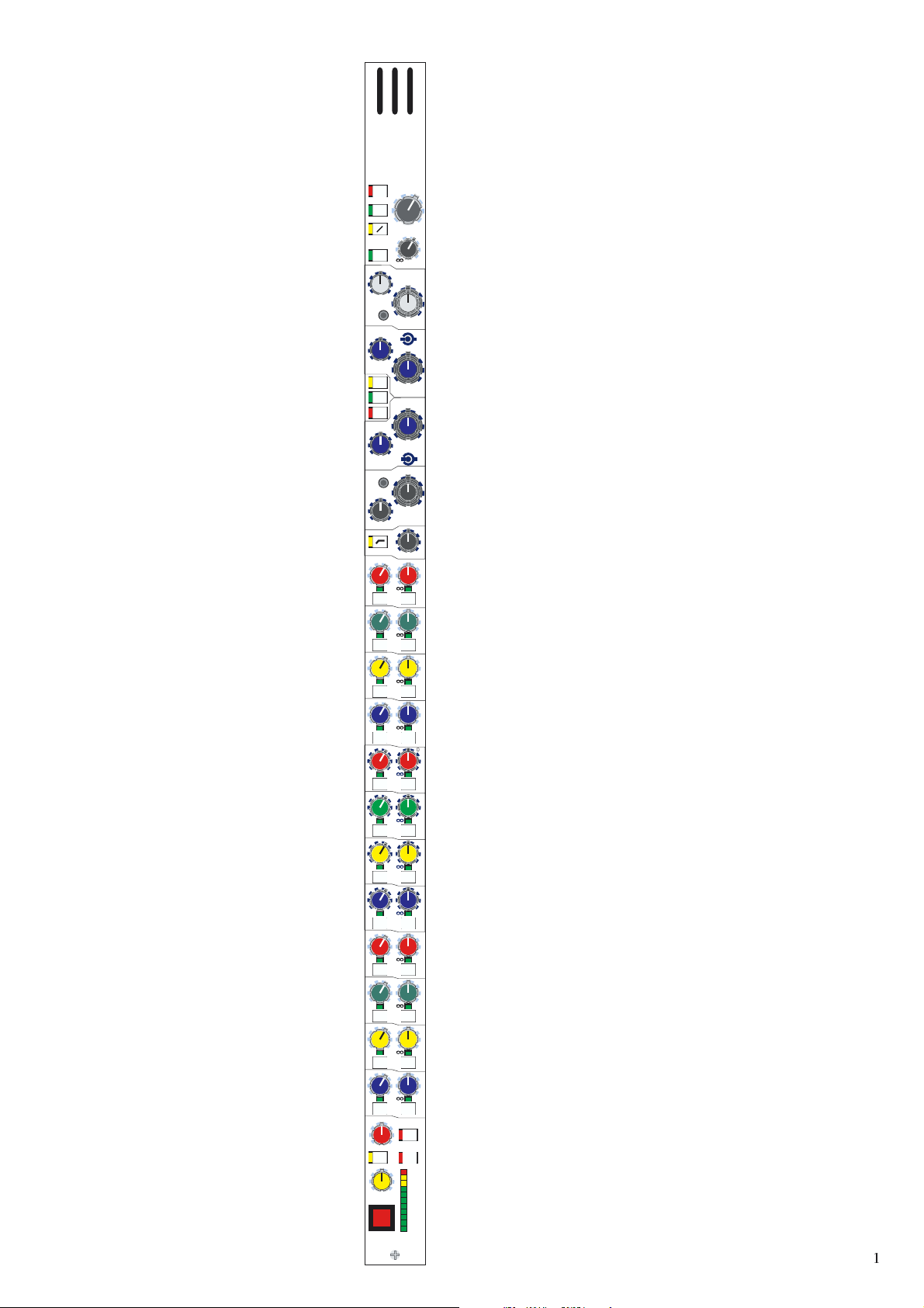
The 48V switch connects 48 volt phantom
power to the input connector which is
suitable for a condenser microphone
or DI box.
The PAD switch gives 25dB of
attenuation to the input signal which will
allow the connection of high output
microphones or line level signals. If the
input amplifier is transformer coupled
(option) the pad greatly reduces the risk
of saturation at very low frequencies.
The PHASE switch activates a 180
degrees phase change within the input
amplifier.
The PRE switch re configures the direct
output to derive signal from the input
channel pre insert and equaliser. It is
important to note that pre insert direct
outputs are also pre mute.
The treble FREQ control gives
continuous adjustment of the frequency
range that the treble equaliser acts on
from 1k to 20k.
The treble BELL switch converts the
treble equaliser from traditional MIDAS
shelving response to full parametric
operation.
The hi mid FREQ control gives
continuous adjustment of the frequency
range that the hi mid equaliser acts on
from 400Hz to 8k.
The INS switch connects the input insert
return signal to the input channel signal
path.
The EQ switch connects the equaliser
into the input channel signal path.
400
48V
+25 +35
PAD
+15
O
PRE
5k
1k
20k
freq
bell
2k
8k
freq
INS
PRE
EQ
gain
direct o/p
0
15
treble
+/-
0
15
hi-mid
+60
0
+10
15
Q
15
The GAIN control gives continuous
adjustment of the input amplifier
gain from + 15dB to + 60dB.
The DIRECT output control gives
continuous adjustment of the direct output
level from + 10dB to off. The output is
derived from the input channel post
equaliser pre fader signal.
The TREBLE (dual concentric top)
control gives continuous adjustment of
boost and cut from + 15dB to - 15dB with
a 0dB centre detent.
The treble WIDTH (dual concentric
bottom) control gives continuous
adjustment of bandwidth from 0.1 to 2
octaves with a 0.5 octave centre detent.
This only operates when the BELL switch
is activated.
The HI MID (dual concentric top) control
gives continuous adjustment of boost and
cut from + 15dB to - 15dB with a 0dB
centre detent.
The hi mid WIDTH (dual concentric
bottom) control gives continuous
adjustment of bandwidth from 0.1 to 2
octaves with a 0.5 octave centre detent.
The insert PRE switch arranges the input
channel signal to pass through the insert
point before the equaliser when activated
and after the insert point when not
activated.
Page 11

The lo mid FREQ control gives
continuous adjustment of the frequency
range that the lo mid equaliser acts on
from 100Hz to 2k.
The bass BELL switch converts the bass
equaliser from traditional MIDAS
shelving response to full parametric
operation.
The bass FREQ control gives continuous
adjustment of the frequency range that
the bass equaliser acts on from 20Hz
to 400Hz.
The HI PASS switch connects the filter
in the input channel signal path before
the insert point and equaliser.
100
20
500
freq
bell
100
freq
15
lo-mid
2k
+/-
15
400
60 160
20
0
0
bass
freq
15
Q
15
400
The LO MID (dual concentric top)
control gives continuous adjustment of
boost and cut from + 15dB to - 15dB
with a 0dB centre detent.
The lo mid WIDTH (dual concentric
bottom) control gives continuous
adjustment of bandwidth from 0.1 to 2
octaves with a 0.5 octave centre detent.
The BASS (dual concentric top) control
gives continuous adjustment of boost and
cut from + 15dB to - 15dB with a 0dB
centre detent.
The bass WIDTH (dual concentric
bottom) control gives continuous
adjustment of bandwidth from 0.1 to 2
octaves with a 0.5 octave centre detent.
This only operates when the BELL switch
is activated.
The HI PASS filter control is
continuously adjustable from 20Hz to
400Hz.
!
Page 12

C
0
0
The aux PRE switches only operate
when in one of the AUX bus modes;
they change the signals sent to the group
busses from post fader to pre fader.
When configured as stereo auxes only the
right switches are active.
lr
1
PRE
2
C
0
lr
3
PRE
4
C
0
lr
5
PRE
6
C
0
lr
7
PRE
8
C
0
9
PRE
10
C
0
11
PRE
12
C
0
13
PRE
14
C
0
15
PRE
16
C
0
lr
17
PRE
18
C
0
PRE
PRE
PRE
PRE
PRE
PRE
PRE
PRE
PRE
+6
+6
+6
+6
+6lr
+6lr
+6lr
+6lr
+6
0
0
0
The configurable group MIX controls
(1 to 24) have two functions:-
i. They operate as bus assign ON/OFF
switches by way of a non latching
0
push/push action with LED status
indication.
ii. They adjust the levels sent from the
input channel to the group busses when
in one of the AUX bus modes.
0
The group mix busses can be configured
in three modes:- MONO AUX,
STEREO AUX or POST PAN GROUP.
This is controlled on a bus by bus basis
0
by the global BUS MODE switches on
the GROUP modules. When configured
as mono auxes the left and right controls
give independent level adjustments from
0
+ 6dB to off. When configured as stereo
auxes the left controls perform a pan
function with a constant power (- 3dB)
law while the right controls give
continuous level adjustment from + 6dB
0
to off. When configured as stereo groups
the level control functions are disabled
such that any assigned busses are sent at
unity gain from the channel post fader,
post pan signals.
0
lr
19
PRE
20
C
0
lr
21
PRE
22
C
0
lr
23
PRE
"
24
+6
PRE
0
+6
PRE
0
+6
PRE
Page 13

The PAN defaults to control the channel
placement within a group or master
stereo mix and has a constant power law
i.e. - 3dB at the centre position.
The ST switch connects the post fader
channel signal to the master stereo bus
via the pan control.
The SIS switch enables the spacial
imaging system which operates in
conjunction with the pan and image
controls. It also acts as a left, centre, right
master bus enable overriding any stereo
and mono master bus assignments.
When the spacial imaging system is
active the IMAGE control can modify
the action of the pan control so as to
place the channel within a three speaker
system. When the image control is fully
clockwise the pan control will operate
in full left, centre, right such that a centre
panned signal will route to the centre
speaker only and will not appear in
either of the left or right outputs. When
the image control is fully anti-clockwise
the pan control reverts to stereo such that
a centre panned signal will route at equal
power to the left and right speakers. All
other Image control positions generate a
composite blend of the stereo and LCR
panning systems so that the optimum
degree of center image focus and
speaker power can be obtained. When
the image control and pan control are
both set central the channel will be
routed with equal power to all three
speakers. Constant power is maintained
at all times so that the image can be
adjusted during the show without any
perceived level change.
C
ST
lr
pan
SIS
stereo
image
lcr
MONO
+18
+15
+12
+9
+6
+3
-25
mute
MIDAS HS0001
-3
-6
-9
The MONO switch connects the post
fader channel signal to the mono
master bus.
0
The METER monitors the peak signal
level of the pre fader input channel.
The MUTE switch mutes the input
channel at all points after the insert send.
The switch can be controlled from
snapshot automation and by automute
scenes.
#
Page 14

Page 15

MIDAS HS0003
Input Fader
safe’s
MUTE
FDR
solo
AUTO AUTO AUTO AUTO AUTO AUTO AUTO AUTO
SET SET SET SET SET SET SET SET
10
1
5
2
0
3
5
4
10
5
6
20
7
30
8
40
9
50
10
dB
safe’s
MUTE
FDR
1
2
3
4
5
6
7
8
9
10
10
10
20
30
40
50
dB
safe’s
MUTE
FDR
solo
10
5
0
5
1
5
2
0
3
5
4
10
5
6
20
7
30
8
40
9
50
10
dB
solo
safe’s
MUTE
FDR
1
2
3
4
5
6
7
8
9
10
10
10
20
30
40
50
dB
safe’s
MUTE
FDR
solo
10
5
0
5
1
5
2
0
3
5
4
10
5
6
20
7
30
8
40
9
50
10
dB
solo
safe’s
MUTE
FDR
1
2
3
4
5
6
7
8
9
10
10
10
20
30
40
50
dB
solo
safe’s
MUTE
FDR
solo
safe’s
MUTE
FDR
10
5
0
5
1
5
2
0
3
5
4
10
5
6
20
7
30
8
40
9
50
10
dB
1
2
3
4
5
6
7
8
9
10
solo
10
5
0
5
10
20
30
40
50
dB
HS0003
MIDASMIDAS
$
Page 16

The SAFE switches disable remote
control of the channels as follows:-
i. The MUTE SAFE removes the channel
mute from the snapshot automation and
automute scenes.
ii. The FADER SAFE removes the
channel fader from the virtual fader
automation and VCA master fader
control including vca mutes.
iii. The AUTO SAFE removes the
channel from the snapshot automation
system only; leaving the automutes,
VCA masters and assignment systems
active.
The SET switch is used to programme
the channel automute and VCA master
assignment. The central controller
MODE and ASSIGN keys select the
desired automute or VCA group and the
SET switch will toggle the channel on
and off with each alternate press.
safe’s
MUTE
FDR
AUTO
SET
10
1
2
3
4
0
5
5
solo
The SOLO switch sends the input channel
signal to the PFL mono and AFL stereo
busses. If the switch is pressed for a short
time it will latch on or off, but if it is held
on for more than 1 second the latching is
disabled and when the switch is released
the channel solo will turn off. As a default
the solo system is auto cancelling so each
new solo cancels the last. This function is
time dependant which allows several solos
to be active as long as they are switched
on at approximately the same time. The
SOLO ADD MODE switch on the
MONITOR module defeats the auto
cancelling and allows multiple channel
monitoring. In this mode input solos have
priority over outputs and will temporarily
override any active output solos. The
input solos also override any active VCA
solos.
The FADER gives continuous adjustment
of the input channel level from
+ 10dB to off.
The STATUS leds are used to show
fader positions and the status of VCA
and MUTE group assignments. The
central controller MODE switches toggle
through the four available states:- VCA
group assignment, MUTE group
assignment, FADER position manual
recall and null, and full automated
VIRTUAL FADER RECALL.
FADER MANUAL RECALL AND NULL
In this mode, the STATUS LEDs are used
to prompt the operator where to move the
fader. If the fader is not at the position
stored in the current recalled snap shot,
one/two LEDs will flash to indicate
where the fader should be. A single
flashing LED indicates that the fader
should positioned next to that LED, if
two LEDs are flashing the fader should
be between the two LEDs. As the fader is
moved closer to the required position the
LED(s) will stop flashing and will be
replaced by a single continuously lit
LED. Once the fader is at the correct
position all LEDs will extinguish.
5
6
7
8
9
10
10
20
30
40
50
dB
HS0003
FADER POSITION CHECK
When a scene's contents are being
"checked" (see automation operation) the
STATUS LEDs will indicate the fader
position stored in the scene by
continuously illuminating one or two
LEDs as appropriate.
VIRTUAL FADER RECALL
When in VIRTUAL FADER mode (see
automation operation) the automation
system will generate a "virtual" fader, set
to the level of the input fader at the time
the snap shot was stored. The level of the
virtual fader is added to the level of the
physical input fader. In this mode the
STATUS LEDs indicate the "position" of
the virtual fader by illuminating a bar of
LEDs starting at - .¥
%
Page 17

48V
+25 +35
PAD
+60
+15
O
gain
c
O
l
r
balance
5k
0
1k
20k
freq
15
15
bell
treble
2k
+/-
Q
0
400
8k
freq
INS
15
15
hi-mid
PRE
0
0
EQ
EQ
500
15
15
lo-mid
100
2k
+/-
Q
freq
0
bell
100
15
15
bass
20
400
freq
60 160
freq
20
400
C
0
0
+6
lr
1
PRE
PRE
2
C
0
0
lr
+6
3
PRE
PRE
4
C
0
0
lr
+6
5
PRE
PRE
6
C
0
0
lr
+6
7
PRE
PRE
8
C
0
0
+6lr
9
PRE
PRE
10
C
0
0
+6lr
11
PRE
PRE
12
C
0
0
+6lr
13
PRE
PRE
14
C
0
0
+6lr
15
PRE
PRE
16
C
0
0
lr
+6
17
PRE
PRE
18
C
0
0
lr
+6
19
PRE
PRE
20
C
0
0
lr
+6
21
PRE
PRE
22
C
0
0
lr
+6
23
PRE
PRE
24
C
r
llr
ST
MONO
18
15
12
9
6
3
0
3
6
9
25
mute
&
MIDAS HS0004
MIDAS HS0004
Stereo Input
Module
Page 18

The 48V switch connects 48 volt phantom
power to both input connectors and is
suitable for condenser microphones or
DI boxes.
The PAD switch gives 25dB of
attenuation in both input signals to allow
the connection of high output
microphones or line level signals. If the
input amplifiers are transformer coupled
(option) the pad greatly reduces the risk
of saturation at very low frequencies.
48V
PAD
+25
+35
The GAIN control gives continuous
adjustment of the input amplifier gains
from + 15dB to + 60dB.
The PHASE switches activate a 180
degree phase change within the input
amplifiers. The upper switch acts on the
left channel and the lower switch acts on
right channel.
The treble FREQ control gives continuous
adjustment of the frequency range that the
treble equalisers act on from 1k to 20k.
The treble BELL switch converts the
treble equalisers from traditional MIDAS
shelving response to bell filters with a
1.5 octave bandwidth.
The hi mid FREQ control gives
continuous adjustment of the frequency
range that the hi mid equalisers act on
from 400Hz to 8k.
400
1k
O
O
5k
freq
bell
2k
freq
+15
balance
20k
15
8k
+60
gain
c
0
treble
hi ‘Q’
0
0
15
The BALANCE control gives continuous
and reciprocal adjustment of the stereo
left and right signal levels by +10dB to
-10dB. This allows fine adjustment of the
left and right signal levels and imaging.
The TREBLE control gives continuous
adjustment of left and right boost and cut
from +15dB to -15dB with a 0dB centre
detent.
The hi mid HI Q control changes the
bandwidth of the hi mid equalisers from
1.5 octave to 0.5 octave.
The INS switch connects the left and
right input insert return signals to the
input channel.
The insert PRE switch arranges the input
channel signals to pass through the insert
points before the equalisers when
activated and after the insert points when
not activated.
The EQ switch connects the left and
right equalisers into the input channel
signal paths.
INS
PRE
EQ
15
hi-mid
15
The HI MID control gives continuous
adjustment of left and right boost and cut
from +15dB to -15dB with a 0dB centre
detent.
'
Page 19

The lo mid FREQ control gives
continuous adjustment of the frequency
range that the lo mid equalisers act on
from 100Hz to 2k.
100
500
freq
2k
0
15
lo-mid
15
hi ‘Q’
The LO MID control gives continuous
adjustment of left and right boost and cut
from +15dB to -15dB with a 0dB centre
detent.
The lo mid HI Q control changes the
bandwidth of the lo mid equalisers from
1.5 octave to 0.5 octave.
The bass BELL switch converts the bass
equalisers from traditional MIDAS
shelving response to bell filters with a
1.5 octave bandwidth.
The bass FREQ control gives continuous
adjustment of the frequency range that
the bass equalisers act on from 20Hz
to 400Hz.
The HI PASS switch connects the filters
in the input channel signal path before
the insert points.
20
bell
100
freq
15
bass
400
60 160
20
freq
0
The BASS control gives continuous
adjustment of the left and right shelving
filters boost and cut from +15dB to -15dB
with a 0dB centre detent.
15
The HI PASS filter control is continuously
adjustable from 20Hz to 400Hz.
400
Page 20

0
0
The aux PRE switches only operate when
in one of the AUX bus modes; they
change the signals sent to the group
busses from post fader to pre fader.
PRE
PRE
PRE
PRE
PRE
PRE
PRE
PRE
PRE
PRE
+6
+6
+6
+6
+6
+6
+6
+6
+6
+6
0
0
0
0
10
0
12
0
14
0
15
16
0
17
18
0
19
20
0
1
2
3
4
5
6
7
8
9
11
13
PRE
PRE
PRE
PRE
PRE
PRE
PRE
PRE
PRE
PRE
+6
+6
+6
+6
+6
+6
+6
+6
+6
+6
0
0
0
The configurable group MIX controls
(1 to 24) have two functions:-
i. They operate as bus assign ON/OFF
switches by way of a non latching
0
push/push action with LED status
indication.
ii. They adjust the levels sent from the
input channel to the group busses when
0
in one of the AUX bus modes.
The group mix busses can be configured
in three modes:- MONO AUX, STEREO
AUX or POST PAN GROUP. This is
0
controlled on a bus by bus basis by the
global BUS MODE switches on the
GROUP modules. When configured as
mono auxes the left and right controls
0
give independent level adjustments of the
levels sent from a mono sum of the
channels left and right sides. The
adjustment is from + 6dB to off . When
configured as stereo auxes the left
0
controls give level adjustment of the left
channel signal levels and the right
controls give level adjustment of the right
channel signal levels. When configured
as stereo groups the level control
0
functions are disabled such that any
assigned busses are sent at unity gain
from the channel post fader, post pan
signals.
0
PRE
PRE
+6
+6
21
22
0
23
24
+6
PRE
0
+6
PRE
Page 21

The left and right PAN controls are used
to place the input channel signals within
a stereo group or stereo master mix. As
well as image placement, the controls
can also adjust the image width from
stereo through mono to reverse stereo
(left and right crossed over). The controls
have a constant power law i.e. -3dB at
the centre position.
The ST switch connects the post fader
channel signals to the stereo master bus
via the pan controls.
The MUTE switch mutes the input
channel at all points after the insert send.
The switch can be controlled from
snapshot automation and by automute
scenes.
C
l
ST
mute
r
l
r
MONO
18
15
12
9
6
3
0
3
6
9
25
The MONO switch connects the post
fader channel signals to the mono master
bus.
The METERS monitor the pre fader peak
signal levels of input channel.
MIDAS HS0004
Page 22

Page 23

MIDAS HS0003
Input Fader
safe’s
MUTE
FDR
AUTO AUTO AUTO AUTO AUTO AUTO AUTO AUTO
SET SET SET SET SET SET SET SET
10
1
5
2
0
3
5
4
10
5
6
20
7
30
8
40
9
50
10
dB
solo
safe’s
MUTE
FDR
1
2
3
4
5
6
7
8
9
10
10
30
10
20
40
50
dB
safe’s
MUTE
FDR
solo
10
5
0
5
1
5
2
0
3
5
4
10
5
6
20
7
30
8
40
9
50
10
dB
solo
safe’s
MUTE
FDR
1
2
3
4
5
6
7
8
9
10
10
10
20
30
40
50
dB
safe’s
MUTE
FDR
solo
5
0
5
solo
10
1
5
2
0
3
5
4
10
5
6
20
7
30
8
40
9
50
10
dB
safe’s
MUTE
FDR
1
2
3
4
5
6
7
8
9
10
10
30
10
20
40
50
dB
safe’s
MUTE
FDR
solo
safe’s
MUTE
FDR
solo
10
5
0
5
1
5
2
0
3
5
4
10
5
6
20
7
30
8
40
9
50
10
dB
1
2
3
4
5
6
7
8
9
10
solo
10
5
0
5
10
20
30
40
50
dB
HS0003
MIDASMIDAS
!
Page 24

The SAFE switches disable remote
control of the channels as follows:-
i. The MUTE SAFE removes the channel
mute from the snapshot automation and
automute scenes.
ii. The FADER SAFE removes the
channel fader from the virtual fader
automation and VCA master fader
control including vca mutes.
iii. The AUTO SAFE removes the
channel from the snapshot automation
system only; leaving the automutes,
VCA masters and assignment systems
active.
The SET switch is used to programme
the channel automute and VCA master
assignment. The central controller
MODE and ASSIGN keys select the
desired automute or VCA group and the
SET switch will toggle the channel on
and off with each alternate press.
safe’s
MUTE
FDR
AUTO
SET
10
1
2
3
5
0
solo
The SOLO switch sends the input channel
signal to the PFL mono and AFL stereo
busses. If the switch is pressed for a short
time it will latch on or off, but if it is held
on for more than 1 second the latching is
disabled and when the switch is released
the channel solo will turn off. As a default
the solo system is auto cancelling so each
new solo cancels the last. This function is
time dependant which allows several solos
to be active as long as they are switched
on at approximately the same time. The
SOLO ADD MODE switch on the
MONITOR module defeats the auto
cancelling and allows multiple channel
monitoring. In this mode input solos have
priority over outputs and will temporarily
override any active output solos. The
input solos also override any active VCA
solos.
The FADER gives continuous adjustment
of the input channel level from
+ 10dB to off.
The STATUS leds are used to show
fader positions and the status of VCA
and MUTE group assignments. The
central controller MODE switches toggle
through the four available states:- VCA
group assignment, MUTE group
assignment, FADER position manual
recall and null, and full automated
VIRTUAL FADER RECALL.
FADER MANUAL RECALL AND NULL
In this mode, the STATUS LEDs are used
to prompt the operator where to move the
fader. If the fader is not at the position
stored in the current recalled snap shot,
one/two LEDs will flash to indicate
where the fader should be. A single
flashing LED indicates that the fader
should positioned next to that LED, if
two LEDs are flashing the fader should
be between the two LEDs. As the fader is
moved closer to the required position the
LED(s) will stop flashing and will be
replaced by a single continuously lit
LED. Once the fader is at the correct
position all LEDs will extinguish.
"
4
5
6
7
8
9
10
5
10
20
30
40
50
dB
HS0003
FADER POSITION CHECK
When a scene's contents are being
"checked" (see automation operation) the
STATUS LEDs will indicate the fader
position stored in the scene by
continuously illuminating one or two
LEDs as appropriate.
VIRTUAL FADER RECALL
When in VIRTUAL FADER mode (see
automation operation) the automation
system will generate a "virtual" fader, set
to the level of the input fader at the time
the snap shot was stored. The level of the
virtual fader is added to the level of the
physical input fader. In this mode the
STATUS LEDs indicate the "position" of
the virtual fader by illuminating a bar of
LEDs starting at - .¥
Page 25

MIDAS
CAN INTERFACE KIT
#
Page 26

PART LIST
Extended internal CAN cable.
Internal RS-232 cable.
CAN interface main, BC3026.
External 5m long CAN cable.
H3000 EXTENDER
INSTRUCTIONS FOR INSTALLATION
Before starting any work ensure consoles areswitched OFF.
Lift out the VCAfader blocks and remove the old internalCAN cable whichruns the lengthof the console.
Place the new extended internal CAN cable in the fader tray and connect all the VCAfader blocks to it. Fit the
VCA fader blocks back in the frame except for channel 17-24. Ensure the free end of the new extended CAN
cable is available at this point.
Remove input modules 22-24,if you need more spacelift out more and somegroup modules if necessary. Draw
the cable through the rectangular pipe located under the left-hand side group modules and catch the cable at the
other end of the pipe at therear of the console.Refit VCAfader block17-24.
Remove the RS-232 connector and it's cable. Put the new CAN interface main board in the old RS-232 hole
and use thread locking compound to ensure the mounting threads do not become loose during operation.
Connect the internal RS-232 cable from SK 1 on Midi connector board (B2949) to socket SK 1 on CAN
interface main board (BC3026). Then connect the extended internal CAN cable to socket SK 2 on the CAN
interface main board.
Finally connect the H3000 main console to the extender console with the external 5m long CAN cable. Port
RS-232 on the main console to port EXT CAN BUS RS232 on the extender console and test the system. Refit
all the remaining input and group modules.
Ensure the main console is running thesame code as theslave (which shouldbe code version 1.5 or higher).
During normal operation the extender console should always be powered up before (or at the same time) as the
main console. This ensures that the main consoles automation system recognizes the extender console is
connected. During a code re-program the slaveand master must bepowered up atthe same time.
5AA .ECKHA
5AA .ECKHA
$
Page 27

Main and extender consoles viewed from above.
Extender console
Figure 1.
Back of main console viewed from above.
*! $
Figure 2.
%
Page 28

HS3000/2000 16 EXTENDER POWER SUPPLY CONNECTION.
The HS3000 16 extender can be powered from 1 or 2 power supplies connected as follows:-
2 X Heritage PSU 1 X Heritage PSU or XL2900
Main Console Extender
2268.00
2268.00
2 X Heritage PSU 2 X Heritage PSU or XL2900
Main Console Extender
2268.00
2268.00
Connection of three power supplies to run the extender and main console is not recommended because the current
sharing is not predictable enough to ensure one of the power supplies does not get overloaded. This is especially
true during power up when nuisance fuseblowing may be experienced.
&
Page 29

48V
+25 +35
PAD
+15
O
gain
PRE
direct o/p
5k
1k
20k
freq
15
bell
treble
2k
+/-
400
8k
freq
INS
15
hi-mid
PRE
EQ
500
15
lo-mid
100
2k
+/-
freq
bell
100
15
bass
20
400
freq
60 160
freq
20
C
0
lr
1
PRE
PRE
2
C
0
lr
3
PRE
PRE
4
C
0
lr
5
PRE
PRE
6
C
0
lr
7
PRE
PRE
8
C
0
9
PRE
PRE
10
C
0
11
PRE
PRE
12
C
0
13
PRE
PRE
14
C
0
15
PRE
PRE
16
C
0
lr
17
PRE
PRE
18
C
0
lr
19
PRE
PRE
20
C
0
lr
21
PRE
PRE
22
C
0
lr
23
PRE
PRE
24
C
lr
pan
SIS
MONO
lcr
stereo
image
mute
MIDAS HS0001
0
0
0
0
ST
+18
+15
+12
+9
+6
+3
-25
+60
0
+10
15
Q
15
15
Q
15
400
0
+6
0
+6
0
+6
0
+6
0
+6lr
0
+6lr
0
+6lr
0
+6lr
0
+6
0
+6
0
+6
0
+6
0
-3
-6
-9
48V
+25 +35
PAD
+15
O
gain
PRE
direct o/p
5k
1k
20k
freq
15
bell
treble
2k
+/-
400
8k
freq
INS
15
hi-mid
PRE
EQ
500
15
lo-mid
100
2k
+/-
freq
bell
100
15
bass
20
400
freq
60 160
freq
20
C
0
lr
1
PRE
PRE
2
C
0
lr
3
PRE
PRE
4
C
0
lr
5
PRE
PRE
6
C
0
lr
7
PRE
PRE
8
C
0
9
PRE
PRE
10
C
0
11
PRE
PRE
12
C
0
13
PRE
PRE
14
C
0
15
PRE
PRE
16
C
0
lr
17
PRE
PRE
18
C
0
lr
19
PRE
PRE
20
C
0
lr
21
PRE
PRE
22
C
0
lr
23
PRE
PRE
24
C
ST
lr
pan
SIS
MONO
lcr
stereo
image
mute
MIDAS HS0001
0
0
0
0
+18
+15
+12
+9
+6
+3
-25
+60
0
+10
15
Q
15
15
Q
15
400
0
+6
0
+6
0
+6
0
+6
0
+6lr
0
+6lr
0
+6lr
0
+6lr
0
+6
0
+6
0
+6
0
+6
0
-3
-6
-9
48V
+25 +35
PAD
+15
O
gain
PRE
direct o/p
5k
1k
20k
freq
15
bell
treble
2k
+/-
400
8k
freq
INS
15
hi-mid
PRE
EQ
500
15
lo-mid
100
2k
+/-
freq
bell
100
15
bass
20
400
freq
60 160
freq
20
C
0
lr
1
PRE
PRE
2
C
0
lr
3
PRE
PRE
4
C
0
lr
5
PRE
PRE
6
C
0
lr
7
PRE
PRE
8
C
0
9
PRE
PRE
10
C
0
11
PRE
PRE
12
C
0
13
PRE
PRE
14
C
0
15
PRE
PRE
16
C
0
lr
17
PRE
PRE
18
C
0
lr
19
PRE
PRE
20
C
0
lr
21
PRE
PRE
22
C
0
lr
23
PRE
PRE
24
C
lr
pan
SIS
MONO
lcr
stereo
image
mute
MIDAS HS0001
0
0
0
0
ST
+18
+15
+12
+60
0
+10
15
Q
15
15
Q
15
400
0
+6
0
+6
0
+6
0
+6
0
+6lr
0
+6lr
0
+6lr
0
+6lr
0
+6
0
+6
0
+6
0
+6
+9
+6
+3
0
-3
-6
-9
-25
48V
+25 +35
PAD
+15
O
gain
PRE
direct o/p
5k
1k
20k
freq
15
bell
treble
2k
+/-
400
8k
freq
INS
15
hi-mid
PRE
EQ
500
15
lo-mid
100
2k
+/-
freq
bell
100
15
bass
20
400
freq
60 160
freq
20
C
0
lr
1
PRE
PRE
2
C
0
lr
3
PRE
PRE
4
C
0
lr
5
PRE
PRE
6
C
0
lr
7
PRE
PRE
8
C
0
9
PRE
PRE
10
C
0
11
PRE
PRE
12
C
0
13
PRE
PRE
14
C
0
15
PRE
PRE
16
C
0
lr
17
PRE
PRE
18
C
0
lr
19
PRE
PRE
20
C
0
lr
21
PRE
PRE
22
C
0
lr
23
PRE
PRE
24
C
ST
lr
pan
SIS
MONO
lcr
stereo
image
mute
MIDAS HS0001
0
0
0
0
+18
+15
+12
+60
0
+10
15
Q
15
15
Q
15
400
0
+6
0
+6
0
+6
0
+6
0
+6lr
0
+6lr
0
+6lr
0
+6lr
0
+6
0
+6
0
+6
0
+6
+9
+6
+3
0
-3
-6
-9
-25
48V
+25 +35
PAD
+15
O
gain
PRE
direct o/p
5k
0
1k
20k
freq
15
bell
treble
2k
+/-
0
400
8k
freq
INS
15
hi-mid
PRE
0
EQ
500
15
lo-mid
100
2k
+/-
freq
0
bell
100
15
bass
20
400
freq
60 160
freq
20
C
0
lr
1
PRE
PRE
2
C
0
lr
3
PRE
PRE
4
C
0
lr
5
PRE
PRE
6
C
0
lr
7
PRE
PRE
8
C
0
9
PRE
PRE
10
C
0
11
PRE
PRE
12
C
0
13
PRE
PRE
14
C
0
15
PRE
PRE
16
C
0
lr
17
PRE
PRE
18
C
0
lr
19
PRE
PRE
20
C
0
lr
21
PRE
PRE
22
C
0
lr
23
PRE
PRE
24
C
ST
lr
pan
SIS
MONO
lcr
stereo
image
mute
MIDAS HS0001
+60
+10
15
400
0
+6
0
+6
0
+6
0
+6
0
+6lr
0
+6lr
0
+6lr
0
+6lr
0
+6
0
+6
0
+6
0
+6
+18
+15
+12
+9
+6
+3
0
-3
-6
-9
-25
0
15
Q
15
15
Q
48V
+25 +35
PAD
+15
O
gain
PRE
direct o/p
5k
1k
20k
freq
15
bell
treble
2k
+/-
400
8k
freq
INS
15
hi-mid
PRE
EQ
500
15
lo-mid
100
2k
+/-
freq
bell
100
15
bass
20
400
freq
60 160
20
C
0
lr
1
PRE
2
C
0
lr
3
PRE
4
C
0
lr
5
PRE
6
C
0
lr
7
PRE
8
C
0
9
PRE
10
C
0
11
PRE
12
C
0
13
PRE
14
C
0
15
PRE
16
C
0
lr
17
PRE
18
C
0
lr
19
PRE
20
C
0
lr
21
PRE
22
C
0
lr
23
PRE
24
C
lr
pan
SIS
lcr
stereo
image
mute
MIDAS HS0001
0
0
0
0
freq
PRE
PRE
PRE
PRE
PRE
PRE
PRE
PRE
PRE
PRE
PRE
PRE
ST
MONO
+18
+15
+12
+9
+6
+3
-25
+60
0
+10
15
Q
15
15
Q
15
400
0
+6
0
+6
0
+6
0
+6
0
+6lr
0
+6lr
0
+6lr
0
+6lr
0
+6
0
+6
0
+6
0
+6
0
-3
-6
-9
48V
+25 +35
PAD
+15
O
gain
PRE
direct o/p
5k
1k
20k
freq
15
bell
treble
2k
+/-
400
8k
freq
INS
15
hi-mid
PRE
EQ
500
15
lo-mid
100
2k
+/-
freq
bell
100
15
bass
20
400
freq
60 160
freq
20
C
0
lr
1
PRE
PRE
2
C
0
lr
3
PRE
PRE
4
C
0
lr
5
PRE
PRE
6
C
0
lr
7
PRE
PRE
8
C
0
9
PRE
PRE
10
C
0
11
PRE
PRE
12
C
0
13
PRE
PRE
14
C
0
15
PRE
PRE
16
C
0
lr
17
PRE
PRE
18
C
0
lr
19
PRE
PRE
20
C
0
lr
21
PRE
PRE
22
C
0
lr
23
PRE
PRE
24
C
ST
lr
pan
SIS
MONO
lcr
stereo
image
mute
MIDAS HS0001
+60
0
+10
0
15
Q
0
Input Crib Sheet
15
0
15
Q
0
15
400
0
+6
0
+6
0
+6
0
+6
0
+6lr
0
+6lr
0
+6lr
0
+6lr
0
+6
0
+6
0
+6
0
+6
+18
+15
+12
+9
+6
+3
0
-3
-6
-9
-25
Inputs
to
Notes:
Input No
Page 30

 Loading...