

Page 1

F16, F24 and F32
Professional Audio Mixing
Consoles
Operator Manual
Midas Klark Teknik Ltd.,
Klark Industrial Park,
Walter Nash Road,
Kidderminster.
Worcestershire.
DY11 7HJ.
England.
Tel: +44 1562 741515
Fax: +44 1562 745371
Email: info@midasklarkteknik.com
Website: www.midasconsoles.com
VeniceF — Operator Manual
DOC02-VENICEF Issue A — December 2010
In line with the company’s policy of continual improvement, specifications and function may be
subject to change without notice. This document was correct at the time of writing. E&OE.
© Red Chip Company Ltd.
Page 2

Page 3

IMPORTANT SAFETY INSTRUCTIONS
The lightning flash with arrowhead symbol within an equilateral triangle is
intended to alert the user to the presence of uninsulated “dangerous voltage”
within the product's enclosure that may be of sufficient magnitude to constitute a
risk of electric shock to persons.
The exclamation point within an equilateral triangle is intended to alert the user
to the presence of important operating and maintenance (servicing) instructions
in the literature accompanying the product.
1 Read these instructions.
2 Keep these instructions.
3 Heed all warnings.
4 Follow all instructions.
5 Do not use this apparatus near water.
6 Clean only with a dry cloth.
7 Do not block any of the ventilation
openings. Install in accordance with the
manufacturer’s instructions.
8 Do not install near any heat sources such
as radiators, heat registers, stoves, or
other apparatus (including amplifiers) that
produce heat.
9 Do not defeat the safety purpose of the
polarized or grounding-type plug. A
polarized plug has two blades with one
wider than the other. A grounding type
plug has two blades and a third grounding
prong. The wide blade or the third prong
are provided for your safety. If the
provided plug does not fit into your outlet,
consult an electrician for replacement of
the obsolete outlet.
10 Protect the power cord from being walked
on or pinched particularly at plugs,
convenience receptacles and the point
where they exit from the apparatus.
11 Only use attachments/accessories
specified by the manufacturer.
12 Use only with the cart, stand,
tripod, bracket, or table
specified by the
manufacturer, or sold with
the apparatus. When a cart
is used, use caution when moving the
cart/apparatus combination to avoid injury
from tip-over.
13 Unplug this apparatus during lightning
storms or when unused for long periods of
time.
14 Refer all servicing to qualified personnel.
Servicing is required when the apparatus
has been damaged in any way, such as
power-supply cord or plug is damaged,
liquid has been spilled or objects have
fallen into the apparatus, the apparatus
has been exposed to rain or moisture,
does not operate normally, or has been
dropped.
15 Use the mains plug to disconnect the
apparatus from the mains.
16 Warning: To reduce the risk of fire or
electric shock, do not expose this
apparatus to rain or moisture.
17 Warning: Do not expose this
equipment to dripping or splashing
and ensure that no objects filled with
liquids, such as vases, are placed on
the equipment.
18 Warning: The mains plug of the power
supply cord shall remain readily
operable.
Page 4

INSTRUCTIONS DE SÉCURITÉ IMPORTANTES
Le symbole représentant un éclair fléché dans un triangle équilatéral a pour but
d'alerter l'utilisateur de la présence d'une "tension dangereuse" non isolée à
l'intérieur du boîtier, pouvant être d'une force suffisante pour constituer un risque
d'électrocution.
Le point d'exclamation dans un triangle équilatéral a pour but d'alerter
l'utilisateur de la présence d'instructions importantes concernant le
fonctionnement et la maintenance, dans la documentation qui accompagne
l'appareil.
1 Veuillez lire ces instructions.
2 Conservez ces instructions.
3 Respectez toutes les consignes de
sécurité.
4 Suivez scrupuleusement toutes les
instructions.
5 N'utilisez pas cet appareil près d'un point
d'eau.
6 Utilisez uniquement un chiffon sec pour le
nettoyer.
7 N'obstruez aucune des ouïes de
ventilation. Installez-le en respectant les
instructions du fabricant.
8 Ne l'installez pas près de sources de
chaleur tels que radiateurs, panneaux
chauffants, étuves, ou autres appareils
produisant de la chaleur (dont les
amplificateurs).
9 Ne pas utiliser d'adaptateur pour
supprimer la prise de terre des prises à
trois fiches. Si la prise fournie ne peut pas
être branchée dans la prise électrique,
adressez-vous à un électricen qui
remplacera la prise obsolète.
10 Protégez le cordon secteur afin que l'on ne
marche pas dessus et qu'il ne soit pas
pincé, surtout au niveau des prises, ou à
l'endroit où il sort de l'appareil.
11 Utilisez exclusivement des fixations et des
accessoires recommandés par le fabricant.
12 Utilisez l'appareil uniquement
avec le chariot, le trépied, le
support ou la table spécifiés
par le fabricant, ou vendus
avec l'appareil. Si un chariot
est utilisé, prenez toutes les précautions
nécessaires lorsque vous devez déplacer
l'ensemble (chariot et appareil) afin qu'ils
ne se renversent pas.
13 Débranchez l'appareil en période d'orage
ou s'il doit rester inutilisé pendant
longtemps.
14 Confiez toutes les réparations et
interventions à un personnel qualifié. Une
intervention est nécessaire si l'appareil a
été endommagé d'une façon ou d'une
autre, si son cordon ou sa prise secteur
ont été endommagés, si du liquide a été
renversé ou si des objets sont tombés à
l'intérieur, ou encore si l'appareil a été
exposé à la pluie ou à l'humidité, s'il ne
fonctionne pas normalement, ou s'il est
tombé.
15 Débrancher l'appareil du réseau électrique
par la prise de secteur.
16 Avertissement : afin de réduire le
risque d'incendie ou de choc
électrique, ne pas exposer cet
appareil à la pluie ou à de l'humidité.
17 Avertissement : n'exposez pas cet
équipement aux éclaboussures et
veillez à ce qu'aucun récipient rempli
de liquide, verre ou vase, ne soit posé
dessus.
18 Avertissement : la prise secteur doit
toujours rester directement
accessible.
Page 5

v
Contents
IMPORTANT SAFETY INSTRUCTIONS . . . . . . . . . . . . . . . . . . . . . . . . . . . iii
INSTRUCTIONS DE SÉCURITÉ IMPORTANTES . . . . . . . . . . . . . . . . . . . . . iv
Contents . . . . . . . . . . . . . . . . . . . . . . . . . . . . . . . . . . . . . . . . . . . v
Chapter 1 Introduction . . . . . . . . . . . . . . . . . . . . . . . . . . . . . . . . .1
Overview of the VeniceF . . . . . . . . . . . . . . . . . . . . . . . . . . . . . . . . . . 1
Key features . . . . . . . . . . . . . . . . . . . . . . . . . . . . . . . . . . . . . . . . . . 3
Control surface . . . . . . . . . . . . . . . . . . . . . . . . . . . . . . . . . . . . . . . . 4
Rear panel . . . . . . . . . . . . . . . . . . . . . . . . . . . . . . . . . . . . . . . . . . . . 5
External connections . . . . . . . . . . . . . . . . . . . . . . . . . . . . . . . . . . . . . 6
Signal flow . . . . . . . . . . . . . . . . . . . . . . . . . . . . . . . . . . . . . . . . . . . . 7
Mix matrix . . . . . . . . . . . . . . . . . . . . . . . . . . . . . . . . . . . . . . . . . . . . 9
About this manual . . . . . . . . . . . . . . . . . . . . . . . . . . . . . . . . . . . . . . 9
Service and support . . . . . . . . . . . . . . . . . . . . . . . . . . . . . . . . . . . . 10
Chapter 2 Getting Started. . . . . . . . . . . . . . . . . . . . . . . . . . . . . .11
Installation . . . . . . . . . . . . . . . . . . . . . . . . . . . . . . . . . . . . . . . . . . 11
Handling the equipment . . . . . . . . . . . . . . . . . . . . . . . . . . . . . . . 11
Radio frequency interference . . . . . . . . . . . . . . . . . . . . . . . . . . . . 12
Electric fields . . . . . . . . . . . . . . . . . . . . . . . . . . . . . . . . . . . . . . . 12
Connecting up . . . . . . . . . . . . . . . . . . . . . . . . . . . . . . . . . . . . . . . . 13
Audio connections . . . . . . . . . . . . . . . . . . . . . . . . . . . . . . . . . . . 13
Connecting to balanced/unbalanced equipment . . . . . . . . . . . . . . . 14
Other connections . . . . . . . . . . . . . . . . . . . . . . . . . . . . . . . . . . . 15
Setting up . . . . . . . . . . . . . . . . . . . . . . . . . . . . . . . . . . . . . . . . . . . 16
Switching the VeniceF on/off . . . . . . . . . . . . . . . . . . . . . . . . . . . . . . 16
Chapter 3 Using The VeniceF With FireWire. . . . . . . . . . . . . . . .17
Installing FireWire on a PC . . . . . . . . . . . . . . . . . . . . . . . . . . . . . . . . 17
Step A — Installing the device driver on your PC . . . . . . . . . . . . . . 17
Step B — Connecting the VeniceF to your PC . . . . . . . . . . . . . . . . . 20
Step C — Configuring the FireWire settings for the VeniceF . . . . . . . 22
Installing FireWire on a Mac . . . . . . . . . . . . . . . . . . . . . . . . . . . . . . . 25
Step A — Installing the device driver on your Mac . . . . . . . . . . . . . 25
Step B — Connecting the VeniceF to your Mac . . . . . . . . . . . . . . . . 27
Step C — Configuring the FireWire settings for the VeniceF . . . . . . . 27
Updating the FireWire driver . . . . . . . . . . . . . . . . . . . . . . . . . . . . . . 27
Troubleshooting FireWire . . . . . . . . . . . . . . . . . . . . . . . . . . . . . . . . . 28
Audio problems . . . . . . . . . . . . . . . . . . . . . . . . . . . . . . . . . . . . . 28
No devices found . . . . . . . . . . . . . . . . . . . . . . . . . . . . . . . . . . . . 28
Overcoming ground loop problems . . . . . . . . . . . . . . . . . . . . . . . . 28
VeniceF
Operator Manual
Page 6

vi Contents
Chapter 4 Working With The Console . . . . . . . . . . . . . . . . . . . . 29
Ground loop problems . . . . . . . . . . . . . . . . . . . . . . . . . . . . . . . . . . .29
Chapter 5 Mono Input Channel . . . . . . . . . . . . . . . . . . . . . . . . . 31
Overview of the mono input channel . . . . . . . . . . . . . . . . . . . . . . . . .32
Rear panel . . . . . . . . . . . . . . . . . . . . . . . . . . . . . . . . . . . . . . . . . . .33
Gain . . . . . . . . . . . . . . . . . . . . . . . . . . . . . . . . . . . . . . . . . . . . . . .34
FireWire . . . . . . . . . . . . . . . . . . . . . . . . . . . . . . . . . . . . . . . . . . . . .35
Insert . . . . . . . . . . . . . . . . . . . . . . . . . . . . . . . . . . . . . . . . . . . . . .35
EQ . . . . . . . . . . . . . . . . . . . . . . . . . . . . . . . . . . . . . . . . . . . . . . . . .36
Monitors . . . . . . . . . . . . . . . . . . . . . . . . . . . . . . . . . . . . . . . . . . . . .37
Auxes . . . . . . . . . . . . . . . . . . . . . . . . . . . . . . . . . . . . . . . . . . . . . .38
Pan, routing, mute and solo . . . . . . . . . . . . . . . . . . . . . . . . . . . . . . .39
Fader and meter . . . . . . . . . . . . . . . . . . . . . . . . . . . . . . . . . . . . . . .41
Chapter 6 Dual Stereo Input Channel . . . . . . . . . . . . . . . . . . . . 43
Overview of the dual stereo input channel . . . . . . . . . . . . . . . . . . . . .44
Rear panel . . . . . . . . . . . . . . . . . . . . . . . . . . . . . . . . . . . . . . . . . . .45
Gain (stereo mic inputs) . . . . . . . . . . . . . . . . . . . . . . . . . . . . . . . . .46
FireWire . . . . . . . . . . . . . . . . . . . . . . . . . . . . . . . . . . . . . . . . . . . . .46
Stereo line inputs . . . . . . . . . . . . . . . . . . . . . . . . . . . . . . . . . . . . . .47
EQ . . . . . . . . . . . . . . . . . . . . . . . . . . . . . . . . . . . . . . . . . . . . . . . . .48
Monitors . . . . . . . . . . . . . . . . . . . . . . . . . . . . . . . . . . . . . . . . . . . . .49
Auxes . . . . . . . . . . . . . . . . . . . . . . . . . . . . . . . . . . . . . . . . . . . . . .49
Pan, routing, mute and solo . . . . . . . . . . . . . . . . . . . . . . . . . . . . . . .50
Group sends . . . . . . . . . . . . . . . . . . . . . . . . . . . . . . . . . . . . . . . .51
Fader and meter . . . . . . . . . . . . . . . . . . . . . . . . . . . . . . . . . . . . . . .52
Chapter 7 Output Section. . . . . . . . . . . . . . . . . . . . . . . . . . . . . . 53
Rear panel . . . . . . . . . . . . . . . . . . . . . . . . . . . . . . . . . . . . . . . . . . .54
Overview of the outputs section . . . . . . . . . . . . . . . . . . . . . . . . . . . .55
Output module notes . . . . . . . . . . . . . . . . . . . . . . . . . . . . . . . . . . . .56
Group-aux changeover . . . . . . . . . . . . . . . . . . . . . . . . . . . . . . . .56
Meter changeover . . . . . . . . . . . . . . . . . . . . . . . . . . . . . . . . . . . .56
Groups . . . . . . . . . . . . . . . . . . . . . . . . . . . . . . . . . . . . . . . . . . . . . .57
FireWire . . . . . . . . . . . . . . . . . . . . . . . . . . . . . . . . . . . . . . . . . . . . .58
Matrices . . . . . . . . . . . . . . . . . . . . . . . . . . . . . . . . . . . . . . . . . . . . .61
Stereo returns . . . . . . . . . . . . . . . . . . . . . . . . . . . . . . . . . . . . . . . .63
Monitors . . . . . . . . . . . . . . . . . . . . . . . . . . . . . . . . . . . . . . . . . . . . .64
Auxes . . . . . . . . . . . . . . . . . . . . . . . . . . . . . . . . . . . . . . . . . . . . . .65
Master outputs (mono and stereo) . . . . . . . . . . . . . . . . . . . . . . . . . .66
Signal generator and talkback . . . . . . . . . . . . . . . . . . . . . . . . . . . . .68
Playback and recording . . . . . . . . . . . . . . . . . . . . . . . . . . . . . . . . . .69
Playback . . . . . . . . . . . . . . . . . . . . . . . . . . . . . . . . . . . . . . . . . .69
Recording . . . . . . . . . . . . . . . . . . . . . . . . . . . . . . . . . . . . . . . . .70
Local monitor and phones . . . . . . . . . . . . . . . . . . . . . . . . . . . . . . . .70
Lamps . . . . . . . . . . . . . . . . . . . . . . . . . . . . . . . . . . . . . . . . . . . . . .71
Appendix A Functional Block Diagrams . . . . . . . . . . . . . . . . . . . . 73
Overview . . . . . . . . . . . . . . . . . . . . . . . . . . . . . . . . . . . . . . . . . . . .74
Mono input module . . . . . . . . . . . . . . . . . . . . . . . . . . . . . . . . . . . . .75
Stereo input module . . . . . . . . . . . . . . . . . . . . . . . . . . . . . . . . . . . .76
Operator Manual
VeniceF
Page 7

Contents vii
Stereo return . . . . . . . . . . . . . . . . . . . . . . . . . . . . . . . . . . . . . . . . . 77
Group . . . . . . . . . . . . . . . . . . . . . . . . . . . . . . . . . . . . . . . . . . . . . . 78
Aux . . . . . . . . . . . . . . . . . . . . . . . . . . . . . . . . . . . . . . . . . . . . . . . . 79
Monitor . . . . . . . . . . . . . . . . . . . . . . . . . . . . . . . . . . . . . . . . . . . . . 80
Stereo master . . . . . . . . . . . . . . . . . . . . . . . . . . . . . . . . . . . . . . . . 81
Mono master . . . . . . . . . . . . . . . . . . . . . . . . . . . . . . . . . . . . . . . . . 82
Matrix . . . . . . . . . . . . . . . . . . . . . . . . . . . . . . . . . . . . . . . . . . . . . . 83
Solo and comms . . . . . . . . . . . . . . . . . . . . . . . . . . . . . . . . . . . . . . . 84
Digital . . . . . . . . . . . . . . . . . . . . . . . . . . . . . . . . . . . . . . . . . . . . . . 85
Appendix B Technical Specification. . . . . . . . . . . . . . . . . . . . . . . .87
Dimensions . . . . . . . . . . . . . . . . . . . . . . . . . . . . . . . . . . . . . . . . . . 90
Appendix C Application Notes . . . . . . . . . . . . . . . . . . . . . . . . . . . .91
Gain . . . . . . . . . . . . . . . . . . . . . . . . . . . . . . . . . . . . . . . . . . . . . . . 91
Headroom . . . . . . . . . . . . . . . . . . . . . . . . . . . . . . . . . . . . . . . . . . . 91
The effect of EQ . . . . . . . . . . . . . . . . . . . . . . . . . . . . . . . . . . . . . . . 92
Dynamic processing . . . . . . . . . . . . . . . . . . . . . . . . . . . . . . . . . . . . 92
Unity Gain . . . . . . . . . . . . . . . . . . . . . . . . . . . . . . . . . . . . . . . . . . . 93
Signal Processing and Amplifiers . . . . . . . . . . . . . . . . . . . . . . . . . . . 93
Routing . . . . . . . . . . . . . . . . . . . . . . . . . . . . . . . . . . . . . . . . . . . . . 94
FOH mode . . . . . . . . . . . . . . . . . . . . . . . . . . . . . . . . . . . . . . . . . 94
MON mode . . . . . . . . . . . . . . . . . . . . . . . . . . . . . . . . . . . . . . . . 95
Dual FOH/MON Mode . . . . . . . . . . . . . . . . . . . . . . . . . . . . . . . . . 95
Appendix D Crib Sheets. . . . . . . . . . . . . . . . . . . . . . . . . . . . . . . . .97
Mono input channels . . . . . . . . . . . . . . . . . . . . . . . . . . . . . . . . . . . . 98
Dual stereo input channels . . . . . . . . . . . . . . . . . . . . . . . . . . . . . . . 99
Appendix E Best Grounding Practice. . . . . . . . . . . . . . . . . . . . . .101
Safety first . . . . . . . . . . . . . . . . . . . . . . . . . . . . . . . . . . . . . . . . . 101
Ground loops . . . . . . . . . . . . . . . . . . . . . . . . . . . . . . . . . . . . . . . . 101
Noise sources . . . . . . . . . . . . . . . . . . . . . . . . . . . . . . . . . . . . . . . . 102
Noise solutions . . . . . . . . . . . . . . . . . . . . . . . . . . . . . . . . . . . . . . . 104
Balanced connections . . . . . . . . . . . . . . . . . . . . . . . . . . . . . . . . . . 105
Balanced transformers . . . . . . . . . . . . . . . . . . . . . . . . . . . . . . . . . 106
Screen termination . . . . . . . . . . . . . . . . . . . . . . . . . . . . . . . . . . . . 106
Ground referenced connections . . . . . . . . . . . . . . . . . . . . . . . . . . . 107
Unbalanced connections . . . . . . . . . . . . . . . . . . . . . . . . . . . . . . . . 108
Signal ground lift . . . . . . . . . . . . . . . . . . . . . . . . . . . . . . . . . . . . . 108
XLR shells . . . . . . . . . . . . . . . . . . . . . . . . . . . . . . . . . . . . . . . . . . 109
Signal ground bonding . . . . . . . . . . . . . . . . . . . . . . . . . . . . . . . . . 109
Appendix F Service Information . . . . . . . . . . . . . . . . . . . . . . . . .111
Routine maintenance . . . . . . . . . . . . . . . . . . . . . . . . . . . . . . . . . . 111
Cleaning the console . . . . . . . . . . . . . . . . . . . . . . . . . . . . . . . . . . . 111
Troubleshooting . . . . . . . . . . . . . . . . . . . . . . . . . . . . . . . . . . . . . . 111
Special accessories . . . . . . . . . . . . . . . . . . . . . . . . . . . . . . . . . . . . 111
Optional equipment . . . . . . . . . . . . . . . . . . . . . . . . . . . . . . . . . . . 111
Equipment disposal . . . . . . . . . . . . . . . . . . . . . . . . . . . . . . . . . . . . 112
VeniceF
Operator Manual
Page 8

viii Contents
Operator Manual
VeniceF
Page 9

Chapter 1: Introduction
Thank you for choosing a Midas VeniceF mixing console. The VeniceF range of consoles
have been developed to meet the needs of demanding live sound engineers and provide
the solution for any audio mixing application in live sound or studio environments. The
VeniceF meets the quality of build and performance that you would expect from a Midas
console.
1
VeniceF32
The VeniceF was conceived by Midas to offer audio professionals high-performance
audio equipment, designed to provide no-compromise sonic quality with a feature set
that offers all essential facilities and functions. It represents the very best of British
design and engineering combined with contemporary, efficient manufacturing methods,
and will give you many years of reliable service.
Midas has total confidence in the quality and reliability of this product. To back this up,
this product comes with the standard Midas three year warranty.
Please take the time to register your product by completing and returning the
registration card or by registering on our website at www.midasconsoles.com.
So, to obtain the best results with a minimum of effort, please read this Operator
Manual and, finally, enjoy your Midas VeniceF!
Overview of the VeniceF
The VeniceF is a premium quality, robust, live sound and studio, small format mixing
console. The VeniceF is available in three sizes — F16, F24 and F32 — and there is also
a rack mount version (F16R). The incorporation of FireWire®, bridges the gap between
analogue and digital audio consoles by offering the user the ease-of-use, warmth, feel,
and zero-latency of analogue, combined with the power, choice and flexibility of
outboard digital processing. Physically, it’s a one-piece solution provided in a
substantial chassis with cosmetic trim suitable for use and storage in a road flight case
(not provided). All circuitry — analogue, digital and power — is housed inside this box.
Equally at home as an all-purpose front of house (FOH) or studio console, the VeniceF
can also be used for monitors. The VeniceF is quickly and easily configurable, with each
mono input channel offering microphone (mic) and line inputs, direct out and insert
points, and a four-band fully swept equaliser stage. In addition, the VeniceF has a
VeniceF
Operator Manual
Page 10

2 Chapter 1: Introduction
flexible bus structure that lets the engineer configure the console for different
applications.
The VeniceF consoles (F16 left, F24 top and F32 bottom)
All variants include four stereo input channels for use on stereo sources. These share
single control knobs and have slightly different functionality as compared to the mono
channels.
The VeniceF lets the user route to any of 13 other buses — six auxiliaries (including two
monitors), four groups and three masters (stereo left and right, and mono). There are
also two matrix buses, which are a submix of the master buses, and three solo buses
(two after-fader listen (AFL) and one pre-fader listen (PFL)).
All major inputs and outputs are on balanced XLR connectors. The following table gives
a ‘quick stats’ comparison of the VeniceF consoles (where: XLRF = XLR female; XLRM =
XLR male; TRS = 1/4” TRS Jack; and RCA = phono plug).
Item F16 F24 F32
Mic inputs 8 mono and
4 stereo XLRF
Line inputs 8 mono and
4 stereo TRS
Aux returns 2 stereo TRS 2 stereo TRS 2 stereo TRS
Playback input 1 stereo RCA 1 stereo RCA 1 stereo RCA
Talkback mic input 1 XLRF 1 XLRF 1 XLRF
Aux mix buses (includes
2 monitors)
6 XLRM 6 XLRM 6 XLRM
16 mono and
4 stereo XLRF
16 mono and
4 stereo TRS
24 mono and
4 stereo XLRF
24 mono and
4 stereo TRS
Audio subgroups 4 XLRM 4 XLRM 4 XLRM
Matrices 2 XLRM 2 XLRM 2 XLRM
Stereo master output XLRM XLRM XLRM
Operator Manual
VeniceF
Page 11

Key features 3
Item F16 F24 F32
Mono master output XLRM XLRM XLRM
FireWire (IEEE 1394) 16-channel,
FW400, 6-pin
The FireWire interface can be used with any personal computer (PC) fitted with an
IEEE1394 port, and is effectively a digital multi-channel cable (up to 2 x 32-channels)
for connecting the PC to the console. FireWire lets you use any third party audio
processing software in conjunction with the console, and applications include
multi-track recording, software-generated effects processors and “plug-ins” inserted on
input channel FireWire send/returns.
24-channel,
FW400, 6-pin
32-channel,
FW400, 6-pin
Key features
The VeniceF consoles include the following key features:
• Sizes — available in 16, 24 and 32 input channel frame sizes.
• Midas mic preamps — 16/24/32 overload-tolerant Midas mic preamps (the last
eight being on four stereo modules), which accept +32dBu.
• Midas XL3 EQ — each mono channel has a Midas XL3, 4-band swept EQ with
2 parametric mids (treble, hi mid, lo mid and bass).
• 4-band EQs on stereo channels — 4-band fixed frequency EQs on stereo channels
and a sum-to-mono switch.
• Ease of use — easy to store, prep, configure, maintain, repair, transport,
set up/down and clean.
• Hybrid technology — analogue technology for sound processing and mixing, and
digital connectivity provided by FireWire. Analogue or digital (FireWire) input and
analogue or digital (FireWire) direct output pre-EQ or post-EQ.
• FireWire — up to 32 x 32-channel FireWire interface that provides I/O connectivity,
which defaults to input channels, but can be switched to access buses. FireWire
socket (6-pin) and sample rate and clock source LEDs.
• Mono input channels — mic/line in, insert (with in/out switch and LED) and direct
out (with a pre-EQ or post-EQ switch) per channel. Polarity switch on each channel.
• Dual stereo input channels — mic/line in left and in right (mic and line can be
used simultaneously with mic routed via the channel and the line inputs routed
direct to masters), separate gain for the left and right inputs, and same mic amp
functions as the mono inputs.
• Master channels — mono, left and right master channels, each with an insert.
• 15 Buses — 6 aux sends (includes 2 monitor (foldback) sends that are also
switchable pre-/post-EQ on an individual channel basis), 4 groups, 3 masters
(2 stereo and a mono) and two matrices, all with hardware outputs.
• Returns — 2 additional stereo return line inputs.
• Local outputs — 2 local outputs (left and right).
• Routing — individual routing to stereo, mono and groups with pan-to-groups enable
switch. Individual group routing switches.
• Metering — 4-LED meter per mono and stereo input channels, 4 x 8-LED output
meters and 3 x 12-LED master meters.
• Faders — high-precision 100 mm faders on a horizontal fader panel.
• 48V phantom power — all analogue audio I/O is tolerant of 48V connection.
VeniceF
Operator Manual
Page 12
4 Chapter 1: Introduction
1 32
• Mains power supply — universal power supply unit (PSU) with mains input socket
and on/off switch.
• Lamps — socket(s) for fitting lamps.
• Playback/record I/Os — input/output sockets for playback and recording.
• Warranty — standard Midas 3-year warranty.
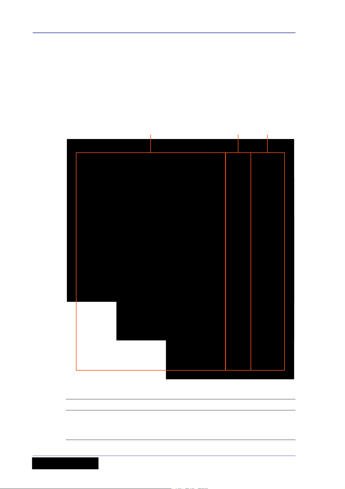
Control surface
The surface of the VeniceF can be divided into the following main vertical sections.
Control surfaces of the VeniceF consoles showing the three mains areas
Item Description
1 See Chapter 5 "Mono Input Channel" on page 31
2 See Chapter 6 "Dual Stereo Input Channel" on page 43
3 See Chapter 7 "Output Section" on page 53
Operator Manual
VeniceF
Page 13

Rear panel 5
710 8
6321
9
5
5
4 4
F32
F24
F16
Rear panel
The VeniceF has a rear panel that houses the following.
Rear panels of the VeniceF consoles showing the main areas
Item Description
1 See “Master outputs (mono and stereo)” on page 66.
2 See “Stereo returns” on page 63, “Groups” on page 57, “Matrices” on
page 61, “Monitors” on page 64 and “Auxes” on page 65.
3 See Chapter 6 "Dual Stereo Input Channel" on page 43.
4 See “Lamps” on page 71.
5 Ventilation grills. Do not obstruct.
6 See Chapter 5 "Mono Input Channel" on page 31.
7 See “FireWire” on page 35, page 46 and page 58.
8 See “Playback and recording” on page 69.
9 See “Local monitor and phones” on page 70.
10 See “Switching the VeniceF on/off” on page 16.
VeniceF
Operator Manual
Page 14
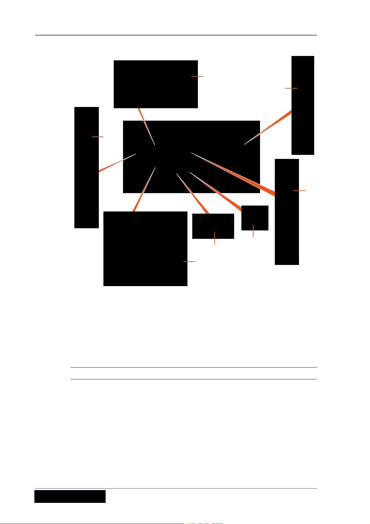
6 Chapter 1: Introduction
A
B
C
D
E
F
G
Rear panel of the VeniceF16 showing the main connector sections
A. Inserts and returns. B. Mono input channel (insert, direct out, line in and mic in).
C. Dual stereo channel (line in left and right, and mic inputs left and right). D. Playback
I/Os (left and right). E. Local monitor outputs. F. Aux, group, matrix and monitor
outputs. G. Stereo and mono master inserts and outputs.
External connections
The following table details all of the external connections on the VeniceF.
Connection(s) Description Notes
All mic inputs Balanced XLR connectors,
All primary line inputs Balanced Jacks 10K load Mono and stereo channels
All inserts Jack connectors, 50R
Mono and stereo channels
2K load
Mono and master
source, 10K load
channels
Group, matrix and
monitor buses
Stereo returns
VeniceF
Operator Manual
Page 15

Signal flow 7
Connection(s) Description Notes
All primary outputs Balanced XLR connectors,
50R source
All secondary outputs
(direct outs)
Headphone outputs Jack connectors, 10R
Playback left and right
inputs and outputs
FireWire connections FireWire (FW 4000 6-pin)
Power connections IEC mains inlet
Balanced Jack connectors,
50R source
source (nominal +10dB)
Unbalanced phono
connectors, 600R source
(nominal -10dB)
connector to IEEE1394
4-pin XLR lamp power
outlets
Master channels
Aux, group, matrix,
monitor and local
(monitor) buses
Tal k m i c i n talk mic
section of outputs (control
surface)
Mono channels
local monitor section of
outputs (control surface)
Rear panel
Rear panel
Rear panel
Under top edge of rear of
console
Signal flow
The following table gives an overview of the basic signal flow.
Channels or inputs Route to
8, 16 or 24 mono mic/line channels 2 monitor, 4 aux, 4 group and 3 master
4 stereo mic channels 2 monitor, 4 aux, 4 group and 3 master
4 stereo line inputs The same numbered stereo channel and
2 stereo return channels 2 monitor, group 1-2 (return 1) and
4 group channels 3 master and 2 matrix buses
3 master channels 2 matrix buses
4 aux channels N/A
2 monitor channels N/A
2 matrix channels N/A
buses, and FireWire (8, 16 or 24
channels)
buses, and FireWire (8 channels)
then onwards (as above) or the stereo
master bus
group 3-4 (return 2), and the stereo
master buses
All channel types can also access the PFL, and AFL (left and right) solo buses.
VeniceF
Operator Manual
Page 16

8 Chapter 1: Introduction
The following table shows the signal flow in detail.
Signal Sourced from Routed to
Mono Balanced XLR mic/line
input or balanced Jack line
Z input (common gain
control with above) or
FireWire connection or
insert return
Stereo Balanced XLR mic/line
input and balanced Jack
line Z input (independent
gain control) or FireWire
connection
Stereo return Balanced Jack Buses
Group Bus Master and matrix buses,
Aux Bus Insert Jack, monitor
Monitor Bus Insert Jack, monitor
Buses, insert Jack, direct
output Jack and FireWire
connection
Buses and FireWire
connection
insert Jack, group output
balanced XLR and optional
FireWire connection (in
place of stereo input
channel)
output balanced XLR and
optional FireWire
connection (in place of
stereo input channel)
output balanced XLR and
optional FireWire
connection (in place of
stereo input channel)
Matrix Insert Jack Insert Jack, matrix output
balanced XLR and optional
FireWire connection (in
place of stereo input
channel)
Stereo master bus Bus, input channels,
group buses, stereo
returns or playback
Mono master bus Bus, input channels,
group buses, stereo
returns or sum of stereo
bus
Insert Jack, master output
balanced XLR and optional
FireWire connection (in
place of stereo input
channel)
Insert Jack and master
output balanced XLR
Operator Manual
VeniceF
Page 17
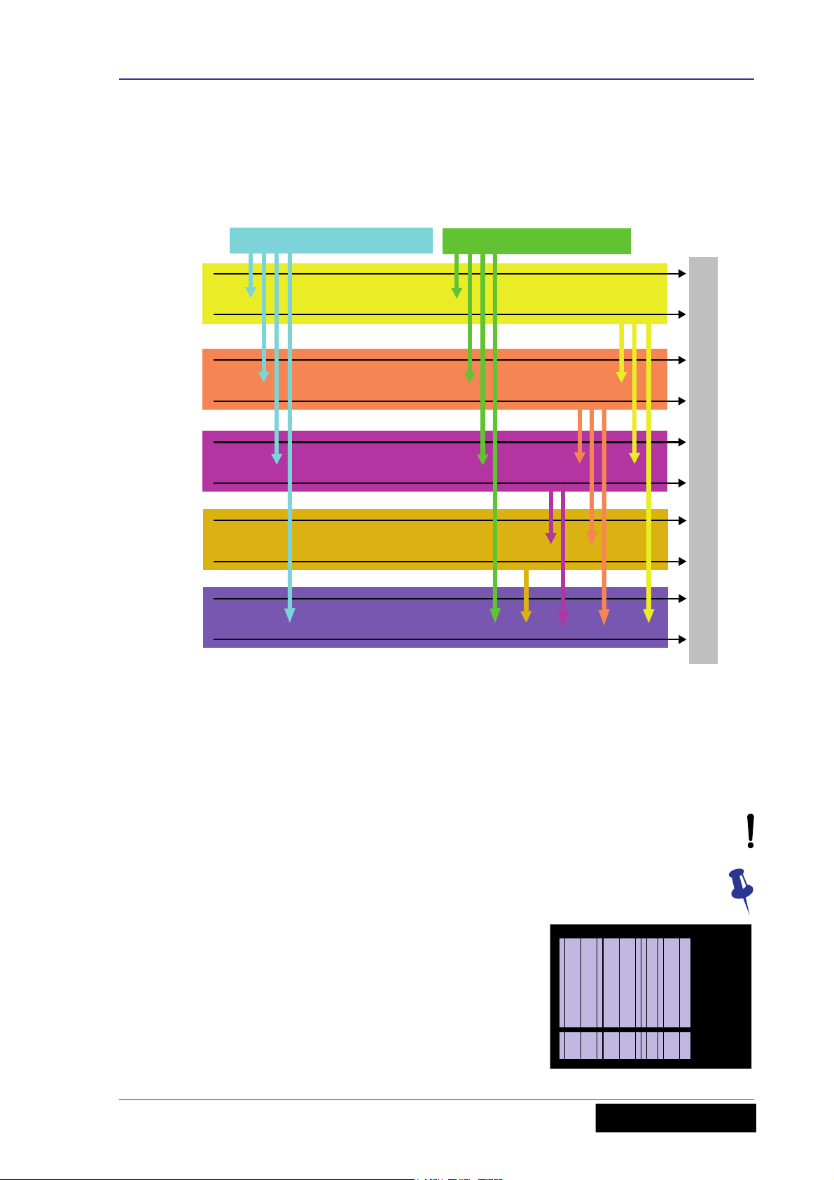
Mix matrix 9
6 aux buses
(include 2 monitors)
3 master (stereo
and mono) buses
4 group
buses
8/16/24 mic/line inputs 8 mic/line return inputs
2 matrix
buses
Bus outputs
3 solo
buses
Mix matrix
Ultimately, the mix matrix defines the capability of each VeniceF. It follows the console
layout, where inputs run vertically and buses run horizontally. A mix matrix is usually
defined as the number of buses and the quantity of simultaneously-mixable inputs
there are per bus.
VeniceF mix matrix
About this manual
This is the Operator Manual for the VeniceF. Its purpose is to familiarise the user with
the VeniceF and show how to install, set up, configure and operate the VeniceF.
This manual uses the following conventions:
• The exclamation mark (shown right) is intended to alert the user to important
operating instructions.
• The drawing pin (shown right) appears next to useful information, which
provides hints and tips.
• There are diagrams throughout the manual that
show you where on the console the local
information is referring to. These areas are
indicated by blue shading. For example, the mono
input channels, as shown right.
VeniceF
Operator Manual
Page 18

10 Chapter 1: Introduction
• Unless otherwise stated, an illuminated LED means that its related control/function
is on and when extinguished it is off.
• Although this manual is based on the VeniceF32 (pictures shown throughout), the
information also applies to the F16 and F24 models unless stated otherwise.
Trademarks
FireWire and the FireWire symbol are trademarks of Apple Inc., registered in the U.S.
and other countries. The FireWire logo is a trademark of Apple Inc.
Mac and the Mac logo are trademarks of Apple Inc., registered in the U.S. and other
countries.
Microsoft and Windows are registered trademarks of Microsoft Corporation in the United
States and other countries.
Service and support
We provide superb levels of support and service to give users confidence in Midas
products. For more information, please contact your local distributor or Midas at the
address shown in the front of this manual.
Operator Manual
VeniceF
Page 19

Chapter 2: Getting Started
This chapter shows you how to prepare the VeniceF for operation, which includes:
• Installation
• Connecting up
• Setting up
•Powering up
Before installing, setting up or operating this equipment make sure you have
read and fully understand all of the “IMPORTANT SAFETY INSTRUCTIONS” at
the front of this document and observe the following precautions.
Installation
11
The position of the console will vary from venue to venue. When installing the console,
take the following into consideration.
• Before installing and operating this Class 1 equipment, make sure it is correctly
connected to the protective earth conductor of the mains voltage supply socket
outlet through the mains lead.
• When positioning the console for FOH use it is worth placing the console in a position
where the sound system used can be heard properly from the mix position. Try to
avoid placing the console behind pillars or large objects, or mixing from a level
above the speaker position (for example, from a balcony).
• The console should be located in a convenient space commensurate with the use to
which the console is being put.
• Ideally a cool area is preferred, away from power distribution equipment or other
potential sources of interference.
• Do not install the equipment in places of poor ventilation.
• Do not install this equipment in a location subjected to excessive heat, dust or
mechanical vibration. Allow for adequate ventilation around the equipment, making
sure that its fans and vents are not obstructed. Whenever possible, keep the
equipment out of direct sunlight.
• Do not place the equipment in an unstable condition where it might accidentally fall
over.
• Provision should be made for some flat surface surrounding the console to prevent
people using it as a table top.
Handling the equipment
When lifting or moving the equipment, always take its size and weight into
consideration. If necessary, use suitable lifting equipment or transporting gear, or
sufficient additional personnel.
Completely isolate the equipment electrically and disconnect all cables from the
equipment before moving it.
Do not insert your fingers or hands in any gaps or openings on the equipment, for
example, vents.
VeniceF
Operator Manual
Page 20

12 Chapter 2: Getting Started
Radio frequency interference
This equipment has been tested and found to comply with the limits for a Class A digital
device, pursuant to Part 15 of the FCC Rules. These limits are designed to provide
reasonable protection against harmful interference when the equipment is operated in a
commercial environment. This equipment generates, uses, and can radiate radio
frequency energy and, if not installed and used in accordance with the instruction
manual, may cause harmful interference to radio communications. Operation of this
equipment in a residential area is likely to cause harmful interference in which case the
user will be required to correct the interference at his own expense.
Electric fields
In accordance with Part 15 of the FCC Rules & Regulations, “… changes or
modifications not expressly approved by the party responsible for compliance
could void the user's authority to operate the equipment.”
Should this product be used in an electromagnetic field that is amplitude modulated by
an audio frequency signal (20Hz to 20kHz), the signal to noise ratio may be degraded.
Degradation of up to 60dB at a frequency corresponding to the modulation signal may
be experienced under extreme conditions (3V/m, 90% modulation).
Operator Manual
VeniceF
Page 21
Connecting up 13
2
3
1
1
3
2
1
2
123
13
Connecting up
To ensure the correct and reliable operation of your equipment, only high quality,
balanced, screened, twisted pair audio cable should be used.
XLR connector shells should be of metal construction so that they provide a screen
when connected to the console and, where appropriate, they should have Pin 1
connected to the cable screen.
All Jack connector shells should be connected to the cable screen.
Audio connections
This section gives details of the audio connections of the VeniceF.
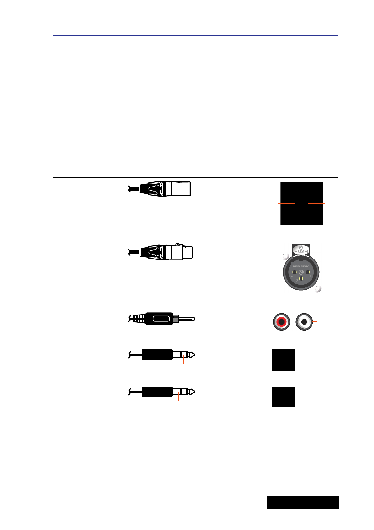
Table 1: Connector pinouts
Connector on rear
panel Example of plug Pinouts Example of socket
Male XLR chassis
connector (output)
Female XLR chassis
connector (mic input)
Pair of RCA
connectors (tape
in/out)
1/4” TRS Jack plug
(inserts)
1 = ground
2 = hot
3 = cold
1 = ground
2 = hot
3 = cold
1 = ground
2 = signal
1 (tip) = send
2 (ring) = return
3 (sleeve) =
ground
1/4” TRS Jack plug
(input, output)
VeniceF
Operator Manual
1 (tip) = hot
2 (ring) = cold
3 (sleeve) =
ground
Page 22
14 Chapter 2: Getting Started
3
Female XLR
Male XLR
3
2
1
2
1
Sleeve
Ring
Tip
Male XLR
Tip
Sleeve
Ring
Female XLR
Input and output
sockets on rear of
external device
Rear of VeniceF console
1/4” TRS Jack
Screen
Send
Return
Send
Return
Tip
Sleeve
Ring
Sockets on
rear of
external
device
Rear of VeniceF console
Sleeve
Ring
Tip
1/4” TRS Jack
Sleeve
Tip
Input
Output
Sleeve
Tip
Screen
Input
Output
1/4” TS Jack
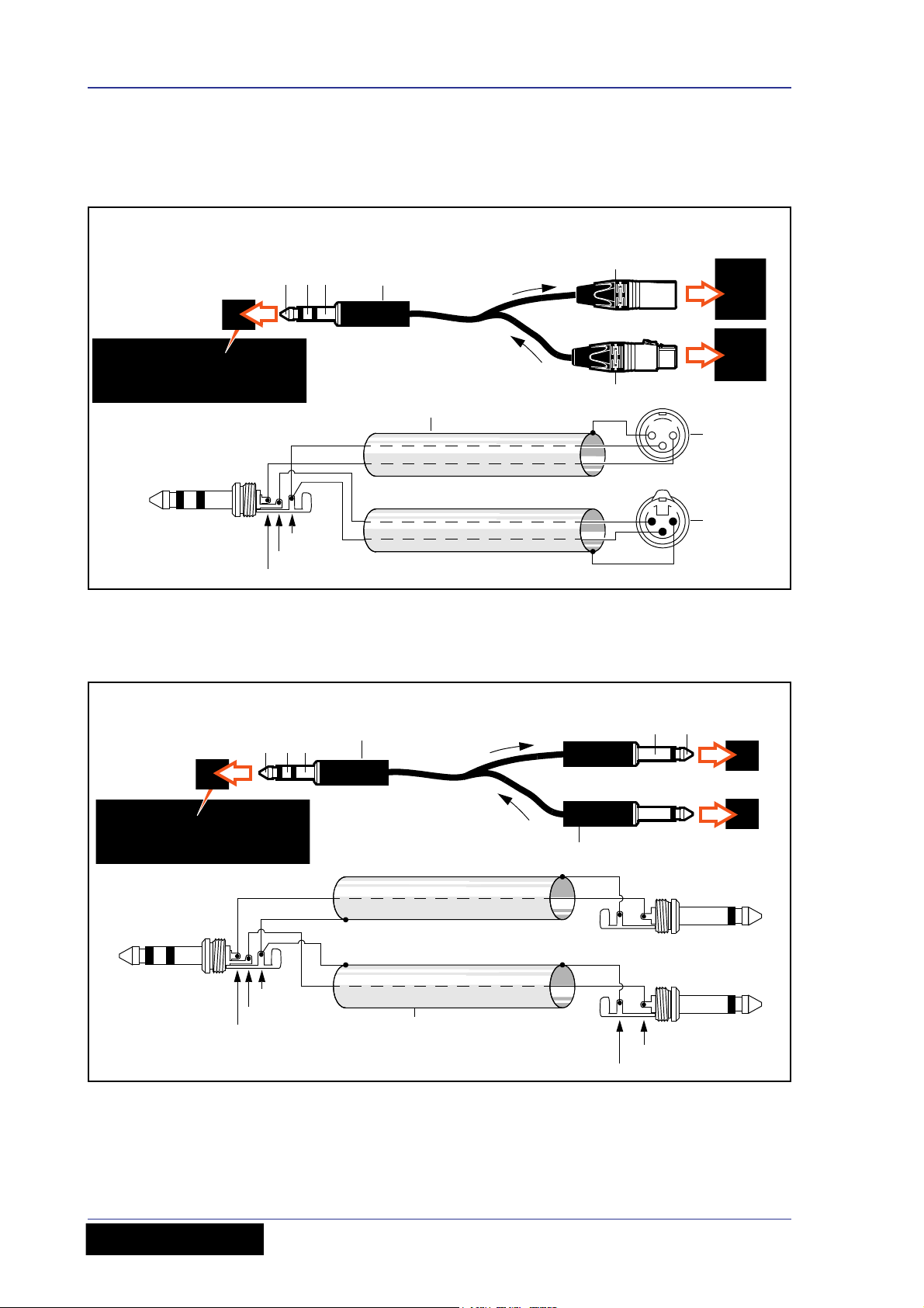
Connecting to balanced/unbalanced equipment
The inserts of the VeniceF are unbalanced. Ideally, you will be connecting the inserts to
balanced equipment to help avoid noise problems due to grounding.
Figure 1: Connecting to balanced equipment
However, if you do have to connect to unbalanced devices, the following wiring is
recommended for best results.
Figure 2: Connecting to unbalanced equipment
Important:
If you have any audio problems, see Appendix E "Best Grounding Practice" on
page 101.
Operator Manual
VeniceF
Page 23
Connecting up 15
4
1
3
2
123
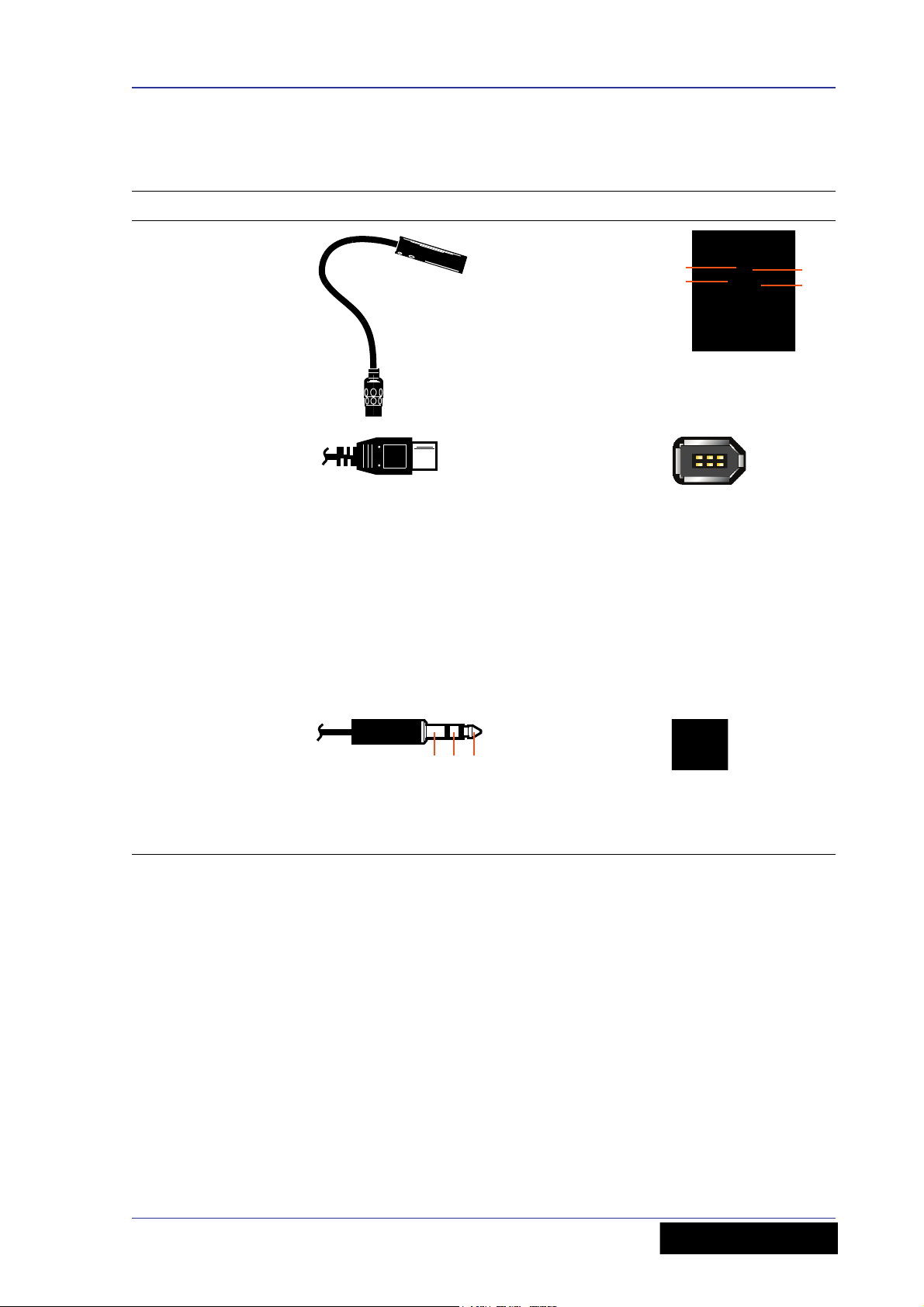
Other connections
The section gives details of the other VeniceF interconnections.
Description Example Pinouts Example of socket
4-pin, male XLR
chassis connector(s)
on the rear panel for
connecting 12V/5W
lamp(s)
1-off socket in the
FireWire section of
the rear panel for
connecting a 6-pin,
FireWire 400
connector
Important:
If you have any
audio problems
these may be due
to ground loops
(see Appendix
E "Best Grounding
Practice" on
page 101).
1 = N/A
2 = N/A
3 = ground
4 = 12V
N/A
Headphones socket in
the local monitor
section of the control
surface for connecting
a 1/4” TRS Jack plug.
There is also one
under the armrest on
the desktop versions.
1 (tip) = left
2 (ring) = right
3 (sleeve) =
ground
VeniceF
Operator Manual
Page 24
16 Chapter 2: Getting Started
A
B
Setting up
There is no initial setting up required for the VeniceF console. However, if you want to
use FireWire, you will need to set up you PC first (see Chapter 3 "Using The VeniceF
With FireWire" on page 17).
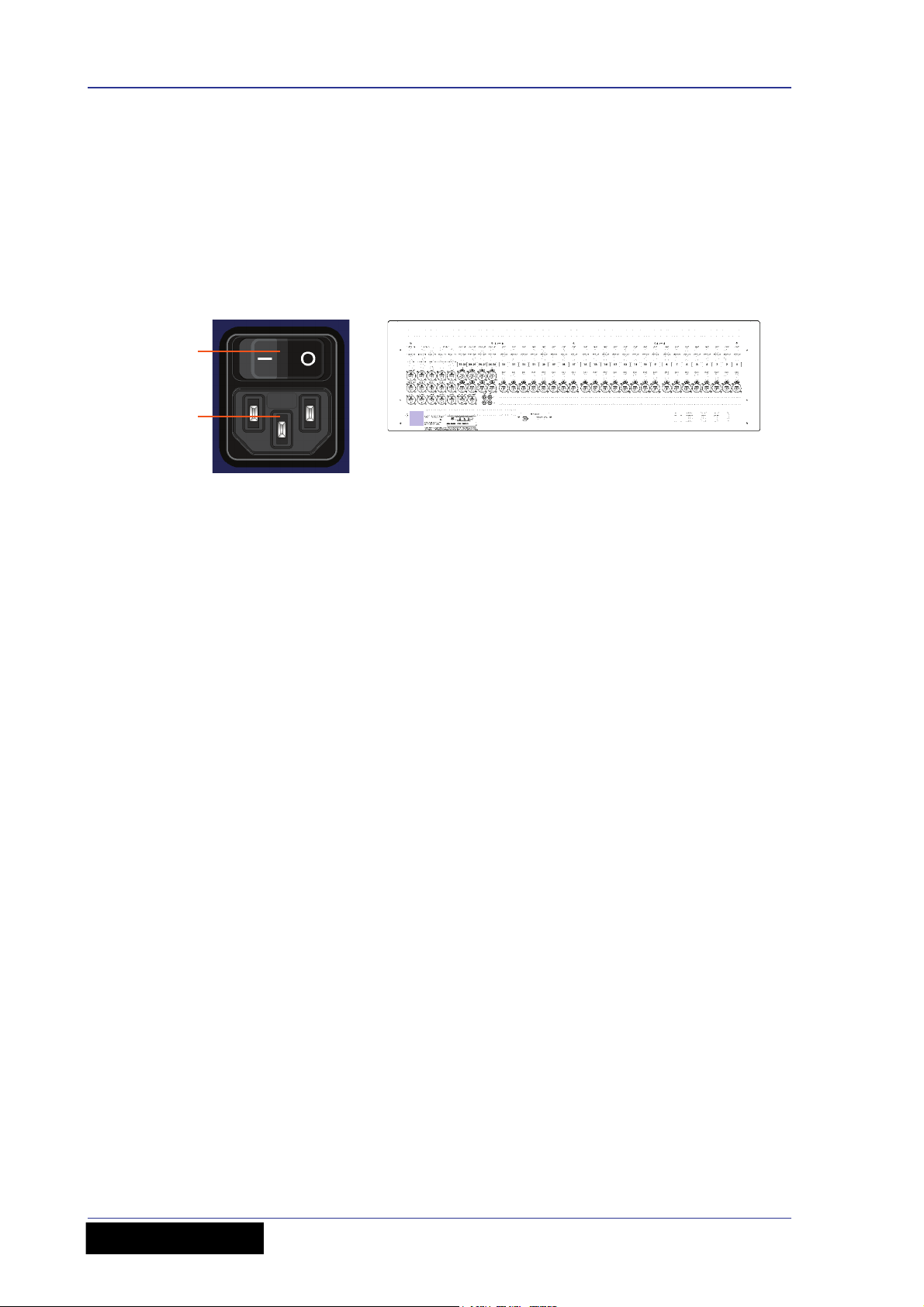
Switching the VeniceF on/off
Switch the VeniceF on/off via the mains switch on the rear panel.
Mains power supply input on the rear panel. A. Mains on/off switch. B. Mains power
supply socket (IEC connector).
Operator Manual
VeniceF
Page 25

Chapter 3: Using The VeniceF With FireWire
This chapter shows you how to prepare your PC/Mac for using FireWire, how to update
the FireWire driver and how to troubleshoot FireWire. For information on how to use
FireWire with the ‘bundled’ recording software, refer to the Software Application Guide.
Installing FireWire on a PC
This section shows how to install and set up FireWire on a PC running the Windows®
operating system. This procedure comprises three main steps:
• “Step A — Installing the device driver on your PC”
• “Step B — Connecting the VeniceF to your PC”
17
• “Step C — Configuring the FireWire settings for the VeniceF”
Step A — Installing the device driver on your PC
Do not connect the FireWire cable to the PC before installing the device
driver.
Important:
Before installing the FireWire device driver from the VeniceF USB memory
stick, we recommend that you make sure it is the latest version by checking
the www.midasconsoles.com website. This is important, as you may not be
able to use FireWire properly with an older version of the device driver.
>> To install the FireWire device driver
1 The FireWire device driver software is on the VeniceF USB memory stick. Plug
the VeniceF USB memory stick into your PC. (Depending on your PC’s
configuration, a window may open asking you what you want Windows to do. If
so, select the Open folder to view files option and then click OK.)
2 On the USB memory stick, double-click the “MidasFW-Installer.exe” file to start
the setup wizard.
3 In the Setup - Midas FW window
(right), click Next.
VeniceF
Operator Manual
Page 26
18 Chapter 3: Using The VeniceF With FireWire
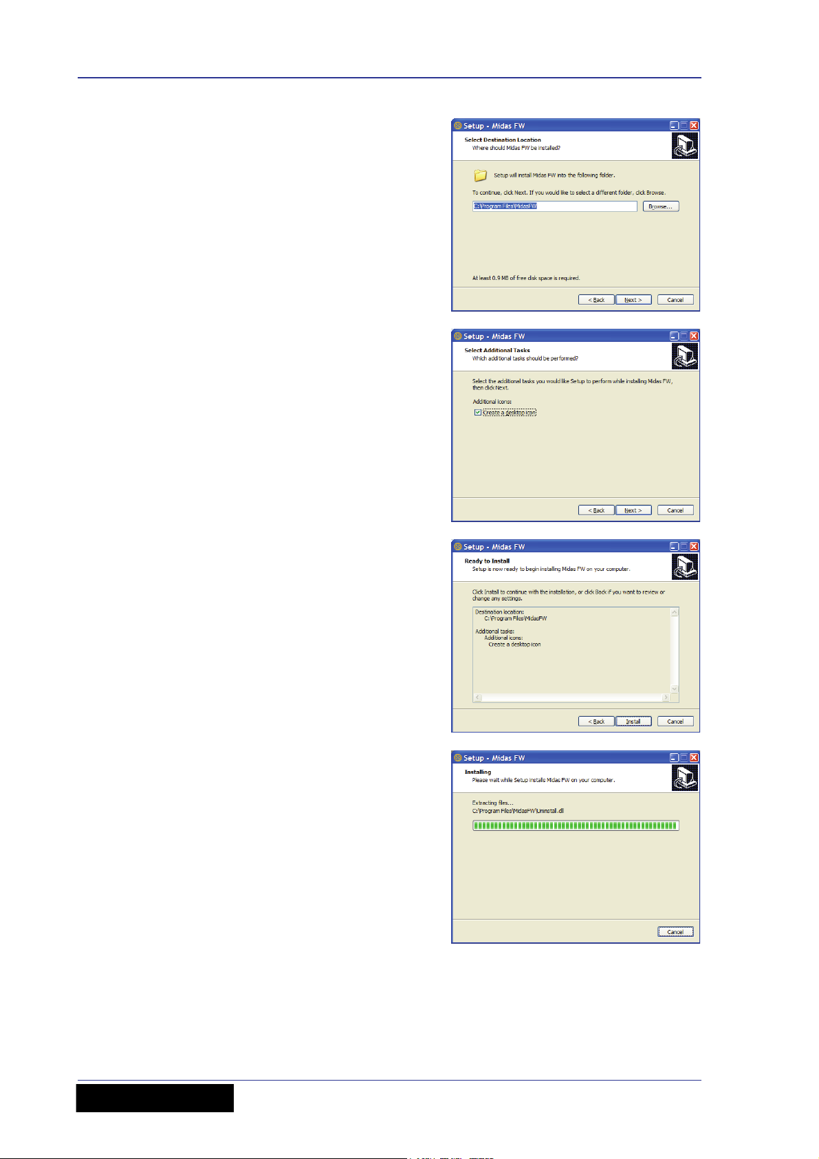
4 In the Select Destination Location
window, click Next.
You can change the install location by
typing it in or using the browse facility.
5 In the Select Additional Tasks
window, click Next.
You can choose to create a desktop
icon by selecting the Create a
desktop icon option.
6 If the installer’s release notes appear,
close them. Then, in the Ready to
Install window, check that the
information is correct and click Install.
7 The Installing window will display the
progress of the installation.
Operator Manual
VeniceF
Page 27

Installing FireWire on a PC 19
8 If the Windows “Logo testing”
compatibility window appears, click
Continue Anyway.
9 To complete the installation, select the
Yes, restart the computer now
option and then click Finish.
You must restart your PC before using the VeniceF driver you have just
installed.
After restarting your PC, proceed to the next step (see “Step B — Connecting the
VeniceF to your PC” on page 20).
VeniceF
Operator Manual
Page 28
20 Chapter 3: Using The VeniceF With FireWire
6-pin (VeniceF)
9-pin
4-pin
Step B — Connecting the VeniceF to your PC
Important:
The VeniceF must be switched on before the FireWire cable is connected to it.
When you use your PC with the VeniceF for the first time after installing the FireWire
device driver, you will need to install the VeniceF device software. This is so that your
PC will recognise the VeniceF whenever they are connected together.
>> To connect the PC to the console
Do not attempt the following procedure until you have completed Step A
(see “Step A — Installing the device driver on your PC” on page 17).
1 Switch on the VeniceF.
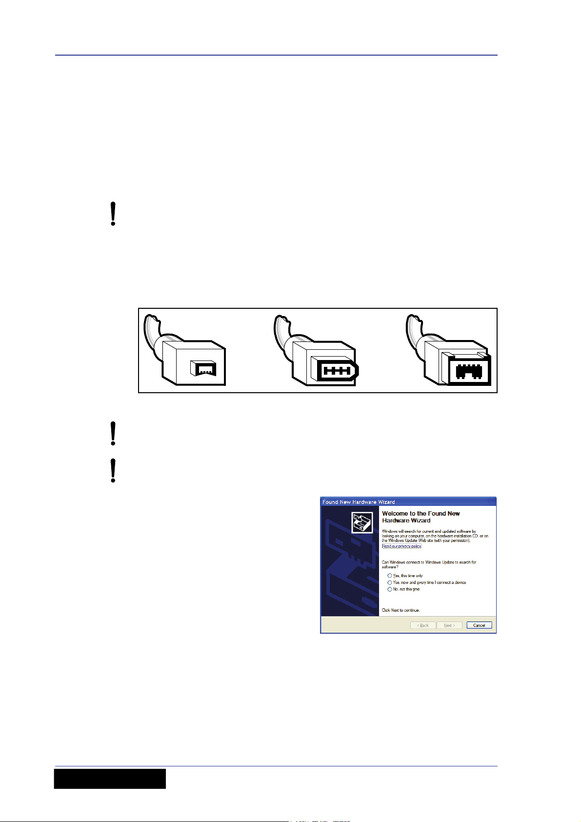
2 Connect the VeniceF to the PC using the appropriate FireWire cable, while
observing the following precautions. Plug the 6-pin connector into the FireWire
socket of the FireWire section on the rear of the console. Connect the other end
of the cable into the PC.
Figure 3: Some typical FireWire connectors
Make sure you use the correct FireWire cable connector with your PC.
When plugging the FireWire connector into your PC, make sure the
connector is the correct way up and take great care not to exert too much
force.
3 In the Found New Hardware Wizard
window, select the No, not this time
option and then click Next.
VeniceF
Operator Manual
Page 29
Installing FireWire on a PC 21
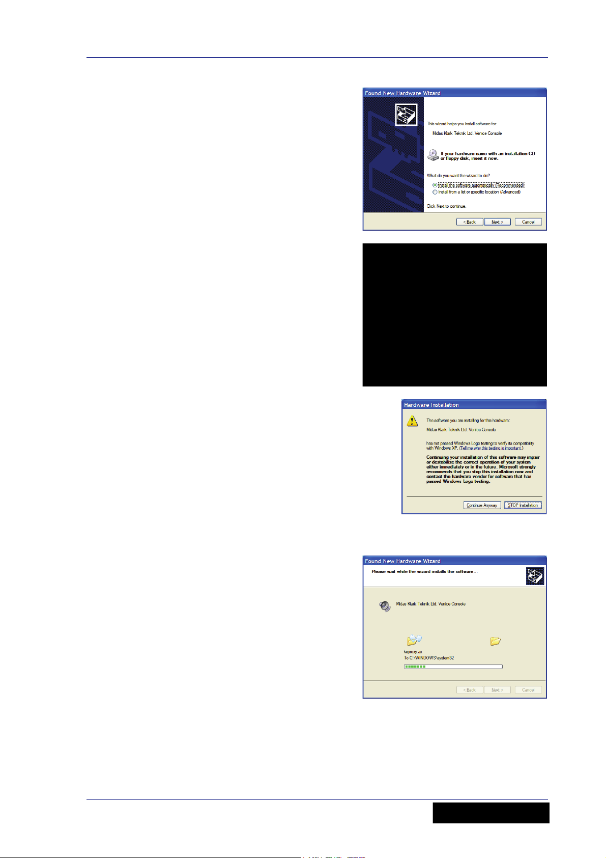
4 For standard installation, select the
Install the software automatically
(Recommended) option and then
click Next.
5 The wizard will perform a search for
the correct driver. When it has
finished, click Next.
6 When the Windows “Logo testing”
compatibility window appears, click
Continue Anyway.
7 The driver will now be installed.
VeniceF
Operator Manual
Page 30
22 Chapter 3: Using The VeniceF With FireWire
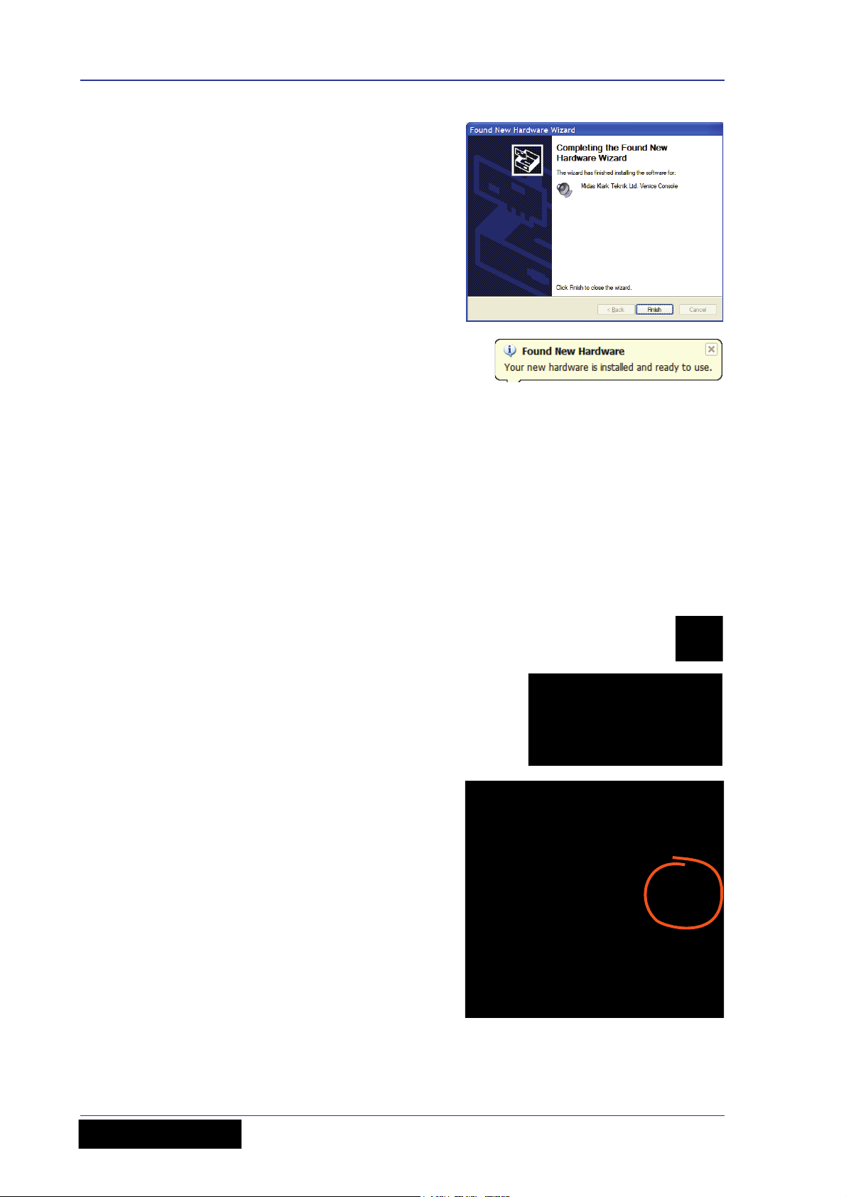
8 After the wizard has finished installing
the driver, click Finish.
After the device hardware has been
successfully installed, you will see a Found
New Hardware balloon on your desktop.
You are now ready to configure the VeniceF FireWire settings (see Step C below).
Step C — Configuring the FireWire settings for the VeniceF
In general, you should be able to use your recording software application on your
PC/Mac quite successfully using the default FireWire settings. However, you can
change the settings, if desired (for example, if you have audio problems), which is done
in the Midas FW FireWire settings window.
Configuration of the VeniceF’s FireWire settings involves opening the Midas FW
settings window, selecting your desired options and then closing the window.
>> To open the Midas FW settings window
1 On your PC/Mac desktop, double-click
the Midas FW icon.
2 If no devices are found, you will see
the message shown right. Make sure
the PC/Mac and console are properly
connected together with the FireWire
cable, and then click ok.
3 The Midas FW settings window will
open. In the Devices section you
should see the Venice icon (shown
right).
Operator Manual
VeniceF
Page 31

Installing FireWire on a PC 23
5
1 32 4
6
7
8
91011
>> To change the FireWire settings
Use the drop-down lists and buttons on the Midas FW settings screen to change the
FireWire settings, as desired, using the following diagram and the accompanying list of
associated elements to guide you.
Note: The settings available for configuration may be dependent on a number of
variables, such as the hardware specification of the PC, the type of operating system
you are using, the recording software application, etc. The setting you may want to
adjust may be available for change in the recording software application itself.
Mains elements of a typical Midas FW screen (PC version)
Item Element Description
1 WDM button
The WDM
1
button lets you select a different audio
device driver, such as Sonar.
2 Sample Rate
drop-down list
This drop-down list lets you select the sample rate
(samples per second) for the VeniceF. Options are
44.1kHz and 48kHz.
3 Info button Use this button to check the software version of the
driver.
4 Master drop-down
list
This drop-down list shows the clock source. (This will
be always be set to Venice.)
VeniceF
Operator Manual
Page 32

24 Chapter 3: Using The VeniceF With FireWire
Item Element Description
5 Buffer Size
drop-down list
6 Operation Mode
drop-down list
7 Venice icon This icon shows you that the PC/Mac recognises the
8 Devices panel This panel shows you what FireWire device(s) are
9 Device
description field
10 Nickname field This field gives a shortened description of the
11 Measured
Sampling Rate
field
This drop-down list lets you select the buffer size that
the PC/Mac will use for the recording software.
Select buffer size according to your equipment,
remembering that if it is too small you will
suffer audio clicks and pops, and if it is too
large there will be audible delays (latency).
This drop-down list lets you select another operating
mode if you are having problems with the audio.
(Default = normal.)
connected device as a VeniceF and that the
connection is good.
connected to your PC/Mac. If the message “no
devices found” appears in this panel, see “No devices
found” on page 28.
This field gives details of the selected device.
selected device.
This field shows the sampling rate of the currently
connected device.
1. Windows Driver Models (WDMs) are audio device drivers for the Microsoft® Windows®
family of operating systems.
>> To select an option from a drop-down list
Click the up/down arrow box of the drop-down list to open it,
and then click the desired option.
>> To close the Midas FW window
Click “X” at the upper-right corner of the Midas FW window.
Operator Manual
VeniceF
Page 33

Installing FireWire on a Mac 25
Installing FireWire on a Mac
This section shows how to install and set up FireWire on a Mac. This procedure
comprises the following main steps:
• “Step A — Installing the device driver on your Mac”
• “Step B — Connecting the VeniceF to your Mac”
• “Step C — Configuring the FireWire settings for the VeniceF”
Step A — Installing the device driver on your Mac
Do not connect the FireWire cable to the Mac before installing the device
driver.
Important:
Before installing the FireWire device driver from the VeniceF USB memory
stick, we recommend that you make sure it is the latest version by checking
the www.midasconsoles.com website. This is important, as you may not be
able to use FireWire properly with an older version of the device driver.
>> To install the FireWire device driver
1 The FireWire device driver software is on the VeniceF USB memory stick. Plug
the VeniceF USB memory stick into your Mac.
2 On your Mac, locate the “MidasFW-
x.x.x-xxxx-osx” folder on the USB
memory stick — which should be in the
“Driver” folder — and double-click it to
open it.
3 In the“MidasFW-x.x.x-xxxx-osx” folder,
double-click the “MidasFW.dmg” file.
4 In the disk image file window,
double-click the “MidasFWx.x.x.xxxx.pkg” package file to start
the Midas FW driver installer.
VeniceF
Operator Manual
Page 34

26 Chapter 3: Using The VeniceF With FireWire
5 At the Introduction stage of the
installation procedure, observe the
driver release notes and then click
Continue.
6 If your Mac has another hard drive
connected, the Destination Select
stage will let you select another install
location. Otherwise, go to the next
step.
7 At the Installation Type stage, click
Install. (If a password window
appears, enter your password and
continue.)
8 At the Installation stage, click
Continue. Your Mac will start
installing the driver.
9 After the driver has been installed
successfully, your Mac will display the
window shown right at the Summary
stage. Click Restart.
Your Mac will reboot automatically. After it
has restarted it is ready to use.
You must make sure that you Mac has restarted before using the VeniceF
driver you have just installed.
Operator Manual
VeniceF
Page 35

Updating the FireWire driver 27
Step B — Connecting the VeniceF to your Mac
Important:
The VeniceF must be switched on before the FireWire cable is connected to it.
>> To connect the Mac to the console
Do not attempt the following procedure until you have completed Step A
(see “Step A — Installing the device driver on your Mac” on page 25).
1 Switch on the VeniceF.
2 Connect the VeniceF to the Mac using the appropriate FireWire cable (see
Figure 3 “Some typical FireWire connectors” on page 20), while observing the
following precautions
Make sure you use the correct FireWire cable connector with your Mac.
When plugging the FireWire connector into your Mac, make sure the
connector is the correct way up and take great care not to exert too much
force.
Step C — Configuring the FireWire settings for the VeniceF
In general, you should be able to use your recording software application quite
successfully using the default FireWire settings. However, you can change the settings
if you want (for example, if you have audio problems) in the Midas FW FireWire
settings window. For details of how to configure the VeniceF’s FireWire settings, see
“Step C — Configuring the FireWire settings for the VeniceF” on page 22.
Updating the FireWire driver
The latest version of the FireWire driver for the VeniceF will be available on the Midas
website (address is on the front cover of this manual).
>> To update your PC/Mac with the latest driver
1 Download the latest VeniceF FireWire driver from the Midas website onto your
PC/Mac. There should be two drivers available — one each for a PC and Mac — so
make sure you download the correct one.
2 Install the latest VeniceF FireWire driver (see “Installing FireWire on a PC” on
page 17 or “Installing FireWire on a Mac” on page 25). You don’t have to
uninstall the existing VeniceF FireWire driver, as this it will be overwritten by the
new one.
VeniceF
Operator Manual
Page 36

28 Chapter 3: Using The VeniceF With FireWire
Troubleshooting FireWire
The following subsections may help you overcome any problems that may arise when
using FireWire.
Audio problems
If you encounter any problems with the audio, for example, when recording, try
changing the FireWire settings (see “Step C — Configuring the FireWire settings for the
VeniceF” on page 22).
No devices found
Important:
The VeniceF must be switched on before the FireWire cable is connected to it.
If you see a ‘no devices found’ message, it means that the PC cannot detect a FireWire
device. To clear the message, do one of the following:
• Connect the VeniceF to the PC.
•If the VeniceF is already connected to the PC, check that the connections are good.
Overcoming ground loop problems
See Appendix E "Best Grounding Practice" on page 101.
Operator Manual
VeniceF
Page 37

Chapter 4: Working With The Console
The following chapters give a description of the controls on the console surface and
include useful operating information.
• Chapter 5 "Mono Input Channel" on page 31
• Chapter 6 "Dual Stereo Input Channel" on page 43
• Chapter 7 "Output Section" on page 53
Before using FireWire, read Chapter 3 “Using The VeniceF With FireWire”.
Ground loop problems
In the event of ground loop problems, disconnect the signal screen at one end of the
connecting cables. Note that this can only be done when the equipment is used with
balanced cable systems. For more information, see Appendix E "Best Grounding
Practice" on page 101.
29
VeniceF
Operator Manual
Page 38

30 Chapter 4: Working With The Console
Operator Manual
VeniceF
Page 39

Chapter 5: Mono Input Channel
This chapter details the mono input channels (8/16/24) of the VeniceF. It describes the
sections of each channel on the control surface and the related connectors on the rear
panel.
31
Mono input channels on the control surface (F32 shown)
Although the actual number of mono input channels on your VeniceF will depend upon
your choice of frame, their function remains the same.
VeniceF
Operator Manual
Page 40

32 Chapter 5: Mono Input Channel
1
3
4
5
6
2
Overview of the mono input channel
Each mono channel has an XLR input that can be used for mic or line
level signals up to +32dBu. An additional 1/4” inch TRS Jack socket,
provides an input for line level signals that require protection against
accidental 48-volt connection. The line input gives 10dB of permanent
attenuation to the input signal, which allows the connection of extremely
high line level signals of up to +42dBu with the pad engaged.
Item Section
1 Gain (see “Gain” on page 34)
2 FireWire and direct output section (see “FireWire” on
page 35)
3 Insert and EQ (see “Insert” on page 35 and “EQ” on page 36)
4 Monitor and aux contributions (see “Monitors” on page 37
and “Auxes” on page 38)
5 Pan and routing (see “Pan, routing, mute and solo” on
page 39)
6 100 mm fader and meter (see “Fader and meter” on page 41)
Operator Manual
VeniceF
Page 41

Rear panel 33
1
2
3
4
Rear panel
The VeniceF channel inputs are located on the rear panel of the console and each
channel comprises the following.
Mono input channel connectors
Item Description
1 insert connector Insert point on a single 1/4” TRS Jack socket. This is
unbalanced and requires a conventionally-wired insert lead.
2 direct out connector Direct output on a single, balanced 1/4” TRS Jack
socket.
3 line in connector Line in on a single, balanced 1/4” TRS Jack socket.
4 mic connector Mic input on a single, balanced XLR female chassis
connector.
The direct out and insert points operate at a nominal level of 0dBu.
Balanced XLR and Jack inputs are conventionally wired (see Table 1 “Connector
pinouts” on page 13).
VeniceF
Operator Manual
Page 42

34 Chapter 5: Mono Input Channel
1
2
34
5
Gain
This section lets you adjust the level of the mic input signal, switch on 48 volts phantom
power for the mic, attenuate the input signal by 20dB, invert the mic polarity and
enable the high pass filter on the mic input.
Mic gain section of the mono input channels
Item Description
1 20dB pad switch This pad switch provides 20dB attenuation to the input
signal, allowing for the connection of high output microphones and line level
signals without overloading the channel input amplifier. Overloads are
indicated on the meter by the red LED at the top (see “Fader and meter” on
page 41).
2 mic gain control knob The mic gain is continuously variable from +10dB
to +60dB (-10dB to +40dB with the pad enabled). The actual value of the
gain required will depend upon the source and should ideally be set such
that peaks in level on the input should not cause the input amplifier to
overload (occasional peaks of +12dB are OK, but +18dB is too high).
3 80Hz switch The hi pass switch inserts the 80Hz hi pass filter in the input
channel signal path before the insert point and EQ. This is commonly used
to remove handling noise from a mic, bass rumble through coupling with
the stage or any unwanted low frequency audio.
4 mic Ø switch This is a microphone polarity switch that causes a
180-degree phase change (with respect to the input signal) to occur in the
input amplifier such that the channel signal will have opposite polarity to
the input signal.
The mic Ø switch is commonly needed where two microphones are used
facing each other (for example, when using a microphone on both the top
and bottom of a snare drum). Ordinarily the two microphones would be out
of phase causing cancellation when the console sums the two signals into
the output. Reversing the phase of one signal causes the microphones to
have the same phase and no cancellation.
5 48V LED and power switch The power switch applies 48 volts of
phantom power to the microphone input. This is used to power condenser
microphones, direct inject boxes and other devices that require phantom
power. The 48V LED illuminates to show that phantom power is on.
VeniceF
Operator Manual
Page 43

FireWire 35
1
2
FireWire
This section lets you select the channel input source as mic/line (analogue) or FireWire
(digital) and select the FireWire output signal as pre-EQ or post-EQ. For more
information on FireWire, see Chapter 3 "Using The VeniceF With FireWire" on page 17.
FireWire section of the mono input channels
Item Description
1 input switch and green LED The green FireWire input switch breaks the
mic and line signals, making the channel input FireWire only and,
effectively, creating a FireWire insert point (when combined with the
FireWire direct output). The green LED illuminates to show when the switch
is on.
Insert
Important:
To avoid a feedback loop, take care not to switch FireWire sends to
post-EQ when using FireWire inputs as digital insert returns.
2 firewire & direct out switch Switches the signal, which is routed to the
FireWire output and direct out, to pre-EQ (button out) or post-EQ (button
in).
This insert switch enables the channel’s analogue insert point, by connecting the insert
return to the channel signal path. This lets you use traditional compressor, gates or
other dynamic and signal processors or effects with the console. The yellow LED
illuminates to show when the insert is enabled.
Insert section of the mono input channels
VeniceF
Operator Manual
Page 44

36 Chapter 5: Mono Input Channel
1
2
3
4
5
6
7
EQ
Each mono input channel of the VeniceF has a four-band, swept EQ, allowing tonal
control over the input signal.
EQ section of the mono input channels
Item Description
1 Treble gain/freq control knob This dual-concentric control knob adjusts
the gain/frequency of the treble EQ:
• gain The top control knob adjusts the gain of the treble band, which is
continuously variable from -15dB to +15dB with a centre detent of 0dB.
• freq The bottom control knob adjusts the centre frequency of the treble
band, which is continuously variable from 2kHz to 20kHz.
2 Hi mid gain/freq control knob This dual-concentric control knob adjusts
the gain/frequency of the hi mid EQ:
• gain The top control knob adjusts the gain of the hi mid band, which is
continuously variable from -15dB to +15dB with a centre detent of 0dB.
• freq The bottom control knob adjusts the centre frequency of the
hi mid band, which is continuously variable from 400Hz to 8kHz.
3 Hi mid width control knob This hi mid control knob adjusts the filter
bandwidth.
4 Lo mid width control knob This lo mid control knob adjusts the filter
bandwidth.
Operator Manual
VeniceF
Page 45

Monitors 37
1
2
Item Description
5 Lo mid gain/freq control knob This dual-concentric control knob
adjusts the gain/frequency of the lo mid EQ:
• gain The top control knob adjusts the gain of the lo mid band, which is
continuously variable from -15dB to +15dB with a centre detent of 0dB.
• freq The bottom control knob adjusts the centre frequency of the
lo mid band, which is continuously variable from 100Hz to 2kHz.
6 Bass gain/freq control knob This dual-concentric control knob adjusts
the gain/frequency of the bass EQ:
• gain The top control knob adjusts the gain of the bass band, which is
continuously variable from -15dB to +15dB with a centre detent of 0dB.
• freq The bottom control knob adjusts the centre frequency of the bass
band, which is continuously variable from 20Hz to 200Hz.
7 EQ switch and red LED The EQ switch enables the EQ. With EQ disabled,
adjustment of the EQ controls has no effect. This can be used to compare
the sound with and without EQ. The red LED illuminates to show that EQ is
enabled.
Monitors
The two monitor sends per input channel have the same functionality as the auxes (see
“Auxes” on page 38). However, they have the following additional features:
• They can be sourced pre-EQ.
• They can be metered individually (see “Monitors” on page 64).
• They can receive a contribution from the stereo returns (see “Stereo returns” on
• They have individual talk buttons (see “Signal generator and talkback” on page 68).
Monitor section of the mono input channels
page 63).
Item Description
1 Monitor control knob The monitor control knobs give continuous
adjustment of the signal sent from the input channel to the monitor buses
(default is post-fader and post-EQ) in the range
4 (infinity/off) to +6dB.
Either monitor send can be sourced pre-fader globally using the pre switch in the
output section (see “Monitors” on page 64).
VeniceF
Operator Manual
2 pre eq switch Changes the source of the monitor sends to pre-EQ,
provided the bus is set to be pre-fader via the pre switch in the output
section (see “Monitors” on page 64).
Page 46

38 Chapter 5: Mono Input Channel
Auxes
The VeniceF has four aux sends per input channel, which can be used for effects sends,
monitors or as extra assignable outputs from the console. Each aux has a control knob
that gives continuous adjustment of the level sent from the input channel to the aux
buses, in the range 4 (infinity/off) to +6dB.
Aux sections of the mono input channels
Auxes are post-EQ and post-fader, but each of the four aux buses can be independently
switched globally to pre-fader using the pre switch in the outputs section (see “Auxes”
on page 65).
• Post-fade aux sends are sourced after the channel insert, mute, EQ and channel
fader. As a result, the actual level sent to the aux bus is proportional to the aux
send control and the channel fader.
• Pre-fade aux sends are sourced after the channel insert, mute and EQ, but before
the channel fader. As a result, the actual level sent to the aux bus is proportional to
the aux send control only.
The following table shows some typical uses for auxes.
Application Pre-/Post-fade Reason
Stage monitors Pre-fade (post-EQ) The level in the monitor stays constant,
so that the engineer can change the FOH
fader level without affecting the
performer.
Effect sends Post-fade (post-EQ) The level sent to the effects is
proportional to the level on the fader, so
the balance between wet (processed)
and dry (unprocessed) sound stays the
same, even when the channel level is
changed.
Mixed recording Post-fade (post-EQ) If the aux is set to unity the FOH mix is
replicated on the aux output. This
includes EQ, but excludes pan.
Operator Manual
VeniceF
Page 47

Pan, routing, mute and solo 39
3
4
6
5
2
1
7
Pan, routing, mute and solo
The VeniceF is a flexible mixing console with four group buses plus stereo and mono.
Groups and solo sections of the mono input channels
Item Description
1 Group switches Each group switch routes the channel signal to its
associated group bus (as described later in this section).
2 mono switch This switch routes the channel signal to the mono bus
(post-EQ, post-mute and post-fader).
3 stereo switch Routes the channel signal to the stereo master bus
(post-EQ, post-pan, post-mute and post-fader).
4 pan control knob The pan control allows the channel signal to be
positioned in a stereo field when routed to the stereo bus, or when group
sends are configured to be stereo. The pan control allows continuous
adjustment of the image from hard left, to hard right with a centre detent,
and obeys a constant power law (that is, -3dB at the centre).
5 pan to groups switch The VeniceF’s group sends may be configured by
pressing this switch for stereo group operation or released for mono group
mode (as described later in this section).
6 MUTE switch and red LED The MUTE switch mutes the channel signal.
The signal will still be sent to the insert point and to the direct
output. The mute LED illuminates to show that the MUTE switch is on.
7 SOLO switch and yellow LED With solo enabled the channel signal is
sent to the after-fade listen (AFL) stereo and pre-fade listen (PFL) mono
buses. The left and right local monitor outputs can be used, for example,
when operating from within a booth to hear selected solos and not the
whole mix. The solo LED illuminates to show when a solo is on.
The signal can be routed to any of the four group buses by pressing the corresponding
group select switch.
VeniceF
Operator Manual
Page 48

40 Chapter 5: Mono Input Channel
Group routing, which is post-EQ, post-mute and post-fader, can be configured in either
of two modes:
• Pre-pan (mono) Each group is sent the same mono signal, so that, for example,
selecting 1, 2 and 3 will send to each group equally.
• Post-Pan (stereo) Each pair of groups behave as if they were stereo groups. The
mono signal is positioned in a stereo field by the pan control. The left signal is
routed to the odd numbered bus and the right signal to the even numbered bus.
Selecting groups 1, 2 and 3 with pan hard left will result in the signal being routed to
groups 1 and 3 only. Similarly, with pan hard right, the signal will be sent only to
group 2.
This configuration is made by pressing the pan to groups button for stereo group
operation or released for mono group mode.
This selection, however, is on a channel-by-channel basis and so some may be assigned
to the groups as mono or as stereo, depending upon the desired usage. For example:
Application Configuration Reason
Submix Stereo Submix of drum kit.
Submix Mono Vocals with inserted compressor
(multiple vocals feed the same
compressor).
Operator Manual
VeniceF
Page 49

Fader and meter 41
1
2
Fader and meter
The VeniceF has a 100 mm fader and a four-LED signal meter per mono input channel.
Fader section of the mono input channels
Item Description
1 LED meter These four LEDs comprise the input channel meter, which lets
you monitor the input signal without having to use the PFL. The red +18
LED will also show any overload activity on the FireWire and direct output.
2 Fader This channel fader allows for continuous adjustment of the channel
level from
stereo, mono and group buses will be at unity, that is, no adjustment in
level from the input.
The meter is especially useful when setting the microphone gain of a channel. Also, as
the meter is post-EQ, it is possible to see the effect that the channel equalisation has
upon the level. It may be necessary to turn the input gain down when excessive EQ is
used to prevent the channel from overloading.
The LEDs represent the following:
• 18 (red): +18dB, overload (peak). This LED also monitors the FireWire/insert send
signals to highlight any possible digital clipping that may be masked by attenuation
in the EQ stages.
• 12 (yellow): +12dB, high level.
• 0 (green): 0dB, normal level.
• -18 (green): -18dB, shows that a signal is present.
4 (infinity/off) to +10dB. At 0dB the output of the channel to the
Note: The meter and direct output, which are fed from the same source, are post-insert
and switchable pre-EQ/post-EQ, but pre-fader and pre-mute. They are both unaffected
by the channel mute.
VeniceF
Operator Manual
Page 50

42 Chapter 5: Mono Input Channel
Operator Manual
VeniceF
Page 51

Chapter 6: Dual Stereo Input Channel
This chapter details the dual stereo input channels of the VeniceF. It describes the
sections of each dual stereo channel on the control surface and the related connectors
on the rear panel.
43
Dual stereo input channels on the control surface
All types of VeniceF have four pairs of dual stereo input channels.
VeniceF
Operator Manual
Page 52

44 Chapter 6: Dual Stereo Input Channel
1
2
3
5
6
7
4
Overview of the dual stereo input channel
The VeniceF dual stereo channel (shown right) is equipped with two XLR
inputs, which are used for mic/line level signals up to +32dBu. Two 1/4”
TRS Jack sockets provide inputs for line level signals that require
protection against accidental 48-volt connection. The line inputs accept
signals up to +28dBu and have +20dB of gain available.
Item Section
1 Stereo mic input gain (see “Gain (stereo mic inputs)” on
page 46).
2 FireWire (see “FireWire” on page 46).
3 Stereo line input gain (see “Stereo line inputs” on page 47).
4 EQ (see “EQ” on page 48).
5 Monitors and auxes (see “Monitors” on page 49 and “Auxes”
on page 49).
6 Groups, panning and solo (see “Pan, routing, mute and solo”
on page 50 and “Fader and meter” on page 52).
7 Fader (see “Fader and meter” on page 52).
Operator Manual
VeniceF
Page 53

Rear panel 45
1
2
3
4
Rear panel
The VeniceF channel inputs are located on the rear panel of the console.
Dual stereo input channel connectors
Item Description
1 line in left Line in on a single, balanced 1/4” TRS Jack socket.
2 line in right Line in on a single, balanced 1/4” TRS Jack socket.
3 mic l Mic input on a single, balanced XLR female chassis connector.
4 mic r Mic input on a single, balanced XLR female chassis connector.
VeniceF
Operator Manual
Page 54

46 Chapter 6: Dual Stereo Input Channel
Gain (stereo mic inputs)
This section has the same functionality as the gain section of the mono input channels
except for the following. For full details, see “Gain” on page 34.
• 20dB pad switch On dual stereo input channels the pad switch has no effect upon
the left and right line levels. Overloads are indicated on the meter by the red LED at
the top (see “Fader and meter” on page 52).
• mic gain control knob This is a dual-concentric mic gain knob. The adjacent
left/right symbol informs you that top control knob adjusts the left channel and the
bottom one adjusts the right channel.
• 80Hz switch On dual stereo channels, this switch has no effect upon the left and
right line inputs.
• left Ø switch On dual stereo channels, this microphone phase switch causes a
180-degree phase change (with respect to the input signal) in the left input amplifier
only, such that the channel signal will have opposite polarity to the input signal. This
switch has no effect upon the left and right line inputs.
Mic gain section of the dual stereo input channels
FireWire
Similarly to the mono input channel, this section lets you select the channel input
source as mic/line (analogue) or FireWire (digital) and select the FireWire output signal
as pre-EQ or post-EQ (see “FireWire” on page 35). In addition, this section has an
orange firewire out LED that shows you whether or not the FireWire signal is sourced
from the local dual stereo input channel (see “FireWire” on page 58).
FireWire section of the dual stereo input channels
Operator Manual
VeniceF
Page 55

Stereo line inputs 47
1
2
3
Stereo line inputs
This section lets you adjust the level of the stereo line input signal, solo the signal and
route it to the channel or directly to masters.
Stereo line input section of the dual stereo input channels
Item Description
1 stereo line gain control knob Adjusts the stereo line gain, which is
continuously variable from
0dB, thus allowing low level line signals to be trimmed to obtain the optimal
signal level.
2 solo switch and yellow LED Sends the channel signal to the AFL stereo
and PFL mono buses. The left and right local monitor outputs can be used,
for example, when operating from within a booth to hear selected solos and
not the whole FOH mix.
The solo LED illuminates to show when the SOLO switch is on.
4 channel/masters switch With this switch in the channel position, the
local stereo line input is routed normally through the channel.
However, in the masters position, the stereo line input is routed to the
stereo master left and right channels (see “Master outputs (mono and
stereo)” on page 66). This is particularly useful if you require extra inputs.
For example, you can use the stereo line input for a reverb return routed
directly to the masters, while still normally using the stereo mic inputs
through the channel.
Note: The all stereo line to masters MUTE switch (see “Master outputs
(mono and stereo)” on page 66) is a global mute for any stereo line inputs
routed directly to masters.
4 (infinity/off) to +20dB with a centre detent at
VeniceF
Operator Manual
Page 56

48 Chapter 6: Dual Stereo Input Channel
1
2
3
4
5
EQ
Each dual stereo input channel of the VeniceF has a four-band, fixed EQ (treble and
bass shelving EQ and hi and lo mid EQ stages), allowing tonal control over the input
signal.
EQ section of the dual stereo input channels
Item Description
1 Treble control knob The treble shelving EQ gain is continuously variable
from -15dB to +15dB, with the shelf frequency set to 12kHz.
2 Hi mid control knob The hi mid gain is continuously variable from -15dB
to +15dB around 3kHz.
3 Lo mid control knob The lo mid gain is continuously variable from -15dB
to +15dB around 300Hz.
4 Bass control knob The bass shelving EQ gain is continuously variable
from -15dB to +15dB, with the shelf frequency set to 75Hz.
5 EQ switch and red LED The EQ switch enables the EQ. With EQ
disabled, adjustment of the EQ controls has no effect. This can be used to
compare the sound with and without EQ. The eq LED illuminates to show
that EQ is enabled.
Operator Manual
VeniceF
Page 57

Monitors 49
Monitors
The monitor sends of the dual stereo input channels have similar functionality to those
of the mono input channels. For more information, see “Monitors” on page 37.
Note: Stereo left and right channel signals are summed into a mono signal to be routed
to the monitor buses by the channel monitor sends.
Auxes
Monitor section of the dual stereo input channels
The aux sends of the dual stereo input channels have similar functionality to those of
the mono input channels. For more information, see “Auxes” on page 38.
Note: Stereo left and right channel signals are summed into a mono signal to be routed
to the aux buses by the channel aux sends.
Aux sections of the dual stereo input channels
VeniceF
Operator Manual
Page 58

50 Chapter 6: Dual Stereo Input Channel
2
3
4
6
7
1
5
Pan, routing, mute and solo
The VeniceF is a flexible mixing console with four group buses plus stereo and mono.
Group and solo sections of the dual stereo input channels
Item Description
1 Group switches Each of these four group switches routes its channel
signal to its associated group bus (see “Group sends” on page 51).
2 stereo switch Routes the channel signals to the stereo master buses
(post-EQ, post-pan, post-mute and post-fader).
3 bal control knob This balance control allows continuous reciprocal
adjustment of the channel’s stereo image. It allows the user to determine
the relative output power to each left and right output. At all points this
control retains constant power.
4 MUTE switch and red LED The MUTE switch mutes the channel signal.
The signal will still be sent to the FireWire output. The mute LED
illuminates to show when the MUTE switch is on.
5 SOLO switch and yellow LED With solo enabled, the channel signal is
sent to the after-fade listen (AFL) stereo and pre-fade listen (PFL) mono
buses. The left and right local monitor outputs can be used, for example,
when operating from within a booth to hear selected solos and not the
whole mix. The solo LED illuminates to show when a solo is on.
6 mono sum switch This switch configures the group sends (see “Group
sends” on page 51) for stereo group operation (out position) or mono group
mode (in position). In mono group mode the bal control knob only acts on
the stereo master sends.
7 mono switch This switch routes the channel signal to the mono master
bus (post-EQ and post-fader).
Operator Manual
VeniceF
Page 59

Pan, routing, mute and solo 51
Group sends
Group sends are post-EQ, post-mute and post-fader. The group sends can be
configured in either of two modes using the mono sum switch:
• mono sum switch out (stereo) Each pair of groups behave as if they were
stereo groups. The relative odd and even numbered send level is controlled by the
bal control knob.
• mono sum switch in (mono) The stereo signals are sent to the group buses as a
mono sum of left and right.
This selection is on a channel-by-channel basis and, therefore, some may be assigned
to the groups as mono or as stereo depending upon the desired usage. This is
especially useful if the stereo input is to be used as a mono input.
VeniceF
Operator Manual
Page 60

52 Chapter 6: Dual Stereo Input Channel
2
1
Fader and meter
The VeniceF fader section has the following functions.
Fader section of the dual stereo input channels
Item Description
1 LED meter These LEDs comprise the dual stereo input channel meter,
which lets you monitor the input signal without having to use the PFL. The
meter will display the higher of the two signals (left or right). The red +18
LED will also show any overload activity on the FireWire.
Note: The LED meter is post-insert and post-EQ, but pre-fader and premute.
2 Fader This channel fader allows for continuous adjustment of the channel
level from
the stereo, mono and group buses will be at unity, that is, no adjustment in
level from the input.
The meter is especially useful when setting the microphone gain of a channel. Also, as
the meter is post-EQ, it is possible to see the effect that the channel equalisation has
upon the level. It may be necessary to turn the input gain down when excessive EQ is
used to prevent the channel from overloading.
The LEDs represent the following:
• 18 (red): +18dB, overload (peak)
• 12 (yellow): +12dB, high level
• 0 (green): 0dB, normal level
4 (infinity/off) to +10dB. At 0dB, the output of the channel to
• -18 (green): -18dB, shows signal is present
VeniceF
Operator Manual
Page 61

Chapter 7: Output Section
This chapter deals with the output section of the VeniceF. It describes the control
surface and the related connectors on the rear panel.
53
Output section of the control surface
The output section comprises the following main areas:
• Group (see “Groups” on page 57)
• Matrix (see “Matrices” on page 61)
• Stereo return (see “Stereo returns” on page 63)
• Monitor (see “Monitors” on page 64)
• Aux (see “Auxes” on page 65)
• Mono master (see “Master outputs (mono and stereo)” on page 66)
• Stereo master (see “Master outputs (mono and stereo)” on page 66)
• Talkback (see “Signal generator and talkback” on page 68)
• Playback (to masters) (see “Playback and recording” on page 69)
• Local monitor (see “Local monitor and phones” on page 70)
VeniceF
Operator Manual
Page 62

54 Chapter 7: Output Section
Rear panel
The main outputs of the VeniceF are located on the rear of the console.
Output connections on rear panel
Operator Manual
VeniceF
Page 63

Overview of the outputs section 55
1
2
3
5
6
9
10
11
12
13
4
8
7
Overview of the outputs section
The outputs section comprises the
following main areas.
Item Description
1 See “Groups” on page 57.
2 See “FireWire” on page 58.
3 See “Stereo returns” on page 63.
4 See “Matrices” on page 61.
5 See “Monitors” on page 64.
6 See “Auxes” on page 65.
7 See “Groups” on page 57.
8 Faders — the four blue faders adjust
their current assignment (for example,
groups), and the red and yellow ones
are for the masters.
9 See “Master outputs (mono and
stereo)” on page 66.
10 See “Signal generator and talkback” on
page 68.
11 See “Playback and recording” on
page 69.
12 See “Local monitor and phones” on
page 70.
13 See “Master outputs (mono and
stereo)” on page 66.
VeniceF
Operator Manual
Page 64

56 Chapter 7: Output Section
Output module notes
Before looking at the function of the output section of the console, it is essential that
you are comfortable with a few of the console’s features that affect groups, matrices
and auxes. Rather than discuss these features in each section (although they will be
repeated there), an understanding of their function in a more general context is
desirable.
Group-aux changeover
The VeniceF can be used as a front of house (FOH) console or
monitor console. Monitor engineers tend to prefer the output
faders on their console to operate the aux outputs (for monitors),
whereas FOH engineers would rather use their output faders for
groups (either for sub mixes or alternative outputs).
To achieve this flexibility, the VeniceF has an aux c/o
(aux/group changeover) switch, so that each output can be
individually ‘changed over’ so that the group output path
becomes that of the aux output and vice versa.
The VeniceF has been developed with real world sound engineers
in mind. The real flexibility of the VeniceF is in the speed in
which the changeover can be made and also the ability to create
a console that can be used for FOH and monitors in a smaller venue where you still
need monitors, but don’t have space for a monitor engineer or console.
Pressing the aux c/o switch will connect the aux bus to the group insert, group mute,
group meter, group solo, group fader, group pan and finally the group output XLR.
The group bus is connected to the aux output pot and to the aux output XLR.
This routing flexibility is available on each of the four group/aux buses.
>> To operate the aux c/o switch
We recommend using a pointed (but not sharp) object, such as a ballpoint pen.
Meter changeover
You can meter the monitor (1 and 2) or
matrix (1 and 2) outputs, rather than the
group outputs. For example, if using the
matrix outputs to drive delay speakers, it
may be desirable to monitor those
outputs.
Note: If you have used the group
aux c/o switch, the group meters will
show the aux outputs.
The monitor and matrix switches send the
relevant signal to the meter array.
Note: Meters are post-fader and post-mute.
For more information on VeniceF signal routing, see Appendix A "Functional Block
Diagrams" on page 73.
Operator Manual
VeniceF
Page 65

Groups 57
1
2
8
1
2
4
5
6
7
3
Groups
Each of the four group buses has an output and an insert.
Group connectors on rear panel
Item Description
1 Group insert sockets Each group has an insert point via a single 1/4”
TRS Jack socket.
2 Group output sockets Each group has an output via a male XLR chassis
connector.
FireWire output is available for the groups by the overriding dual stereo input channels.
For more information, see “FireWire” on page 58.
Each group output has fader level adjustment and metering.
Group output sections on the control surface
VeniceF
Operator Manual
Page 66

58 Chapter 7: Output Section
1 2 3
Item Description
1 Meter LEDs These LEDs comprise the group meter, which monitors the
signal level of the group bus. Range is from -12dBu to +18dBu (3dBu steps
from -12dBu to 0dBu, and 6dBu steps from 0dBu to +18dBu).
2 aux c/o switch See “Group-aux changeover” on page 56.
3 mono switch This switch routes the channel signal to the mono bus
(post-EQ, post-mute and post-fader).
4 stereo switch Routes the channel signal to the stereo master bus
(post-EQ, post-pan, post-mute and post-fader).
5 pan control knob The pan control allows the group channel signal to be
positioned in a stereo field when routed to the stereo master bus. The pan
control allows continuous adjustment of the image from hard left, to hard
right with a centre detent, and obeys a constant power law (that is, -3dB at
the centre).
6 MUTE switch and red LED The MUTE switch mutes the channel signal.
Note that the signal will still be sent to the insert point. The mute LED
illuminates to show that the mute is on.
7 SOLO switch and yellow LED Group output solo has the same function
as on the mono input channels (see “Pan, routing, mute and solo” on
page 39).
8 Fader The group fader allows for continuous adjustment of the channel
level from
4 (infinity/off) to +10dB.
FireWire
The FireWire section is located on the rear panel of the console.
FireWire section on the rear panel
The output section on the control surface has a firewire output select section that
lets you replace the FireWire outputs of the dual stereo input channels, and route
output buses to the FireWire interface instead.
Item Description
1 FireWire socket For connecting a FireWire 400, 6-pin connector (to IEEE
1394 standard) to a PC.
2 sample rate LEDs There are two possible sample rate frequencies (in
Hz), which are configured via a PC using the FireWire driver. Either the 48k
LED or 44.1k LED will illuminate to show which sample rate is in operation.
3 clock LEDs There are two clock sources, internal or external, which are
configured via a PC using the FireWire driver. Either the int LED or ext LED
will illuminate to show the current clock source.
Operator Manual
VeniceF
Page 67

FireWire 59
A BCD
E
firewire output select section on the control surface
When an orange FireWire button is switched on (depending on button precedence), it
replaces the FireWire output of its respective stereo input channel for its associated
buses. The orange LEDs above illuminate to indicate which pair of buses are overriding
which stereo channel FireWire output.
The buttons in the firewire output select section override their respective stereo
channel FireWire output. (Although the above example uses a VeniceF32, this applies
to the equivalent stereo channels on all VeniceF consoles.) A. Stereo input channel
25-26 can be overridden by auxes 1 and 2 or groups 1 and 2. B. Stereo input channel
27-28 can be overridden by auxes 3 and 4 or groups 3 and 4. C. Stereo input channel
29-30 can be overridden by monitors 1 and 2 or matrices 1 and 2. D. Stereo input
channel 31-32 can be overridden by master left and right only. E. A bar, indicating that
the two adjacent override buttons are interlinked (in the same channel).
VeniceF
Operator Manual
Page 68

60 Chapter 7: Output Section
Stereo input
channel 25-26
With firewire out selected on the
stereo channel (default condition),
pressing the button on the left
overrides the default. Pressing this
button again removes the override,
returning to default.
With group 1-2 firewire overriding the
stereo channel, pressing the left
button has no effect.
With firewire out selected on the
stereo channel (default condition),
pressing the button on the right
overrides the default and also the left
button (if pressed).
The hierarchy of the three pairs of FireWire override buttons can be summarised by the
following:
• The right button of the pair overrides any FireWire output.
• The left button of the pair only overrides the stereo input channel FireWire output
(default).
The buttons are latching, so pressing one when its associated FireWire output is being
used will cancel it, reverting to the default condition.
Using the override buttons in the firewire output select section. The example uses
stereo channel 25-26 of an F32 console.
Operator Manual
VeniceF
Page 69

Matrices 61
1
4
6
7
5
2
3
8
Matrices
There is an output connector and insert connector on the rear panel for both matrix
outputs.
Two matrix inserts and two matrix outputs on the rear panel
FireWire output is available for the matrix outputs by overriding the relevant dual
stereo input channel 29-30. For more information, see “FireWire” on page 58.
The VeniceF provides another two outputs from the console, which can be contributions
from a combination of the console’s other outputs. The matrix signal can be made from
a combination of the group bus signals and mono, left and right master signals. They
can be used to drive additional speaker zones or as effects sends from the groups (like
the auxes from inputs).
matrix output section on the control surface
VeniceF
Operator Manual
Page 70

62 Chapter 7: Output Section
Item Description
1 group 1 to group 4 control knobs Each of the groups (1-4) has its own
individual matrix send level, which is continuously variable from
off) to +6dB. Unity (0dB) is also marked on the scale, allowing the signal to
be routed to the matrix without any attenuation or gain.
Alternatively, the auxiliaries can be routed to the matrix by pressing the
aux c/o switch (see “Group-aux changeover” on page 56). This is
especially useful for generating additional monitor mixes or re-routing
existing monitor mixes (for example, if artists are moving around to other
parts of the stage).
2 mono master control knobs The master mono signal sent to the matrix
is continuously variable from
marked on the scale, allowing the signal to be routed to the matrix without
any attenuation or gain.
3 stereo master control knobs The single stereo master control knob on
each matrix comprises a ‘summed’ signal of the left and right master
channels.
4 split stereo master source left/right switch This switch makes matrix
1 stereo master contribution ‘left’ and matrix 2 stereo master contribution
‘right’, rather than the summed default.
5 matrix 1 and matrix 2 control knobs Adjust the matrix output levels
4 (infinity/off) to +10dB.
from
4 (infinity/off) to +6dB. Unity (0dB) is also
4 (infinity/
6 MUTE switch and red LED The MUTE switch mutes the matrix output.
The mute LED illuminates to show that the mute is on.
7 SOLO switch and yellow LED The SOLO switch routes the matrix signal
to the mono PFL bus and stereo AFL buses. The solo LED illuminates to
show when solo is on.
8 matrix 1 and matrix 2 switches Meter changeover switches (from
group).
Operator Manual
VeniceF
Page 71

Stereo returns 63
1
2
3
5
4
6
Stereo returns
There are two stereo returns that route to masters, certain groups and the two monitor
buses.
Stereo returns 1 and 2 on the rear panel. Each return has left and right TRS 1/4” TRS
Jack sockets.
The stereo returns section is immediately below the firewire output select section.
stereo returns section
Item Description
1 return 1 and return 2 control knob These control knobs adjust the line
gain from
4 (infinity/off) to +20dB.
2 MUTE switch and red LED These switches mute the stereo returns. The
LEDs illuminate to show that the mute is on.
3 SOLO switch and yellow LED These switches route the stereo return
signal to the mono PFL bus and stereo AFL buses. The LEDs illuminate to
show that the solo is on.
4 group 1-2 and group 3-4 switches Routes the stereo return channels
to groups 1 and 2 (return 1) or 3 and 4 (return 2).
5 stereo master switch Routes each stereo return to the stereo master
channel.
6 monitor 1 and monitor 2 control knob Adjusts the contribution to the
monitor 1 and 2 buses (pre-fade or post-fade mono sum) from
off) to +6dB.
4 (infinity/
VeniceF
Operator Manual
Page 72

64 Chapter 7: Output Section
3
4
5
6
1
2
Monitors
There is an output connector and insert connector on the rear panel for both monitor
bus outputs.
Two monitor inserts and two monitor outputs on rear panel
FireWire output is available for the monitors by the overriding the relevant dual stereo
input channel. For more information, see “FireWire” on page 58.
There are two discrete monitor sections on the control surface, which can be monitored
on the first two group meters.
Monitor channels (1 and 2)
Item Description
1 Meter LEDs These LEDs comprise the monitor meter when the monitor
switch (immediately below) is on. This meter monitors the signal level of
the monitor bus. Range is from -12dBu to +18dBu (3dBu steps from
-12dBu to 0dBu, and 6dBu steps from 0dBu to +18dBu).
2 Monitor switch This is the meter changeover switch (from group).
3 pre switch This is the bus master pre-fader switch.
4 monitor 1 control knob This output level control gives continuous
4 (infinity/off).
Operator Manual
adjustment of the monitor output signal from +10dB to
VeniceF
Page 73

Auxes 65
1
2
3
4
5
Item Description
5 MUTE switch and red LED The MUTE switch mutes the monitor send
output signal. The mute LED illuminates to show that the mute is on.
6 SOLO switch and yellow LED The SOLO switch routes the monitor send
signal to the mono PFL bus and stereo AFL buses. When the SOLO switch is
on, the master meters are automatically used for solo metering. The solo
LED illuminates to show when solo is on.
Auxes
There are four independent aux outputs on the rear panel.
Four aux XLR outputs on the rear panel
FireWire output is available for the auxes by the overriding dual stereo input channels
25-26 and 27-28. For more information, see “FireWire” on page 58.
Each aux output is controlled by a discrete section on the control surface.
Auxes on the control surface
Item Description
1 Control knob Adjusts the aux master level. The output level of the aux is
continuously variable from
4 (infinity/off) to +10dB.
VeniceF
Operator Manual
2 MUTE switch and red LED The MUTE switch mutes the aux send signal
at every point after the master send level. The LED illuminates to show
when the mute is on.
3 SOLO switch and yellow LED The SOLO switch routes the aux send
signal to the mono PFL bus and stereo AFL buses. The solo LED illuminates
to show when solo is on.
Page 74

66 Chapter 7: Output Section
Item Description
4 pre switch This is the aux global control bus master pre-fader switch,
which determines whether the aux contribution from the input channel is
pre-fader or post-fader.
5 aux c/o switch See “Group-aux changeover” on page 56
Pre-fade aux 1-4 sends are sourced after the channel insert, mute and EQ, but before
the channel fader. As a result, the actual level sent to the aux bus is proportional to the
aux send control only.
Post-fade aux sends are sourced after the channel insert, mute, EQ and fader. As a
result, the actual level sent to the aux bus is proportional to the aux send control and
the channel fader.
Table 2: Typical uses of auxiliaries
Application Pre-/Post-fade Reason
Stage monitors Pre-fade (post-EQ) The level in the monitor stays
constant, so that the engineer can
change the FOH level without
affecting the performer.
Effects sends Post-fade The level sent to the effects is
Mixed recording (for
the artist)
Post-fade (post-EQ) If the aux is set to unity, the FOH
Master outputs (mono and stereo)
There is an output connector and insert connector on the rear panel for each of the
mono, left and right master channels.
proportional to the fader level, so
the balance between wet
(processed) and dry (unprocessed)
sound stays the same, even when
the channel level is changed.
mix is replicated on the aux
output. This includes EQ, but
excludes pan.
Master outputs on the rear panel
Operator Manual
VeniceF
Page 75

Master outputs (mono and stereo) 67
1
4
5
6
2
3
8
7
FireWire output is available for the left and right master channels by the overriding the
relevant dual stereo input channel. There is no FireWire output for the mono channel.
For more information, see “FireWire” on page 58.
The controls shown in this section are directly responsible for the main outputs from the
console.
Master outputs sections on the control surface
Item Description
1 MUTE switch and red LED This MUTE switch (in the all stereo line to
masters section) mutes the stereo returns and any stereo line inputs of the
stereo modules that are routed directly to masters, that is, when the
channel/masters switch in the dual stereo input channel is set to masters
(see “Stereo line inputs” on page 47). The LED illuminates to show that the
switch is on.
2 stereo to mono switch When this switch is on, a sum of the stereo left
and right signals are routed to the mono signal bus (post-mute and postinsert points).
3 bal control knob Provides fine adjustment of the left and right power
levels, and can be used during set up to check the left and right channels
separately (by panning fully left or right).
4 MUTE switches and red LEDs These MUTE switches mute the stereo/
mono signals pre-fader. Each red LED illuminates when its mute is on.
5 SOLO switches and yellow LEDs The SOLO switches route the stereo/
mono signal to the PFL mono and AFL stereo buses. The LED for each solo
switch illuminates when its solo is on. Master solo will be overridden by any
other channel/mix solos.
6 Faders These master output faders adjust the output levels, which are
continuously variable from
4 (infinity/off) to +10dB.
VeniceF
Operator Manual
Page 76

68 Chapter 7: Output Section
1
9
10
2
8
3
7
4
6
5
Item Description
7 solo LED This yellow LED illuminates to show when the meters in the
master meters section are functioning as solo meters. The solo bus levels
(afl L, afl R and pfl) are shown on the solo meters. The solo meters are premonitor or phones output mute and level, and are unaffected by changes in
the headphone level or the level sent to the local monitor outputs.
8 left, right and mono LED These are the stereo (left and right) and
mono meters that monitor the peak signal levels of the master outputs
(post-fader).
Signal generator and talkback
The VeniceF provides a 1kHz signal generator and a talkback mic that can be routed to
a number of the console’s outputs.
1kHz generator and talk mic sections on the control surface
Item Description
1 talk mic input socket This socket is a conventionally-wired XLR male and
is permanently supplied with 48V phantom power, allowing the connection
of a condenser microphone.
2 on switch and green LED When on (button fully in), the talk mic input is
3 group switch This is a routing button that routes the talk bus/signal
4 master switch This is a routing button that routes the talk bus/signal
5 mon 1 and mon 2 switches This is a routing button that routes the talk
enabled and routed to the talk bus, in which case both local monitor outputs
are attenuated by 20dB to help prevent feedback. The green LED
illuminates to show that the talk mic input is enabled.
generator signal to all group buses.
generator signal to the stereo master buses.
bus/signal generator signal to the monitor 1 or monitor 2 bus.
Operator Manual
VeniceF
Page 77

Playback and recording 69
1
2
3
Item Description
6 matrix switch This is a routing button that routes the talk bus/signal
generator signal to both matrix buses.
7 aux switch This is a routing button that routes the talk bus/signal
generator signal to all aux buses.
8 gain control knob Adjusts the gain of the talk mic, which is continuously
variable from +10dB to +60dB.
9 on switch Switches the 1kHz signal generator on/off.
10 1kHz generator control knob This control knob adjusts the level of the
output and is continuously variable from
Note: Essentially, with all bus routing buttons switched on (enabled), the talk
bus/signal generator signal is routed to all of the console’s buses (except the mono
master and local monitor outputs).
4 (infinity/off) to +10dBu.
Playback and recording
The following four connectors on the rear panel provide discrete analogue inputs and
outputs for audio playback and recording, respectively.
Playback
Playback/record sockets on the rear panel
The two in (right and left) connectors let you connect an analogue device, such as a
tape recorder, to play back recorded audio material via the console.
playback to masters section on the control surface
Item Description
1 playback to masters control knob The level of the input is continuously
variable from
-10dB).
4 (infinity/off) to +10dB (the nominal level is referenced to
VeniceF
Operator Manual
Page 78

70 Chapter 7: Output Section
1
3
6
25
4
Item Description
2 MUTE switch and red LED The MUTE switch mutes the input signal.
The LED illuminates to show when the mute is on.
3 SOLO switch and yellow LED The SOLO switch routes the input signal
to the mono PFL bus and stereo AFL buses. The solo LED illuminates to
show when solo is on.
Recording
The two out (right and left) connectors are recording outputs. They are routed via the
stereo bus output and operate at a nominal -10dB. These outputs provide a direct
output from the console that is post-everything, including mute.
Local monitor and phones
There are two local monitor outputs on the rear panel for providing a signal for monitor
speakers.
Local monitor outputs on the rear panel
A local monitor section on the control surface lets you connect headphones for local
monitoring and adjust their signal level, and also the signal level of the local monitor
outputs.
Local monitor section on the control surface and the position of the addition
headphones socket on the front panel of the console
Item Description
1 phones control knob Adjusts the headphones level, which is
continuously variable from
2 MUTE switch and red LED The MUTE switch mutes the headphone
signal. The LED is illuminated when the switch is on.
4 (infinity/off) to +10dB.
Operator Manual
VeniceF
Page 79

Lamps 71
Item Description
3 Output socket The local monitor section has a 1/4” TRS Jack socket for
headphones. There is an additional socket under the armrest of the
console.
4 pfl switch and yellow LED When this solo switch is on (LED illuminated),
the local monitor and headphones signal is sourced from the PFL mono
signal, rather than the AFL stereo default.
5 MUTE switch and red LED The MUTE switch mutes the local monitor
outputs. The LED illuminates when the switch is on.
6 local control knob Adjusts the local level, which is continuously variable
4 (infinity/off) to +10dB.
from
Lamps
There are sockets towards the top of the console’s rear panel for connecting 12V desk
lamps. They accept 4-pin female XLR connectors. The power rating of 5W is the
maximum rating per output and must not be exceeded.
Position of the lamp sockets on a VeniceF32. The F24 also has two sockets, while the
F16 has only one.
VeniceF
Operator Manual
Page 80

72 Chapter 7: Output Section
Operator Manual
VeniceF
Page 81

Appendix A: Functional Block Diagrams
This chapter contains the VeniceF signal path diagrams.
73
VeniceF
Operator Manual
Page 82

74 Appendix A: Functional Block Diagrams
Overview
Operator Manual
VeniceF
Page 83

Mono input module 75
Mono input module
VeniceF
Operator Manual
Page 84

76 Appendix A: Functional Block Diagrams
Stereo input module
Operator Manual
VeniceF
Page 85

Stereo return 77
Stereo return
VeniceF
Operator Manual
Page 86

78 Appendix A: Functional Block Diagrams
Group
Operator Manual
VeniceF
Page 87

Aux 79
Aux
VeniceF
Operator Manual
Page 88

80 Appendix A: Functional Block Diagrams
Monitor
Operator Manual
VeniceF
Page 89

Stereo master 81
Stereo master
VeniceF
Operator Manual
Page 90

82 Appendix A: Functional Block Diagrams
Mono master
Operator Manual
VeniceF
Page 91

Matrix 83
Matrix
VeniceF
Operator Manual
Page 92

84 Appendix A: Functional Block Diagrams
Solo and comms
Operator Manual
VeniceF
Page 93

Digital 85
Digital
VeniceF
Operator Manual
Page 94

86 Appendix A: Functional Block Diagrams
Operator Manual
VeniceF
Page 95

Appendix B: Technical Specification
This appendix provides the full technical specification for the VeniceF series of mixing
consoles.
Due to a policy of continual improvement, Midas reserves the right to alter the function
or specification at any time without notice.
Table 3: VeniceF technical specifications
Item Details F16 F24 F32
Inputs (total)
Mono mic and line inputs
(with inserts)
Stereo inputs (mic)
Stereo inputs (line)
Stereo returns
Playback
22
8
4
4
2
1
30
16
4
4
2
1
38
24
4
4
2
1
87
Buses
Groups
Monitors
Auxes
Masters
Matrices
Solos
Outputs
Groups (with inserts)
Monitors (with inserts)
Auxes
Matrices
Masters — left, right and
mono (with inserts)
Playback
Direct outputs (mono
input channels)
Stereo headphones
Local monitors
Size (mm/inch)
Width
Depth
Height
Weight (kg/lb)
Net 23.5/51.8 30.5/67.2 37.5/82.6
Internal power supply
Type
Voltage (VAC ±10%)
Frequency (Hz)
Consumption (W)
XLR (balanced)
XLR (balanced)
XLR (balanced)
XLR (balanced)
XLR (balanced)
Phono
Balanced 1/4” TRS Jack
Balanced 1/4” TRS Jack
2 XLR (balanced)
18
4
2
4
3
2
3
4
2
4
2
3
2
8
2
2
575/22.6
649/25.5
.9
77/10
2
Switching
100 to 240
50 to 60
120W
18
4
2
4
3
2
3
4
2
4
2
3
2
16
2
2
780/30.7
649/25.5
277/10.9
Switching
100 to 240
50 to 60
150W
18
4
2
4
3
2
3
4
2
4
2
3
2
24
2
2
985/38.7
649/25.5
277/10.9
Switching
100 to 240
50 to 60
180W
VeniceF
Operator Manual
Page 96

88 Appendix B: Technical Specification
Item Details F16 F24 F32
Additional features
Connector for desk lamps 4-pin, 12V/5W 1 2 2
Accessories
Dust cover Included Included Included
Table 4: VeniceF performance specifications
Input impedance Mic
Line
Input gain Mic
Line mono channel
Line stereo channel
Line level inputs
Maximum input level Mic
Mic + pad
Line mono channel
Line mono channel + pad
Line stereo channel
CMR at 100Hz Mic (gain +40dB) Typically 75dB
CMR at 1kHz Mic (gain +40dB)
Mic + pad (gain +40dB)
Line mono channel (0dB)
Line stereo channel (0dB)
Line mono channel + pad
Frequency response Mic to mix (gain +60dB) 0dB to -1dB
Noise (20Hz to 20kHz) Mic EIN at +60dB gain (mono
channel)
Mic EIN at +60dB gain (stereo
channel)
Mic EIN at +40dB gain (mono
channel)
Mic EIN at +40dB gain (stereo
channel)
0dB line to direct output
(mono)
Digital input level Sampling frequency
2k balanced
10k balanced
Continuously variable from
10dB to 60dB
Continuously variable from
0dB to 50dB
Continuously variable from
minus infinity to +20dB
0dB
+11dBu
+31dBu
+21dBu
+41dBu
+26dBu
>80dB
>60dB
>50dB
>30dB
>50dB
-128dBu
-127dBu
-125dBu
-124dBu
-90dBu
48kHz or 44.1kHz
Dynamic range (20Hz to
20kHz)
System noise (20Hz to
20kHz)
Distortion at 1kHz Mic to mix (0dB) 0.03%
Crosstalk at 1kHz Channel to channel
Summing noise (16 channel
routed with faders down)
Line to mix noise (16 channels
routed at 0dB, pan centre)
Mix to mix
Channel to mix
Fader attenuation
105dB
-90dBu
-86dBu
< -90dB
< -90dB
< -90dB
> 90dB
Operator Manual
VeniceF
Page 97

89
Output impedance All line outputs
Headphones
Maximum output level Line outputs (into 600R)
Headphones (into 50R)
Digital output level Sampling frequency
Dynamic range (20Hz to
20kHz)
Nominal signal level Mic
Line
Equaliser mono channel Tr eble she l f
Treble frequency
Hi mid
Hi mid frequency
Hi mid bandwidth
Lo mid bandwidth
Lo mid
Lo mid frequency
Bass shelf
Bass frequency
Equaliser stereo channel Treble s h elf
Hi mid bell
Lo mid bell
Bass shelf
50 ohms balanced source
To drive 32 ohms
+21dBu
+18dBu (750mW)
48kHz or 44.1kHz
105dB
-60dBu to +10dBu
0dBu
15dB boost/cut
2kHz to 20kHz
15dB boost/cut
400Hz to 8kHz
0.1 to 2.0 Oct
0.1 to 2.0 Oct
15dB boost/cut
100Hz to 2kHz
15dB boost/cut
20Hz to 200Hz
15dB boost/cut control at
12kHz
15dB boost/cut control at
3kHz (1.4 Oct)
15dB boost/cut control at
300Hz (1.4 Oct)
15dB boost/cut control at
75Hz
VeniceF
Operator Manual
Page 98

90 Appendix B: Technical Specification
669 (26.3”)
R50
(2.0”)
R15
(0.6”)
278 (11.0”)
286 (11.3”)
286
(11.3”)
182
(7.2”)
VeniceF16 = 600 (23.6”)
VeniceF24 = 805 (31.7”)
VeniceF32 = 1010 (39.8”)
6.5°
(approx.)
Dimensions
The following shows the external dimensions of the VeniceF series consoles.
Dimensions are in millimetres, with the equivalent in inches enclosed in brackets.
Operator Manual
VeniceF
Page 99

Appendix C: Application Notes
This appendix provides application notes as a guide to help you with VeniceF console
operation. With its flexible routing and functionality, the VeniceF was designed with
real-world sound engineers in mind, working in the real world. So, for engineers that
haven’t got a great deal of experience in live sound engineering, the following
subsections may provide a few helpful guidelines.
Gain
The VeniceF has two types of input channel — mono and dual stereo — both of which
also have microphone inputs. Gain is provided on these channels to allow the operator
to obtain the optimal signal for the system:
• Microphone gain — range is +10dB to +60dB (-10dB to +40dB with pad switch
enabled).
• Mono channel line gain — range is 0dB to +50dB (-20dB to 30dB with pad switch
enabled).
91
• Stereo channel line gain — range is -
Each channel of the VeniceF includes an LED meter, which indicates the channel level
(measured after the channel insert and EQ but before the channel fader). With the
insert and EQ disabled, the meter shows the level at the input in the following four
stages:
• -18dB: signal present
• 0dB: normal operating level
• +12dB: high signal level
• +18dB: 3dB before channel overload (clipping)
The input gain of the channel can be used to obtain the best operating level for the
console. Too small a signal level (too little gain) and the best signal to noise ratio will
not be achieved; too high a signal level (too much gain) and there is the chance of
overloading the channel, causing distortion.
Clearly, the gain should be positioned between these two points to gain an optimal
signal to noise ratio without overloading the channel. The ideal level for input channels
would be around +6dB with occasional illumination of +12dB.
Headroom
A channel signal is only permitted to swing high and low by an amount fixed by the
power supply. If the maximum output of the VeniceF channel strip is +21dBu (0dBu =
0.775 volts RMS) then imagine the following situation:
4 (minus infinity) to +20dB.
Headroom is the amount of spare ‘swing’ available to the system. If 9dB headroom was
desired at all times, a maximum level of +12dB is required to retain the headroom.
To prevent overload the gain must be set to a point that even the highest output from
the microphone during sound check has some headroom left to prevent any surprises
during the show!
The console’s buses (that is, the left and right main buses) are the point where all
channel signals are summed together. In normal operation, it is unlikely that all
VeniceF
Operator Manual
Page 100

92 Appendix C: Application Notes
channels will receive the same signal at the same time so, typically, when 16 channels
are summed together a gain of around 5dB to 8dB will be seen. It is important to leave
some headroom in the summing amplifiers so that they do not overload, should the
sum exceed the maximum level.
The effect of EQ
Channel equalisation should be used with care. Boosting or cutting equaliser bands can
make monitoring your actual input level very difficult. Excessive boosting of EQ (+15dB
is available on each band) will have the same effect as applying more gain to the input,
taking up valuable headroom. Consider backing off the channel gain when using large
amounts of boost (if you have to use large amounts of boost) to retain a sensible level
at the output.
Excessive EQ cut can have a similarly undesirable effect. If a large amount of signal is
cut in the equaliser section, gain may be used to ‘make up’ the level lost in the
equaliser. However, the input pre-amplifier still has the same amount of available
headroom. If gain, added to ‘make up’ the loss in the equaliser, exceeds the maximum
level into the microphone pre-amp then the channel won’t appear to be overloaded, but
the microphone pre-amp will. Turning off the equaliser will reveal the true story,
whereby the microphone pre-amp may be overloaded. It is worth considering whether
such large amounts of EQ cut is really required, or whether it is being used rather more
as a volume control (in which case the input gain could be set to a normal operating
level and the output adjusted on the channel fader).
You can monitor the level pre-EQ and post-EQ using the LED meter by switching
the EQ in and out during sound check.
Dynamic processing
When working with signals that are constantly at a high level the channel gain can
accommodate these signals with ease. When working with varying signals, such as
from a vocalist, it may be desirable to reduce the dynamic range of the signal so that
the loud parts aren’t so loud (and don’t overload your channel input) and the quiet bits
aren’t too quiet (so the signal to noise ratio would be increased).
Limiters and compressors have a similar function, which is to reduce the dynamic range
of a signal. The means by which they do this won’t be discussed here, but these
devices have the ability to reduce the level of loud signals automatically and also raise
the gain to ‘make up’ the level as desired. The channel gain can now be set with
adequate headroom to accommodate both loud and quiet signals, and the compressor
can reduce the dynamic range and ‘make up’ any reduction in level. By inserting such a
device into the channel’s insert point you have the ability to remove the guesswork
from setting your system gain.
However, there are still sources of potential problems. The VeniceF is able to operate at
levels up to +21dBu on both the insert send and return. If the maximum input level of
the compressor was less than +21dBu, it is possible to overload the input of the
compressor. The only way to resolve this situation would be to drop the channel input
gain so that the input level of the compressor was not being overloaded. However,
please note that the level returned from the compressor would also be lower
than +21dBu and excessive use of the compressor ‘make up’ gain would
overload the output of the compressor!
Operator Manual
VeniceF
 Loading...