

Page 1
MT500 User Manual V3.0
http://www.mictrack.com
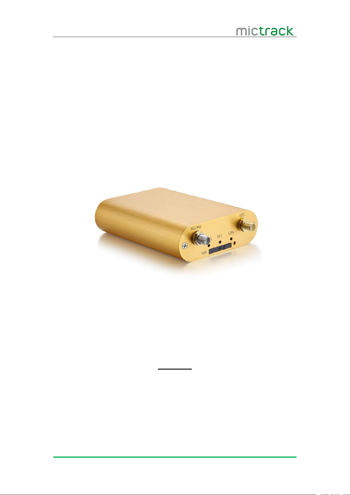
MT500 3G GPS Tracker
User Manual V3.0
Preface
Congratulations on choosing the Mictrack MT500 3G Vehicle GPS tracker. This
manual shows how to easily program and setup the tracker for best results. Make sure to
read this manual carefully before using this product, so as to avoid delays or confusion
with it’s operation. Please note that specifications and instructions are subject to change
without notice to facilitate product improvement. Updates and changes will be integrated
into the latest release. The manufacturer assumes no responsibility for any errors or
omissions in outdated documents.
Page 2

MT500 User Manual V3.0
http://www.mictrack.com
Contents
1. Overview
2. Application
3. Specifications..................................................................................................................................... 1
4. MT500 and Accessories.................................................................................................................. 2
5. Unit Diagram...................................................................................................................................... 3
6. Installation
6.1 SIM Card installation
6.2 LED Indications
6.2.1 CHG-Charge indicator (RED)................................................................................................... 4
6.2.2 SYS-System indicator (BLUE).................................................................................................. 4
6.2.3 GPS-GPS indicator (GREEN).................................................................................................. 5
6.3 Device Button Instruction
6.4 Install 3G & GPS Antenna
6.5 Connection of supplied wiring loom
6.6 Install the SOS switch.................................................................................................................. 6
6.7 Optimum locations for unit Installation......................................................................................6
6.7.1 Caution........................................................................................................................................... 7
7. Setup and Configuration
7.1 Setting Authorized Mobile Phone Numbers
7.2 Deleting authorized number
7.3 Changing the Admin password................................................................................................... 8
7.4 Instant Location Request (used to receive unit location via SMS).................................. 8
7.5 Instant Location Request (Phone Call Activated).................................................................. 8
7.6 SOS Alarm
7.7 Voice / Audio Monitoring (only for model E)
7.8 Round Geo-fence (Setting of size and shape of Geo-Fence)
7.8.1 Enable the Round Geo-fence.................................................................................................. 9
7.8.2 Disable the Round Geo-fence................................................................................................. 9
7.9 Square Geo-fence (Setting of dimensions and shape of Geo-Fence)............................. 9
7.9.1 Enable the Square Geo-fence
7.9.2 Disable the Square Geo-fence
7.10 Remote cut off fuel and ignition
7.11 External power cut off alarm.................................................................................................. 10
7.12 Towing alarm............................................................................................................................... 10
7.13 Low battery Alarm (internal backup battery).......................................................................10
7.14 Low battery Alarm (Vehicle Battery)
7.15 High Temperature Alarm
7.16 Over-Speed alarm (Alerts that the unit is exceeding a preset speed)
7.17 Set time zone............................................................................................................................. 10
7.18 Set GPRS device name........................................................................................................... 11
7.19 Set APN (Access Point Name).............................................................................................. 11
.............................................................................................................................................
...........................................................................................................................................
...........................................................................................................................................
.....................................................................................................................
...............................................................................................................................
..............................................................................................................
..........................................................................................................
..........................................................................................
.................................................................................................................
.............................................................................
.........................................................................................................
.......................................................................................................................................
..........................................................................
...........................................
.................................................................................................
................................................................................................
..............................................................................................
.....................................................................................
...........................................................................................................
.......................
10
10
10
1
1
3
3
4
5
5
6
7
7
8
8
8
9
9
9
9
Page 3

MT500 User Manual V3.0
http://www.mictrack.com
7.20 Set Tracking Server IP and PORT
7.21 Set GPRS Upload Interval Time
7.21.1 ACC ON (Upload default status is AUTO)
7.21.2 Vehicle Towed Alarm (vehicle moves whilst ACC is turned OFF)............................ 11
7.21.3 ACC OFF & Vehicle Stationary (Upload status is AUTOLOW)................................. 12
7.22 Invalid GPS Data Upload........................................................................................................ 12
7.23 SMS Response ON/OFF
7.24 Unit Phone Calling Control (useful for SIM Card data cost saving)
7.25 Set GPRS mileage and trip distance reporting
7.25.1 Set upload interval distance................................................................................................ 13
7.25.2 Clear the distance data........................................................................................................ 13
7.25.3 Check the current trip distance travelled......................................................................... 13
..........................................................................................................
.......................................................................................
............................................................................................
......................................................................
...........................
.................................................................
11
11
11
12
12
12
Page 4

MT500 User Manual V3.0
http://www.mictrack.com
1
1. Overview
The MT500 is the latest technology 3G GPS tracker, fully supporting WCDMA/UMTS
2. Application
3G WCDMA/UMTS network support
Real-time position acquiring
2 way voice communication (optional for Model “E” only)
Voice / Audio monitoring (optional for Model “E” only)
Vehicle trip history and mileage data on web tracking platform
SOS alarm button and real time reporting
ACC switch status alarm
Geo-Fence alarm and reporting
External power cut off alarm
Remote cut off fuel / ignition (optional)
Vehicle towing / Movement alarm
Over-Speed alarm and reporting
Backup battery low power alarm
Car battery low power alarm
High temperature alarm
Power saving / sleep mode
Door status sensor (optional)
Fuel level sensor (optional)
Siren(optional)
3. Specifications
Item
Specifications
Dimension
90(L)*70(W)*24(H)mm
Weight
138g
Input Voltage
12V-36V
Backup battery
700mAh/3.7v
mobile networks. This device can be used locate, track and monitor any remote target via
SMS, PC Computer or Mobile APP. It is commonly used to track and locate individual
vehicles, motorbikes or boats, and is a valuable tool for enhanced fleet management. The
user also can remotely cut off Fuel / Ignition and check the historical route travelled and
other vehicle data.
The MT500 has an excellent track record for stable performance and possesses a
wide variety of features.
Page 5
MT500 User Manual V3.0
http://www.mictrack.com
2
Item
Specifications
3G Frequency bands
MT500-E
900/2100MHz@UMTS
900/1800MHz@GSM
MT500-G
800/850/900/1900/2100MHz@UMTS
850/900/1800/1900MHz@GSM
Power consumption
60mA standby current
GPS Chip
U-BLOX7
GPS Sensitivity
-162dBm
Channel
56 Channel
Positioning Accuracy
10m
Hot start
1s on average
Warm start
15s on average
Cold start
30s on average
Working temperature
-20°C to 70°C
Humidity
5%~95% non-concretion
Antennas
External 3G & GPS antennas
Sensor
3D acceleration/movement sensor/ temperature sensor
LED
CHG/SYS/GPS
SIM Card interface
Standard Size SIM
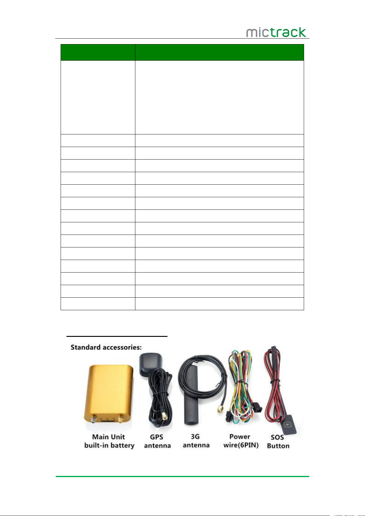
4. MT500 and Accessories
Page 6
MT500 User Manual V3.0
http://www.mictrack.com
3
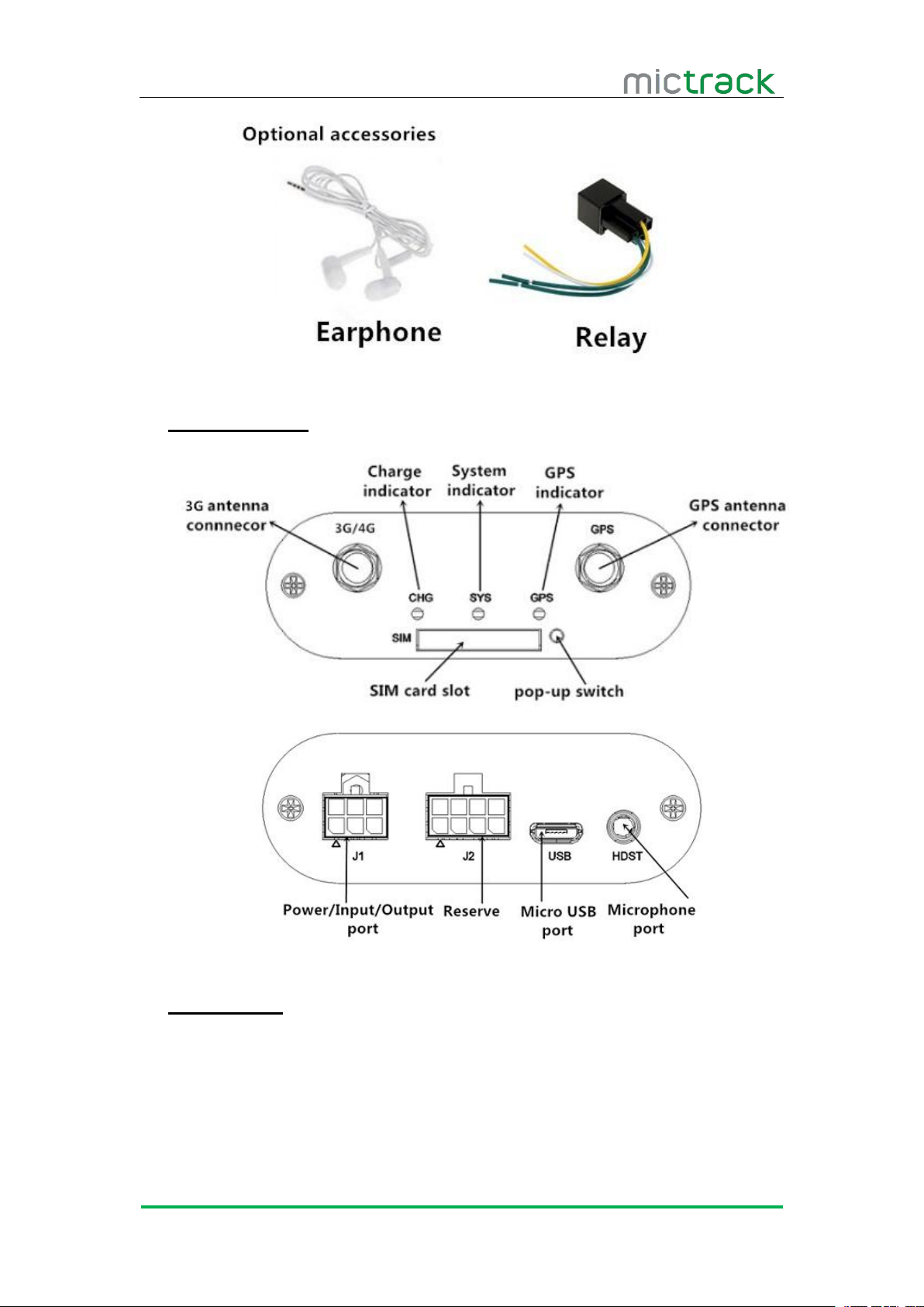
5. Unit Diagram
6. Installation
6.1 SIM Card installation
Please read the following before installing the SIM card:
Ensure the SIM card has minimum balance
Ensure the SIM card has caller ID and HSPA functions enabled
Ensure the SIM card PIN is disabled, and call forwarding not active
Page 7
MT500 User Manual V3.0
http://www.mictrack.com
4
Send a test SMS to and from the SIM card using a mobile phone
Power off the device before installing the SIM card
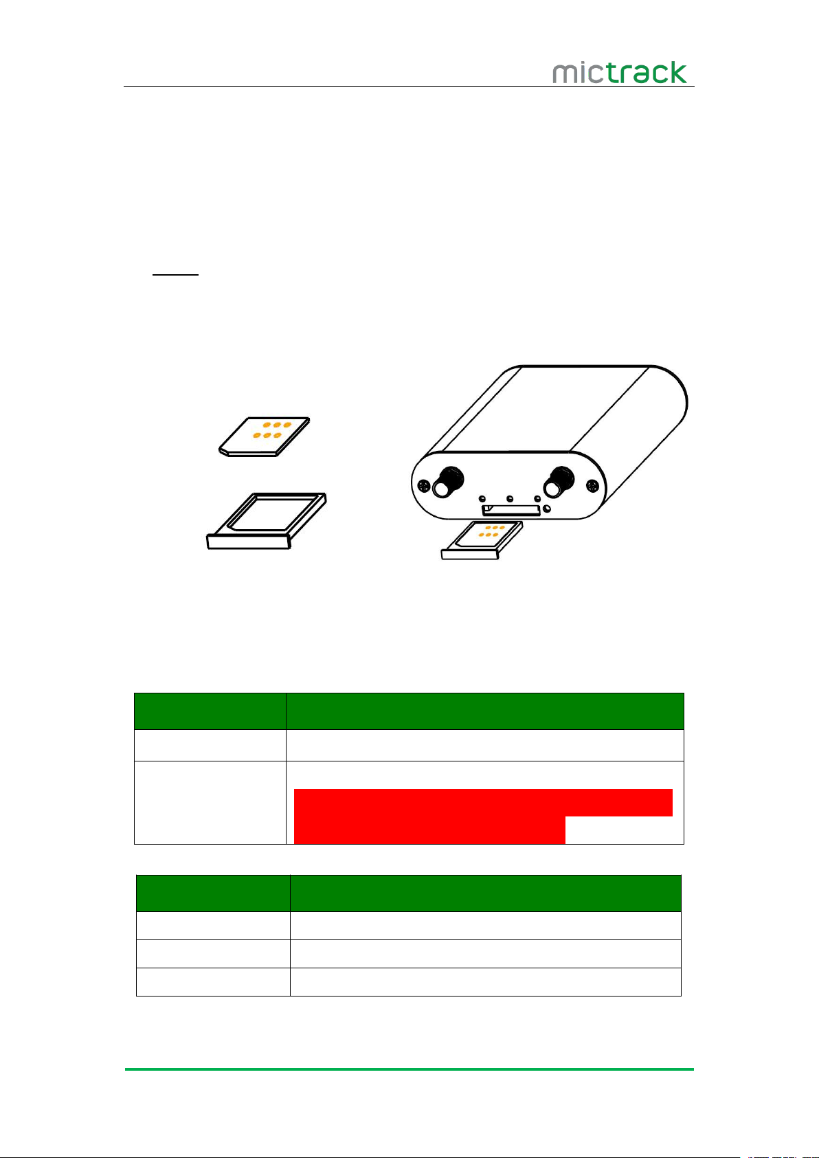
To install the SIM card, perform the following operations:
1. Insert the SIM card into the SIM card plastic tray.
2. Ensure the SIM card has metal contacts facing up (Diagram #1).
3. Gently slide the SIM Tray into the SIM Slot (Diagram #2).
The device only supports Standard Size SIM card;
To remove SIM card, use paperclip to press the SIM card pop-out button to eject the
6.2 LED Indications
6.2.1 CHG-Charge indicator (RED)
6.2.2 SYS-System indicator (BLUE)
Status
Description
Constant ON
No SIM Card (or) No Network Reception
OFF
Vehicle Parked – ACC Power OFF
Quick flash
Normal Working Mode
Status
Description
Constant ON
Currently Charging
OFF
Charging Complete
(Note: it will auto-charging when backup battery voltage
is low and LED light, or LED no light.)
Note:
SIM card tray.
Diagram #1 Diagram #2
Page 8
MT500 User Manual V3.0
http://www.mictrack.com
5
6.2.3 GPS-GPS indicator (GREEN)
6.3 Device Button Instruction
Button
Description
Power
ON/OFF
Insert the SIM tray to POWER ON the unit; Take out SIM
tray to POWER OFF the unit
Connect the external power to POWER ON; Disconnect the
power to POWER OFF
SOS Button
Press and hold the button for 3x seconds, the unit will call the
authorized phone numbers in sequence, then send position data
to authorized phone numbers and Web Tracking Platform.
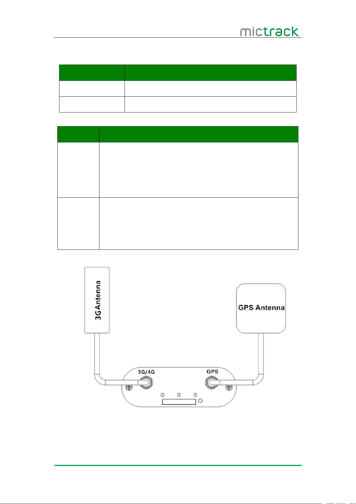
6.4 Install 3G & GPS Antenna
Connect the 3G Antenna firmly to "3G/4G" Socket (Note: the 3G antenna is
non-directional and can be hidden anywhere inside the vehicle)
Connect the GPS Antenna firmly to “GPS” socket (Note: it is recommended that
Status
Description
OFF
GPS / Satellites Unavailable – Out of Range
Quick flash
GPS/Satellite Locked – Normal Mode
the antenna is facing up to the sky, so that the side with printed text is facing
outwards / upwards) preferably NOT under or behind metal. Secure the antenna
Page 9
MT500 User Manual V3.0
http://www.mictrack.com
6
using the double sided tape provided
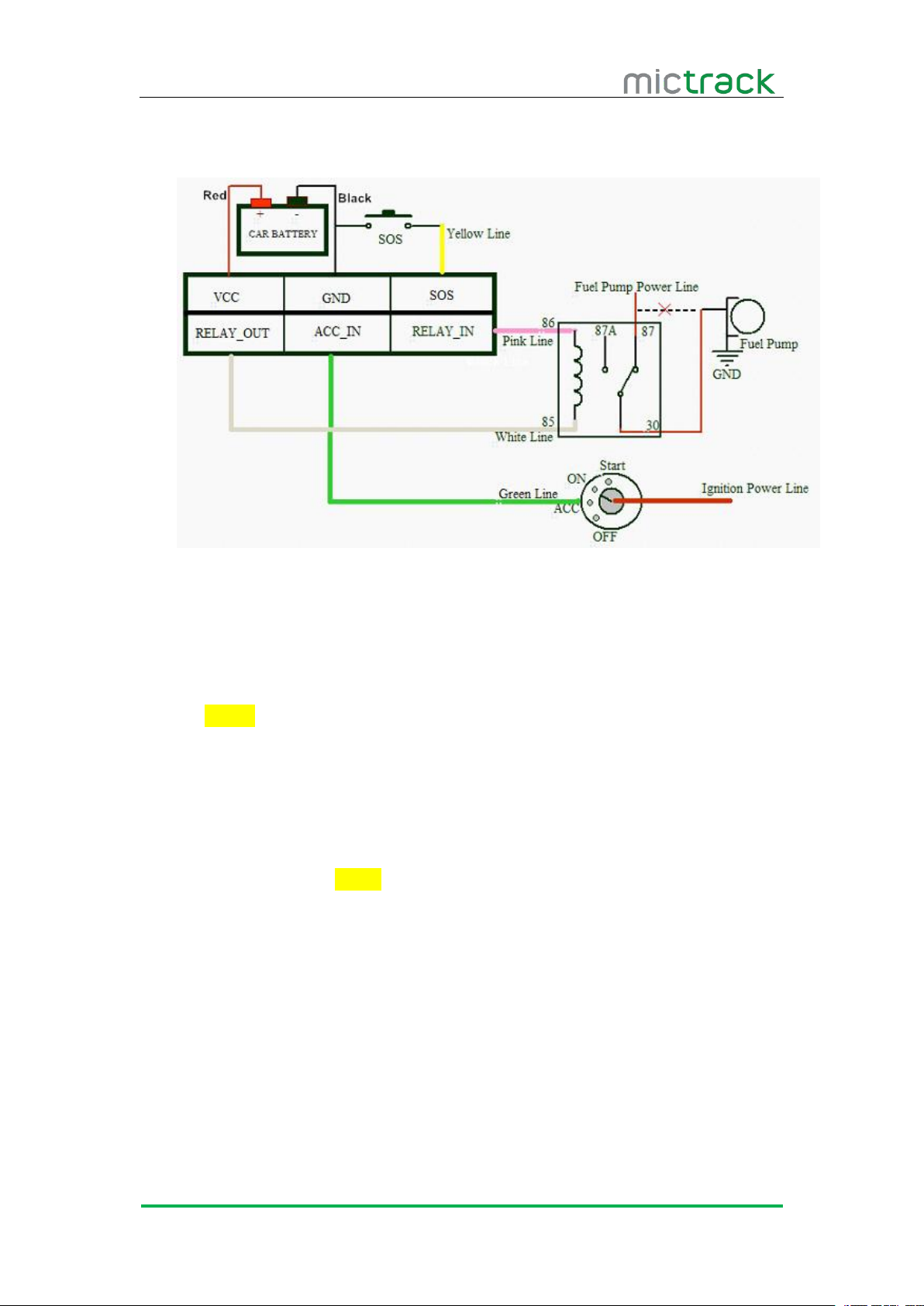
6.5 Connection of supplied wiring loom
Red: Connect to Car battery(+)
Red: Connect to constant 12V Car Battery(+)
Black: Connect to Earth (Chassis) Car battery(-)
Green: Connect to ACC switched 12V Power
Yellow: Connect to red wire of supplied SOS switch
White: Connect to Relay terminal (85)
Pink: Connect to Relay terminal (86)
6.6 Install the SOS switch
Red: connect to Yellow wire from supplied wiring loom
Black: connect to Earth (Chassis) Car battery(-)
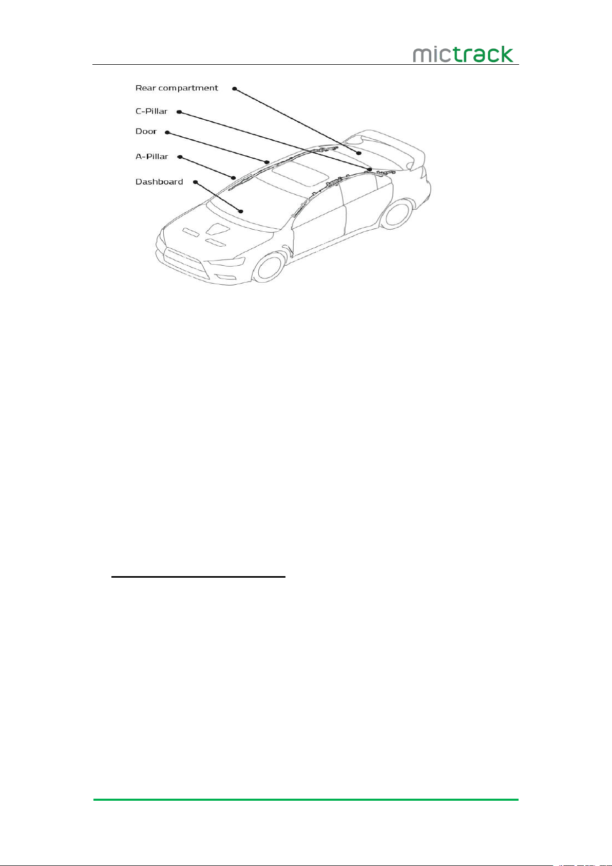
6.7 Optimum locations for unit Installation
When installing the device, please connect supplied wiring loom as follows: (or
contact our sales team for help)
Note: Relay is optional for remote fuel / ignition shut-off.
Below are the recommended areas available within a vehicle for unit installation.
These are suggestions only, as depending on the vehicle type, there may be many
possible locations to hide/install the unit.
Page 10
MT500 User Manual V3.0
http://www.mictrack.com
7
6.7.1 Caution
Avoid placing GPS Antenna (or units with internal GPS antenna) under any metal
surfaces, as this may affect satellite lock and functionality.
Do not install unit right next to stereo, CB radio, heater, speakers or alarm
Unit must be firmly mounted or cable tied to a surface, not hanging by wiring
Do not place the unit next to steering column or any moving parts.
It is recommended to place the GPS Antenna (or units with internal GPS antenna)
Device can be placed in other areas or storage compartments of the vehicle
7. Setup and Configuration
7.1 Setting Authorized Mobile Phone Numbers
systems.
loom etc.
in locations that are exposed to the sky (i.e. under plastic dashboard, under rear
parcel shelf, at base of rear windscreen, inside C-Pillar areas or doors, etc)
(internally or externally) depending on the vehicle, truck, boat or motorcycle, as
long as there is access to power and a clear signal from satellites.
Note: When sending SMS command to the unit, do NOT use spaces or symbols not
listed below. [brackets and + are for instructional use only] * and # are valid command
parameters.
Following a successful command, you should always receive a reply SMS from the
unit. Be patient, as this may take some time depending if the unit is required to reboot to
process the command. Failure to reply will indicate either an incorrect SMS Command, or
the unit has powered off, lost GSM Mobile signal or run out of SIM Card credit.
SMS Command format: mobile number+password+[command parameter]
Note: Command Parameter here is the sequence of the mobile number
Page 11

MT500 User Manual V3.0
http://www.mictrack.com
8
i.e. [1=Admin] or [2=SOS call number]
The defaulted password is 0000.
It can authorize up to 3 phone numbers.
7.2 Deleting authorized number
7.3 Changing the Admin password
7.4 Instant Location Request (used to receive unit location via SMS)
7.5 Instant Location Request (Phone Call Activated)
7.6 SOS Alarm
7.7 Voice / Audio Monitoring (only for model E)
For example: *13424392330*0000*1**
Unit Reply: SET USER NUMBER 1 OK.
Note:
SMS Command format: password+number+[command parameter]
Note: Command Parameter here is the sequence of the mobile number
i.e. [1=Admin] or [2=SOS call number]
For example: **0000*1**
Unit Reply: DELETE USER NUMBER 1 OK.
SMS Command format: 777+new password+old password
For example: 77712340000
Unit Reply: SET USER PASSWORD OK.
SMS Command format: 666+password
For example: 6660000
When sent, this command will result in a Unit Reply SMS as follows:
ID:865662000409210 [Units IMEI #]
Date:05:36:59 11/11/2016
Fix:A State:SMS
http://maps.google.com/maps?q=+22.63146%2c1+114.03701
Note: This link can to be opened on any Smart Phone to reveal the Google Maps
Location of the unit at the time of request.
If the unit receives an incoming call from one of it’s 3x authorized numbers, and the
call is hung up after ringing only 2-5 times, the device will send an SMS containing it’s
location to it’s authorized phone number, and then upload it’s location data to the Web
Tracking Platform server along with the status description “CALL”
When the SOS / Duress switch is pressed for 3 seconds, the unit will automatically
call the authorized phone numbers, and then send it’s location to authorized phone
number via SMS, and also upload location data to the Web Tracking Platform server along
with the status description “SOS”
To disable the voice/audio monitoring
SMS Command format: 000+password
Page 12

MT500 User Manual V3.0
http://www.mictrack.com
9
For example: 0000000
7.8 Round Geo-fence (Setting of size and shape of Geo-Fence)
7.8.1 Enable the Round Geo-fence
7.8.2 Disable the Round Geo-fence
7.9 Square Geo-fence (Setting of dimensions and shape of Geo-Fence)
7.9.1 Enable the Square Geo-fence
7.9.2 Disable the Square Geo-fence
7.10 Remote cut off fuel and ignition
Unit Reply: SET VOICE MONITOR:OFF.
To enable the voice/audio monitoring monitor
SMS Command format: 001+password
For example: 0010000
Unit Reply: SET VOICE MONITOR:ON.
Note: Default setting is MONITOR OFF
SMS Command format: 005+password+R+[Command Parameter]
Note: Command Parameter here is fence diameter in KM [0.1~999.9]
For example: 0050000R1.0
Unit Reply: SET ROUND GEO-FENCE:ON
SMS Command format: 211+password
For example: 2110000
Unit Reply: SET ROUND GEO-FENCE: ON.
SMS Command format: 210+password
For example: 2100000
Unit Reply: SET ROUND GEO-FENCE: OFF.
SMS Command format: 006+password+G1,IO/I/O,E/W longitude upper limit+N/S
latitude upper limit,E/W longitude lower limit+N/S latitude lower limit.
For example: 0060000G1,IO,E114.04540N22.59034,E114.05978N22.59797
Unit Reply: SET SQUARE GEO-FENCE1(IO)OK.
SMS Command format: 311+password
For example: 3110000
Unit Reply: SET SQUARE GEO-FENCE: ON.
SMS Command format: 310+password
For example: 3100000
Unit Reply: SET SQUARE GEO-FENCE: OFF.
To remotely Cut-Off fuel or power
SMS Command format: 940+password
For example: 9400000
Unit Reply: SET OILWAY DISCONNECT.
To remotely Resume fuel or power
Page 13

MT500 User Manual V3.0
http://www.mictrack.com
10
SMS Command format: 941+password
7.11 External power cut off alarm
7.12 Towing alarm
7.13 Low battery Alarm (internal backup battery)
7.14 Low battery Alarm (Vehicle Battery)
7.15 High Temperature Alarm
7.16 Over-Speed alarm (Alerts that the unit is exceeding a preset speed)
7.17 Set time zone
For example: 9410000
Unit Reply: SET OILWAY RECOVERY CONNECT.
Note: The default setting for the Cut-Off feature is OFF
If the external power to the unit is disconnected, [i.e. unit tampering or vehicle battery
removal] the unit will call the authorized phone numbers, and then send location data to
the authorized phone number and upload location data to the Web Tracking Platform
server along with the status description “DEF”
If the vehicle was be moved or towed when ACC is turned OFF, it will SMS location
data to the authorized phone number, and upload location data to the Web Tracking
Platform server along with the status description “TOWED”
When the unit’s internal backup battery is low, it will SMS the authorized phone
number, and upload location data to the Web Tracking Platform server along with the
status description “BLP”
When the vehicle battery is low, it will SMS the authorized phone number, and upload
location data to the Web Tracking Platform server along with the status description “CLP”
When the devices internal temperature is high [preset value] it will SMS the
authorized phone number, and upload location data to the Web Tracking Platform server
along with the status description “HT”
SMS Command format: #122#user password#[Command Parameter]##
Note: Command Parameter here is [Km/Hour]
Example: #122#0000#100##
Unit Reply: SET SPEED LIMIT:ON
To disable the Over-Speed Alarm
SMS Command format: #122#0000#0##
Note: Command Parameter here is [0=OFF]
Unit Reply: SET SPEED LIMIT:OFF.
Note: Speed is in KM/H, Maximum setting = [999].
SMS Command format: 896+password+ [+/-]HH:MM
Note: Command Parameter here is [Plus or Minus GMT]&[Hours/Minutes]
For example: 8960000+10:00
Reply: SET TIME ZONE:+08:00
Page 14

MT500 User Manual V3.0
http://www.mictrack.com
11
Note: The default is Greenwich Time (UTC). [i.e. Melbourne Australia = +10:00]
7.18 Set GPRS device name
7.19 Set APN (Access Point Name)
7.20 Set Tracking Server IP and PORT
7.21 Set GPRS Upload Interval Time
7.21.1 ACC ON (Upload default status is AUTO)
7.21.2 Vehicle Towed Alarm (vehicle moves whilst ACC is turned OFF)
SMS Command format: #801#password#device name##
For example: #801#0000#MT500##
Unit Reply: SET SERVER USER NAME OK.
Note: Maximum 10 Characters
SMS Command format 1: #803# password#APN##
For example : #803#0000#telstra.internet##
SMS Command format 2: #803#password#APN#APN user name# APN password##
For example: #803#0000#CMNET#INTERNET#INTERNET##
Reply: SET GPRS APN OK.
Note: please contact your SIM Card provider to get the correct APN details
(Most SIM Card GSM providers do not use passwords or usernames for access
– it is already encoded into the SIM Card)
SMS Command format: #804#password#IP address(or domain) #port##
Example:#804#0000#112.95.164.248#7780##(or) #804#0000#e.trackits.com#7700##
Reply: SET SERVER IP AND PORT OK.
This sets how often [in seconds] the unit sends location data back to the Tracking
Platform whilst the ACC is switched on. This will affect accuracy and data usage.
SMS Command format: #805#password#interval time#[command parameter]##
Note: Command Parameter here [1=ON] & [0=OFF]
For example:#805#0000#10#1##
Unit Reply: SET GPS PERIODIC UPLOAD ON.
Note: interval time maximum [10,65535]seconds
Unit Reply: SET GPS PERIODIC UPLOAD OFF.
SMS Command format: #809#password#interval time#[command parameter]##
Note: Command Parameter here [1=ON] & [0=OFF]
For example:#809#0000#10#1##
Unit Reply: SET GPS TOWED UPLOAD ON.
Note: interval time maximum [10,65535]seconds
Unit Reply: SET GPS TOWED UPLOAD OFF.
Page 15

MT500 User Manual V3.0
http://www.mictrack.com
12
7.21.3 ACC OFF & Vehicle Stationary (Upload status is AUTOLOW)
[Periodic upload of vehicle status to the Web Tracking Platform server whilst ACC off
7.22 Invalid GPS Data Upload
7.23 SMS Response ON/OFF
7.24 Unit Phone Calling Control (useful for SIM Card data cost saving)
7.25 Set GPRS mileage and trip distance reporting
– variable to save SIM data costs when parked for long periods and Power Saving]
SMS Command format: #807#password#interval time##
For example: #807#0000#2##
Unit Reply: SET GPS POWER SAVING UPLOAD ON.
Note: interval time maximum [2,1440] minutes [If interval time = 0, it will stop upload]
Unit Reply: SET GPS POWER SAVING UPLOAD OFF.
To turn Invalid data upload ON
SMS Command format: 081+ password
For example: 0810000
Unit Reply: INVALID DATA UPLOAD:ON
To turn Invalid data upload OFF
SMS Command format: 080+ password
For example: 0800000
Unit Reply: INVALID DATA UPLOAD:OFF
To turn SMS messages OFF
SMS Command format: 160+password
For example: 1600000
Unit Reply: SET SEND SMS:OFF.
To turn SMS messages back ON
SMS Command format: 161+password
For example: 1610000
Unit Reply: SET SEND SMS:ON.
Note: if you want to disable the SMS alerts, send 1600000
To turn OFF unit Calling Alerts
(i.e. to save SIM data costs)
SMS Command format: 150+password
For example: 1500000
Unit Reply: SET VOICE CALL:OFF
To turn ON unit Calling Alerts
SMS Command format: 151+password
For example: 1510000
Unit Reply: SET VOICE CALL: ON
This sets how often [in kilometres] the unit uploads data of “trip distance travelled”
back to the Tracking Platform whilst the ACC is switched on. This will affect accuracy
Page 16

MT500 User Manual V3.0
http://www.mictrack.com
13
and data usage. This setting is often used for International Shipping clients and
7.25.1 Set upload interval distance
7.25.2 Clear the distance data
7.25.3 Check the current trip distance travelled
Tips:
How to setup APN: https://www.mictrack.com/apn-settings-for-mictrack-gps-trackers
How to use Mictrack Server: https://www.mictrack.com/how-to-use-mictrack-server
Global Frequency bands check: https://www.mictrack.com/4g-lte-frequency-bands-list
Trucking Fleets to save data on long journeys.
SMS Command format: #141#password#[command parameter]##
Note: Command Parameter here is [0=OFF] &[1000=1000 Kms]
Unit Reply: SET GPS MILEAGE STATISTICS:ON/OFF
SMS Command format: #142#password#[command parameter]##
Note: Command Parameter here is [0=clear current trip distance]
& [1=clear total distance travelled]
Unit Reply: SET GPS MILEAGE STATISTICS:CLEAR CURRENT/ALL
SMS Command format: #143#password##
For example: #143#0000##
Unit Reply: TOTAL GPS MILEAGE:X.X Km
CURRENT GPS MILEAGE:X.X Km
Note: Please remember to monitor the credit balance of your SIM card, to
avoid confusion or delays in setting up your new unit. This can be a common issue,
especially when initially setting up a new unit, and the unit fails to reply to a correct
SMS command sequence.
If you have any questions please do not hesitate to contact us [email protected].
 Loading...