

Micsig TO1102, TO1074, TO1072, TO1104, TO1152 User Manual

Tablet Oscilloscope tBook mini TO1000 Series
Shenzh en M icsig I ns trument s Co ., Ltd.
User Manual

TABLE OF CONTENTS
Cha rt
1
Important safety information
1.1 General safety summary
1.2 Service safety summary
1.3 Terms in the manual
1.4 Symbols on the product
Preface
2.1 General introduction
2.2 Key features
Installing your scope
3.1 Check shipped accessories
3.2 Operating requirements
3.3 Input signal requirements
3.4 Secure (lock) the oscilloscope
Operating your instrument
5.1 Gestures
5.2 Osc il lo sc op e ba si c op er ation
5.3 Optional function up gr ad e
Remote control your instrument
6.1 Com pu te r so ft wa re I ns tr uction
6.2 APP (and ro id /i OS )
Data sheet
Getting acquainted with your instrument
4.1 Fro nt p an el a nd r ea r pa ne l
4.2 Using the stand
4.3 Installing the carry strap
4.4 Powering the oscilloscope
4.5 Probe compensation
4.6 The user interface screen
4.7 Instrument setting (system information,
language, upgrade, WLAN)
Cha rt
2
Cha rt
3
Cha rt
4
Cha rt
5
Cha rt
6
Cha rt
7

1 Important safety information
Chap ter
Safety information provides warnings and cautions that help you operate the instrument safely and keep the instrument in a safe wor king
condition.
1.1 General safety summary
This manual contains information and warnings that m ust be fo llowed by th e user fo r safe op eration an d to keep th e p rodu c t i n a sa f e
condition.
To safely perform service on this product, see the Service safety summary that follows the General safety summary.
Use the product only as specified. Review the following safety precautions to avoid injury and prevent damage to this product or any
products connected to it. Carefully read all instructions. Retain these instructions for future reference.
Comply with local and national safety codes.
For correct and safe operation of the product, it is essential that you follow generally accepted safety procedures in addition to the
safety precautions specified in this manual.
The product is designed to be used by trained personnel only.
Only qualified personnel who are aware of the hazards involved should remove the cover for repair, maintenance, or adjustment.
Before use, always check the product with a known source to be sure it is operating correctly. This product is not intended for detection
of hazardous voltages.
Use personal protective equipment to prevent shock and arc blast injury where hazardous live conductors are exposed.
While using this product, you may need to access other parts of a larger system. Read the safety sections of the othe r componen t
manu als for w arnings an d cauti ons rel ated to oper ating t he syst em.
When incorporating this equipment into a system, the safety of that system is the responsibility of the assembler of the system.
1.1.1 To avoid fire or personal injury
Use proper power cord. Use only the power cord specified for this product and certified for the country of use. Do not use the provided
power cord for other products.
01

Connect and disconnect properly. Do not connect or disconnect probes or test leads while they are connected to a voltage source.
Use only insulated voltage probes, test leads, and adapters supplied with the product, or indicated by Micsig to be suitable for the
product.
Observe all terminal ratings. To avoid fire or shock hazard, observe all rating and markings on the product. Consult the product
manual for further ratings information before making connections to the product. Do not exceed the Measurement Category (CAT)
rating and voltage or current rating of the lowest rated individual component of a product, probe, or accessory. Use caution when
using 1:1 test leads because the probe tip voltage is directly transmitted to the product.
Do not a pply a po tential to a ny term inal, i ncluding t he comm on term inal, th a t e xcee ds the maxi mum rat ing of that te r mina l.
Do not float the common terminal above the rated voltage for that terminal.
Do not operate without covers. Do not operate this product with covers or panels removed, or with the case open. Hazardous voltage
exposure is possible.
Avoid exposed circuitry. Do not touch exposed connections and components when power is present.
Do not operate with suspected failures. If you suspect that there is damage to this product, have it inspected by qualified service
personnel.
Disable the product if it is damaged. Do not use the product if it is damaged or operates incorrectly. If in doubt about safety of the
prod uct, tu rn it off and disc onnec t the pow er cord. Cle arly ma rk the pr oduct to pre vent it s furth er operati on.
Before use, inspect voltage probes, test leads, and accessories for mechanical damage and replace when damaged. Do not use probes
or test leads if they are damaged, if there is exposed metal, or if a wear indicator shows.
Ground the produc t. This product is grounded through the grounding conductor of the power cord. To avoid electric shock, the
grounding conductor must be connected to earth ground. Before making connections to the input or output terminals of the product,
ensure that the product is properly grounded. Do not disable the power cord grounding connection.
Power disconnect. The power cord disconnects the product from the power source. See instructions for the location. Do not position
the equipment so that it is difficult to operate the power cord; it must remain accessible to the user at all tim es to all ow for quick
disconnection if needed.
02

Keep product surfaces clean and dry. Remove the input signals before you clean the product.
Provide pro per ventilation. Refer to the manual's installation instructions for details on installi ng the pr oduct so it has prope r
ventilation.
Slots and openings are provided for ventilation and should never be covered or otherwise obstructed. Do not push objects into any of
the openings.
Provide a safe working environment. Always place the product in a location convenient for viewing the display and indicators.
Be sure your work area meets applicable ergonomic standards. Consult with an ergonomics professional to avoid stress injuries.
Use care when lifting and carrying the product. This product is provided with a handle for lifting and carrying.
Use only the Micsig rackmount hardware specified for this product.
Use proper fuse. Use only the fuse type and rating specified for this product.
Wear eye protection. Wear eye protection if exposure to high-intensity rays or laser radiation exists.
Do not operate in wet/damp conditions. Be aware that condensation may occur if a unit is moved from a cold to a warm environment.
Do not operate in an explosive atmosphere.
1.1. 2 Probes an d test leads
Before connecting probes or test leads, connect the power cord from the power connector to a properly grounded power outlet.
Keep fingers behind the finger guards on the probes.
Remove all probes, test leads and accessories that are not in use.
Examine the exterior of the product before you use it. Look for cracks or missing pieces.
Use only specified replacement parts.
03

The maximum floating voltage from the probe reference lead to earth ground.
These two voltage ratings depend on the probe and your application. Refer to the Specifications section of the manual for more
information.
WARNING. To prevent electrical shock, do not exceed the maximum measurement or maximum floating voltage for the
oscilloscope input BNC connector, probe tip, or probe reference lead.
!
Connect and disconnect properly. Connect the probe output to the measurement product before connecting the probe to the circuit
under test. Connect the probe reference lead to the circuit under test before connecting the probe input. Disconnect the probe input
and the probe reference lead from the circuit under test before disconnecting the probe from the measurement product.
Connect and disconnect properly. De-energize the circuit under test before connecting or disconnecting the current probe.
Connect the probe reference lead to earth ground only.
Do not connect a current probe to any wire that carries voltages above the current probe voltage rating.
Inspect the probe and accessories. Before each use, inspect probe and accessories for damage (cuts, tears, or defects in the probe
body, accessories, or cable jacket). Do not use if damaged.
Do not connect a current probe to any wire that carries voltages above the current probe voltage rating.
1.2 Service safety summary
The Service safety summary section contains additional information required to safely perform service on the product. Only qualified
personnel should perform service procedures. Read this Service safety summary and the General safety summary before performing
any service procedures.
The maximum measurement voltage from the probe tip to the probe reference lead.
Beware of high voltages. Understand the voltage ratings for the probe you are using and do not exceed those ratings. Two ratings
are important to know and understand:
Use only correct Measurement Category (CAT), voltage, temperature, altitude, and amperage rated probes, test leads, and adapters
for any measurement.
04

Terms on the product
These terms may appear on the product:
DANG ER indi cates an inj ury haz ard imm ediately a ccess ible as y ou read the ma rking .
WARNING in dicates an i njury h azard not immedia tely ac cessible as you rea d the mar king.
CAUT ION ind icates a haz ard to pr opert y includin g the pro duct.
When this symbol is marked on the product, be sure to consult the manual to find out the nature of the potential hazards and any actions
which have to be taken to avoid them. (This symbol may also be used to refer the user to ratings in the manual.)
1.4 Symbols on the product
These terms may appear in this manual:
WARNING. Warning statements identify conditions or practices that could result in injury or loss of life.
CAU TION. Caution statements identify conditions or practices that could result in damage to this product or other property.
!
Use care when servicing with power on. Dangerous voltages or currents may exist in this product. Disconnect power, remove battery
(if applicable), and disconnect test leads before removing protective panels, soldering, or replacing components.
Verify safety after repair. Always recheck ground continuity and mains dielectric strength after performing a repair.
1.3 Terms in the manual
Disconnect power. To avoid electric shock, switch off the product power and disconnect the power cord from the mains power before
removing any covers or panels, or opening the case for servicing.
Do not service alone. Do not perform internal service or adjustments of this product unless another person capable of rendering first
aid and resuscitation is present.
To avoid electric shock. Do not touch exposed connections.
05

Ground Terminal
The following symbols may appear on the product:
High Voltage
Caution Refer to Manual
Protective Ground(earth) Terminal
Chassis Ground
!
06

2 Prefac e
Chap ter
2.1 General introduction
tBook mini TO1000 series uses 8 inches industry TFT-LCD & 800*600 pixels display resolution, 2 or 4 channels, 70MHz & 100MHz
& 150MHz bandwidth, 1 G Sa/s sample rate & up to 28Mpts memory depth and supports multi-touch capacitive screen, 256 intensity
grading display and also supports LAN, WiFi, HDMI, USB Host, USB Device, Trigger out port and like that. Therefore, this series is
your best choice for testing work.
tBook mini TO1000 series integrates all of advantages in one instrument: super low budget, rapid response, easy operation, technology
UI and abundant features.
2.2 Key features
70MHz, 100MHz, 150MHz bandwidth, 2 or 4 analog channels
1GSa/s real-time sample rate
14Mpts or 28Mpts memory depth
Up to 80,000wfm/s waveform capture rate
Up to 5 hours lithium battery (options)
8"TFT LCD & 800*600 pixels high resolution Multi-touch capacitive screen
Gradient waveform display with 256 intensity levels
Trigger functions: Edge, Pulse Width, Logic, Video trigge r, Time Out, Slope, Runt, Nth edge
Built-in 8G memory, waveforms and screenshots can be viewed and edited in scope
Various I/O port, LAN, Wi-Fi, USB2.0, USB Device, HDMI, Trigger out
07

3 Installing your scope
Chap ter
3.1 Check shipped accessories
3.1.1 Inspect the shipping container for damage.
If your shipping container appears to be damaged, keep the shipping container or cushioning material until you have inspected the
contents of the shipment for completeness and have checked the oscilloscope mechanically and electrically.
3.1.2 Verify that you received the following items and any optional accessories you may have ordered:
Micsig tablet oscilloscope tBook mini TO1000 Series
Power adaptor
Power cord(country of origin determines specific type)
Oscilloscope probes(Two probes for 2-channel models, four probes for 4-channel models)
Quick-Start(Read it from the homepage of the Micsig TO1000 Series oscilloscope)
BNC Cap
3.2 Operating requirements
Use the oscilloscope within the required operating temperature, power, altitude, and signal input voltage ranges to provide the mostaccurate measurements and safe instrument operation.
3.2.1 Environment requirements
Carry Strap
Handbag
Screen protector film
Battery
Accessories you may ordered:
08

Humidity (Operating Non-operating) /
5%~85% / 5%~90%,25℃
Altitude (Operating / Non-operating)
3000 m / 12000 m
3.2.2 Environment requirements
Characteristic
Description
Adapter Supply Voltage, Frequency
100VAC to 240VAC , 50Hz / 60Hz
Power Adapters
12VDC *5A
7.4V 8000mAh
Battery
Standard Lithium Battery capacity
4 to 8 hours
Continuous Working Hours,Typical
3.3 Input signal requirements
Keep the input signals within allowed limits to ensure the most accurate measurements and prevent damage to the analog and digital
probes or instrument.
Make sure that input signals are within the following requirements.
Characteristic Description
Temperature (Operating /Non-operating)
0℃ 45℃ 40℃ 60℃~+ /- ~+
Input Impedance
Probe Attenuation Coefficient
Input
(1 MΩ±1%) || (14.5 pF±3 pF)
1mx-10kx, 1-2-5 step
Description
Input Coupling
DC, AC, ground
Differential delay, Typical
Between any two channels which has same scales and couplings <40ps
09
3.4 Secure (lock) the oscilloscope.
Lock an oscilloscope to a test bench or equipment rack to prevent property loss.
Attach a standard laptop security lock to the left side panel of the oscilloscope, to
secure the oscilloscope to a workbench, rack, or other location.
10
4 Gett ing acq uainted wi th your ins trume nt
Chap ter
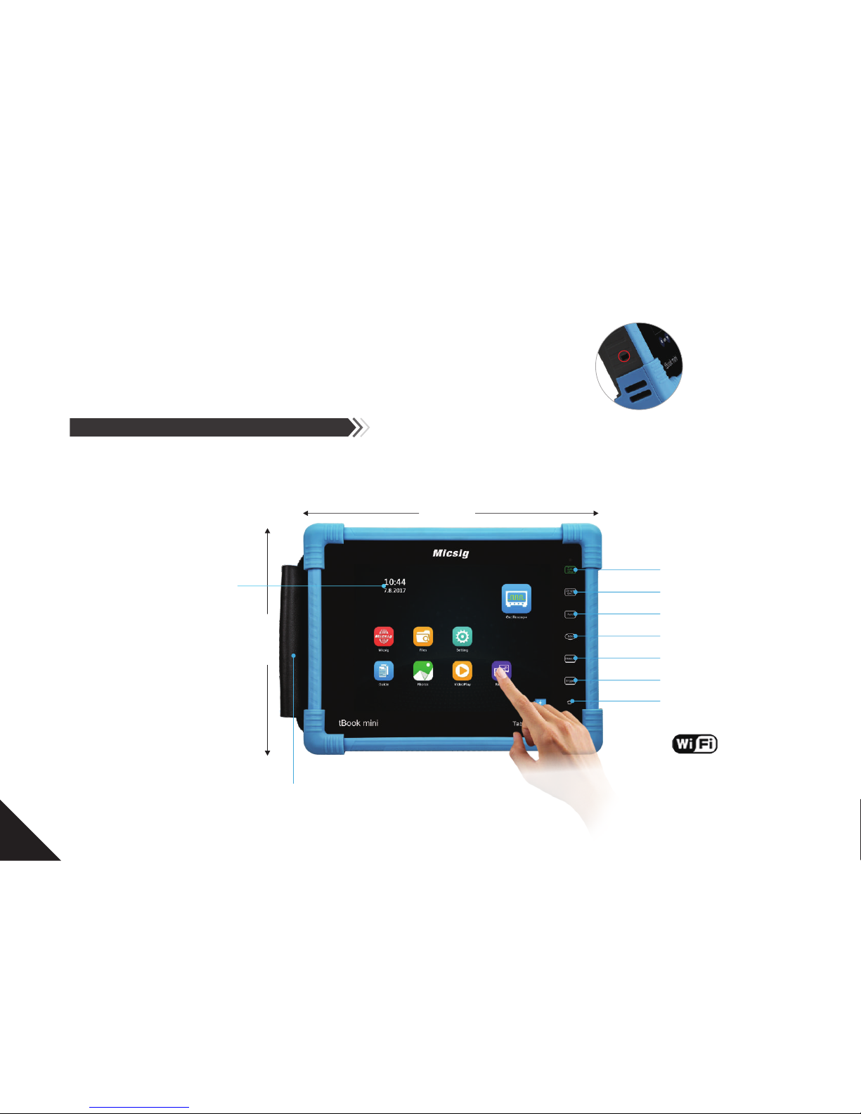
4.1 Front panel and Rear panel
250mm
8 inches TFT LCD
800*600 pixels
200mm
Run/stop
Single SEQ
Auto
50%
Measure
Tri gger
Home
Carry Strap(optional)
11
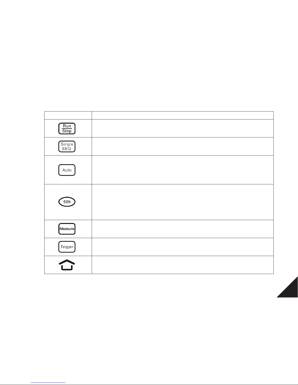
Touch button Description
Run/Stop:Touch to start / Stop acquisition
Single SEQ: Touchto trigger on a single waveform
Auto: Touchto activate automatic waveform setup
Note: Automatic setup requires the frequency of thetest signal to beat least 20Hz if thesignal is
sinusoidal. Otherwise, automatic setup may fail and the quick parametermeasurement function
displayed in the menu will also beunavailable.
50%: Touch to set:
The vertical position of the current channel waveform to the zero point
The horizontal position of the current channel waveform to center of the screen
The trigger level to the center of the trigger channel's waveform
The activecursor back to the center of the scree
Measure:Touch to turn on / off measurement menu
Trigger: Touch to turn on / off trigger menu
Home: Touch to return to the home page

12
Aux ou t
Info rmati ons: Brand , Model , S / N, Manu facturer
Chan nels
4.2 Using the stand
Pull the tilt stand upward, then you can open
Tilt stand

13
4.3 Installing the carry strap
4.4 Powering the oscilloscope
When you first time to use the oscilloscope, please connect the power cord to the oscilloscope, then press the right side power
button make oscilloscope forced shutdown.
Power requirements:
Line voltage, Line 100-120 Vac, 50/60/400 Hz
Frequency, and power 100-240 Vac, 50/60 Hz100 W max
Note s:
If there is one battery in your oscilloscope, the battery will be activated when you turn on in the first time.
4.4.1 Power ON
4.4.2 Power Off
Press power button , enter the shutdown interface, tap to turn off the oscilloscope.
Press and hold the power button make oscilloscope forced shutdown.
Warning: Forced shutdown may cause losing data.
!
shutdown
14
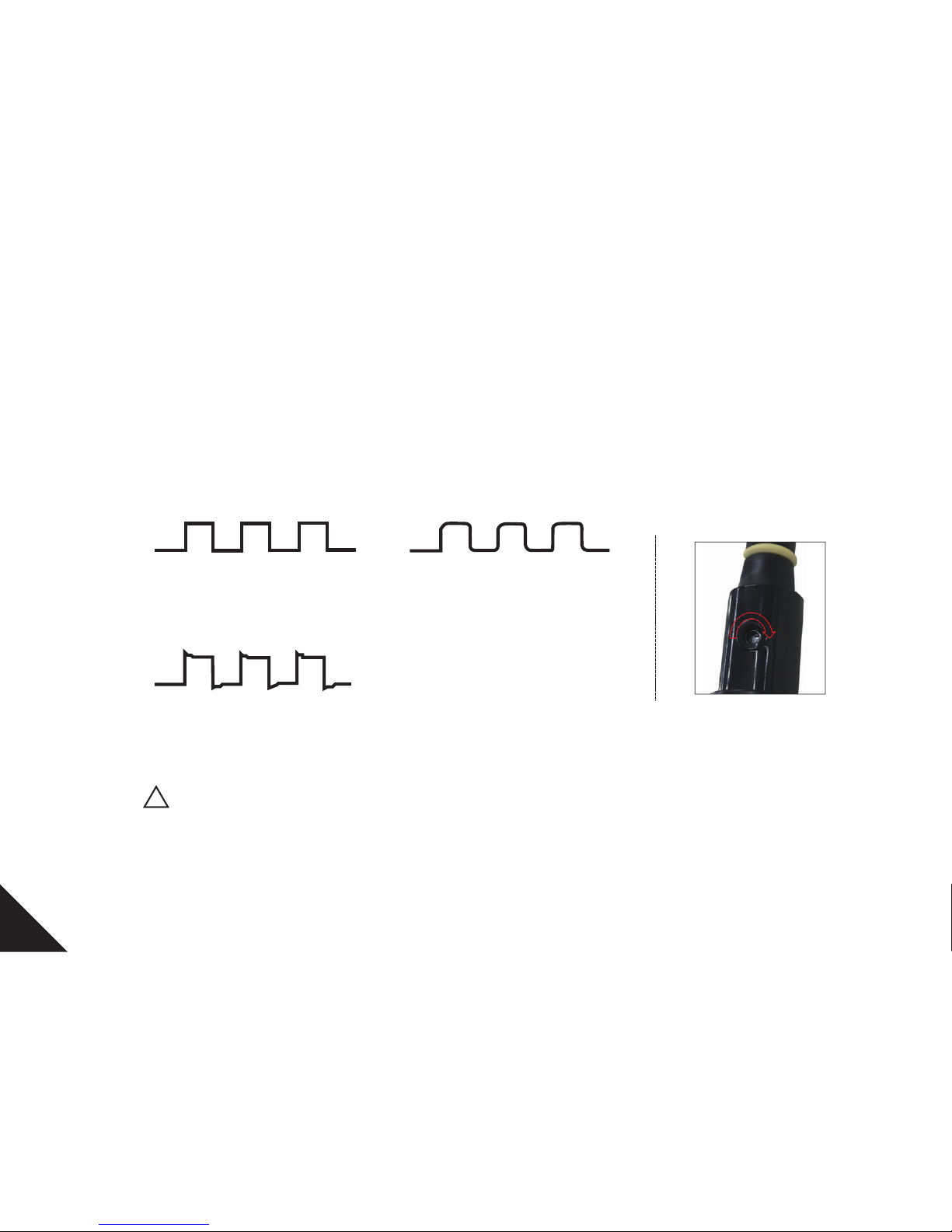
4.5 Probe compensation
Whenever you attach a passive probe(suggest to using standard accessories) for the first time to any input channel, compensate the
probe to match it to the corresponding oscilloscope input channel.
Follow the steps to properly compensate your passive probe(eg. channel 1 compensation)
1) Con nect th e oscillos cope pr obe to ch annel 1, mak e sure pr obe in go od contact .
2) Con nect th e probe to the c alibr ation o utput sign al and th e probe g round to the g round t ermin al.
Prop erly co mpensate d
Unde r compe nsated
Over c ompen sated
3) If necessary, connect probe to other channels. Repeat as needed.
WARNING
To avoid high voltage shock, please ensure that the probe insulation wire intact.
When using the probe keep your finger behind the safety ring to prevent electric shock.
Do not touch the probe head metal parts when the probe is connected to a voltage source in case of electrical shock.
Before any measurement, connect the probe ground to the ground.
!
 Loading...