

Page 1
1 / 8
Micsig AC/DC Current Probes
CP2100 Series User Manual
Applies to
CP2100A/CP2100B
Page 2

2 / 8
Safety Precautions
➢
The measuring circuit should be CAT II 600V or below.
➢
Do not measure bare conductor.
➢
Do not touch the conductor under test and the sensor head while
measuring.
➢
Do not operate in wet/damp conditions.
➢
Do not touch the instrument or the object under test with wet hands.
➢
Please use this product within the scope permitted by the terminal.
➢
Please use this product as required.
➢
Please ground the product through the USB power cable.
Page 3
3 / 8
1. Introduction
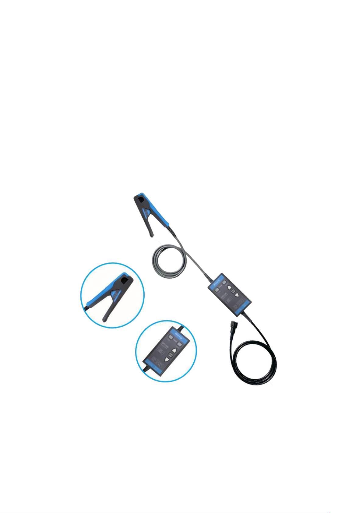
The CP2100 series is a current probe that can measure both DC and AC. It is
a split-type design that is small and beautiful. It uses a standard BNC
interface for oscilloscopes or a multi-connector for adapters. The maximum
current that can be measured is 100Apk
(70Arms); it is divided into 2 models, CP2100A measurable bandwidth range
is DC~800KHz, CP2100B measurable bandwidth range is DC~2.5MHz,The
CP2100 series current probe has two optional ranges: 10A and 100A . With
automatic and manual zero adjustment, USB power supply, no additional
power supply, making measurement more convenient. Often used in motor
drive, power frequency, inverter, power supply, avionics and other fields.
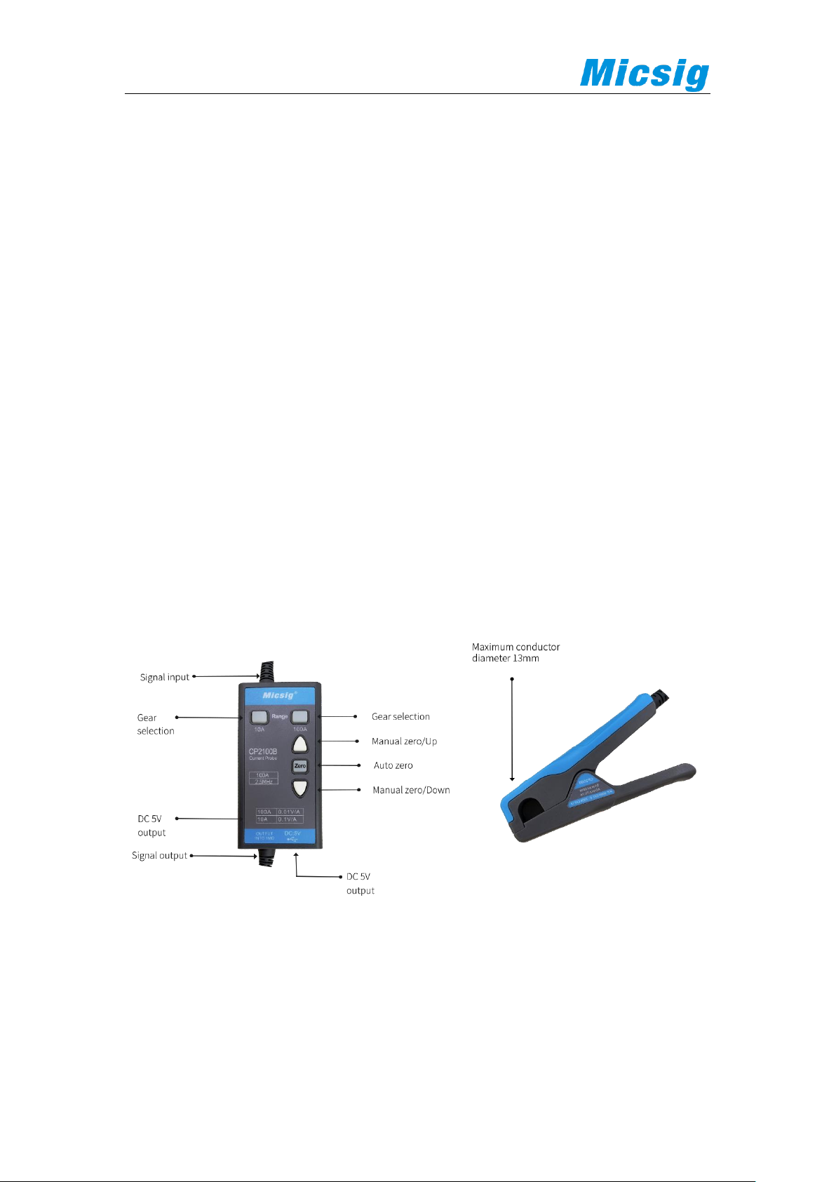
2. Appearance
Page 4
4 / 8
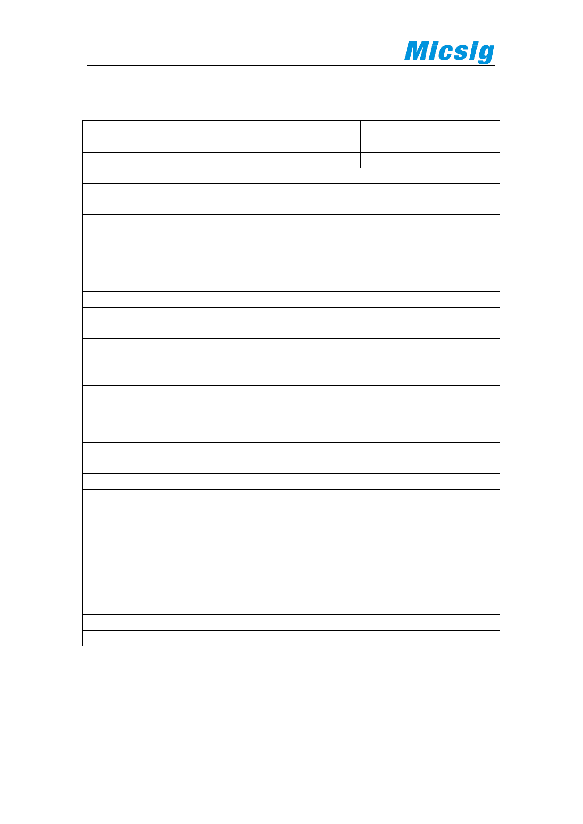
2. Specifications
Parameter
CP2100A
CP2100B
Bandwidth
DC~800KHz
DC~2.5MHz
Rise time
≤583ns
≤175ns
Ranges
10A/100A
Output sensitivity
0.1V/A (10A)
0.01V/A (100A)
DC accuarcy(typical)
3%±50mA (10A)
4%±50mA (100A, 500mA~40Apk)
15% (100A, 40Apk~100Apk)
Signal delay
<150ns (10A)
<200ns (100A)
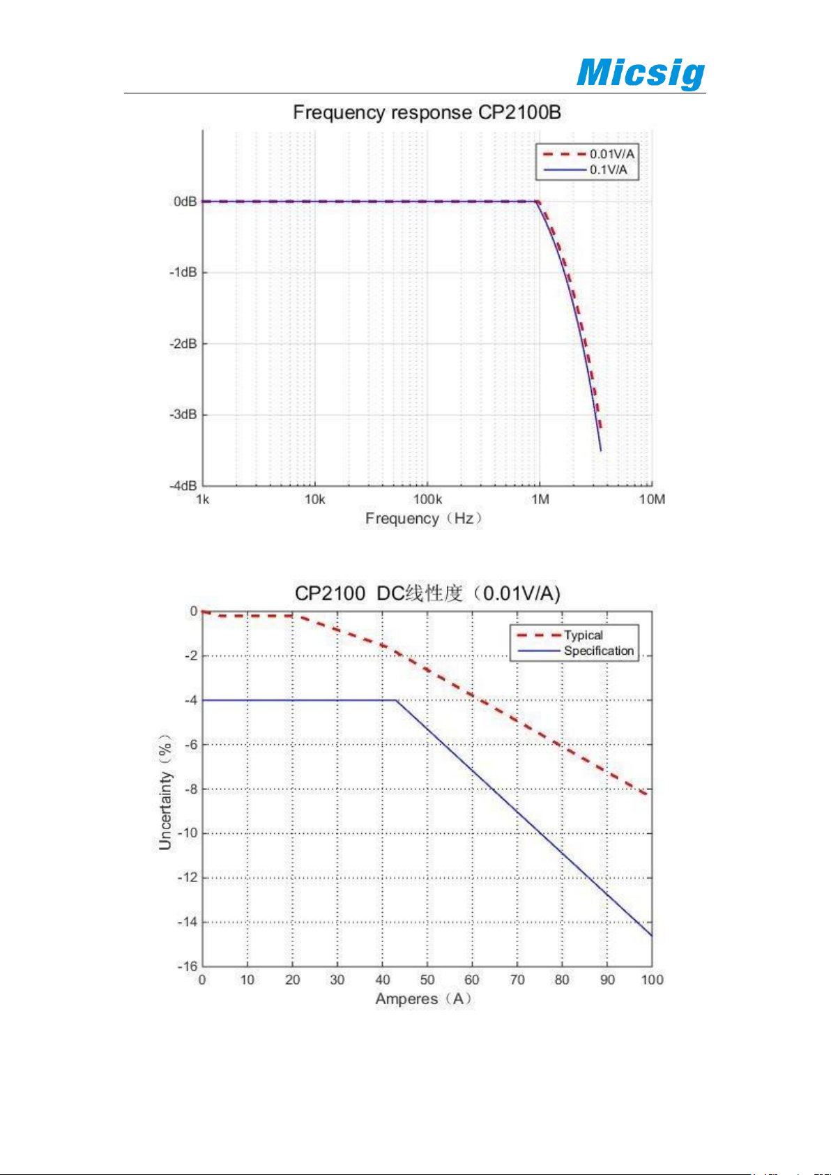
DC signal linearity (typical)
DC signal linearity, typical on page 6
Measuring range
50mA~10Apk (10A)
1A~100Apk (100A)
Maximum measurable
current
100Apk, 70.7Arms (DC+ACpk)
200Apk-pk, 70.7Arms (AC)
Maximum working voltage
CAT III 300V CAT II 600V
Maximum float voltage
CAT III 300V CAT II 600V
Maximum conductor
diameter
13mm
Overload indication
The buzzer beeping, the button light flashing
Power supply
DC 5V
Probe head size
11*6.1*2.5cm
Control box size
10.8*5.6*2.6cm
Length
228cm
Weight
290g
Single package weight
1000g
Single package size
29.5*23.6*5.7cm
Operating Temperature
0°C ~50°C
Storage Temperature
-20°C ~80°C
Operating Humidity
5%~95% (0°C ~40°C , No condensation)
5%~65% (40°C ~50°C , No condensation)
Operating Altitude
≤3000m
Storage Altitude
≤12000m
Page 5
5 / 8
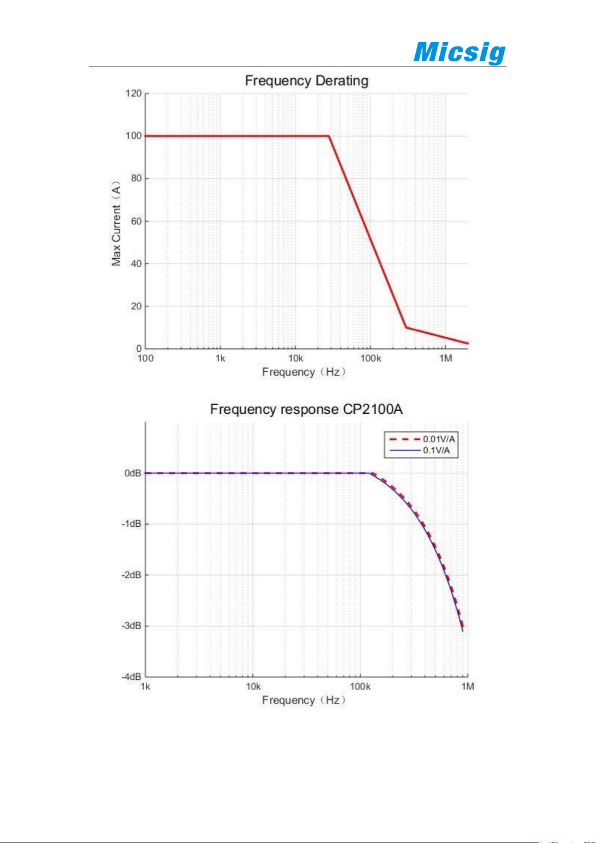
Maximum current versus frequency
Amplitude-frequency characteristic curve -CP2100A
Page 6
6 / 8
Amplitude-frequency characteristic curve -CP2100B
DC signal linearity
Page 7

7 / 8
3. Instructions:
1.Connect the BNC of the current probe to the oscilloscope (or other instrument)
and connect the USB cable to power the current probe.
2.According to the current, select the appropriate range on the probe, the
corresponding button light turns green.
3.Adjust the oscilloscope settings: input impedance 1MΩ; Select current or
set display unit as A; Set the probe attenuation multiplier of the corresponding
channel. If the probe is 100A(0.01V/A), the oscilloscope should be 100X, if
the probe is 10A(0.1V/A), oscilloscope is 10X.
4.Press the auto zero button to realize the auto zero adjustment of the
probe. After the zero adjustment is successful, the buzzer will beep for
once. Otherwise, the “beep” sound will be 3, indicating that the zero
adjustment fails; The external magnetic field may have a slight influence
on the DC zero of the probe. After the zero adjustment is completed,
please do not move it in a large range.
5. Open the clamp of the current probe to clamp the conductor under test
according to the direction indicated by the clamp head. Note: If the
measured current flow direction is opposite to the direction indicated by
the clamp head, the output is negative.
6. Adjust the oscilloscope to get the best waveform.
Note: When the current exceeds the range, the buzzer will sound for a long
time and the button light will flash.
5. Maintenance
During the product warranty period and under normal use, the company
will be responsible for free maintenance due to the failure of the product
itself due to quality problems.
Please keep the product as dry, clean and tidy. If there is dirt, use a soft
cloth or sponge with alcohol to remove dirt. Do not use water.
In order to ensure the performance of the product, it is recommended to
conduct an inspection or calibration once a year.
Page 8

8 / 8
Version
Modify content
release time
1.0
First release
2019.05
The information provided in this document is provided on an "as is" basis
and is subject to change without notice in future editions. Further, Micsig
disclaims all warranties, either express or implied, with respect to this
manual and any information contained herein, including but not limited to
the implied warranties of merchantability and fitness for a particular
purpose, to the fullest extent permitted by applicable law. Micsig is not
responsible for errors or accidental or consequential damages resulting
from the furnishing, use, or use of this document or any information
contained herein. In the event that a separate written agreement between
Micsig and the user contains a warranty term covering the contents of this
document, but the warranty terms conflict with those terms, the warranty
terms in the separate agreement shall prevail.
Shenzhen Micsig Instruments Co.,Ltd.
Add:305 Block A, CLOU Building, Baoshen RD, North Area,
Nanshan Science&Technology Park, Shenzhen, Guangdong,
China, 518000
 Loading...