

Micsig DP5013, DP10013 User Manual
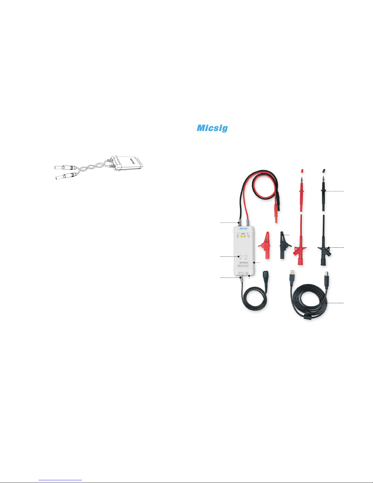
①
②
③
④
⑤
⑥
⑦
⑧
⑨
High Voltage Differential Probe
User Manual
DP5013/DP10 013
Warranty
5
Micsig warr ant s that th is probe wil l be free from def ect s in mate ria ls and
workmanship for a per iod of one (1) yea r an d acces sor ies for a period of
si x( 6) mon th s fr om t he d at e of s hipment. If any such product pr ov es
defective during this warranty period, Micsig, at its option, either will repair
the d efe ctive product without charge f or pa rts and labor, or will provide a
re pl ac em en t in e xc ha ng e fo r th e defe ct iv e pr od uc t. P ar ts , mo du le s
and replacemen t pr oducts used by Mics ig f or warranty wor k ma y be new
or recondi tioned to like new performance. Al l replaced parts, modules and
products become the prop erty of Mics ig.
She nzh en Micsig Inst rum ent s Co., Ltd.
Add: 305 Block A, CLOU Building , Baoshen RD, North Area, Nanshan
Scien ce & Tec hnolo gy Park , Sh enzhe n, Guan gd ong, Ch ina. 51 80 00
WEB: www.mi csi g.com
TEL: +86- 755-88600880
E-mail: sales@micsig.c om
Best Prac ti ce s:
2) Extending the input leads may introduce more noise during measu rement.
If extr a exten si on lead i s neces sa ry, pl ease ensure the extension leads
ar e of eq ua l lengt h an d the i np ut si gn al f requency is un der 10 MH z.
Other wise, m ea surem ent err or s may occ ur.
3) While m easur ing a high fr equen cy s ig na l, do n' t to uch t he end of t he
input l ead wit h yo ur hand or other objects. Otherwise, it may affect the
accur acy of th e me asure ment.
4) Ensure tha t you use an oscilloscope with an inpu t impedance of at least
1MΩ and b andwi dt h of at lea st 100M Hz .
5) Turn on the o sc illos cope or externally powered instrum ent and let the
probe a nd equi pm ent war m up for 20 m in utes.
4
Please re ad this manua l ca reful ly b ef ore use !
①Signa l Input ②P ow er Outp ut ③Powe r In put ④Sig nal Out pu t
⑤Atten uatio n Ra nge But tons/ In dicat ors(O ve r-r ange if f la shing )
⑥Allig ator Cl ip s (red &b lack, 1 p ai r) ⑦Tes t Probe s (r ed & blac k, 1 pair )
⑧Test H ooks (r ed & b lack, 1 p air) ⑨US B Ca ble
1) Twistin g the inp ut l eads to gethe r ca n help re duce no is e and imp rove
the pro be's hi gh f reque ncy res po nse whe n measu ri ng sign als. Pl ea se
view th e diagr am b elow fo r an exam pl e:

3
Spe cif ica tion
Model
DP5013 DP10013
Bandwidth
50MHz 100MHz
Rise Time
7ns
3.5ns
Range Selection
(Attenuation Rate)
50X
500X
50X
500X
Accuracy
±2% ±2%
Maximum Differential
Test Voltage
(DC+ACPK-PK)
130V(50X)
1300V(500X)
130V(50X)
1300V(500X)
Maximum Input
Common Mode Voltage
(DC+ACPK-PK)
130V(50X)
1300V(500X)
130V(50X)
1300V(500X)
CMRR
>80dB( DC)
>60dB(100KHz)
>50dB(1MHz)
>80dB( DC)
>60dB(100KHz)
>50dB(1MHz)
Input Impedance
10MΩ/1pF(differential)
5MΩ/2pF (Single -ended
to ground)
10MΩ/1pF(differential)
5MΩ/2pF (Single -ended
to ground)
Output Voltage
≤3V ≤3V
Overrange Alarm
Button light flashes
Button light flashes
Power Supply
DC 5V,USB Supply
Power
0.85W 0.85W
Dimension
14.5cm*6cm*2.7cm 14.5cm*6cm*2.7cm
Input Cable length
Approx 60cm Approx 60cm
Output Cable length
Approx 90cm Approx 90cm
Operating Temperature 0℃~40℃ 0℃~40℃
Operating Humidity
10%~85% RH 10%~85% RH
Storage Temperature
-30~70℃ -30~70℃
Storage Humidity 5%~90% RH 5%~90% RH
Intro du ction
The Mic sig DP serie s of high vol tage di ffere ntial probes a re design ed f or
th e safe me as ur em en t of hi gh vo lt ag e and f lo at in g v ol tag e s ign al s. Two
model s with 50 MH z and 100 MHz ban dw idth are availabl e, each capable of
two di fferent attenuat ion range s: 500 X for a maximum test voltage of 1300V
and 50X f or amax im um test v oltag e of 1 30V.
Making Me as urement s
1) Pow ering t he p rob e:
Conne ct the USB in put of the probe to the USB port of th e osci llo scope
or a suit able US B po wer sou rce.
2) Con necti ng t he probe to th e os cillo scope :
Conne ct the prob e outpu t BNC to the os cillo scope c ha nnel in put.
Note: m ake sur e th e oscil losco pe i s prope rly gro un ded if ne cessa ry.
3) Set the appropriate attenuation range according to the measured voltage.
4) Con necti ng t he inpu t to the de vi ce unde r tes t:
Usin g the app ro priat e input a cc essor y, con ne ct the pr obe to the device
under t est to st ar t the mea surem en t. I f the a tt en ua ti on ran ge i ndica tor
fl as he s ( in di ca ti ng over- range), p le as e i mme di ate ly dis co nne ct the
power a nd inpu t.
5) Set the measuring instrument.
1
2
General U sa ge S ummary
Conne cting t he p rob e: First, c onnec t the pro be 's USB po wer input t o a USB
power s ource s uc h as the os cil loscope's USB port an d conn ect the probe's BNC
conne ctor to a n os cillo scope i np ut. Then, se t the p ro pe r atten ua ti on rate a nd
conne ct the pr ob e input t o the dev ic e under t est.
Disco nnect in g the pro be: Fir st, dis connect t he prob e input s fr om the de vice
under t est, an d th en unpl ug the pr ob e outpu t and pow er i nput.
Use pro per grou nd ing: To a vo id a n e le ct ri c shock, al l dev ic es t ha t r eq ui re
groun ding mu st b e conne cted to e ar th grou nd. Bef or e ma ki ng conn ec ti on s to
th e input o r output te rm in al s o f th e pro be , en sure th at the te st in str um ent i s
prope rly gro un ded if ne cessa ry.
Measu rem en t safet y: Alway s be awar e of the volt age rat ing of the pr obe and
the mea surem en t acces sorie s yo u are usi ng and of t he m aximu m amplitude of
th e signal yo u intend to mea su re. Ne ver ap pl y a po ten tia l t ha t exce eds th e
vo lta ge rat in gs o f t he pr obe an d/o r i ts acc es sor ies to a vo id d amag i ng t he
produ ct and cr ea ting a ha zardo us s ituat ion.
Only qu alifi ed p erson nel sho ul d perfo rm serv ic e on this p rod uc t.
Do not to uch exp os ed co nnections and components when power is present .
If an over-range condi tio n occu rs, pleas e discon nect power and signal input
fro m th e pro be imme di ately.
Do Not Op erate i n an E xplos ive Atmo sp here.
Do Not Op erate i n Wet/Da mp Cond it ions.
Keep Produ ct S urfac es Clea n an d Dry.
DC 5V,USB Supply
6) When a substantial change in tem perature or oth er cir cum stances affec t
the acc uracy o f th e probe 's zero p oi nt, a calib rat ion is neede d: short the
input terminals of the prob e, the n powe r the probe while si multaneously
press ing the 5 0X a nd 500X k eys for t hr ee seco nds.
 Loading...