

Micsig DP10013, DP20003 User Manual
Best Practices:
5
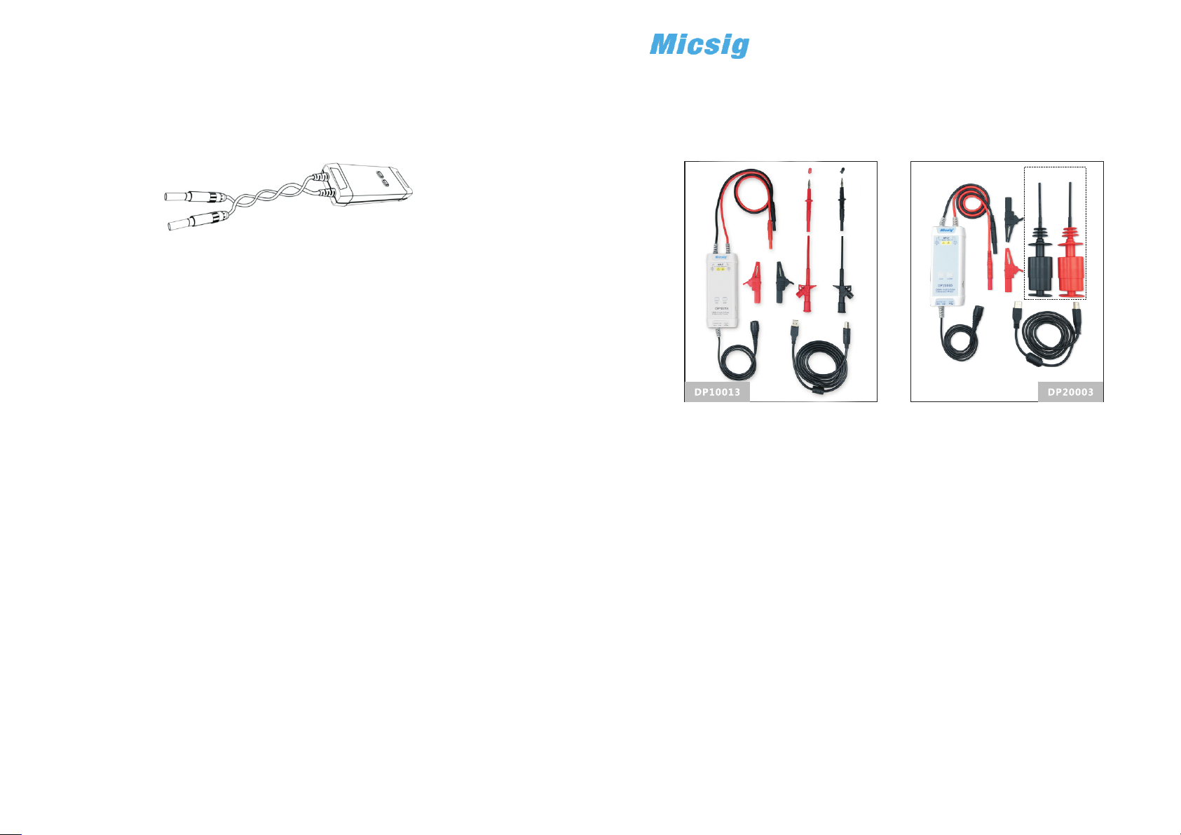
1) Twisting the input leads togeth er can hel p reduce noise a nd improve
th e probe's high f requency resp onse when measuring signals. Please
view the diagram below for an example:
2) Extending the input leads may introduce more noise during measurement.
If extra extension lead is necessary, please ensure the extension leads
ar e of eq ua l length and the input signal frequency is under 10MHz.
Otherwise, measurement errors may occur.
3) While measuring a high frequency signal, don't touch the end of the
input lead with your hand or other objects. Otherwise, it may aff ec t
the accuracy of the measurement.
4) E nsure that you use an oscillo sc op e with an input imp edanc e o f at
least 1MΩ and bandwidth of at least 100MHz.
5) Turn on the oscillos co pe or e xt ernally power ed instrument and let
the probe and equipment warm up for 20 minutes.
6) When a substantial change in temperature or other circumstances affect
the accuracy of the probe's zero point, a calibration is needed: short the
input terminals of the probe, then power the probe while simultaneously
pressing the 50X(200X) and 500X(2000X) keys for three seconds.
DP10013/DP20003
High Voltage Differential Probe
User Manual
Gift
General Usage Summary
Connecting the probe: First, connect the probe's USB power input to a USB
power source such as the oscilloscope's USB port and connect the probe's BNC
connector to an oscilloscope input. Then , se t the proper attenuation rate and
connect the probe input to the device under test.
Warranty
6
Micsig warrants that this probe will be free from defects in materials and
workmanship for a period of one (1) year and accessories for a period of
si x(6) months from the date of shipment . If a ny s uc h product proves
defective during this warranty period, Micsig, at its option, either will repair
the defective product without charge for parts and labor, or will provide a
re placement in exc hange fo r th e defe ct iv e pr od uc t. Par ts , mo du le s
and replacement products used by Micsig for warranty work may be new
or reconditioned to like new performance. All replaced parts, modules and
products become the property of Micsig.
Shenzhen Micsig Instruments Co., Ltd.
Add: 305 Block A, CLOU B uilding, Baos hen RD, No rth Ar ea, Nan shan
Science & Technology Park , Shenzhen, Gua ngdong, China. 518000
WEB: www.micsig.com
TEL: +86-755-88600880
E-mail: sales@micsig.com
Disconnecting the probe: First, disconnect the probe inputs from the devic e
under test, and then unplug the probe output and power input.
Use proper grounding: To avoid an electric shock, all de vi ce s t ha t req ui re
grounding must be connected to earth ground. Before making co nn ections to
the input or o utput termi nals of the probe, ensure that the test instrument is
properly grounded if necessary.
Measurement safety: Always be aware of the voltage rating of the prob e an d
the measurement accessories you are using and of the maximum amplitude of
the signal you intend to measure. Never apply a potential th at exc eeds t he
vo ltage r at ings of th e pro be and/ or its accesso ri es to a voi d dam agin g th e
product and creating a hazardous situation.
Only qualified personnel should perform service on this product.
Do not touch exposed connections and components when power is present.
If an over-range condition occurs, please disconnect power and signal input
from the probe immediately.
Do Not Operate in an Explosive Atmosphere.
Do Not Operate in Wet/Damp Conditions.
Keep Product Surfaces Clean and Dry.
Please read this manual carefully before use!
Introduction
1
The Micsig DP series of high voltage differential probes are designed for
the sa fe measuremen t of high voltag e and floa ting voltage signals. Tw o
models with 100MHz bandwidth are available, each capable of two different
attenuation ranges: 500X(2000X) for a maximum te st voltage of 1300V
(5600V) and 50X(200X) for amaximum test voltage of 130V(560V).
2
Specification
Model
Bandwidth
Rise Time
Attenuation
Gain accurecy
Maximum Differential
Test Voltage
(DC+AC PK-PK)
Maximum input
common mode voltage
Input referred noise
Common Mode
Rejection Ratio
Input Impedance
Output Voltage
Overrange Alarm
Power Supply
Power
Dimension
Input cable length
Output cable length
Operating
Temperature
Operating Humidity
DP10013
100MHz
3.5ns
50X
500X
±2%
130V (50X)
1300V (500X)
CAT 1000V
II
≤40mVrms(50X)
≤230 mVrms(500X)
>80dB(DC)
>60dB(100KHz)
>50dB(1MHz)
10MΩ/1pF(differential)
5MΩ/2pF(single-ended
to ground)
≤3V
Button light flashes
DC 5V,USB Supply
0.85W
14.5cm*6cm*2.7cm
Approx 45cm
Approx 90cm
0℃~40℃
10%~85% RH
DP20003
100MHz
3.5ns
200X
2000X
±2%
560V (200X)
5600V (2000X)
CAT 1000V
III
≤160mVrms(200X)
≤920 mVrms(2000X)
>80dB(DC)
>60dB(100KHz)
>50dB(1MHz)
50MΩ/1.25pF( )
25MΩ/2.5pF(si ngle-ended
to ground)
≤3V
Button light flashes
DC 5V,USB S upply
0.85W
14.5cm*6cm*2.7cm
Approx 45cm
Approx 90cm
0℃~40℃
10%~85% RH
differentia l
3
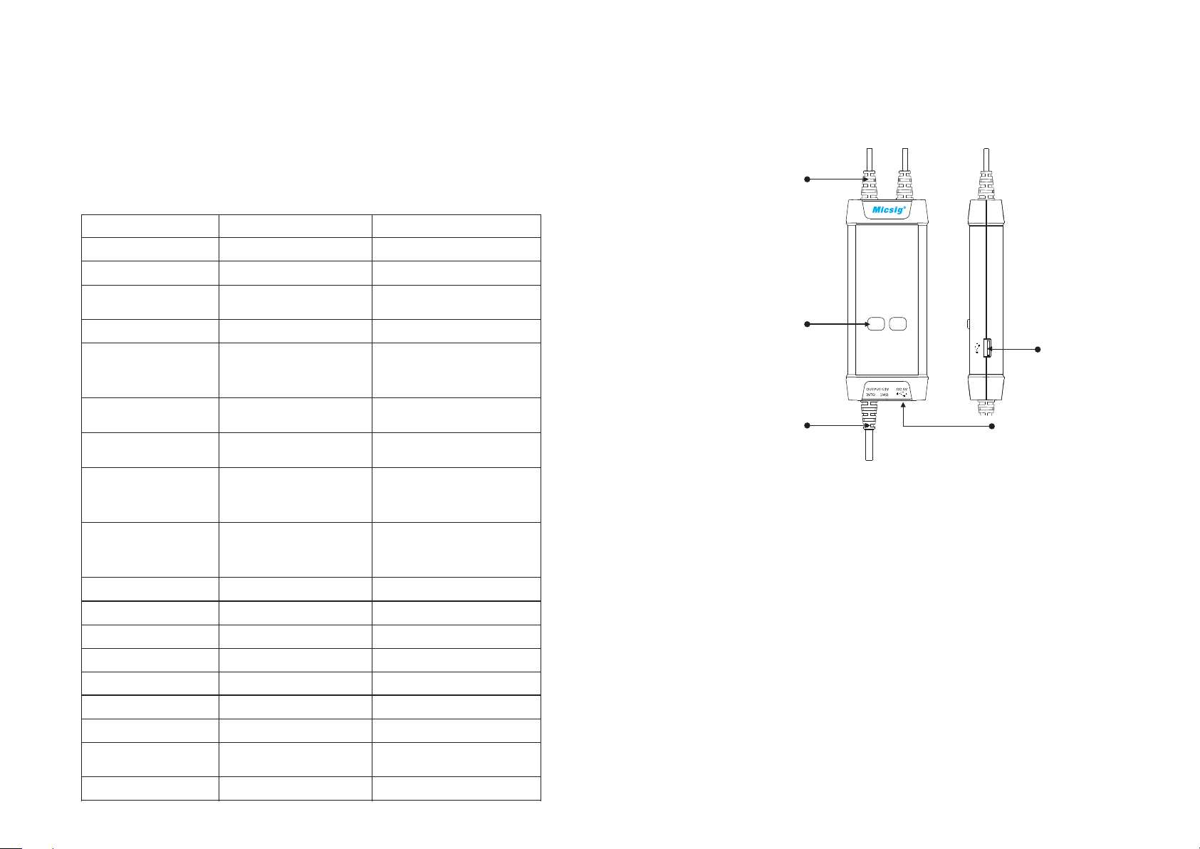
Panel Description
Signal Input
Attenuation Range
Buttons/Indicators
(Over-range if flashing)
Power Output
Signal Output Power Input
Making Measurements
4
1) Powering the probe:
Connect the USB input of the probe to the USB port of the oscilloscope
or a suitable USB power source.
2) Connecting the probe to the oscilloscope:
Connect the probe output BNC to the oscilloscope channel input.
Note: make sure the oscilloscope is properly grounded if necessary.
3) Set the appropriate attenuation r ange accordin g to the measured
voltage.
4) Connecting the input to the device under test:
Using the appropriate input accessory, connect the probe to the device
under test to start the measurement. If the attenuation range ind icator
flashes (indicating over-range), ple as e i mm ediately disconnect t he
power and input.
5) Set the measuring instrument.
 Loading...