

Page 1
Page 2
Version Info
Version
Date
Remarks
V1.0
2023.02
Page 3

Preface
Preface
Dear customers,
Congratulations! Thank you for buying Micsig instrument. Please read this manual carefully before use and
particularly pay attention to the “Safety Precautions”.
If you have read this manual, please keep it properly for future reference.
The information contained herein are furnished in an “as-is” state, and may be subject to change in future versions
without notice.
The standard applicable for this product: GB/T15289-2013.
Page 4

Table of Contents
i
Table of Contents
TABLE OF CONTENTS ........................................................................................................................................................................... I
CHAPTER 1. SAFETY PRECAUTIONS .............................................................................................................................................. 1
1.1 SAFETY PRECAUTIONS ............................................................................................................................................................................................. 1
1.2 SAFETY TERMS AND SYMBOLS ............................................................................................................................................................................... 5
CHAPTER 2. QUICK START GUIDE OF OSCILLOSCOPE ............................................................................................................. 8
2.1 INSPECT PACKAGE CONTENTS ................................................................................................................................................................................ 9
2.2 USE THE BRACKET ................................................................................................................................................................................................ 10
2.3 SIDE PANEL ........................................................................................................................................................................................................... 11
2.4 REAR PANEL .......................................................................................................................................................................................................... 12
2.5 TOP PANEL ............................................................................................................................................................................................................ 13
2.6 FRONT PANEL........................................................................................................................................................................................................ 14
Page 5

ii
2.7 POWER ON/OFF THE OSCILLOSCOPE .................................................................................................................................................................. 15
2.8 UNDERSTAND THE OSCILLOSCOPE DISPLAY INTERFACE .................................................................................................................................. 16
2.9 INTRODUCTION BASIC OPERATIONS OF TOUCH SCREEN ................................................................................................................................. 22
2.10 MOUSE OPERATION ........................................................................................................................................................................................... 24
2.11 CONNECT PROBE TO THE OSCILLOSCOPE ........................................................................................................................................................ 25
2.12 USE AUTO ............................................................................................................................................................................................................ 26
2.13 LOAD FACTORY SETTINGS ................................................................................................................................................................................. 31
2.14 USE AUTO-CALIBRATION ................................................................................................................................................................................... 31
2.15 PASSIVE PROBE COMPENSATION ...................................................................................................................................................................... 33
2.16 MODIFY THE LANGUAGE .................................................................................................................................................................................... 38
CHAPTER 3 AUTOMOTIVE TEST ................................................................................................................................................... 39
3.1 CHARGING/START CIRCUIT ................................................................................................................................................................................. 39
3.1.1 12V Charging ................................................................................................................................................................................................ 41
3.1.2 24V Charging ................................................................................................................................................................................................ 43
Page 6

Table of Contents
iii
3.1.3 Alternator AC Ripple .................................................................................................................................................................................. 44
3.1.4 Ford Focus Smart Generator .................................................................................................................................................................... 46
3.1.5 12V Start ............................................................................................................................................................................................................ 48
3.1.6 24V Start ......................................................................................................................................................................................................... 50
3.1.7 Cranking Current ........................................................................................................................................................................................ 51
3.2 SENSOR TESTS ....................................................................................................................................................................................................... 53
3.2.1 ABS ....................................................................................................................................................................................................................... 54
3.2.2 Accelerator pedal ........................................................................................................................................................................................... 55
3.2.3 Air Flow Meter ................................................................................................................................................................................................ 58
3.2.4 Camshaft ............................................................................................................................................................................................................ 61
3.2.5 Coolant Temperature ................................................................................................................................................................................... 63
3.2.6 Crankshaft ......................................................................................................................................................................................................... 65
3.2.7 Distributor ............................................................................................................................................................................................................ 68
3.2.8 Fuel pressure .................................................................................................................................................................................................... 70
Page 7

iv
3.2.9 Knock ................................................................................................................................................................................................................... 72
3.2.10 Lambda ............................................................................................................................................................................................................ 74
3.2.11 MAP ................................................................................................................................................................................................................... 78
3.2.12 Road Speed ..................................................................................................................................................................................................... 80
3.2.13 Throttle Position.......................................................................................................................................................................................... 82
3.3 ACTUATORS ............................................................................................................................................................................................................ 85
3.3.1 Carbon canister solenoid valve ................................................................................................................................................................ 85
3.3.2 Disel Glow Plugs ............................................................................................................................................................................................. 88
3.3.3 EGR Solenoid Valve ....................................................................................................................................................................................... 90
3.3.4 Fuel Pump ......................................................................................................................................................................................................... 92
3.3.5 Idle speed control valve ............................................................................................................................................................................ 94
3.3.6 Injector (gasoline engine) ....................................................................................................................................................................... 96
3.3.7 Injector (Diesel) .............................................................................................................................................................................................. 98
3.3.8 Pressure regulator ................................................................................................................................................................................... 100
3.3.9 Quantity (Flow) control valve ............................................................................................................................................................... 102
Page 8

Table of Contents
v
3.3.10 Throttle Servo Motor .............................................................................................................................................................................. 104
3.3.11 Variable speed cooling fan ................................................................................................................................................................... 106
3.3.12 Variable valve timing ............................................................................................................................................................................. 109
3.4 IGNITION TESTS .................................................................................................................................................................................................. 111
3.4.1 Primary ........................................................................................................................................................................................................... 112
3.4.2 Secondary ....................................................................................................................................................................................................... 115
3.4.3 Primary + Secondary ................................................................................................................................................................................ 117
3.5 NETWORKS .......................................................................................................................................................................................................... 120
3.5.1 CAN High & CAN Low ................................................................................................................................................................................ 120
3.5.2 LIN Bus ............................................................................................................................................................................................................ 122
3.5.3 FlexRay Bus ................................................................................................................................................................................................... 125
3.5.4 K line ................................................................................................................................................................................................................. 127
3.6 COMBINATION TESTS.......................................................................................................................................................................................... 129
3.6.1 Crankshaft + Camshaft ............................................................................................................................................................................. 129
Page 9

vi
3.6.2 Crankshaft + Primary ignition .............................................................................................................................................................. 131
3.6.3 Primary ignition + Injector voltage.................................................................................................................................................... 133
3.6.4 Crankshaft + Camshaft + Injector + Secondary Ignition .......................................................................................................... 135
CHAPTER 4 HORIZONTAL SYSTEM ............................................................................................................................................ 137
4.1 MOVE THE WAVEFORM HORIZONTALLY....................................................................................................................................................... 139
4.2 ADJUST THE HORIZONTAL TIME BASE (TIME/DIV) .................................................................................................................................... 140
4.3 PAN AND ZOOM SINGLE OR STOPPED ACQUISITIONS ................................................................................................................................. 142
4.4 ROLL, XY .......................................................................................................................................................................................................... 143
4.5 ZOOM MODE .................................................................................................................................................................................................... 152
CHAPTER 5 VERTICAL SYSTEM .................................................................................................................................................. 155
5.1 OPEN/CLOSE WAVEFORM (CHANNEL, MATH, REFERENCE WAVEFORMS)................................................................................................ 157
5.2 ADJUST VERTICAL SENSITIVITY ........................................................................................................................................................................ 162
5.3 ADJUST VERTICAL POSITION ............................................................................................................................................................................. 163
5.4 OPEN CHANNEL MENU ...................................................................................................................................................................................... 163
Page 10

Table of Contents
vii
5.4.1 Set Channel Coupling .................................................................................................................................................................................... 165
5.4.2 Set Bandwidth Limit...................................................................................................................................................................................... 167
5.4.3 Waveform Inversion ...................................................................................................................................................................................... 168
5.4.4 Set Probe Type ................................................................................................................................................................................................. 169
5.4.5 Set Probe Attenuation Coefficient ........................................................................................................................................................... 170
5.4.6 Labels ................................................................................................................................................................................................................... 171
CHAPTER 6 TRIGGER SYSTEM .................................................................................................................................................... 173
6.1 TRIGGER AND TRIGGER ADJUSTMENT .............................................................................................................................................................. 174
6.2 EDGE TRIGGER .................................................................................................................................................................................................... 187
6.3 PULSE WIDTH TRIGGER ..................................................................................................................................................................................... 191
6.4 LOGIC TRIGGER ................................................................................................................................................................................................... 199
6.5 NTH EDGE TRIGGER ........................................................................................................................................................................................... 205
6.6 RUNT TRIGGER .................................................................................................................................................................................................... 208
6.7 SLOPE TRIGGER ................................................................................................................................................................................................... 210
Page 11

viii
6.8 TIMEOUT TRIGGER ............................................................................................................................................................................................. 215
6.9 VIDEO TRIGGER ................................................................................................................................................................................................... 218
6.10 SERIAL BUS TRIGGER....................................................................................................................................................................................... 223
CHAPTER 7 ANALYSIS SYSTEM ................................................................................................................................................... 224
7.1 AUTOMATIC MEASUREMENT ............................................................................................................................................................................. 225
7.2 FREQUENCY METER MEASUREMENT ............................................................................................................................................................... 238
7.3 CURSOR ................................................................................................................................................................................................................ 239
7.4 PHASE RULERS .................................................................................................................................................................................................... 244
CHAPTER 8 SCREEN CAPTURE, MEMORY DEPTH AND WAVEFORM STORAGE .......................................................... 246
8.1 SCREEN CAPTURE FUNCTION ............................................................................................................................................................................ 247
8.2 VIDEO RECORDING ............................................................................................................................................................................................. 250
8.3 WAVEFORM STORAGE ........................................................................................................................................................................................ 251
8.4 OSCILLOSCOPE SETTING SAVE ............................................................................................................................................................................ 258
CHAPTER 9 MATH AND REFERENCE ........................................................................................................................................ 260
Page 12

Table of Contents
ix
9.1 DUAL WAVEFORM CALCULATION ..................................................................................................................................................................... 261
9.2 FFT MEASUREMENT .......................................................................................................................................................................................... 266
9.3 ADVANCED MATH ............................................................................................................................................................................................... 273
9.4 REFERENCE WAVEFORM CALL .......................................................................................................................................................................... 277
CHAPTER 10 DISPLAY SETTINGS............................................................................................................................................... 281
10.1 WAVEFORM SETTINGS ..................................................................................................................................................................................... 283
10.2 GRATICULE SETTING ........................................................................................................................................................................................ 283
10.3 PERSISTENCE SETTING .................................................................................................................................................................................... 284
10.4 HORIZONTAL EXPANSION CENTER ................................................................................................................................................................. 287
10.5 COLOR TEMPERATURE SETTING .................................................................................................................................................................... 287
10.6 TIME BASE MODE SELECTION ........................................................................................................................................................................ 288
CHAPTER 11 SAMPLING SYSTEM .............................................................................................................................................. 289
11.1 SAMPLING OVERVIEW ...................................................................................................................................................................................... 290
11.2 RUN/STOP KEY AND SINGLE SEQ KEY ........................................................................................................................................................ 296
Page 13

x
11.3 SELECT SAMPLING MODE ............................................................................................................................................................................... 297
11.4 RECORD LENGTH AND SAMPLING RATE ........................................................................................................................................................ 303
CHAPTER 12 SERIAL BUS TRIGGER AND DECODE (OPTIONAL) ..................................................................................... 307
12.1 UART (RS232/RS422/RS485) BUS TRIGGER AND DECODE .............................................................................................................. 312
12.2 LIN BUS TRIGGER AND DECODE .................................................................................................................................................................... 324
12.3 CAN BUS TRIGGER AND DECODE .................................................................................................................................................................. 332
12.4 SPI BUS TRIGGER AND DECODE .................................................................................................................................................................... 339
12.5 I2C BUS TRIGGER AND DECODE .................................................................................................................................................................... 346
12.6 ARINC429 BUS TRIGGER AND DECODE...................................................................................................................................................... 354
12.7 1553B BUS TRIGGER AND DECODE.............................................................................................................................................................. 362
CHAPTER 13 HOMEPAGE FUNCTIONS ..................................................................................................................................... 370
13.1 OSCILLOSCOPE (SEE CHAPTERS 2~12) ....................................................................................................................................................... 372
13.2 APP STORE ........................................................................................................................................................................................................ 372
13.3 SETTINGS ........................................................................................................................................................................................................... 376
Page 14

Table of Contents
xi
13.4 FILE MANAGER ................................................................................................................................................................................................. 383
13.5 CALCULATOR ..................................................................................................................................................................................................... 384
13.6 BROWSER .......................................................................................................................................................................................................... 384
13.7 GALLERY ............................................................................................................................................................................................................ 385
13.8 CALENDAR ......................................................................................................................................................................................................... 388
13.9 ELECTRONIC TOOLS ......................................................................................................................................................................................... 388
13.10 CLOCK ............................................................................................................................................................................................................. 389
13.11 POWER OFF .................................................................................................................................................................................................... 392
CHAPTER 14 REMOTE CONTROL ............................................................................................................................................... 395
14.1 HOST COMPUTER ............................................................................................................................................................................................. 396
14.1.1 Installation of Host Computer Software ............................................................................................................................................ 396
14.1.2 Connection of Host Computer................................................................................................................................................................. 397
14.1.3 Main Interface Introduction ................................................................................................................................................................... 399
14.1.4 Operation Interface Introduction ......................................................................................................................................................... 401
Page 15

xii
14.1.5 Storage and View of Pictures and Videos .......................................................................................................................................... 402
14.2 MOBILE REMOTE CONTROL ............................................................................................................................................................................ 404
CHAPTER 15 UPDATE AND UPGRADE FUNCTIONS.............................................................................................................. 408
15.1 SOFTWARE UPDATE ......................................................................................................................................................................................... 409
15.2 ADD OPTIONAL FUNCTIONS ............................................................................................................................................................................ 410
CHAPTER 16 REFERENCE ............................................................................................................................................................. 413
16.1 MEASUREMENT CATEGORY ............................................................................................................................................................................. 414
16.2 POLLUTION DEGREE ........................................................................................................................................................................................ 415
CHAPTER 17 TROUBLESHOOTING ............................................................................................................................................ 417
CHAPTER 18 SERVICES AND SUPPORT .................................................................................................................................... 423
ANNEX ................................................................................................................................................................................................ 425
ANNEX A:MAINTENANCE AND CARE OF OSCILLOSCOPE ....................................................................................................................................... 425
ANNEX B: ACCESSORIES ............................................................................................................................................................................................ 428
Page 16

Chapter 1. Safety Precautions
1
Chapter 1. Safety Precautions
1.1 Safety Precautions
The following safety precautions must be understood to avoid personal injury and prevent damage to this product or
any products connected to it. To avoid possible safety hazards, it is essential to follow these precautions while using
this product.
Only professionally trained personnel can operate the maintenance procedure.
Avoid fire and personal injury.
Use proper power cord. Use only the power cord specified for this product and certified for the country/region
of use.
Connect and disconnect probes properly. Connect the instrument probe correctly, and its ground terminal is
ground phase. Do not connect or disconnect probes or test leads while they are connected to a voltage source.
Page 17

2
Disconnect the probe input and the probe reference lead from the circuit under test before disconnecting the
probe from the measurement product.
Ground the product. To avoid electric shock, the instrument grounding conductor must be connected to
earth ground.
Observe all terminal ratings. To avoid fire or shock hazard, observe all rating and markings on the product.
Consult the product manual for further information of ratings before making connections to the product.
User correct probes. To avoid excessive electric shock, use only correct rated probes for any measurement.
Disconnect AC power. The adapter can be disconnected from AC power and the user must be able to access the
adapter at any time.
Do not operate without covers. Do not operate the product with covers or panels removed.
Do not operate with suspected failures. If you suspect that there is damage to this product, have it inspected
by service personnel designated by Micsig.
Page 18

Chapter 1. Safety Precautions
3
Use adapter correctly. Supply power or charge the equipment by power adapter designated by Micsig, and
charge the battery according to the recommended charging cycle.
Avoid exposed circuitry. Do not touch exposed connections and components when power is present.
Provide proper ventilation.
Do not operate in wet/damp conditions.
Do not operate in a flammable and explosive atmosphere.
Keep product surfaces clean and dry.
The disturbance test of all models complies with Class A standards, based on EN61326:1997+A1+A2+A3,
but do not meet Class B standards.
Measurement Category
The ATO series oscilloscope is intended to be used for measurements in Measurement Category I.
Page 19

4
Measurement Category Definition
Measurement category I is for measurements performed on circuits not directly connected to the MAINS. Examples
are measurements on circuits not derived from MAINS, and specially protected (internal) MAINS derived circuits.
In the latter case, transient stresses are variable; for that reason, the user must understand the transient withstand
capability of the equipment.
Warning
IEC Measurement Category. Under IEC Category I mounting conditions, the input terminal can be connected to the
circuit terminal with a maximum line voltage of 300Vrms. To avoid the risk of electric shock, the input terminal
should not be connected to the circuit with a line voltage greater than 300Vrms. Instantaneous overvoltage is
present in circuits that are isolated from the mains supply. The ATO series digital oscilloscope is designed to safely
withstand sporadic transient overvoltage up to 1000Vpk. Do not use this equipment for any measurements in
circuits where the instantaneous overvoltage exceeds this value.
Page 20

Chapter 1. Safety Precautions
5
1.2 Safety Terms and Symbols
Terms in the manual
These terms may appear in this manual:
Warning. Warning statements indicate conditions or practices that could result in injury or loss of life.
Caution. Caution statements indicate conditions or practices that could result in damage to this product or
other property.
Terms on the product
These terms may appear on the product:
Danger indicates an injury hazard immediately accessible as you read the marking.
Warning indicates an injury hazard not immediately accessible as you read the marking.
Caution indicates a hazard to this product or other properties.
Page 21
6
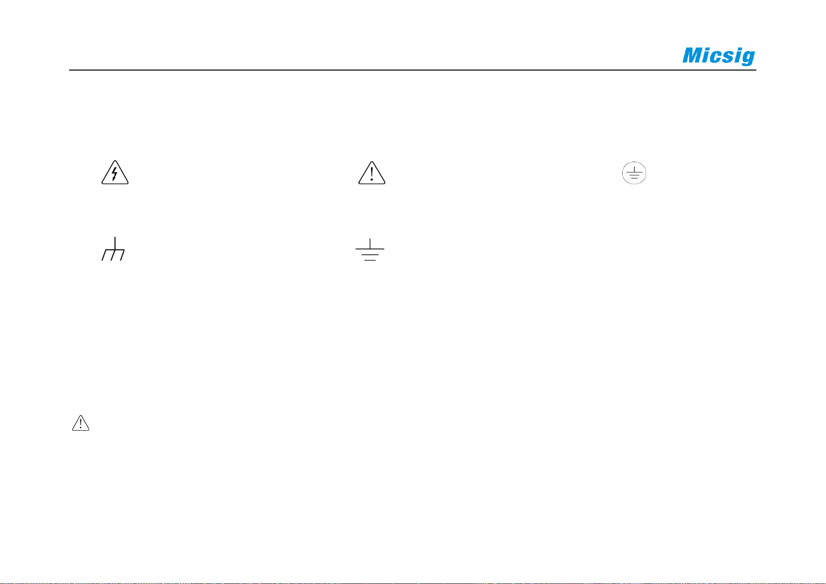
Symbols on the product
The following symbols may appear on the product:
Hazardous Voltage Caution Refer to Manual Protective Ground Terminal
Chassis Ground Measurement Ground Terminal
Please read the following safety precautions to avoid personal injury and prevent damage to this product or
any products connected to it. To avoid possible hazards, this product can only be used within the specified
scope.
Warning
If the instrument input port is connected to a circuit with the peak voltage higher than 42V or the power exceeding
4800VA, to avoid electric shock or fire:
Page 22

Chapter 1. Safety Precautions
7
User only insulated voltage probes supplied with the instrument, or the equivalent product indicated in the
schedule.
Before use, inspect voltage probes, test leads, and accessories for mechanical damage and replace when
damaged.
Remove voltage probes and accessories not in use.
Plug the battery charger into the AC outlet before connecting it to the instrument.
Page 23

8
Chapter 2. Quick Start Guide of Oscilloscope
This chapter contains checks and operations of the oscilloscope. You are recommended to read them carefully to
understand appearance, power on/off, settings and related calibration requirements of the ATO series oscilloscope.
Inspect package contents
Mouse operation
Use bracket
Connect probe to the oscilloscope
Side panel & rear panel
Use automatic
Front panel
Use factory settings
Power on/off the oscilloscope
Use auto-calibration
Understand the oscilloscope display interface
Passive probe compensation
Introduction to basic operations of oscilloscope
Modify the language
Page 24

Chapter 2. Quick Start Guide of Oscilloscope
9
2.1 Inspect Package Contents
When you open package after receipt, please check the instrument according to the following steps.
1) Inspect if there is any damage caused by transportation
If the package or foam is found to be severely damaged, please retain it until the instrument and accessories
pass the electrical and mechanical properties test.
2) Inspect the accessories
A detailed description is given in “Annex B” of this manual. You can refer it to check if the accessories are
complete. If the accessories are missing or damaged, please contact Micsig’s agent or local office.
3) Inspect the instrument
If any damage to oscilloscope is found by the appearance inspection or it fails to pass the performance test,
please contact Micsig’s agent or local office. If the instrument is damaged due to transportation, please retain
the package and contact the transportation company or Micsig’s agent, and Micsig will make arrangement.
Page 25
10
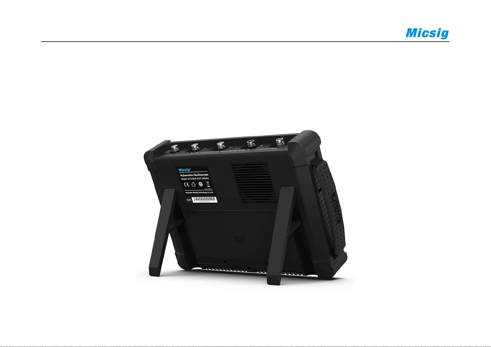
2.2 Use the Bracket
Put the front panel of the oscilloscope flatly on the table. Use your two index fingers to hold the underside of the
bracket and open the bracket by slightly upwards force, as shown in Figure 2-1.
Figure 2-1 Open Bracket
Page 26
Chapter 2. Quick Start Guide of Oscilloscope
11
2.3 Side Panel
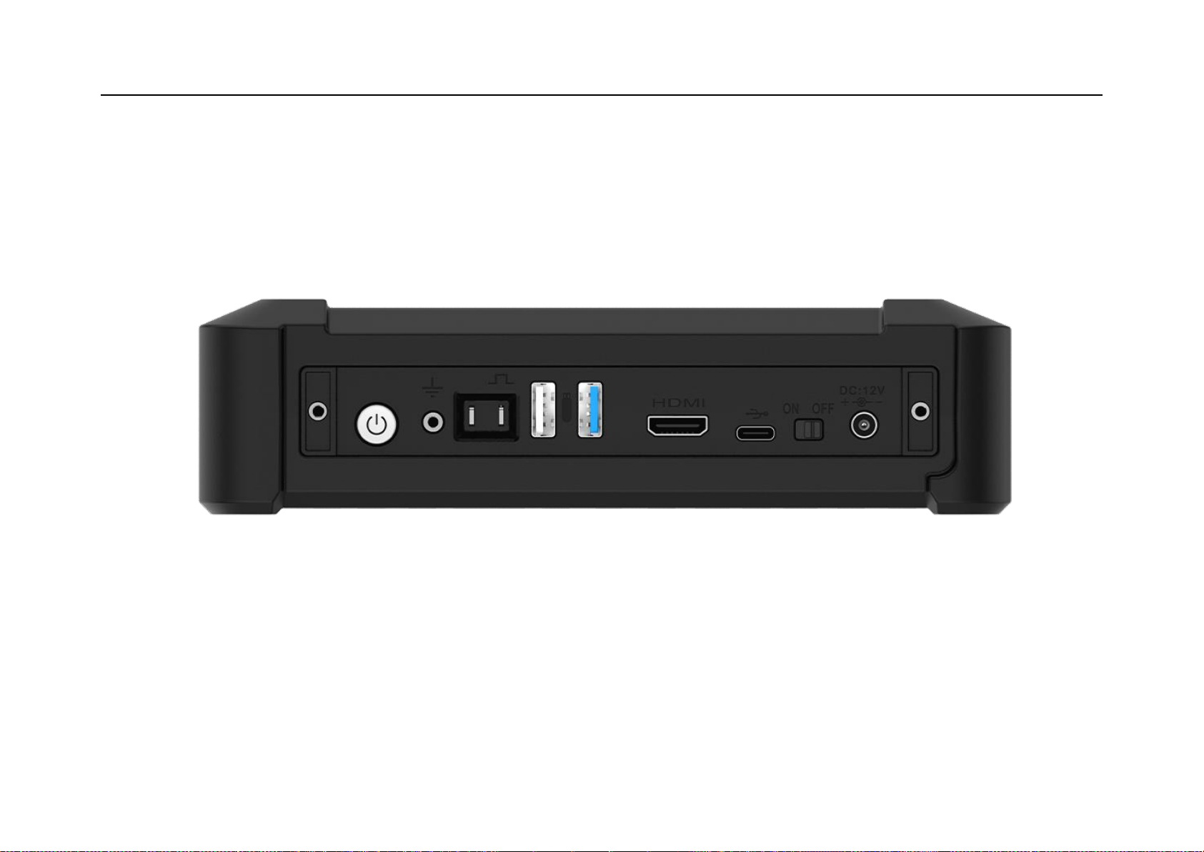
Figure 2-2 Side Panel
There are various interfaces on the side of the oscilloscope, from left to right: Power-on button, Grounding, Probe
compensation signal output, USB Host, HDMI, USB Device, Power-off lock, and Power port.
Page 27
12
2.4 Rear Panel
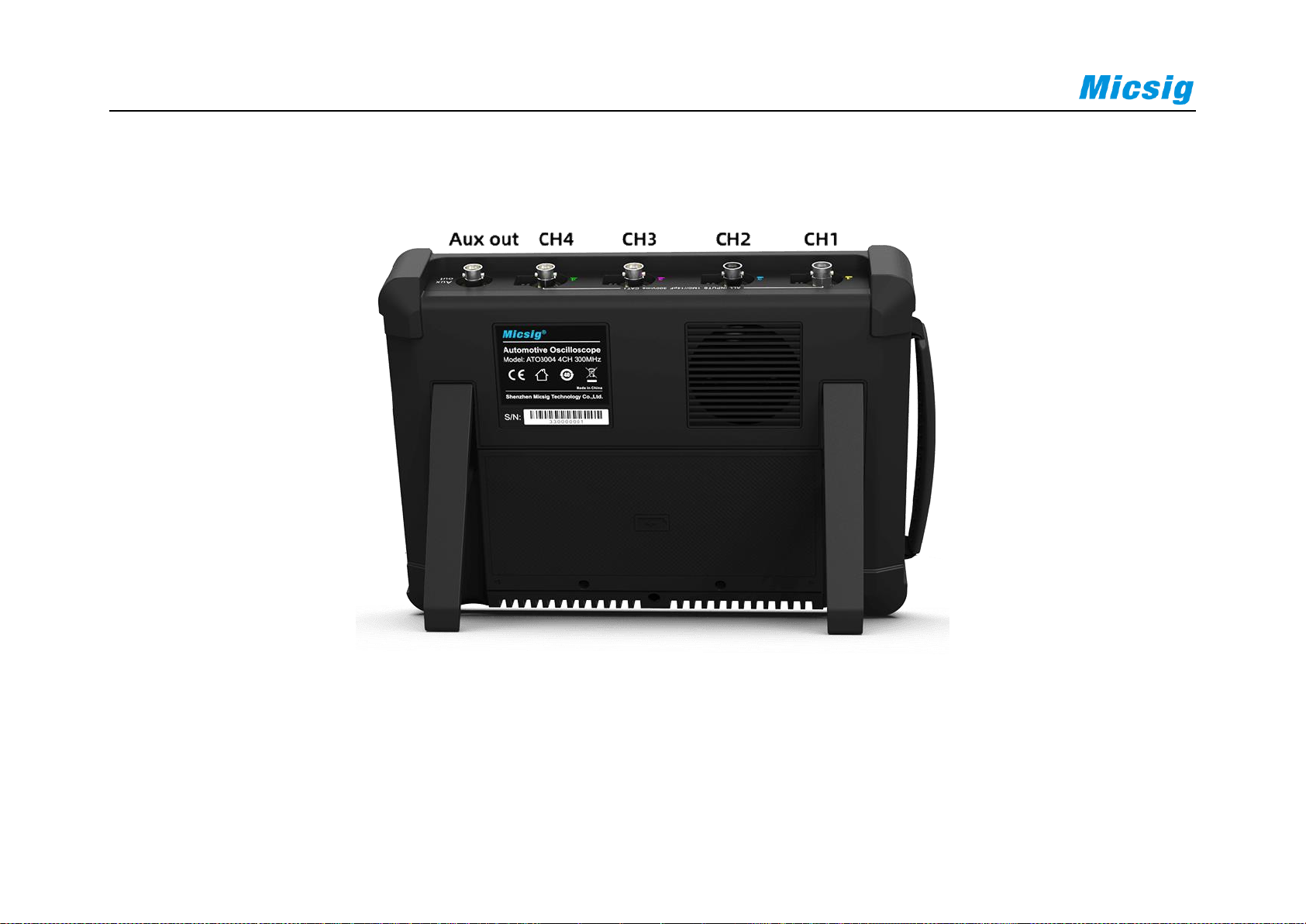
Figure 2-3 Rear Panel
a) Ch1 – Ch4 are signal measurement channels
Page 28
Chapter 2. Quick Start Guide of Oscilloscope
13
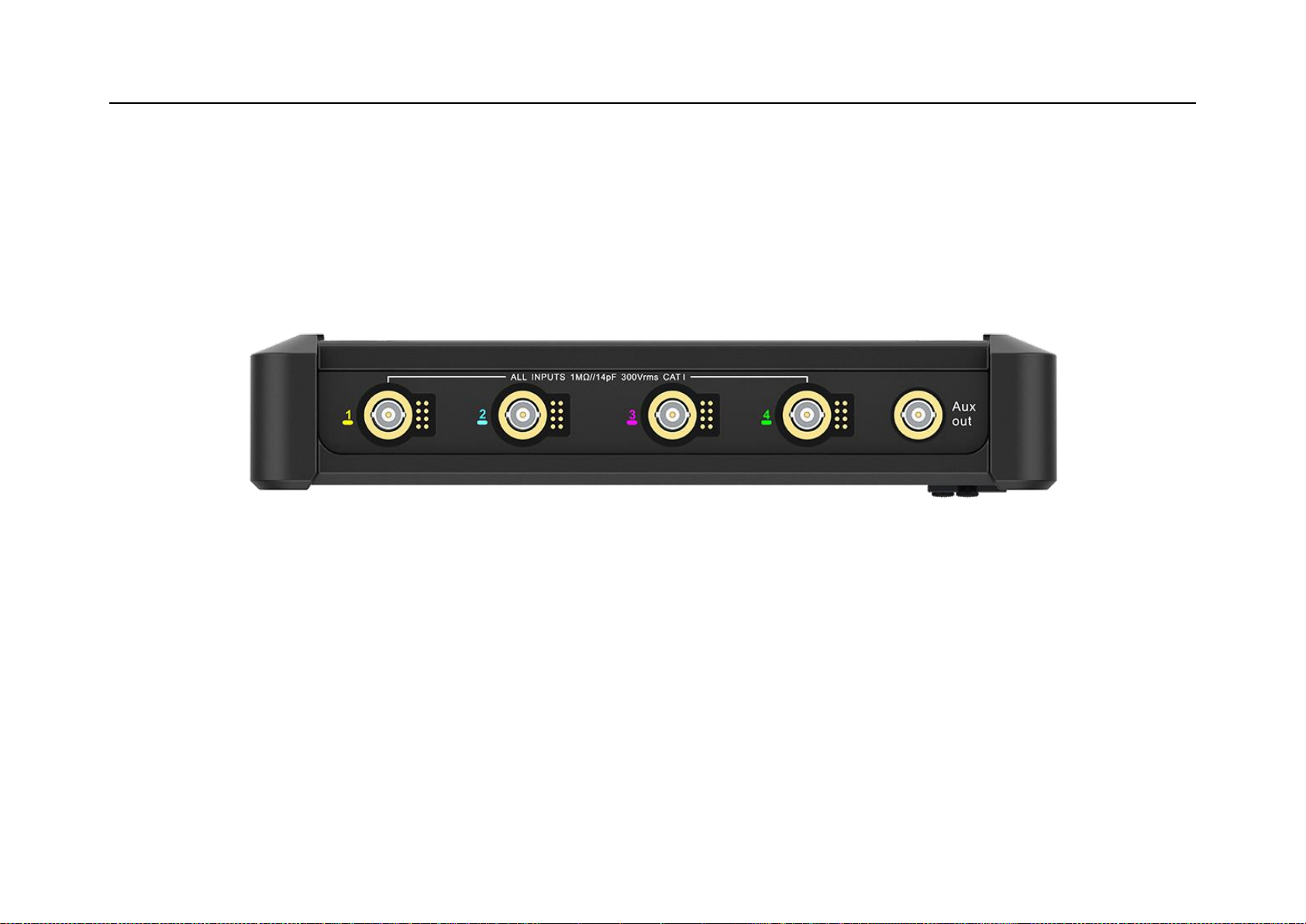
b) Aux out is an auxiliary channel, which is mainly used to measure the waveform refresh rate of the oscilloscope
and cascade the current oscilloscope signal to other oscilloscopes.
2.5 Top Panel
Figure 2-4 Top Panel of Automotive Oscilloscope
On top of the oscilloscope is the Micsig UPI universal probe interface, which is designed to power active probes
and automatically communicate scale factors on the scope display.
Page 29
14
2.6 Front Panel
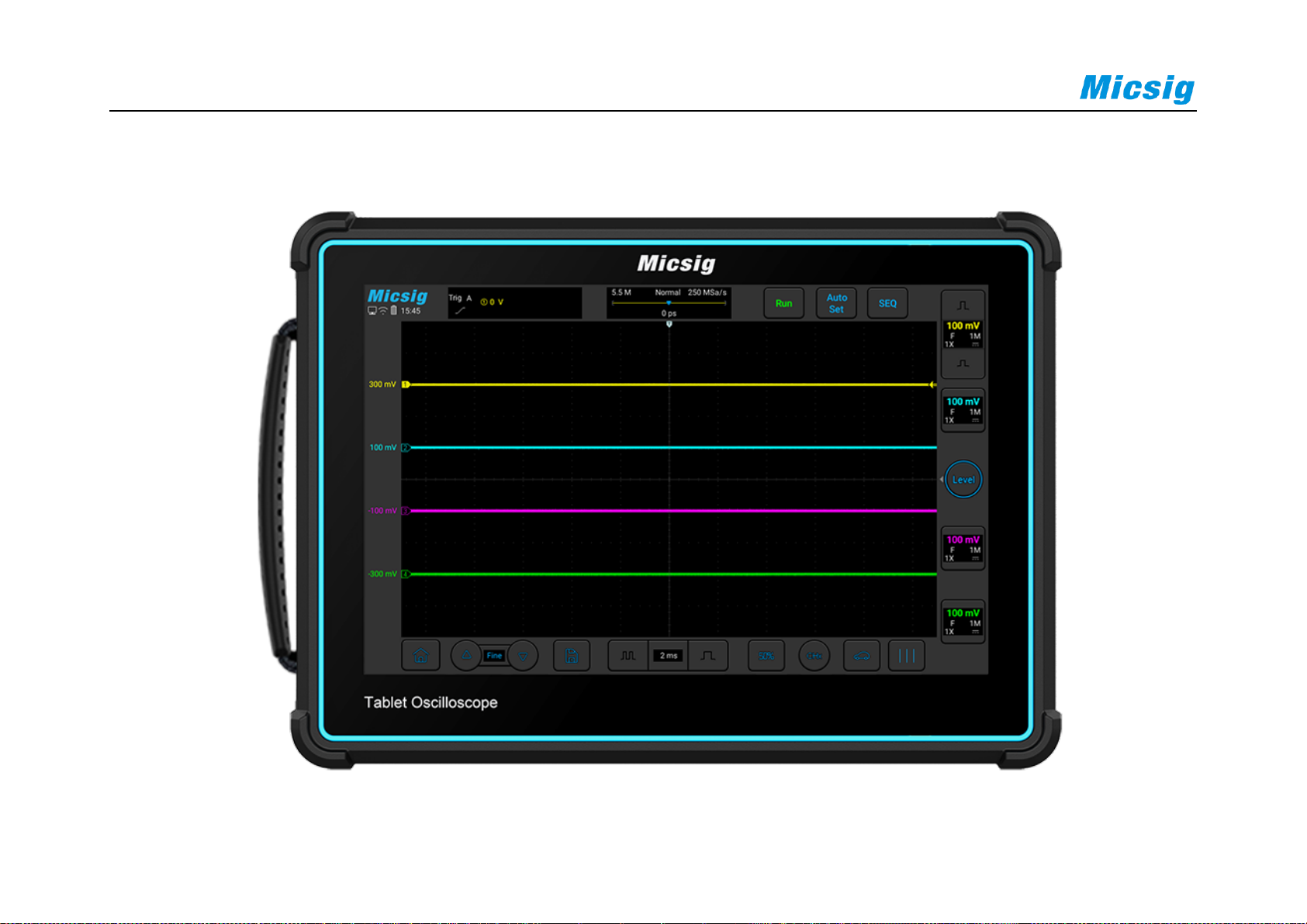
Figure 2-5 Front Panel of Automotive Oscilloscope
Page 30
Chapter 2. Quick Start Guide of Oscilloscope
15
2.7 Power on/off the Oscilloscope
Power on/off the oscilloscope
First time start
Connect power adapter to the oscilloscope, and the oscilloscope should not be pressed on the adapter cable.
Check the Power-off lock on the side of oscilloscope and press the power button to start the instrument.
Power on
Press the power button to start the instrument while ensuring it is connected to a power supply.
Power off
Press the power button , go to power-off interface, and click to turn off the instrument.
Long press the power button for forced power-off of the instrument.
Power-off lock
Page 31
16
Turn the power-off lock switch to OFF, the oscilloscope cannot be turned on.
Caution: Forced power-off may result in loss of unsaved data, please use with caution.
2.8 Understand the Oscilloscope Display Interface
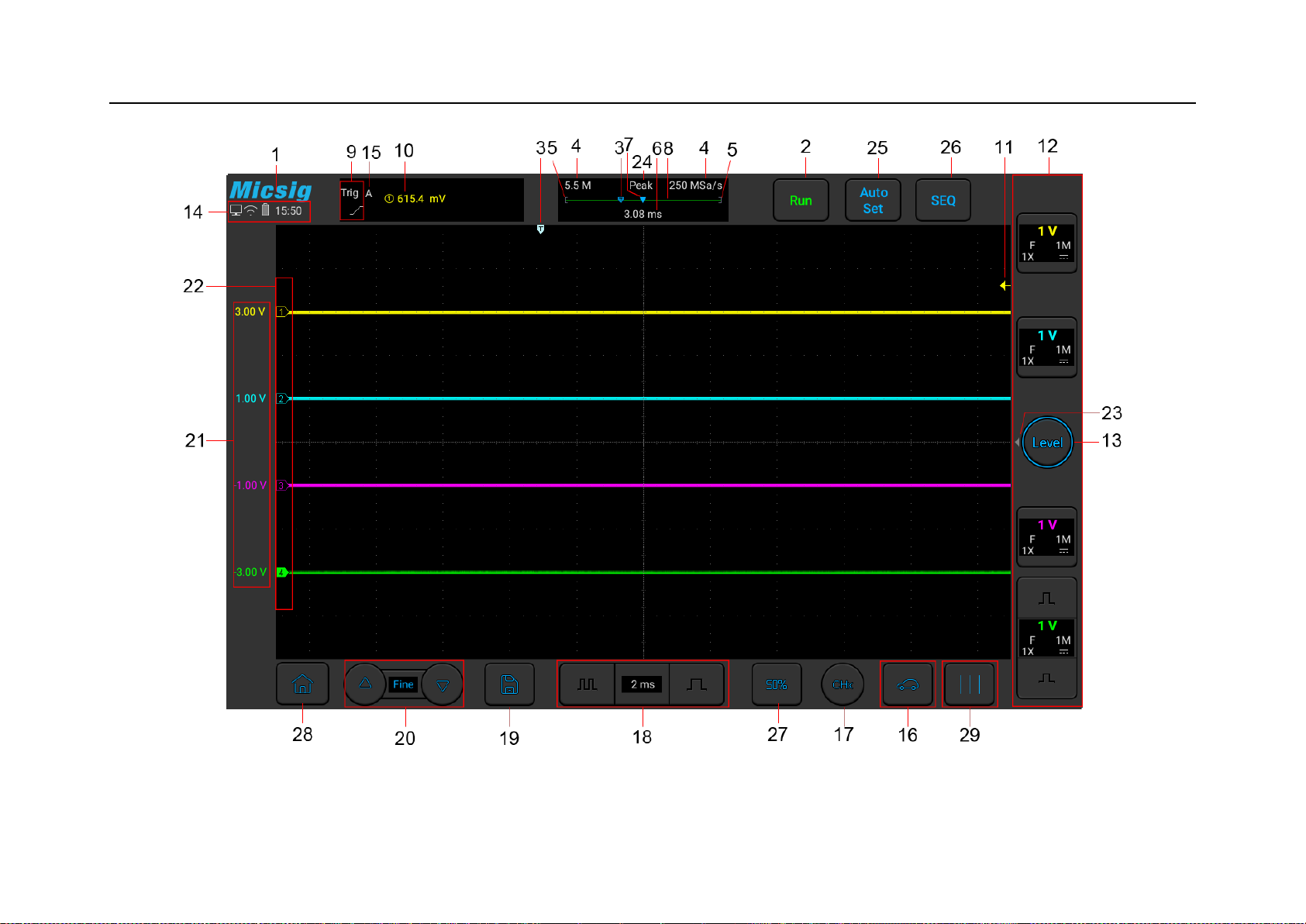
This section provides a brief introduction and description of the ATO series oscilloscope user’s interface. After
reading this section, you can be familiar with the oscilloscope display interface content within the shortest possible
time. The specific settings and adjustments will be detailed in subsequent chapters and sections. The following
items may appear on the screen at a given time but not all items are visible. The oscilloscope interface is shown in
Figure 2-6.
Page 32
Chapter 2. Quick Start Guide of Oscilloscope
17
Figure 2-6 Oscilloscope Interface Display
Page 33
18
No.
Description
1
Micsig logo
2
Oscilloscope status, including RUN, STOP, WAIT, Auto
3
Trigger point
4
Sampling rate, memory depth
5
The area in “[]” indicates the position of waveform displayed on the screen throughout the memory
depth
6
Delay time, the time at which the center line of the waveform display area is relative to the trigger
point
7
Center line of waveform display area
8
Memory depth indicatrix
9
Current trigger type indication
10
Current trigger source, trigger level
Page 34
Chapter 2. Quick Start Guide of Oscilloscope
19
No.
Description
11
Trigger level indicator
12
CH1、CH2、CH3、CH4 channel icons and vertical sensitivity icon. Tap the channel icons to open
channels; Click or to adjust the vertical sensitivity of channels; Open the channel menu by
swipe left from the desired channel and swipe right to close; Display the vertical sensitivity of
channels; Display couple method.
13
Trigger level adjustment, press on the button to modify the trigger level through upward and
downward movements.
14
Display areas of USB-PC connection, USB connection, battery level, time etc.
15
Trigger Mode: A(auto), N(Normal).
16
Automotive diagnostic software presets
17
Current channel selection. Click to pop up the current channel switching menu to switch the current
channel.
Page 35
20
No.
Description
18
Horizontal time base control icon. Tap the left/right time base buttons to adjust the horizontal time
base of the waveform. Tap the time base to open the time base table. Tap to select the desired time
base.
19
Quick save. Tap to quickly save the waveform as a reference waveform.
20
Fine adjustment button. Tap the button to finely adjust the last operation, including waveform
position, trigger level position, trigger point and cursor position.
21
The vertical position value of the channel indicator.
22
Channel indicator can indicate the zero-level position of the open channel.
23
Trigger quick start menu indicator: swipe left to open trigger quick start menu
24
Sample Mode: Normal, Average, Envelope, Peak
25
Auto Set, AutoRange
26
SEQ, Single Sequence Acquisition
Page 36

Chapter 2. Quick Start Guide of Oscilloscope
21
No.
Description
27
50%: Touch to set:
The vertical position of the current channel waveform to the zero point
The horizontal position of the current channel waveform to center of the screen
The trigger level to the center of the trigger channel's waveform
The activecursor back to the center of the scree
28
Home
29
Phase rulers: help to measure the timing of a cyclic waveform on a scope view.
Table 2-1 Description of Oscilloscope Display Interface
Page 37
22
2.9 Introduction Basic Operations of Touch Screen
The ATO series oscilloscope operates mainly by tap, swipe, single-finger drag.
Tap
Tap button on the touch screen to activate the corresponding menu and function. Tap any blank space on the screen
to exit the menu.
Swipe
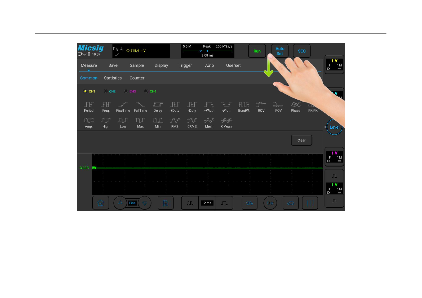
Single-finger swipe: to open/close menus, including main menu, shortcut menu button and other channel menu
operations. For example, the main menu is opened as shown in Figure 2-7. The closing method is the opposite of
the opening method.
Page 38
Chapter 2. Quick Start Guide of Oscilloscope
23
Figure 2-7 Slide out of Main Menu
Tap the options in the main menu to enter the corresponding submenu.
Page 39
24
Single-finger drag
For coarse adjustments of vertical position, trigger point, trigger level, cursor, etc. of the waveform. Refer to “4.1
Horizontal Move Waveform” and “5.3 Adjust Vertical Position” for details.
Pinch
For fine adjustments of vertical sensitivity.
2.10 Mouse Operation
Connect the mouse to the “USB Host” interface, then operate the oscilloscope with the mouse. The left button, right
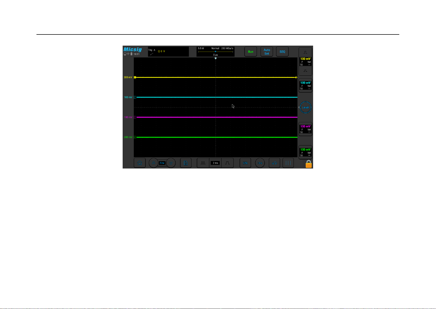
button and scroll wheel of the mouse have the same functions as the finger touch function. Figure 2-8 is a schematic
diagram of the mouse single click to select “Run/Stop” function under the “Menu” option in the “Short-cut Menus”.
Page 40
Chapter 2. Quick Start Guide of Oscilloscope
25
Figure 2-8 Mouse Cursor
2.11 Connect Probe to the Oscilloscope
1) Connect the probe to the oscilloscope channel BNC connector.
2) Connect the retractable tip on the probe to the circuit point or measured equipment. Be sure to connect the
probe ground wire to the ground point of the circuit.
Page 41
26
Maximum input voltage of the analog input
Category I 300Vrms, 400Vpk.
2.12 Use Auto
Once the oscilloscope is properly connected and a valid signal is input, tap the Auto Set button to quickly
configure the oscilloscope to be the best display effects for the input signal. While the oscilloscope in auto state, the
Auto Set button will light up .
Auto is divided into Auto Set and Auto Range. It is defaulted as Auto Set.
Auto Set — Single-time auto, and each time press “Auto”, the screen displays “Auto” in the upper left corner. The
oscilloscope can automatically adjust the vertical scale, horizontal scale and trigger setting according to the
amplitude and frequency of signals, adjust the waveform to the appropriate size and display the input signal. After
adjustments, exit from the auto set, the “Auto” in the upper left corner disappears.
Channels may be automatically opened. Any channel greater or less than the threshold level can be opened or
closed automatically according to the set threshold level. The threshold level can be settable.
Page 42
Chapter 2. Quick Start Guide of Oscilloscope
27
Source can be automatically triggered, and the triggered source channel can be automatically set to select priority to
the current signal or to the maximum signal.
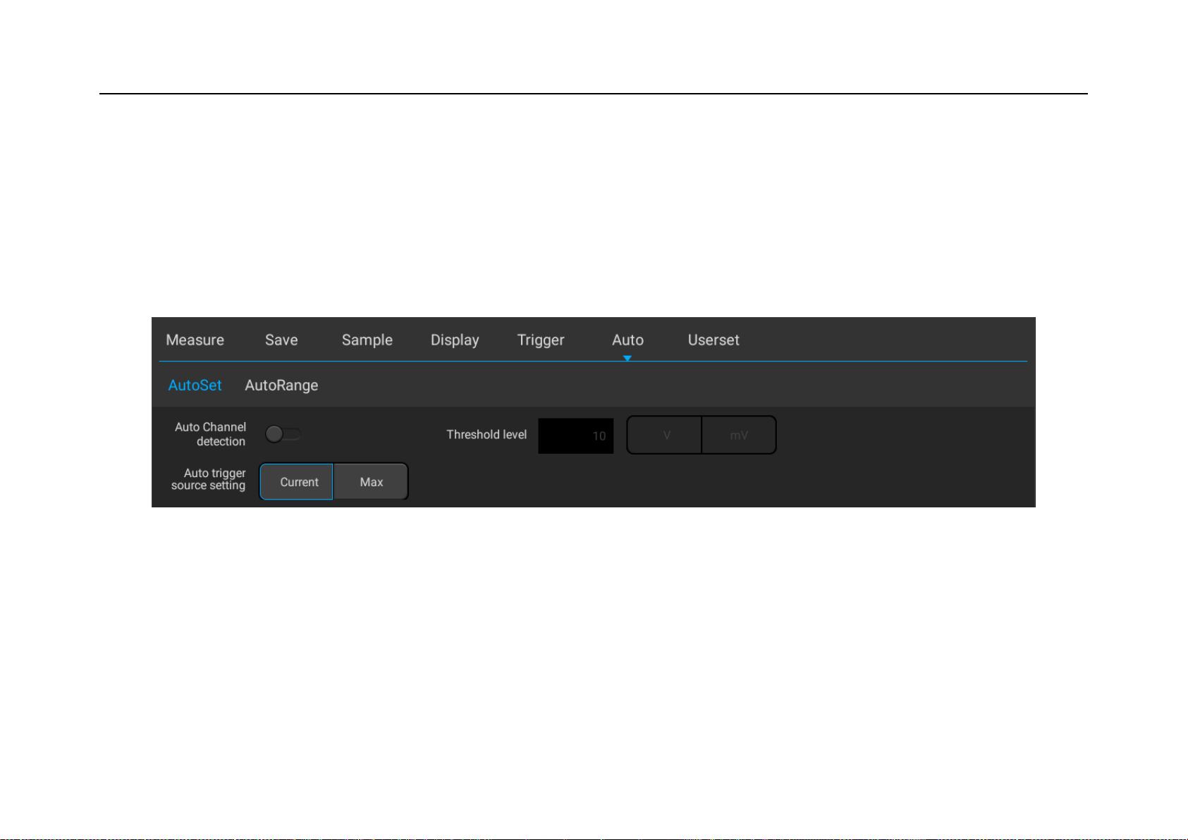
Open the main menu. Tap “Auto” to open the auto set menu, including channel open/close setting, threshold voltage
setting and trigger source setting.
Figure 2-9 Open Auto Set
Automatic configuration includes: single channel and multiple channels; automatic adjustment of the horizontal
time base, vertical sensitivity and trigger level of signal; the oscilloscope waveform is inverted off, the bandwidth
limit sets to full bandwidth, it sets as DC coupling mode, the sampling mode is normal; the trigger type is set to
edge trigger and the trigger mode is automatic.
Page 43
28
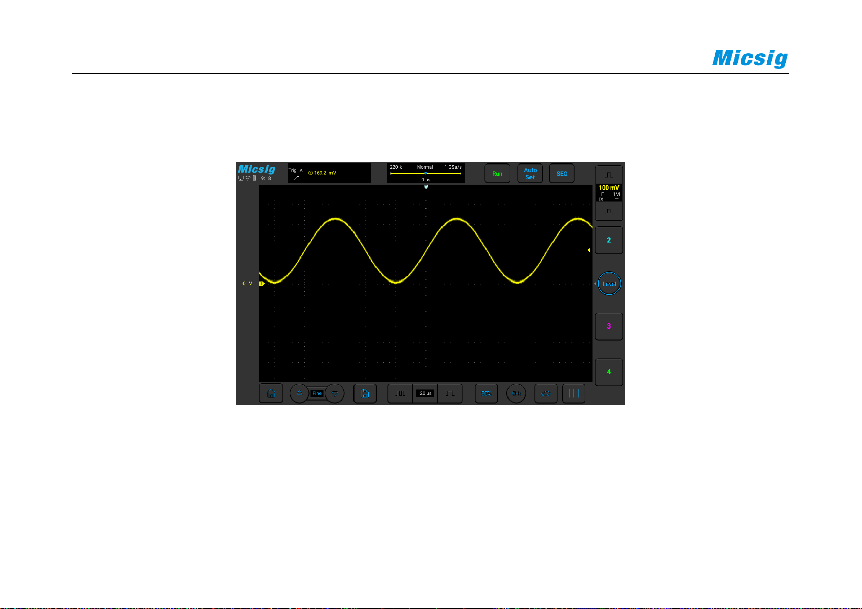
Note: The application of Auto Set requires that the frequency of measured signal is no less than 20Hz, the duty ratio
is greater than 1% and the amplitude is at least 2mVpp. If these parameter ranges are exceeded, Auto Set will fail.
Figure 2-10 Auto Set Waveform
Auto Range - Continuously automatic, the oscilloscope continuously adjusts the vertical scale, horizontal time base
and trigger level in a real-time manner according to the magnitude and frequency of signal. It is defaulted as off and
needs to be opened in the menu. This function is mutually exclusive with “Auto Set”.
Page 44

Chapter 2. Quick Start Guide of Oscilloscope
29
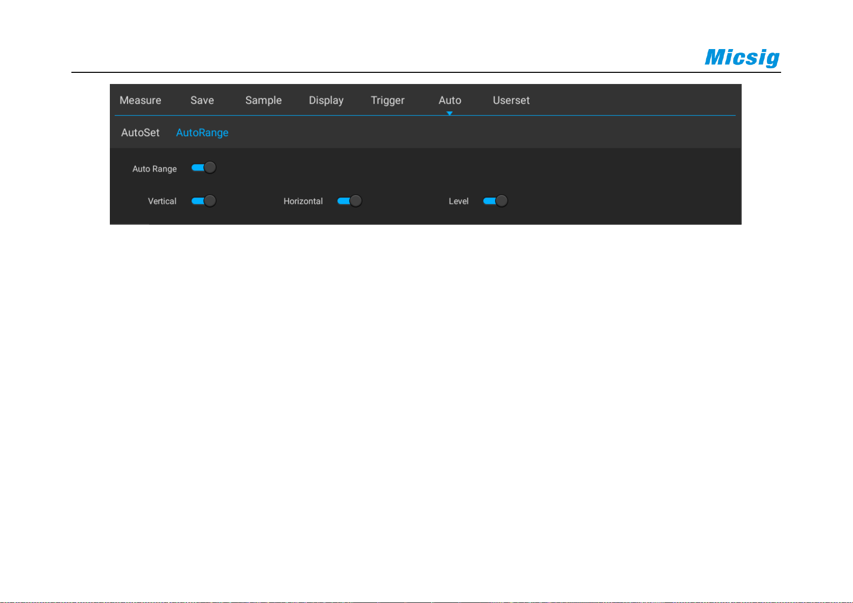
Open the main menu and tap “Auto” to open the auto range menu for the corresponding settings. When the
oscilloscope auto range function is turned on, the oscilloscope will automatically set various parameters, including:
vertical scale, horizontal time base, trigger level, etc. When the signal is connected, these parameters will
automatically change, and the signal does not need to be operated again after the change. The oscilloscope will
automatically recognize and make the appropriate changes.
Auto range: Turn the auto range function on or off
Vertical scale: Turn on the vertical scale automatic adjustment function;
Horizontal time base: Turn on the horizontal time base automatic adjustment function;
Trigger level: Turns on the auto-adjust trigger level function.
Page 45
30
Figure 2-11 Open Auto Range
Auto Range is usually more useful than Auto Set under the following situations:
1) It can analyze signals subject to dynamic changes.
2) It can quickly view several continuous signals without adjusting the oscilloscope. This function is very useful
if you need to use two probes at the same time, or if you can only use the probe with one hand because the
other hand is full.
3) Control the automatic adjustment setting of the oscilloscope.
Page 46
Chapter 2. Quick Start Guide of Oscilloscope
31
2.13 Load Factory Settings
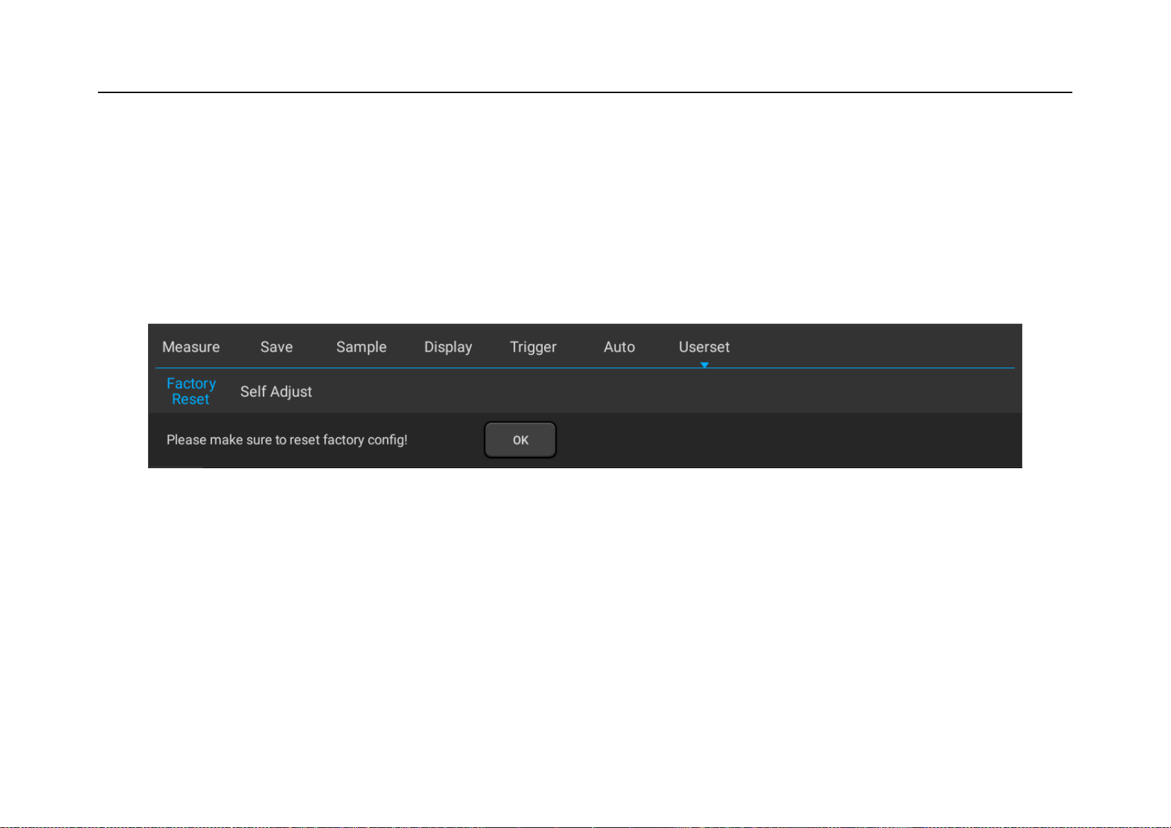
Open the main menu, tap “User Settings” to enter the user setting page. Tap “Factory Settings” and the dialog box
for loading factory settings will pop-up. Press “OK” and load the factory settings. The dialog box for loading
factory settings is shown in Figure 2-12.
Figure 2-12 Load Factory Settings
2.14 Use Auto-calibration
Open the main menu, tap “Userset” to enter the user setting page. Tap “Self Adjust” to enter the auto-calibration
mode. When the auto-calibration function is active, the upper left corner of the screen displays “Calibrating” in red,
Page 47

32
and after calibrating is finished, the word in red disappears. When the temperature changes largely, the autocalibration function can make the oscilloscope maintain the highest accuracy of measurement.
Auto-calibration should be done without probe.
Auto-calibration process takes about two minutes.
If the temperature changes above 10℃, we recommended users perform the auto-calibration.
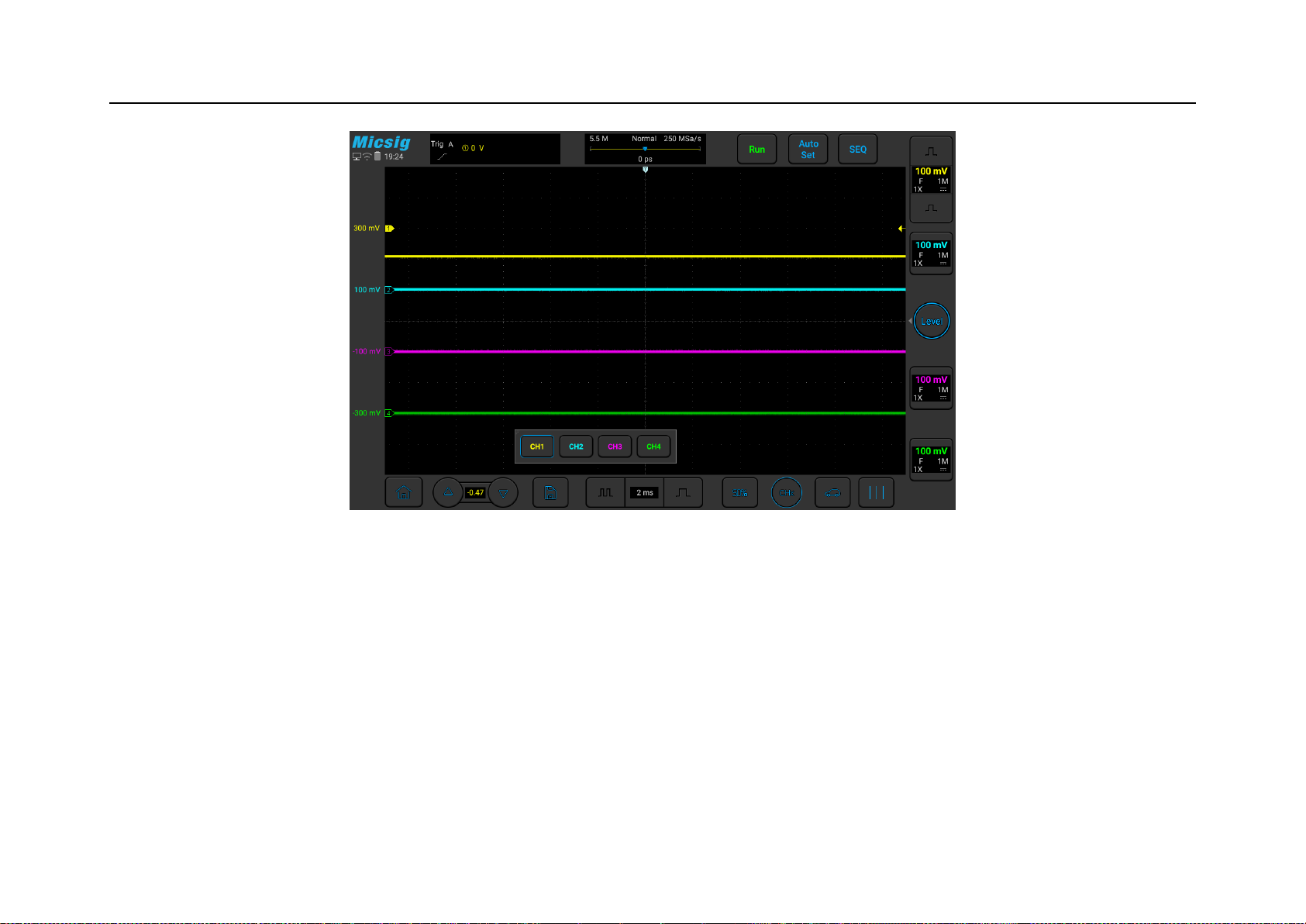
Manual zero calibration- The oscilloscope supports manual zero calibration for each channels. Click the "Fine"
button in the lower left corner would open the forced channel selection menu and display the offset value, select the
channel to be adjusted, and slide the waveform up and down to manually adjust the zero position. Tap“△”,
“▽”button can fine-tune the zero position, as shown in Figure 2-13
Page 48
Chapter 2. Quick Start Guide of Oscilloscope
33
Figure 2-13 Manual zero calibration
2.15 Passive Probe Compensation
Before connecting to any channels, users should make a probe compensation to ensure the probe match the input
channel. The probe without compensation will lead to larger measurement errors or mistakes. Probe compensation
Page 49

34
can optimize the signal path and make measurement more accurate. If the temperature changes 10℃ or above, this
program must run to ensure the measurement accuracy.
Probe compensation may be conducted in the following steps:
1) First, connect the oscilloscope probe to CH1. If a hook head is used, make sure that it is in good connection
with the probe.
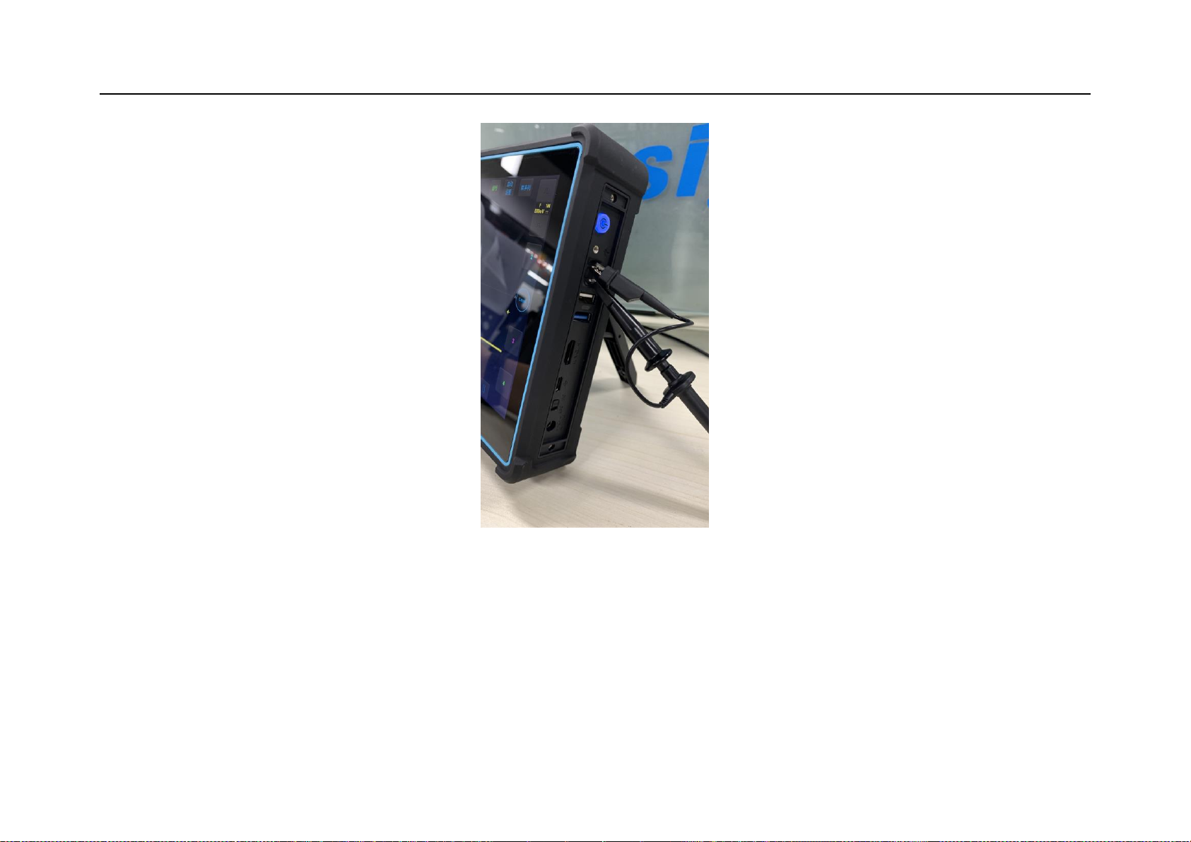
2) Connect the probe to the calibration output signal terminal and connect the probe ground to the ground
terminal. As shown in Figure 2-13.
Page 50
Chapter 2. Quick Start Guide of Oscilloscope
35
Figure 2-13 Probe Connection
3) Open the channel (if the channel is closed).
4) Adjust the oscilloscope channel attenuation coefficient to match the probe attenuation ratio.
Page 51
36
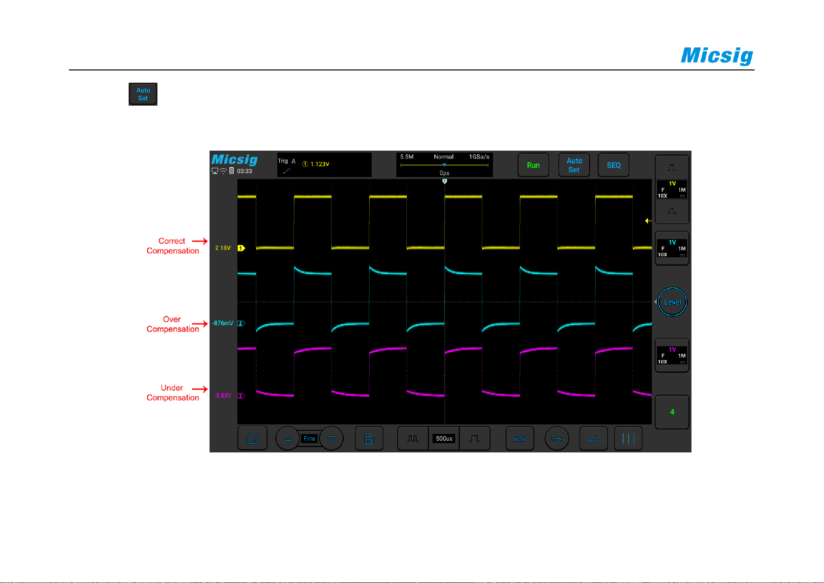
5) Tap button or manually adjust the waveform vertical sensitivity and horizontal time base. Observe the
shape of the waveform, see Figure 2-14.
Figure 2-14 Probe Compensation
Page 52
Chapter 2. Quick Start Guide of Oscilloscope
37
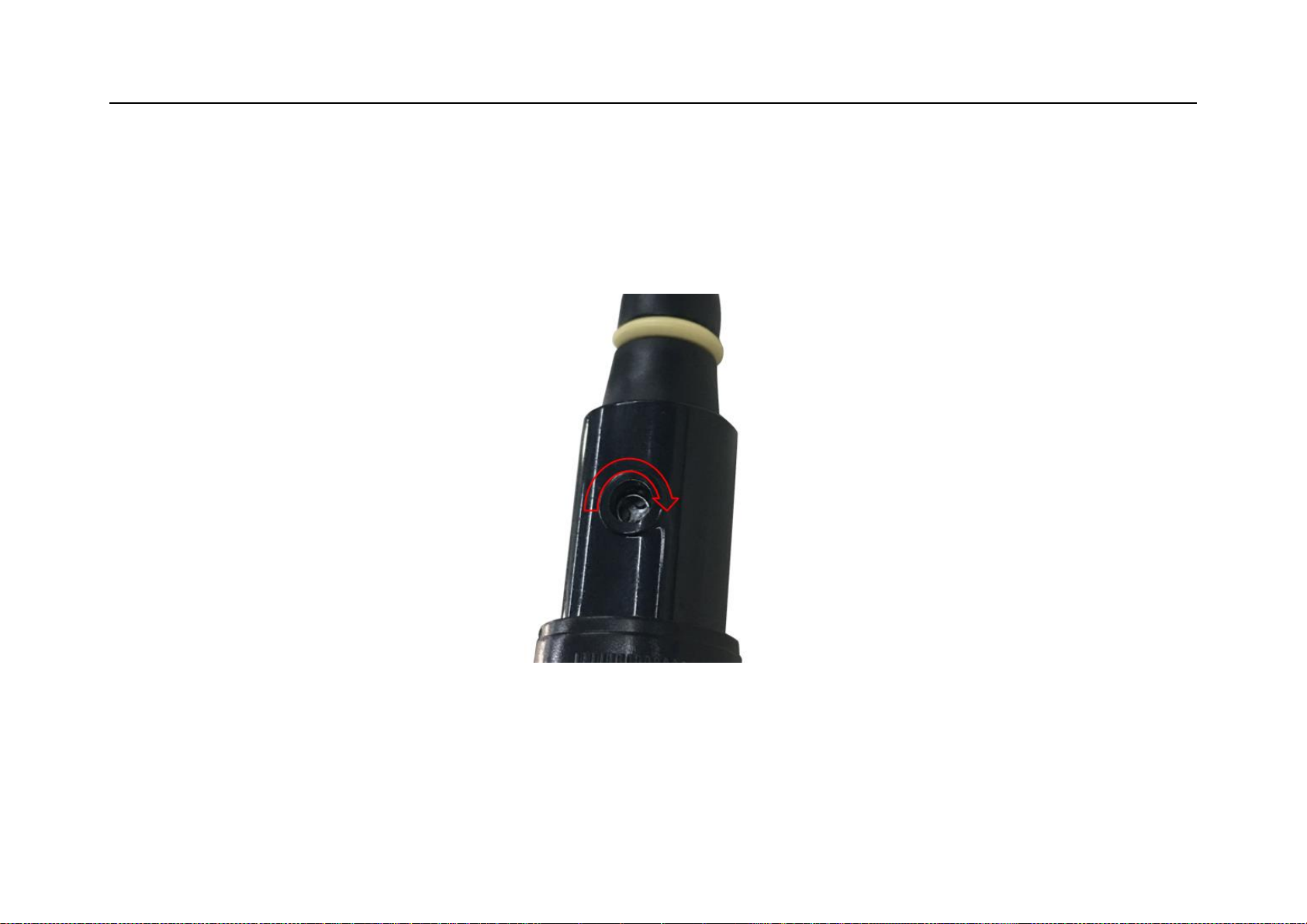
If the waveform on the screen is shown as “under-compensation” or “over-compensation”, please adjust the
trimmer capacitor until the waveform shown on the screen as “correct-compensation”. The probe adjustment is
shown in Figure 2-15.
Figure 2-15 Probe Adjustment
The safety ring on the probe provides a safe operating range. Fingers should not exceed the safety ring when using
the probe, so as to avoid electric shock.
Page 53
38
6) Connect the probe to all other oscilloscope channels (Ch2 of a 2-channel oscilloscope, or Ch 2, 3 and 4 of a 4-
channel oscilloscope).
7) Repeat this step for each channel.
Warning
Ensure the wire insulation is in good condition to avoid probe electric shock while measuring high voltage.
Keep your fingers behind the probe safety ring to prevent electric shock.
When the probe is connected a voltage source, do not touch metal parts of the probe-head to prevent electric
shock.
Before any measurement, please correctly connect the probe ground end.
2.16 Modify the Language
To modify the display language, please refer to “14.3 Settings - Language and Input Method”.
Page 54

Chapter 3 Automotive Test
39
Chapter 3 Automotive Test
This chapter contains most of the test applications of ATO automotive oscilloscopes in automotive circuits. The
purpose is to help users quickly troubleshoot and locate automotive electronics faults. It is recommended that you
read this chapter carefully to understand the general operation and use of automotive oscilloscopes.
3.1 Charging/Start Circuit
All electrical equipment of the car is powered by a power system composed of an on-board generator and a battery.
In this power system, the generator supplies power to the electrical equipment and charges the battery when the
generator is working normally. When the power generated by the generator is less than the power consumed by the
on-board electrical equipment, the battery participates in power supply to make up for its deficiency. When the
engine is working normally, it is necessary to ensure sufficient charging time for the battery to ensure that it does
not lose power. When the generator is working normally, whether to charge the battery can be indicated from the
charging indicator on the instrument panel. Due to the large speed range of the engine, the generator must be
equipped with a voltage regulator to ensure that its rated voltage is not affected by the speed and current. The power
Page 55
40
supply when the engine starts is completely provided by the battery, so the battery must ensure that there is enough
capacity to start the engine smoothly. The ATO series car-specific oscilloscope can test the charging circuit and the
starting circuit to test whether the charging/starting circuit of the car is working properly. The specific operations
are as follows::
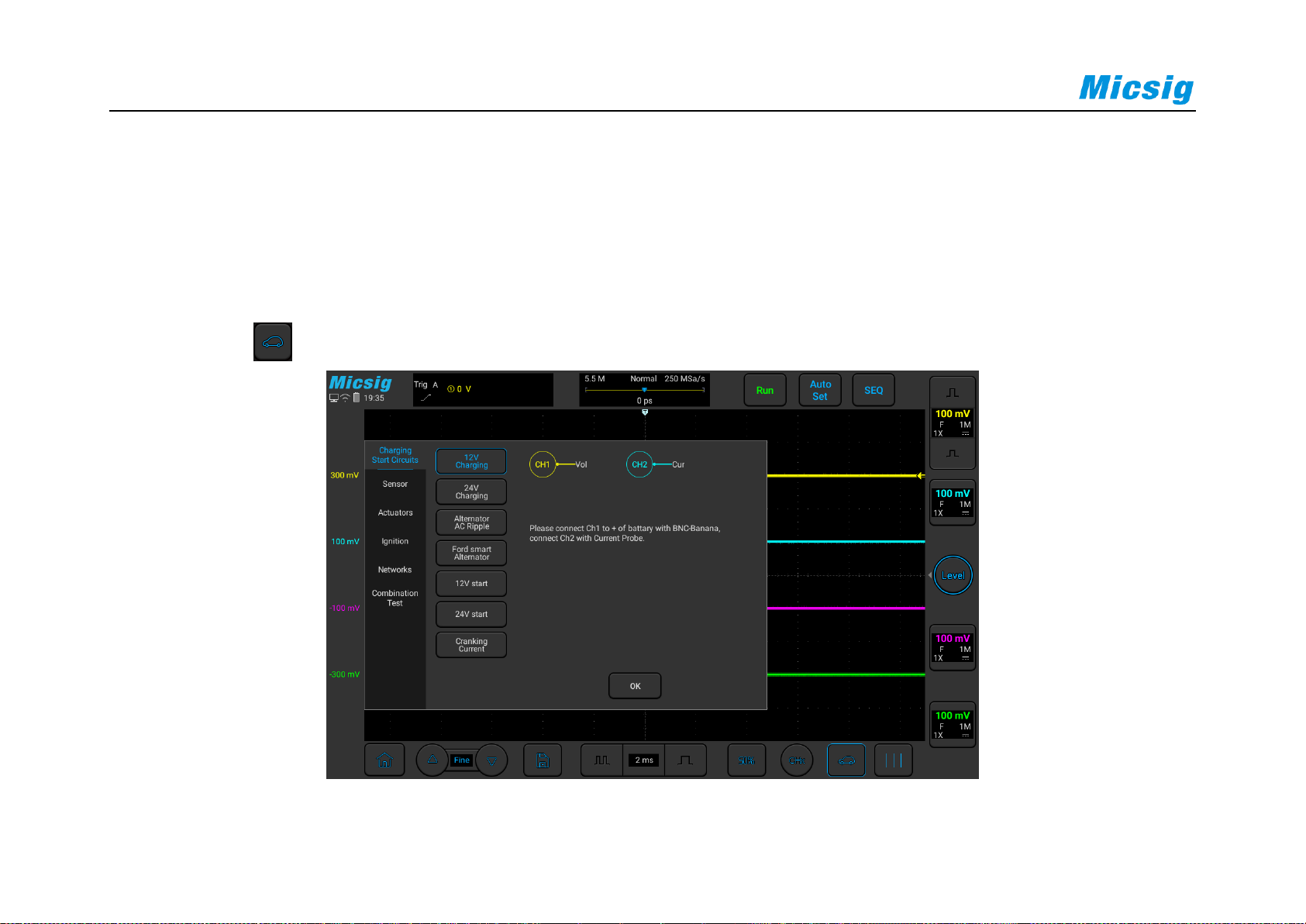
Click the icon in the lower right corner of the oscilloscope to display the screen shown in Figure 3-1:
Figure 3-1 Charging/Start Circuits
Page 56

Chapter 3 Automotive Test
41
3.1.1 12V Charging
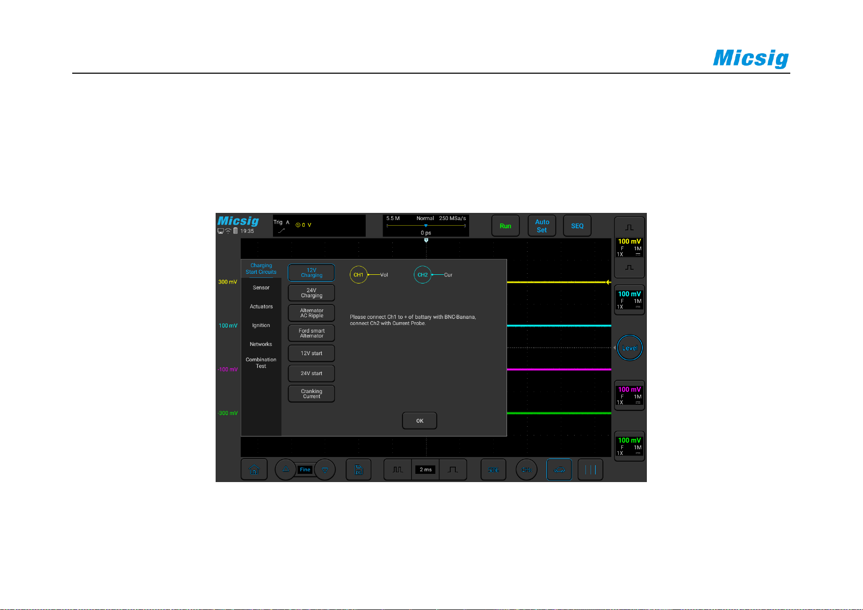
12V charging is suitable for gasoline vehicles. Use a BNC to banana cable, one end is connected to channel 1 of the
oscilloscope, and the other end is connected to the positive and negative electrodes of the battery using two large
alligator clips (the red wire is connected to the red clip to the positive electrode, and the black wire is connected to
the black clip. negative electrode). If you need to measure current, please use a current clamp of 600A and above,
connect the BNC of the current clamp to channel 2, turn on the switch of the current clamp, and clamp the current
clamp to the output power line of the generator.
The alternator provides power to the vehicle. There is little difference between different manufacturers. The
charging voltage is generally between 13.5V and 15.0V. It is not good if it is too large or too small. The output
current of the generators of different models of different manufacturers is not the same, so it needs to be estimated
according to the vehicle.
Page 57
42
Note: The generator adopts AC power generation. The voltage is converted to DC through multiple rectifier diodes.
The voltage can be measured by a multimeter. However, when the diodes are damaged, the multimeter displays the
correct readings, and the waveform can be judged by an oscilloscope.
The specific operation is shown in Figure 3-2:
Figure 3-2 12V Charging
Page 58
Chapter 3 Automotive Test
43
3.1.2 24V Charging
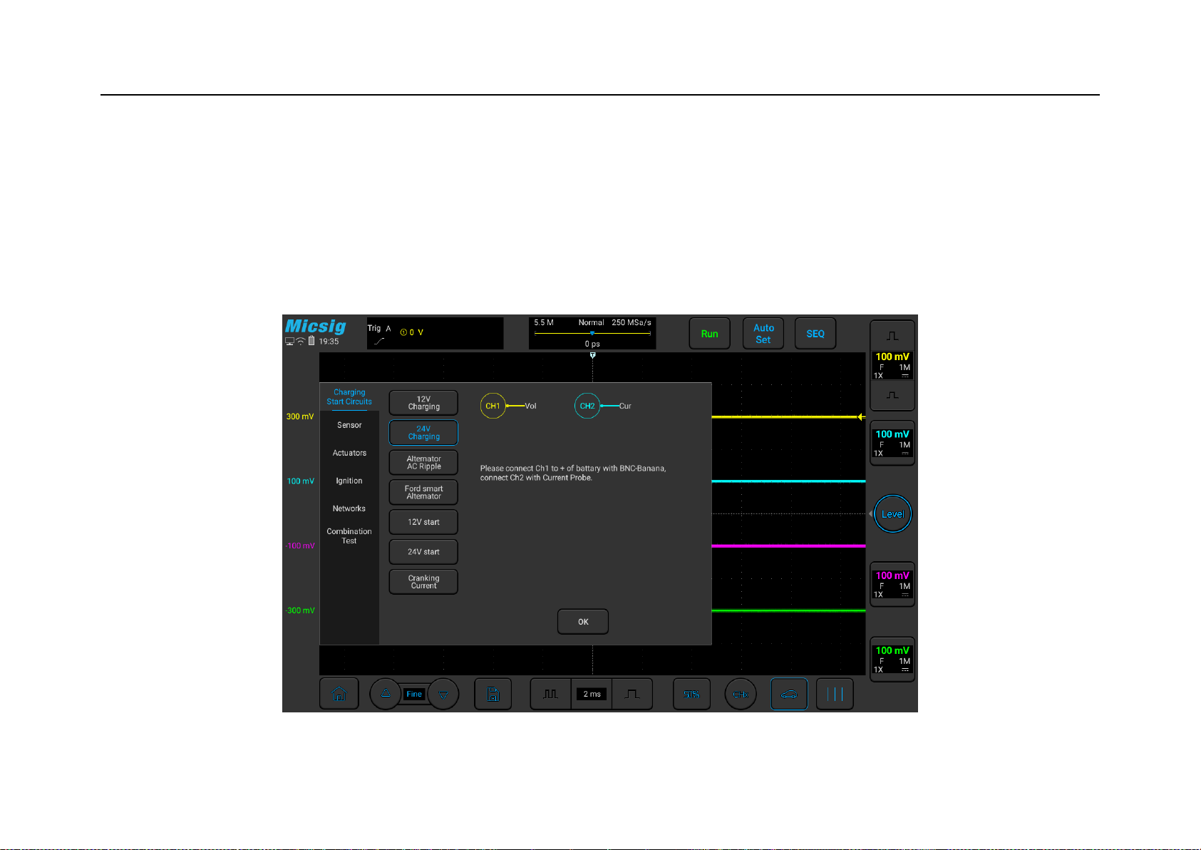
24V charging is suitable for diesel vehicles. The operation process is the same as that of 12V charging. The
reference voltage is 26.5V~30V. It can be tested with an oscilloscope. The specific operation is shown in Figure 33:
Figure 3-3 24V Charging
Page 59

44
3.1.3 Alternator AC Ripple
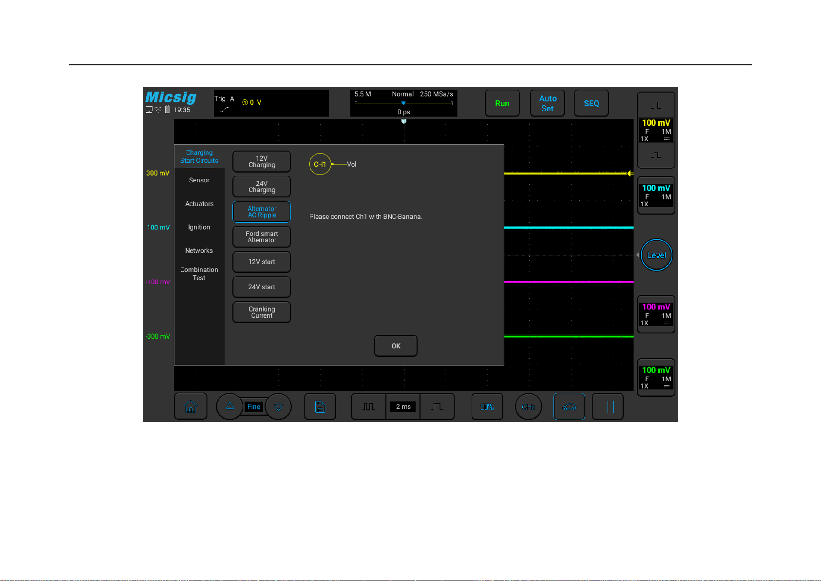
The ATO oscilloscope can test the charging ripple and assist the user to determine whether the charging process is
normal. Use a BNC to banana cable, one end is connected to the oscilloscope channel 1, and the other end is
clamped between the positive and negative electrodes of the battery (the red wire is connected to the red clip)
Connect the positive pole, and connect the black wire to the black clip to the negative pole). Start the vehicle and
start the test. At this time, the oscilloscope is coupled to AC, and what is displayed is not the true voltage value. It is
based on the DC waveform and the difference relative to the DC voltage.
As shown in Figure 3-4 below:
Page 60
Chapter 3 Automotive Test
45
Figure 3-4 Charging Ripple
Page 61

46
3.1.4 Ford Focus Smart Generator
Use a BNC to banana cable, connect one end to channel 1 of the oscilloscope, connect the black plug to the black
alligator clip to ground (battery negative), and use a needle to connect the red connector to the engine ECM to
generator output control line. Use BNC to banana cable, one end Connect to channel 2 of the oscilloscope, the other
black plug is connected to the black alligator clip to ground (the negative electrode of the battery), and the red
connector is connected to the feedback of the generator to the engine ECM with a stinger.
Use a current clamp of 600A and above, connect the BNC of the current clamp to channel 3, turn on the switch of
the current clamp, and clamp the current clamp to the output power line of the generator.
Start the vehicle and start the test. Among them, the control signal of ECM to the generator on channel 1 is square
wave/pulse width modulation signal/LIN line; the feedback signal of the generator on channel 2 is square
wave/pulse width modulation signal, which is displayed on channel 3. Is the output current of the generator.
Page 62
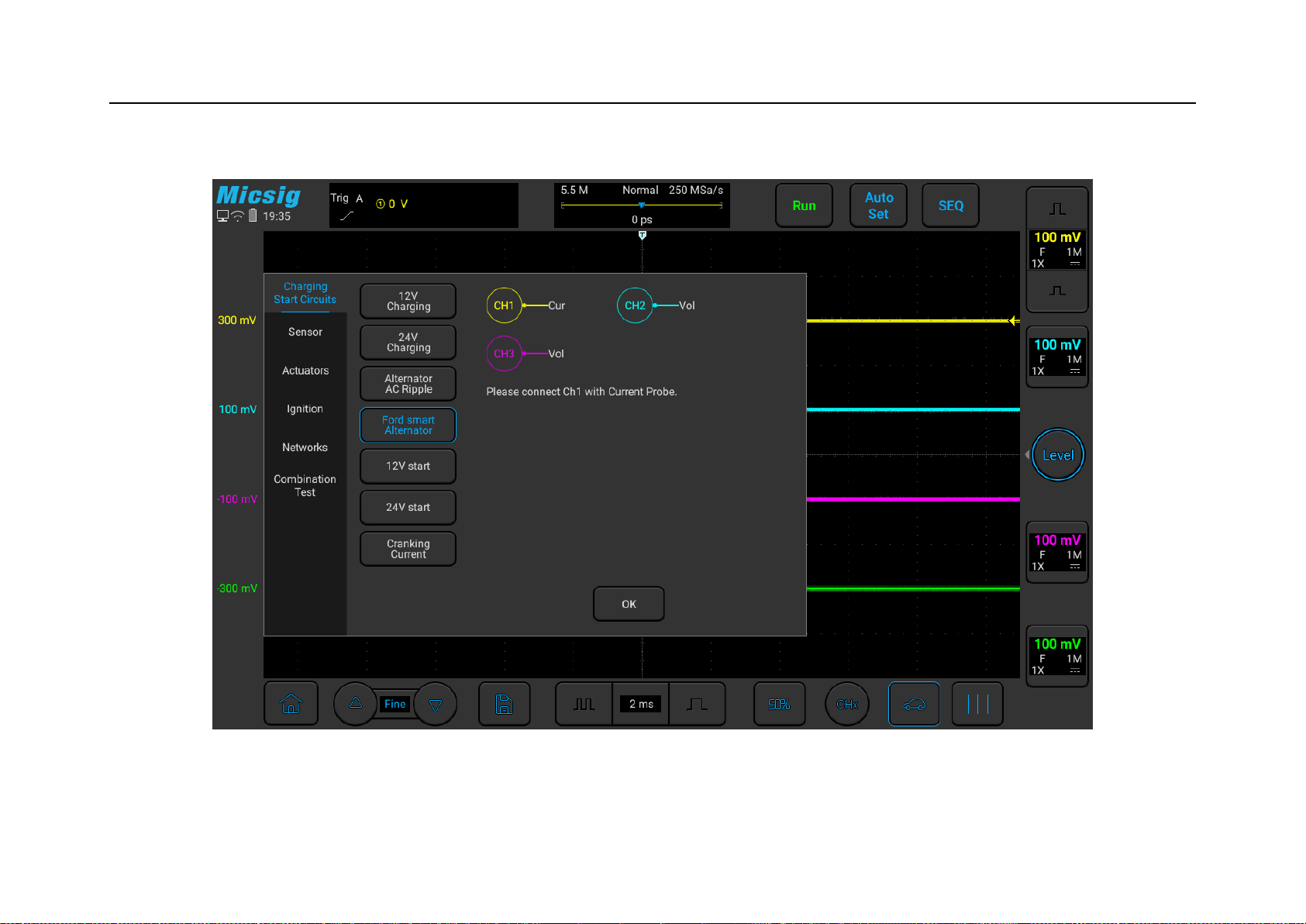
Chapter 3 Automotive Test
47
Use the ATO oscilloscope to test the Focus smart generator, the specific operation is shown in Figure 3-5:
Figure 3-5 Ford Focus Smart Generator
Page 63

48
3.1.5 12V Start
Use the ATO oscilloscope to test the start of the gasoline car, the purpose is to test whether the performance of the
battery is maintained in the normal range. Use a BNC to banana cable, connect one end to channel 1 of the
oscilloscope, and use two large alligator clips to clamp the positive and negative poles of the battery (the red wire
connects to the red clamp to the positive pole, and the black wire to the black clamp to the negative pole). Use a
current clamp above 600A, connect the BNC of the current clamp to channel 2, turn on the switch of the current
clamp, and clamp the current clamp to the positive or negative power line of the battery. You need to clamp the
entire positive or negative line. Stay, pay attention to the positive and negative polarity (positive current flows from
the positive to the negative of the battery). The specific operation is shown in Figure 3-6:
Page 64
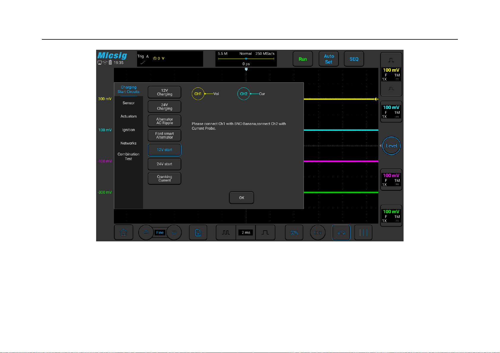
Chapter 3 Automotive Test
49
Figure 3-6 12V Start
The following figure is the actual measurement diagram of the starting voltage and current of Mazda in a certain
year:
Page 65
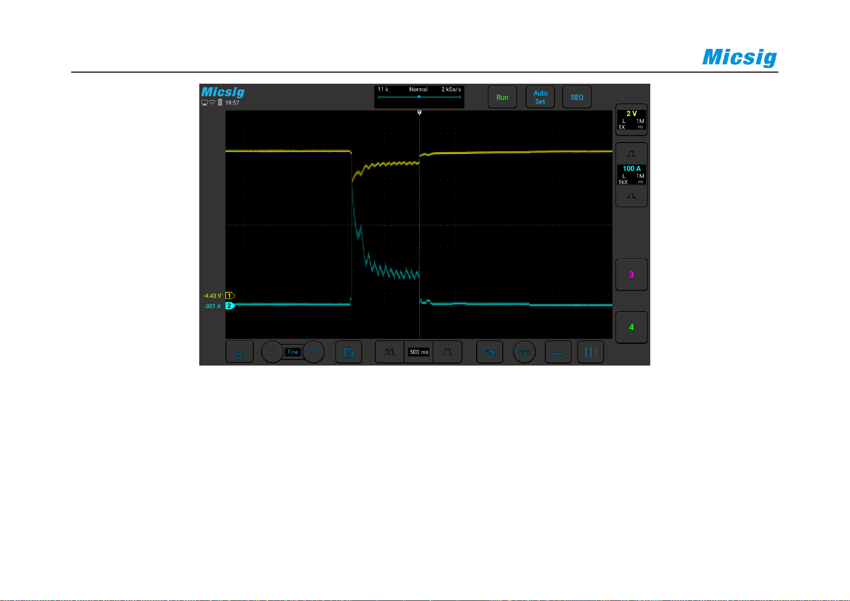
50
Figure 3-7 Starting voltage and current
3.1.6 24V Start
Use the ATO oscilloscope to test the starting process of the diesel vehicle, the purpose is to test whether the
performance of the battery is maintained in the normal range, the operation process is the same as the 12V start. The
specific operation is shown in Figure 3-8:
Page 66
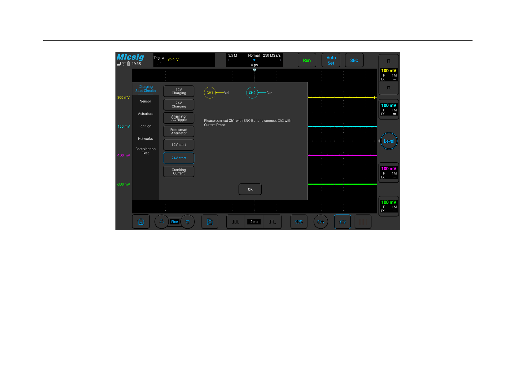
Chapter 3 Automotive Test
51
Figure 3-8 24V Start
3.1.7 Cranking Current
Use an ATO oscilloscope with a current probe to conduct a current test on the starting process of the car
(automobile or diesel car), observe whether the current waveform is normal, use a current clamp of 600A or above,
Page 67
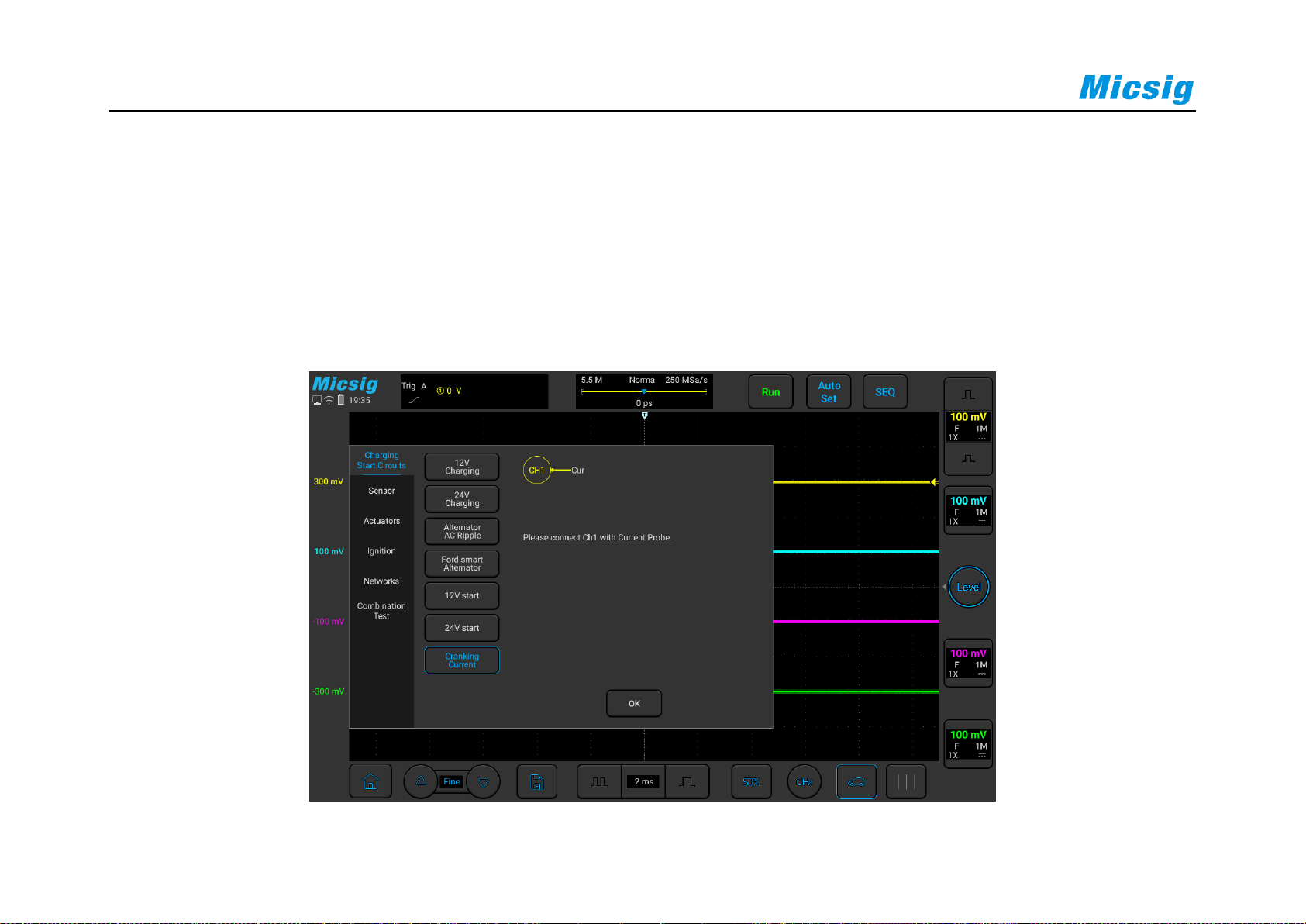
52
and connect the BNC of the current clamp to channel 2. On, turn on the switch of the current clamp and clamp the
current clamp to the positive or negative power line of the battery. You need to clamp the entire positive or negative
line. Pay attention to the positive and negative polarity (positive current flows from the positive electrode of the
battery to the negative electrode).
The specific operation is shown in Figure 3-9:
Figure 3-9 Cranking Current
Page 68

Chapter 3 Automotive Test
53
3.2 Sensor Tests
The sensor is an electronic signal conversion device that converts non-electrical information into voltage signals
and reports various information about changes in the working environment to the car computer. For example, the air
flow meter installed between the air filter and the throttle valve can measure the value of the air flow that is sucked
into the engine through the throttle valve. It converts the air flow value into a voltage signal and sends it to the
engine ECU (control computer), the control computer adjusts the corresponding fuel injection volume according to
the change of air flow to achieve the goal of the best combustion ratio. Another example is a vehicle speed sensor.
Its function is to convert the vehicle speed into a voltage signal and send it to the trip computer. The trip computer
controls the shift timing to achieve upshift or downshift.
With the continuous development of cars in the direction of intelligence and new energy, the number of sensors on
the car body has shown a trend of sharp increase, and there are nearly 100 sensors on the mid-to-high-end cars of
the company. The ATO series special oscilloscope can directly measure the signal waveform of the sensor. By
comparing with the standard waveform during normal operation, it is easy to find whether the sensor is normal. The
Page 69

54
ATO series oscilloscope can test the following types of sensors. The purpose is to compare the real-time waveforms
with the standard waveforms to help users find problems. The following are expanded and explained separately:
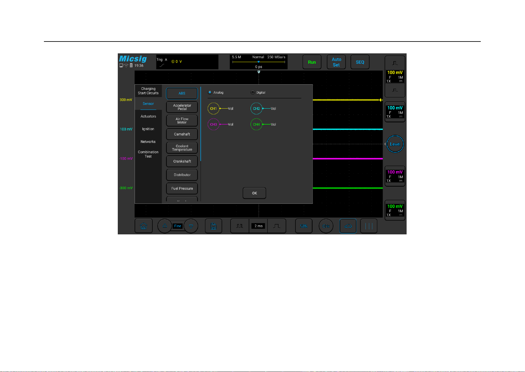
3.2.1 ABS
The ABS wheel speed sensor is divided into analog and digital. The analog sensor has 2 signal terminals, the signal
is a sine wave, and the frequency of the sine wave represents the speed. Digital sensors generally have 3 terminals,
power, signal, and ground; the signal line needs to be tested, the signal is a square wave pulse, and the square wave
frequency represents the speed.
When testing, use BNC to banana cable, the BNC head is connected to the oscilloscope, and the banana head is
connected to the sensor or the ECM pin to test 1/2/4 signals at the same time. Shown as Figure 3-10:
Page 70
Chapter 3 Automotive Test
55
Figure 3-10 ABS Wheel Speed Sensor
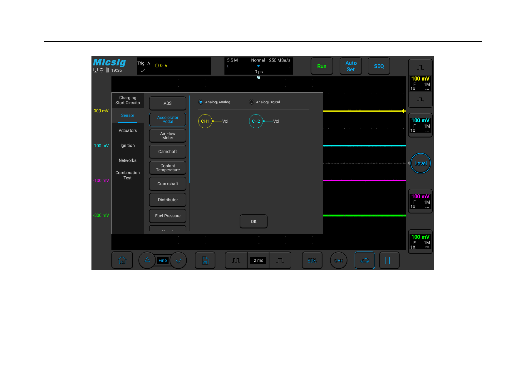
3.2.2 Accelerator pedal
The accelerator pedal is the signal of the automobile accelerator. There are generally 2 groups, each pair of 3 wires,
power, signal, and ground. Divided into analog/analog and analog/digital. Analog/analog signal is two analog
Page 71

56
signals, usually there are two ways, one is deviation signal: one signal is from 0.3V→4.8V, which rises as the
accelerator pedal is depressed, and the other is 4.8V→0.3V, with Depress the accelerator pedal and descend. The
other is the same direction signal, but the voltage is different, one is 0.5V→2.5V, the other is 1V→4.5V; (the
voltage range is for reference only, the voltage range may be slightly different for different models, but the trend is
the same).
Use ATO oscilloscope to test the accelerator pedal sensor, the specific operation is shown in Figure 3-11:
Page 72
Chapter 3 Automotive Test
57
Figure 3-11 Accelerator Pedal
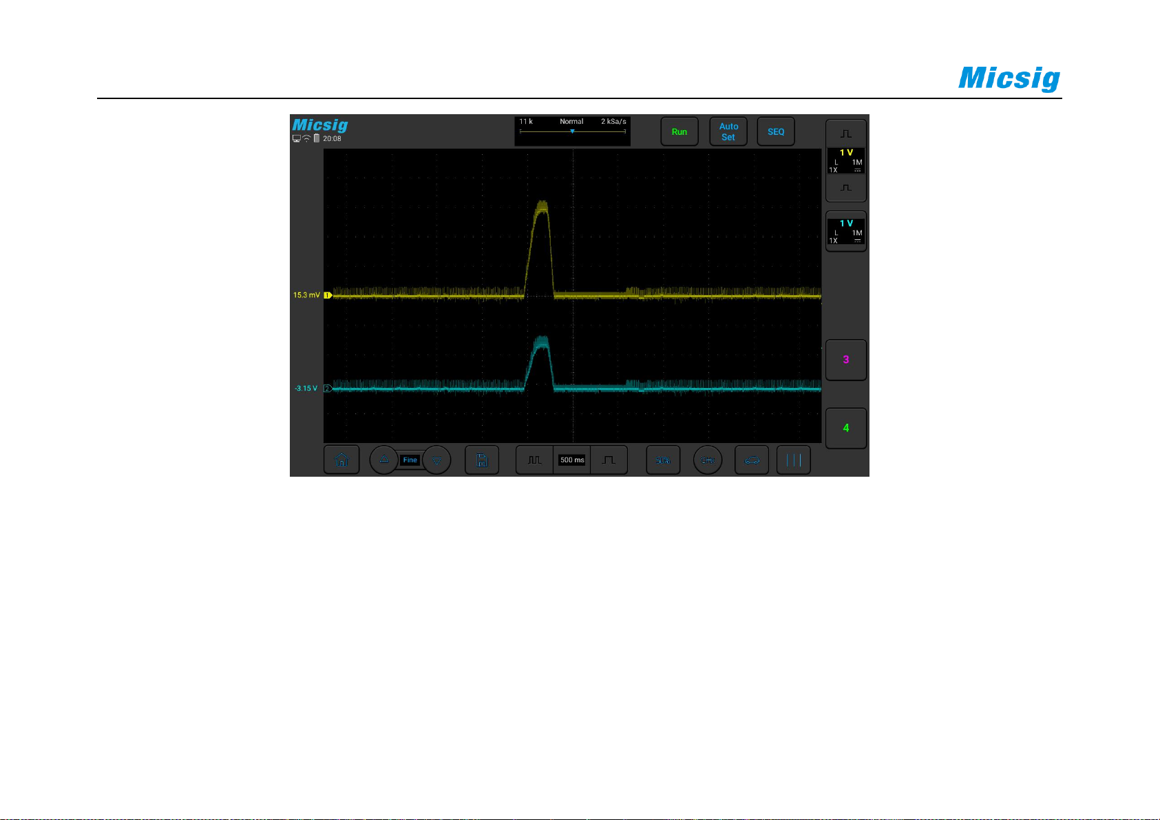
The following picture is the actual measurement diagram of the accelerator pedal sensor of a certain model:
Page 73
58
3.2.3 Air Flow Meter
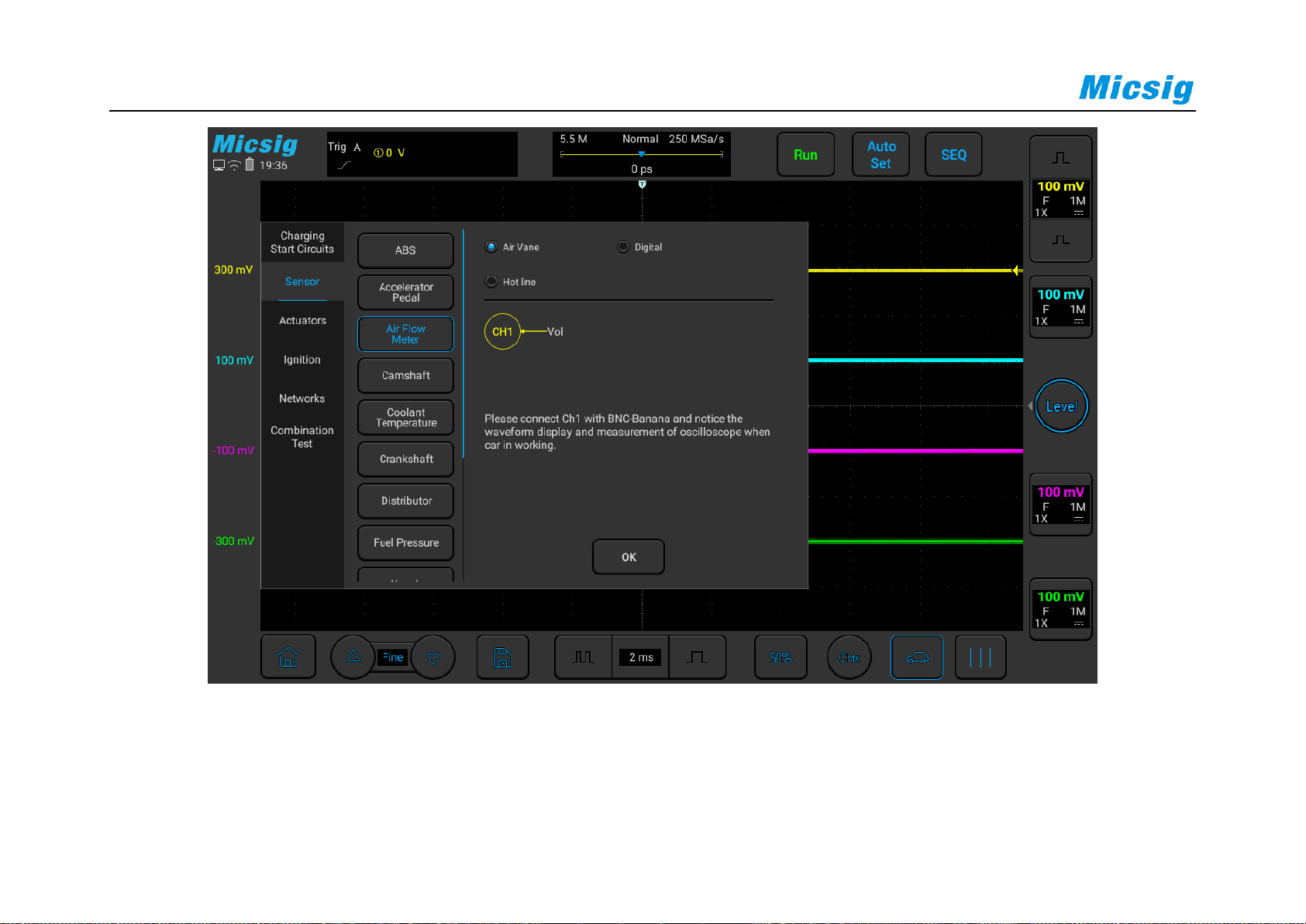
Air flow meters generally have vane type, hot wire type, digital type, etc.; among them: vane type and hot wire type
are both analog output, and the output voltage is proportional to the air flow, generally 0.5V~4.5V, but the non-
linear ratio, It needs to be corrected in the ECM; the general output voltage is about 1V at idling speed, and the
Page 74

Chapter 3 Automotive Test
59
voltage rises rapidly during acceleration, reaching a voltage of 4V~4.5V. After stopping the acceleration, it will
return to the idling voltage; the output shows 0V or 5V is not normal.
The digital type has a digital circuit inside the sensor. The output signal is a square wave. The frequency is used to
represent the air flow. A higher frequency means a higher air intake. Use a BNC to banana cable and connect one
end to channel 1 of the oscilloscope. The black plug on the other end is grounded, and the red connector is
connected to the signal wire of the air flow sensor with a needle. Start the vehicle, quickly depress the accelerator
pedal and release it to test, you can view the waveform.
Use the ATO oscilloscope to test the throttle air flowmeter sensor (the air flowmeter is divided into three types:
analog, digital, and hot wire, please test according to different types), the specific operation is shown in Figure 312:
Page 75
60
Figure 3-12 Air flow meter
Page 76

Chapter 3 Automotive Test
61
3.2.4 Camshaft
The camshaft sensor is generally used for timing, and is often tested in conjunction with the crankshaft sensor to
determine the timing of the vehicle. There are one or two camshaft sensors in the common car models, and the use
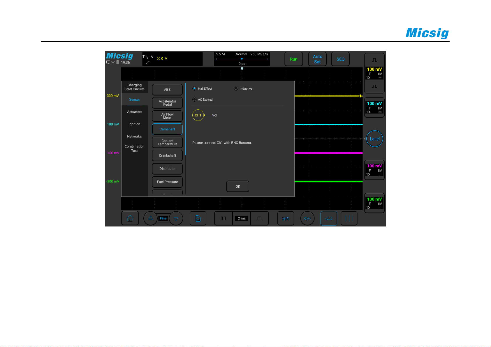
of four is relatively small. Common camshaft sensors are Hall type/induction type/AC excitation type;
Hall sensor output is square wave, high voltage can be 5V or 12V; generally 3-wire, power, signal, ground;
inductive sensor output is a sine wave signal or square wave signal, generally 2-wire; AC excitation The output of
the type sensor is multiple sine waves (there is a missing piece at the end of the camshaft, so that the signal
changes, and the position of the No. 1 cylinder is judged at the missing place), generally 2-wire.
Use a BNC to banana cable, connect one end to channel 1 of the oscilloscope, the other end of the black plug is
grounded, and the red connector uses a needle to connect the signal line of the camshaft sensor.
Shown in Figure 3-13:
Page 77
62
Figure 3-13 Camshaft
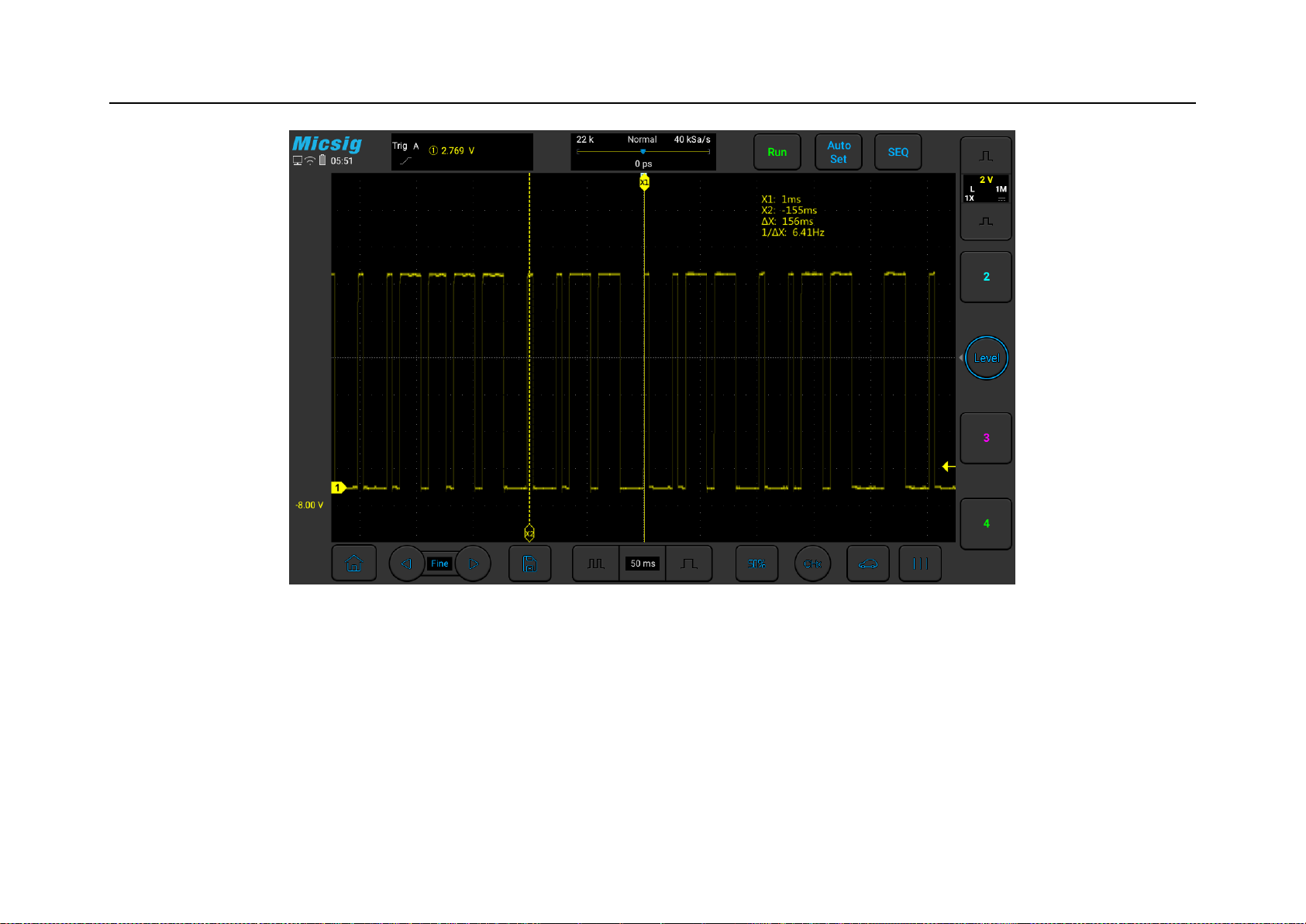
The following figure is the actual measurement diagram of the camshaft position sensor (Hall type) of a certain
model:
Page 78
Chapter 3 Automotive Test
63
Figure 3-14 Camshaft position sensor (Hall type)
3.2.5 Coolant Temperature
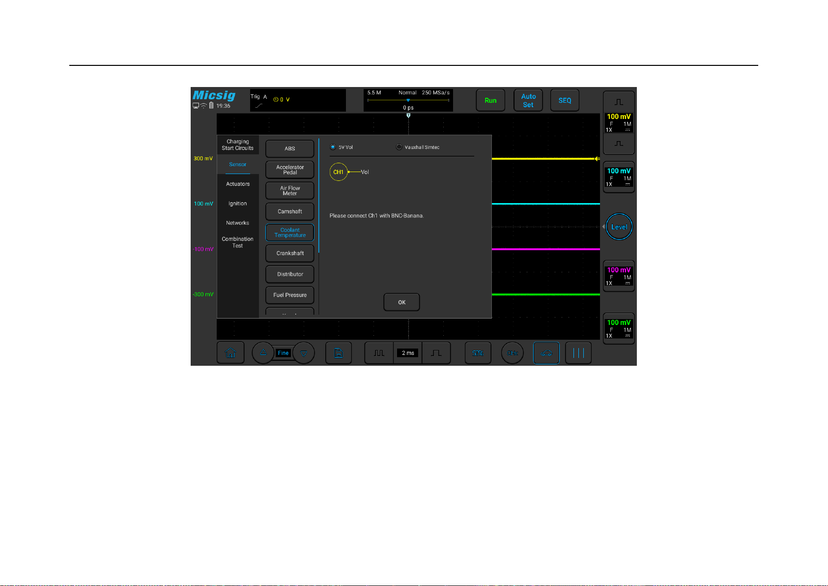
The coolant temperature sensor is usually called a water temperature sensor. Generally, it contains a thermistor. As
the temperature increases, the resistance becomes smaller, which causes the output voltage to change, and the water
Page 79

64
temperature changes slowly, so the voltage also changes slowly. Different models have different performances, and
the output voltage can increase with the water temperature, it can also decrease with the water temperature.
However, there is a special sensor called the Vauxhaus sensor. The output voltage of this sensor is 3-4V when the
vehicle is cold. As the vehicle starts, the temperature rises and the voltage gradually decreases. It is generally 1V
during normal operation, but as the vehicle temperature rises, when the vehicle temperature reaches 40-50 degrees,
the ECM will switch the voltage to make the sensor voltage rise rapidly to 3-4V, so as to achieve more accurate
voltage output at high temperatures.
Use a BNC to banana cable, one end is connected to channel 1 of the oscilloscope, the other end is grounded with
the black plug, and the red connector is connected to the signal wire of the coolant sensor (the ground wire of the
coolant) with a needle probe.
Use ATO oscilloscope to test the coolant temperature sensor, the specific operation is shown in Figure 3-15:
Page 80
Chapter 3 Automotive Test
65
Figure 3-15 Coolant Temperature
3.2.6 Crankshaft
The crankshaft sensor is installed in many places, which can be near the front pulley or on the rear flywheel. The
ECM judges the precise position of the engine based on its output signal. Usually there are induction type and Hall
Page 81

66
type: the induction type output is usually a sine wave, there are missing teeth on the disk, and the sine wave will be
missing in the missing teeth; this kind of sensor is generally 2-wire; the Hall type output is usually a square wave .
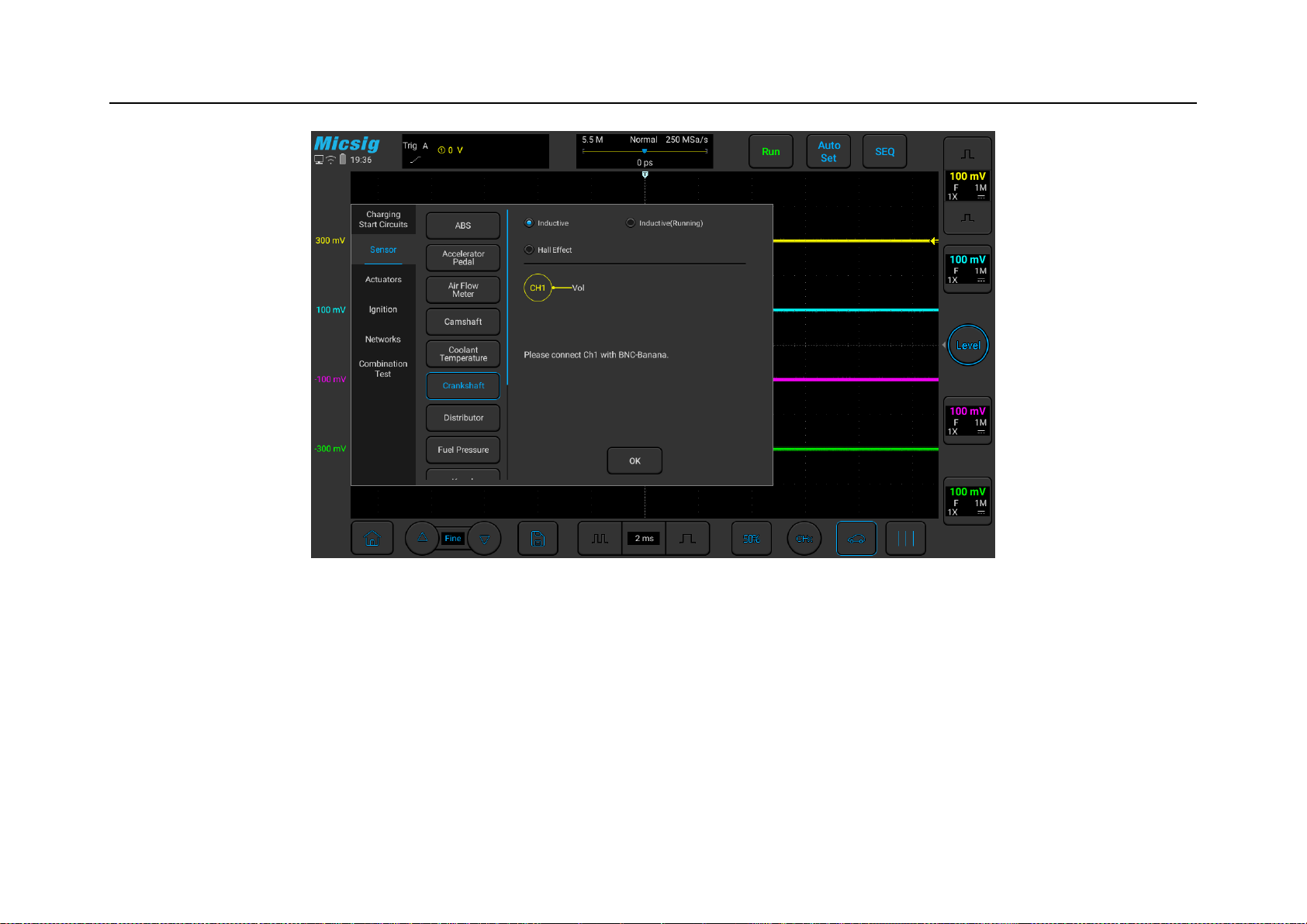
Generally 3-wire, power, signal, and ground. Use a BNC to banana cable, one end is connected to channel 1 of the
oscilloscope, the other end is grounded with the black plug, and the red connector is connected to the signal line of
the camshaft sensor with a needle.
Use the ATO oscilloscope to test the crankshaft position sensor, the specific operation is shown in Figure 3-16:
Page 82
Chapter 3 Automotive Test
67
Figure 3-16 Crankshaft position sensor
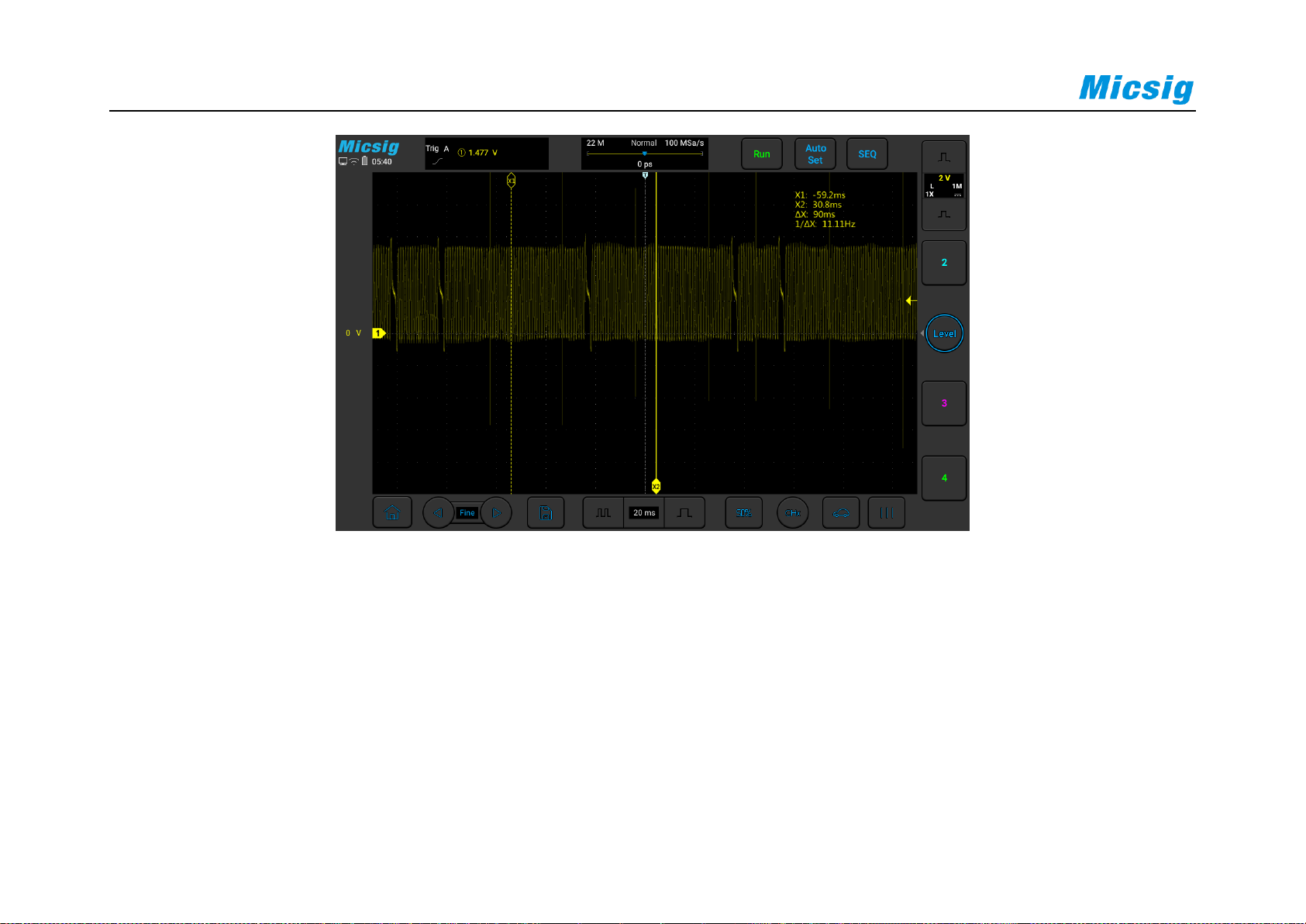
The figure below is the actual measurement of the crankshaft position sensor (inductive) of a certain model:
Page 83
68
3.2.7 Distributor
Distributor appears on models with high-voltage cables, and distribute the generated high voltages to spark plugs in
sequence. Distributors generally have Hall type and induction type. Hall type is generally 3-wire, voltage, signal,
and ground. The output is square wave. Inductive type is generally 2-wire. The output is sensing signal; use BNC to
Page 84
Chapter 3 Automotive Test
69
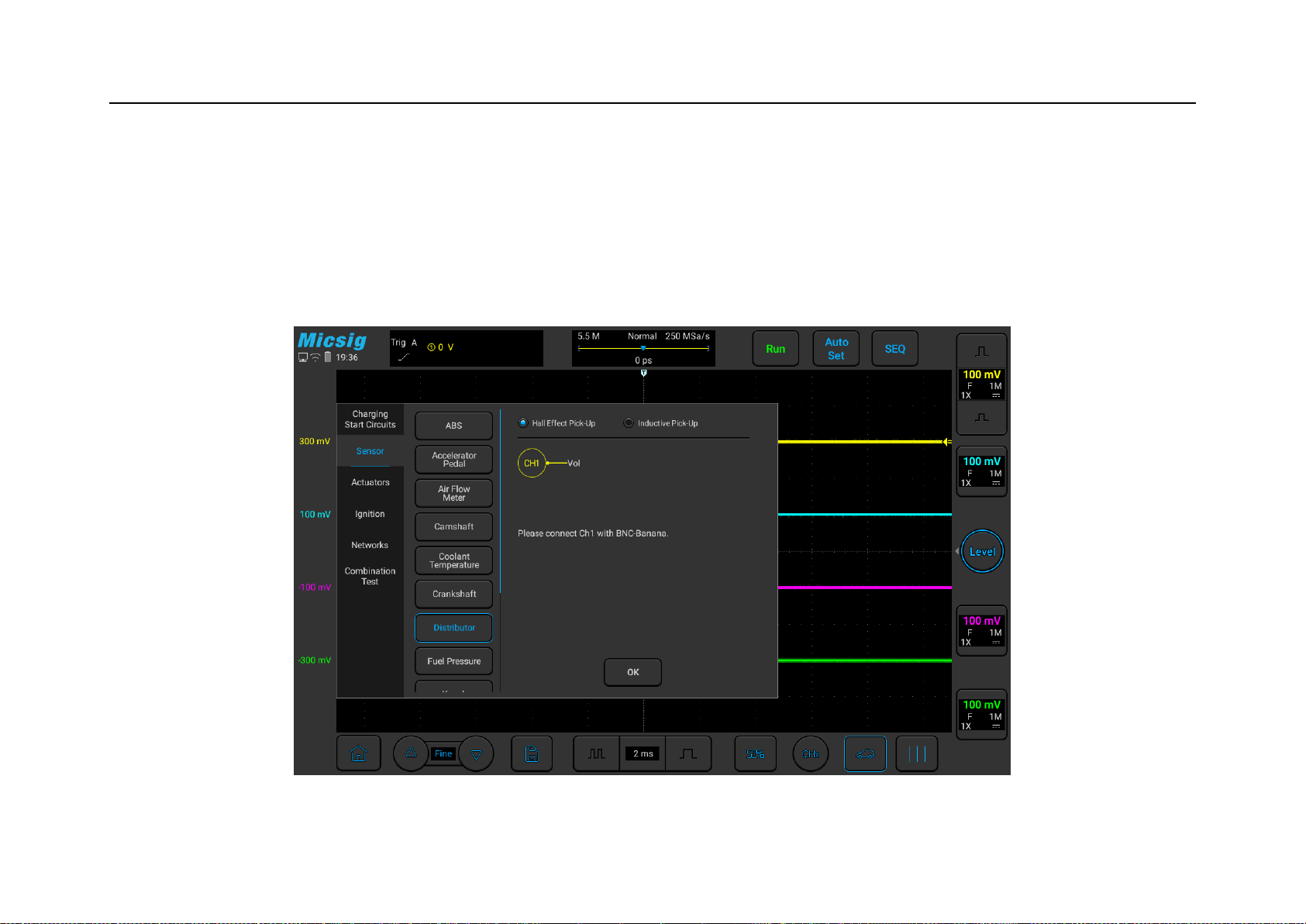
banana cable, one end is connected to channel 1 of the oscilloscope, and the other end is black The plug is
grounded, and the red connector is connected to the signal line of the distributor with a needle.
Use the ATO oscilloscope to test the distributor sensor (divided into two types: Hall effect and induction). The
specific operation is shown in Figure 3-17:
Figure 3-17 Distributor
Page 85

70
3.2.8 Fuel pressure
Fuel pressure signals generally appear on high-pressure fuel rails or sensors or common rail diesel vehicles, and the
pressure is relatively high. Generally, the fuel pressure is proportional to the output voltage, and the voltage
increases with the angle of the accelerator pedal (no-load and full-load will affect the voltage rise time).
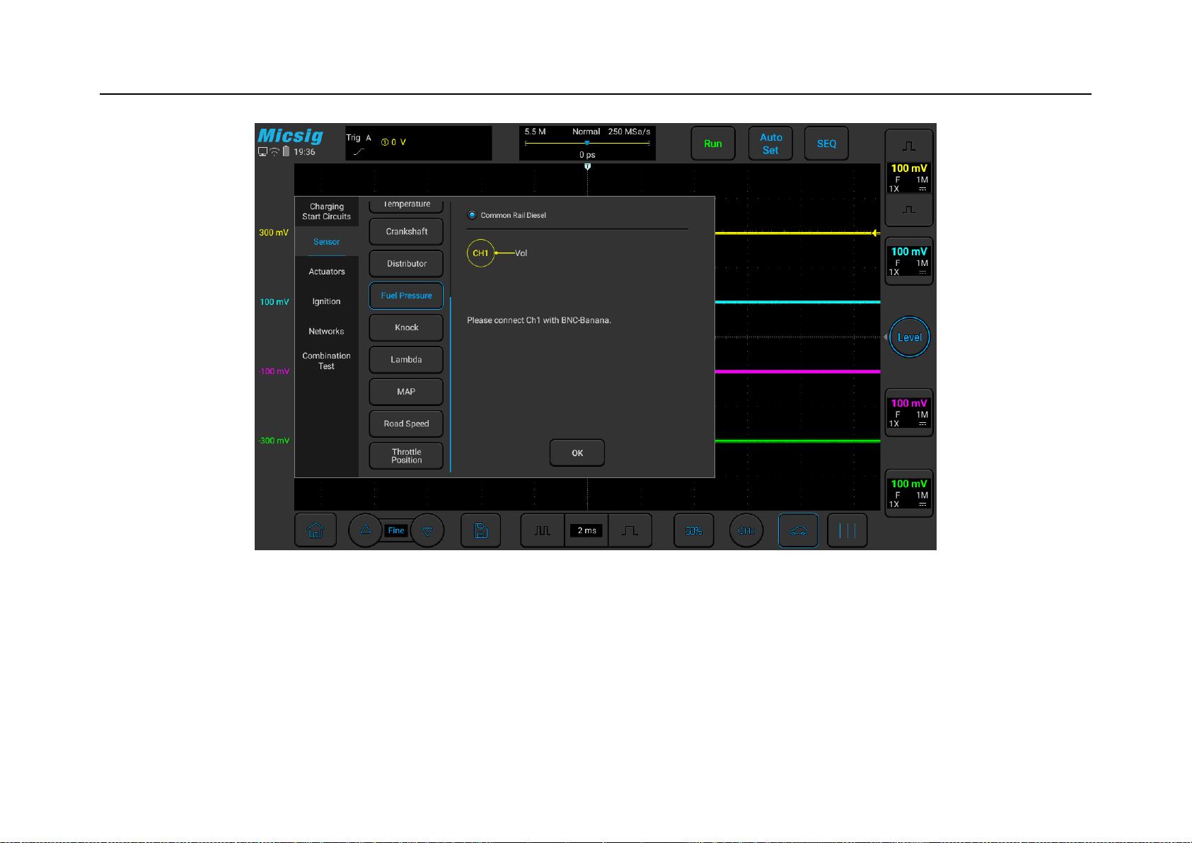
Use a BNC to banana cable, connect one end to channel 1 of the oscilloscope, the other end of the black plug is
grounded, and the red connector uses a needle to connect the signal line of fuel pressure.
Use ATO oscilloscope to test the fuel pressure sensor, the specific operation is shown in Figure 3-18:
Page 86
Chapter 3 Automotive Test
71
Figure 3-18 Fuel Pressure Sensor Test
Page 87

72
3.2.9 Knock
The knock sensor is a passive device, generally 2-wire, signal and ground, no external power supply is required,
and a signal will be generated when it is subjected to vibration. It can also be removed for testing. The signal can be
generated by tapping, and the signal amplitude generally does not exceed 5V; if the sensor is removed and then
reinstalled, please be careful not to cause excessive torque to avoid damage to the sensor.
There may be several reasons for knocking: the ignition angle is too advanced, too much carbon deposits in the
combustion chamber, the engine temperature is too high, the air-fuel ratio is too lean, the fuel is not clean enough,
and the fuel octane number is too low.
Use a BNC to banana cable, connect one end to channel 1 of the oscilloscope, the other end of the black plug is
grounded, and the red connector is connected to the signal line of the knock sensor with a needle.
Use ATO oscilloscope to test the knock sensor, the specific operation is shown in Figure 3-19:
Page 88
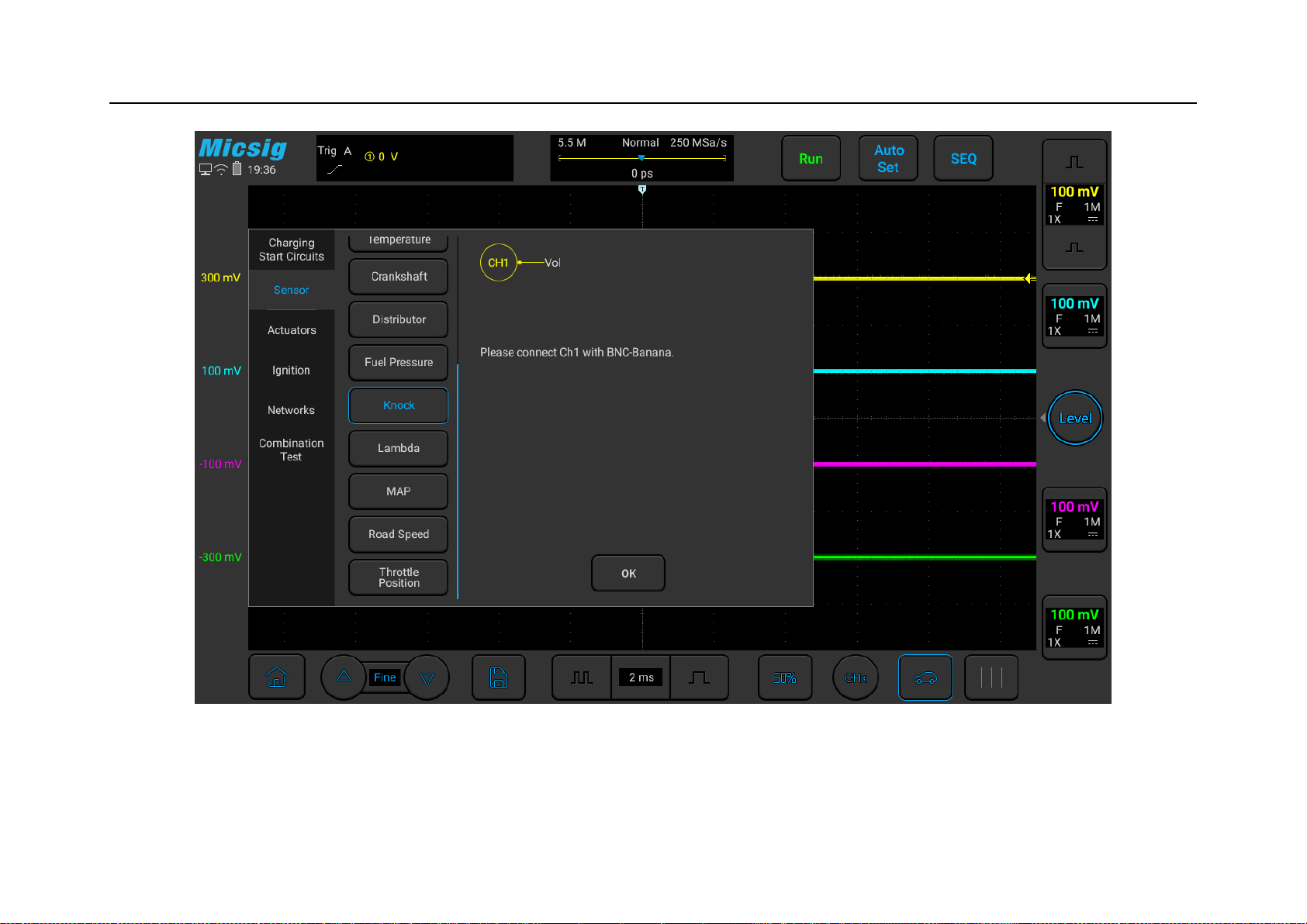
Chapter 3 Automotive Test
73
Figure 3-19 Knock Sensor test
Page 89
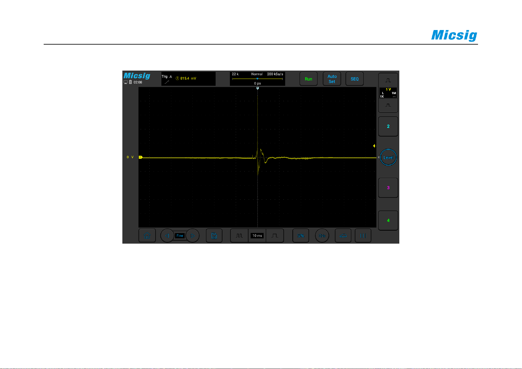
74
The following picture is the actual measurement diagram of the knock sensor of a certain model:
3.2.10 Lambda
The Lambda, or Oxygen Sensor is generally installed on the exhaust pipe, before the catalytic converter. It is a
feedback sensor used to sense the oxygen content in the exhaust gas, so that the ECM can judge the combustion
situation in the combustion chamber and adjust the fuel supply of the engine.
Page 90

Chapter 3 Automotive Test
75
There are several types of oxygen sensors: titanium oxygen, zirconium oxygen, and front & rear dual oxygen
sensors; the signal switching frequency is about 1 Hz, and it can only work when the temperature is normal. The
voltage is high when the mixture is thick, and the voltage is low when the mixture is thin.
Use a BNC to banana cable, one end is connected to channel 1 of the oscilloscope, the other end is grounded with
the black plug, and the red connector is connected to the signal line (pre-oxygen) of the oxygen sensor with a
needle. Use a BNC to banana cable, connect one end to channel 2 of the oscilloscope, ground the black plug on the
other end, and use a needle to connect the red connector to the signal line of the oxygen sensor (rear oxygen, if
there is no rear oxygen sensor, no test is required). If you want to measure current, connect the BNC end of the
current clamp to channel 3 of the oscilloscope, and clamp the clamp on the heating wire.
Use ATO oscilloscope to test the oxygen sensor, the specific operation is shown in Figure 3-20:
Page 91
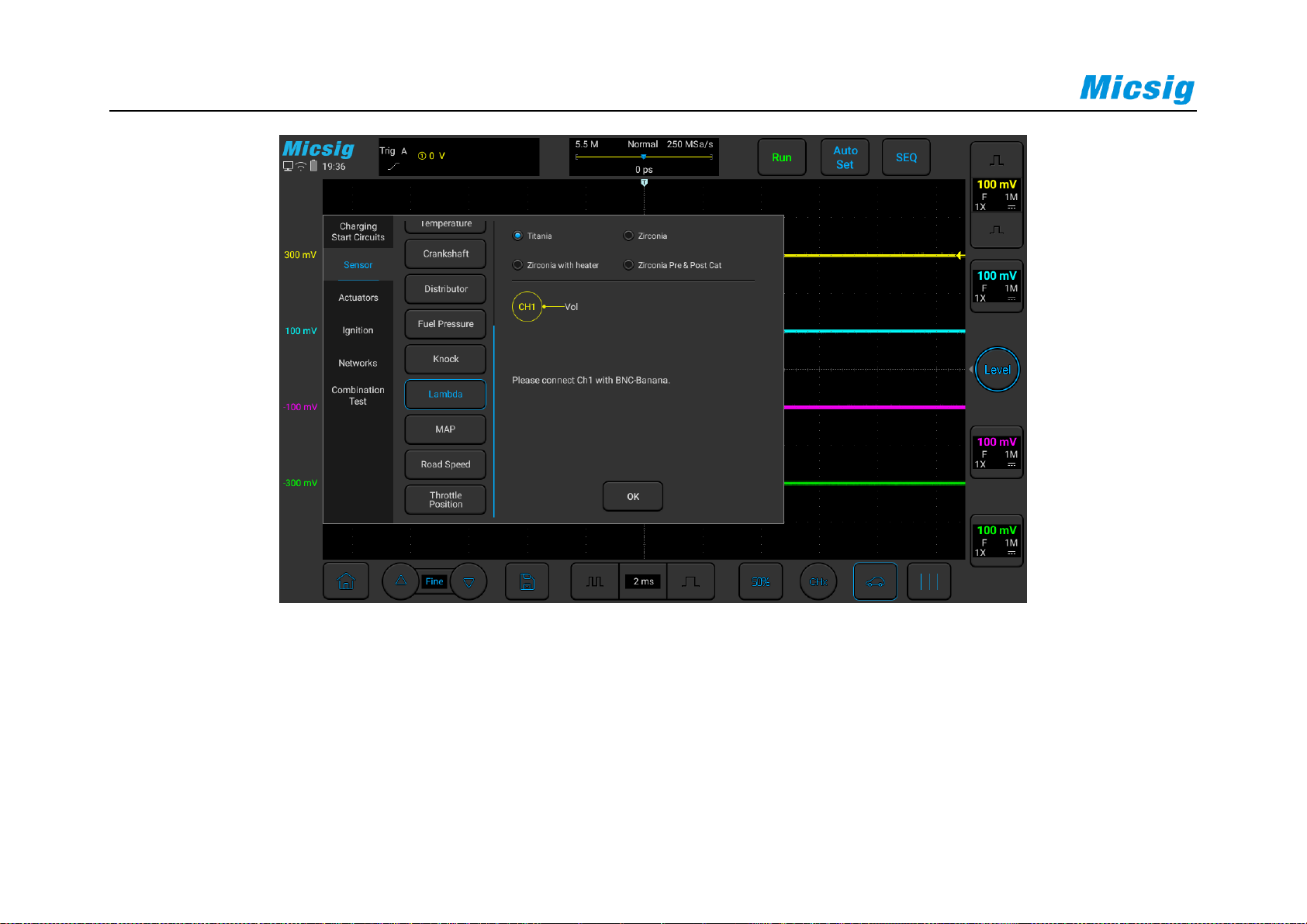
76
Figure 3-20 Lambda (oxygen sensor) test
The following picture is the actual measurement diagram of a certain model of oxygen sensor:
Page 92
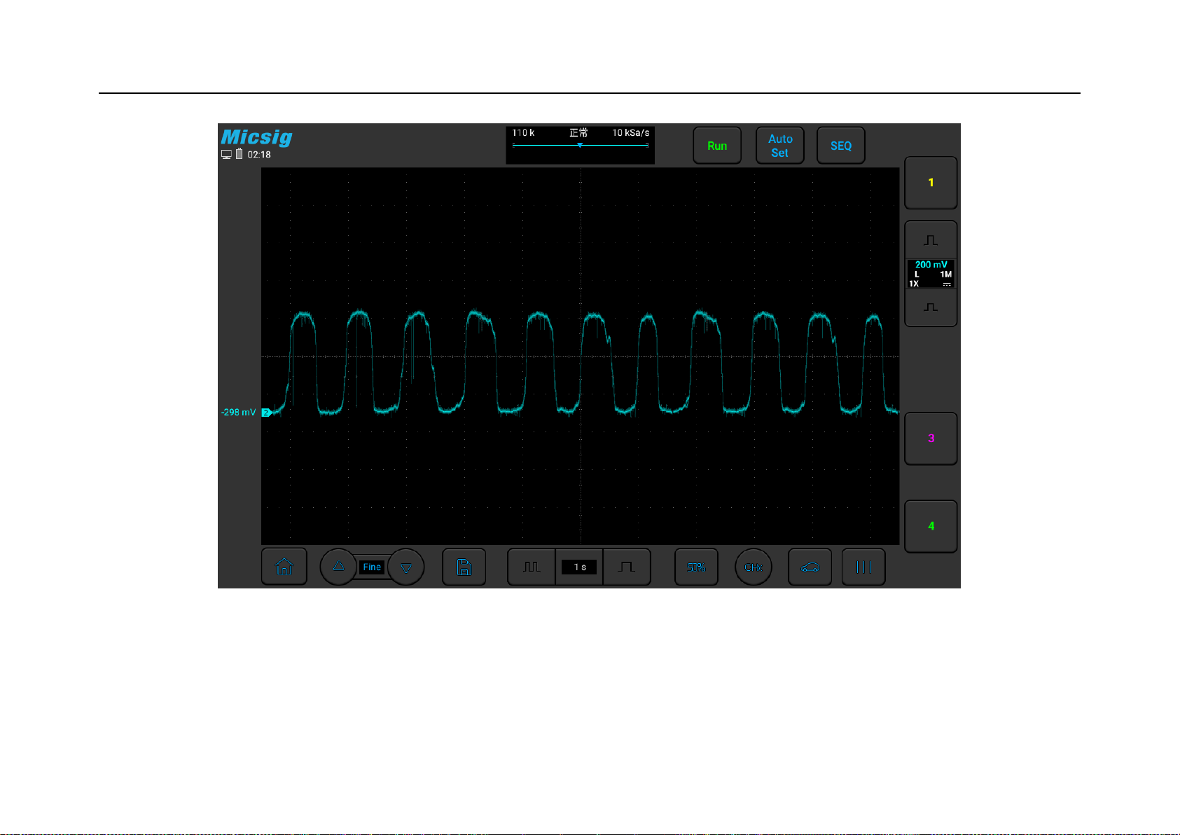
Chapter 3 Automotive Test
77
Figure 3-21 Lambda (Oxygen Sensor) diagram
Page 93

78
3.2.11 MAP
The MAP, or Intake Pressure sensor is used to sense the pressure of the intake manifold and send it to the ECM to
determine the fuel supply, vacuum (or light load), and ignition timing advance angle. There are two kinds of analog
and digital, usually there are 3 wires, power, signal, ground, or together with other devices.
For the analog signal of a gasoline engine, when the throttle is closed or the engine is turned off, the output voltage
is 0, and the output is generally about 1V at idling speed (it may be slightly higher or lower). After quickly
depressing the accelerator, the throttle opens and the voltage rises rapidly. Achieve above 4.5V.
For the analog signal of the diesel engine, the voltage is between 1.5-2.0V at idling speed. After stepping on the
accelerator, the voltage can be seen to rise, which can reach 4.0V.
Use ATO oscilloscope to test the intake pressure sensor, the specific operation is shown in Figure 3-22 below:
Page 94
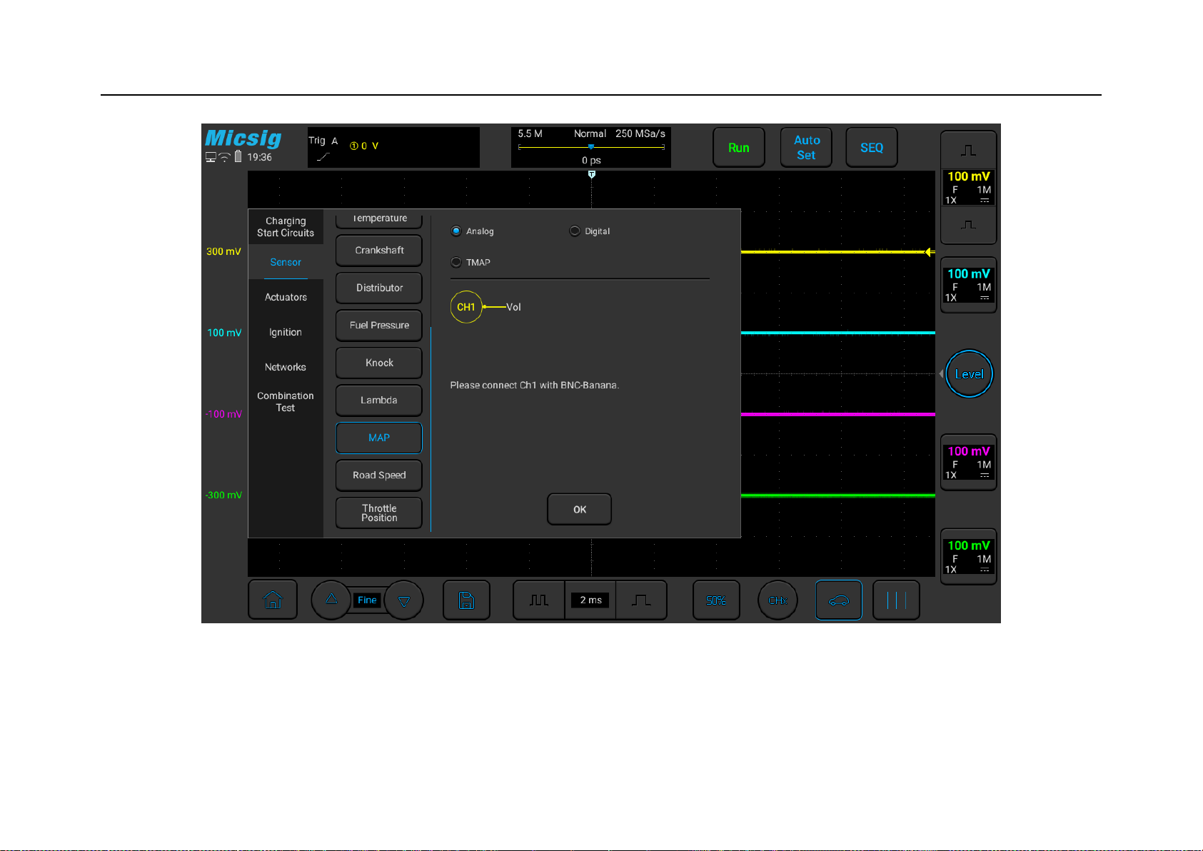
Chapter 3 Automotive Test
79
Figure 3-22 MAP (intake pressure sensor)
Page 95

80
3.2.12 Road Speed
The speed sensor is generally installed on the drive output shaft of the speedometer of the gearbox or near the back
of the head of the speedometer, to provide information for the ECM and monitor power. Usually is Hall type, there
are 3 wires: power, signal, and ground, output square wave signal (some models will be analog, 2 wires, output
inductive signal, sine wave). Use a BNC to banana cable, connect one end to channel 1 of the oscilloscope, the
other end of the black plug is grounded, and the red connector is connected to the signal line of the vehicle speed
sensor with a needle. Lift the vehicle as a whole or lift the driving wheels or connect the signal to a road test, start
the vehicle, put in gear to rotate the wheels, and observe the waveform. The frequency of the square wave increases
with the increase of vehicle speed.
Use ATO oscilloscope to test the vehicle speed sensor, the specific operation is shown in Figure 3-23:
Page 96
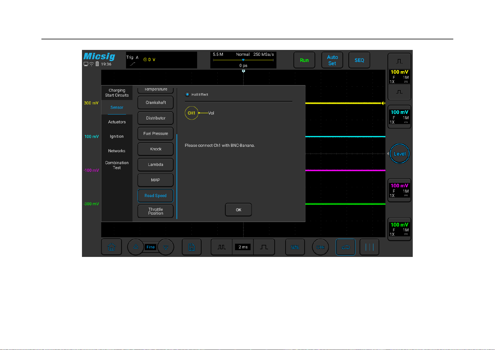
Chapter 3 Automotive Test
81
Figure 3-23 Vehicle speed sensor test
Page 97

82
3.2.13 Throttle Position
The throttle position sensor is installed on the drive shaft of the throttle butterfly plate to sense the opening of the
throttle and provide a basis for ECM to judge the intake. There are analog output and throttle switch output.
Use a BNC to banana cable, connect one end to channel 1 of the oscilloscope, the other end of the black plug is
grounded, and the red connector uses a needle to connect the signal line of the throttle position sensor or the throttle
switch signal 1.
Use a BNC to banana cable, connect one end to channel 2 of the oscilloscope, the other end of the black plug is
grounded, and the red connector uses a needle to connect the signal line of the throttle position sensor, or the
throttle switch signal 2. (if it is a throttle switch, you need to connect this test lead).
Use ATO oscilloscope to test the vehicle speed sensor, the specific operation is shown in Figure 3-24:
Page 98
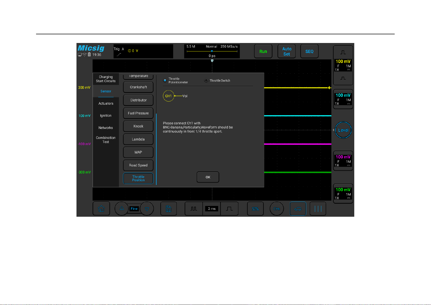
Chapter 3 Automotive Test
83
Figure 3-24 Throttle Position Sensor test
The following figure is the actual measurement diagram of the throttle position sensor of a certain model:
Page 99
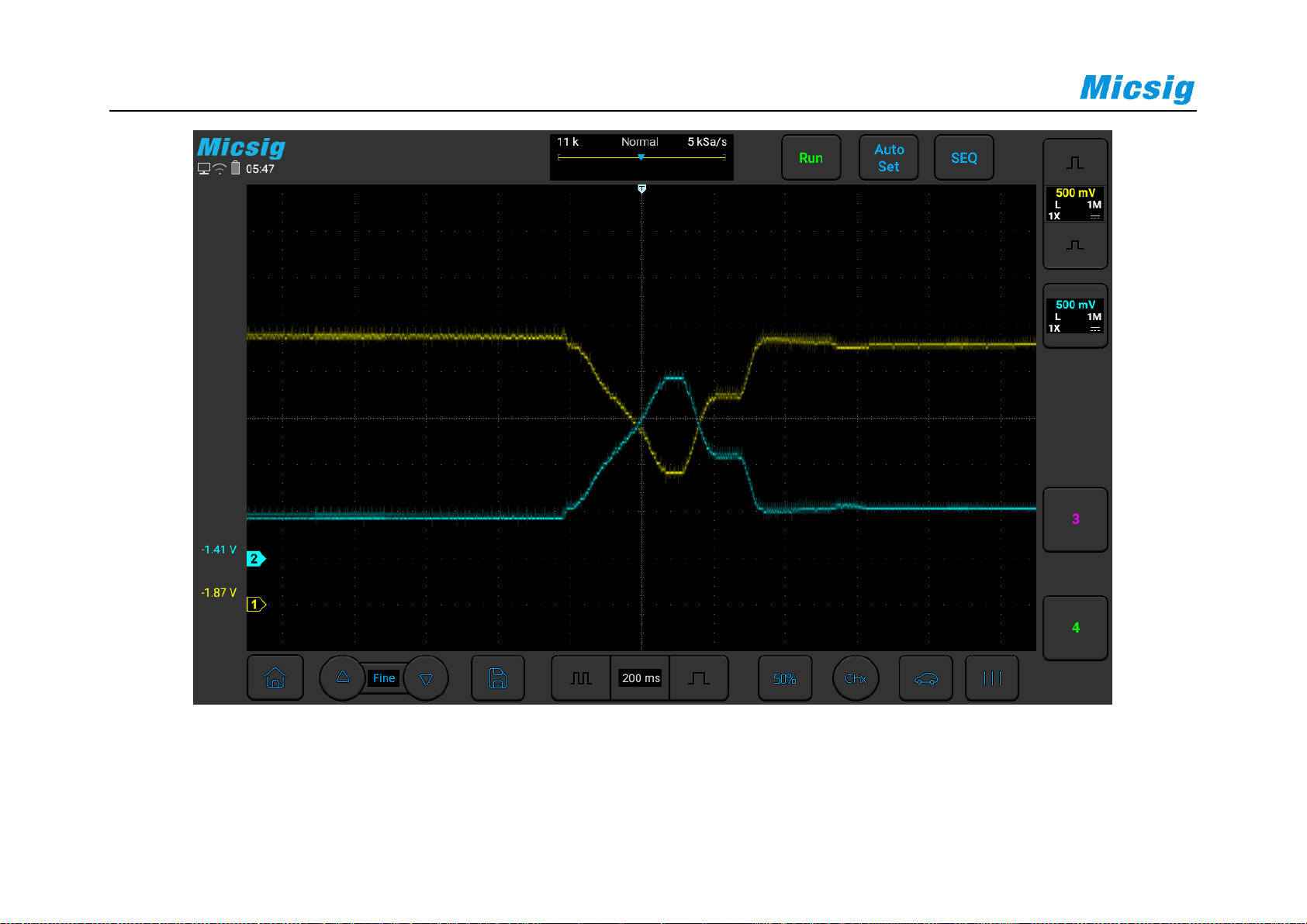
84
Figure 3-25 Throttle Position Sensor Diagram
Page 100

Chapter 3 Automotive Test
85
3.3 Actuators
3.3.1 Carbon canister solenoid valve
The carbon canister is generally installed in the engine compartment and connected to the fuel tank through a pipe
to collect the vaporized oil and gas in the fuel tank, so as to prevent the oil and gas from being discharged into the
air and causing pollution. Use a BNC to banana cable, one end is connected to channel 1 of the oscilloscope, the
other end of the black plug is grounded, and the red connector is connected to the ground wire of the canister
solenoid valve with a needle tip.
Use ATO oscilloscope to test the vehicle speed sensor, the specific operation is shown in Figure 3-26:
 Loading...