

Page 1

)3'7RXFK0RQLWRUV
13.8" and 15.0" Profile and ChassisTouch
,QVWDOODWLRQ*XLGH
Page 2

The information in this document is subject to change without notice. No part of this document may be
reproduced or transmitted in any form or by any means, electronic or mechanical, for any purpose, without the
express written permission of MicroTouch Systems, Inc. MicroTouch may have patents or pending patent
applications, trademarks, copyrights, or other intellectual property rights covering subject matter in this
document. The furnishing of this document does not give you license to these patents, trademarks, copyrights,
or other intellectual property except as expressly provided in any written license agreement from MicroTouch.
© 1998 MicroTouch Systems, Inc. All rights reserved.
Printed in the United States of America.
Document Title: FPD Touch Monitors (13.8" and 15.0" Profile and ChassisTouch) Installation Guide
Document Number: 19-225, Version 2.0
MicroTouch, the Micr oTou ch logo, Ad Link, Chass isTouch, C lea rTek, Drive Point, F actu ra, Fin ePoint, Ib id, the
Ibid logo, K eyPad, Mi crocal , PicturePad, Pri vacyTouch, Prof ile , Pr ospe ctor, The Public Browser, Qui ckPoi n t,
ScreenWriter Tablet, SimpleTouch, SurfControl, ThruGlass, TouchMate, TouchPad, TouchPen, TouchWare,
TouchTek, TruePoint, TuffTouch, UnLink, UnMouse, WebStation, and WorldService are either registered
trademarks or trademarks of MicroTouch Systems Incorporated in the United States and/or other countries.
Microsoft, MS, and MS-DOS are registered trademarks, and Windows is a trademark of Microsoft Corporation.
Page 3

Contents
About This Manual
What You Need to Know.............................................................7
Installation Warnings and Safety Precautions................................ 8
Shock and Fire Hazard Precautions ........................................8
Installation Precautions...........................................................8
Service and Repair Pr ecautions............................................... 9
Sicherheitshinweise und Vorsichtsmaßnahmen............................10
Vorsichtsmaßnahmen zur Vermeidung eines
Funkenschlags oder Stromschlags...................................10
Vorsichtsmaßnahmen bei der Installation.............................. 10
Vorsichtsmaßnahmen bei Wartung und Reparatur.................11
MicroTouch Support Services....................................................12
MicroTouch Technical Support.............................................12
MicroTouch on the World Wide Web...................................13
MicroTouch Bulletin Board System...................................... 13
MicroTouch Corporate Headquarters and Worldwide Offices.....14
Page 4

4 FPD Touch Monitors Installation Guide
Chapter 1 Introduction to Flat-Panel Displays
About Your Flat-Panel Display Touch Monit o r.......................... 16
What Is AM-TFT LCD Technology?......................................... 18
Video Resolution on a Flat-Panel Display................................... 18
Native Video Resolution (1024 x 768)................................. 18
Options fo r Using Other Video Resolutions..........................19
Comparing Video Resolution on a CRT............................... 20
Chapt er 2 Setting Up Your FPD Touch Monitor
System Requirements.................................................................22
Unpacking Your Touch Monitor ................................................ 23
Unique Characteristics of Each Monito r............................... 23
Cables and Accessories........................................................ 24
In stalling th e V ide o Ca rd an d V ide o Drive r................................25
Supported Video Display Modes and Refresh Rates.............25
Configuring the Display Settings..........................................26
Video Cards Tested by MicroTouch.....................................27
Connecting the Touch Monitor..................................................28
Turning On the Touch Monit o r..................................................30
Testing the Touch Monitor ........................................................30
In stalling th e Touchscre en Dr iver...............................................31
In stallin g To uc hWare for
Windows 95 or Windows NT 4.0................................... 31
In stallin g To uc hWare for Win dows 3.1x and MS-DOS ........32
In stallin g To uc hWare for Win dows NT 3.51 ........................33
In stalling Tou chWare for MS-DOS Only .............................. 33
In stallin g To uc hWare for O S/2............................................. 34
Calibrating the Touchscreen.......................................................35
Customizing the Touchscreen Settings.......................................36
Page 5

Chapter 3 Adjusting the Video Display
Guidelines for Adjusting the Display...........................................38
Before You Make Any Adjustments..................................... 38
Using the Standard Controls for t he Video Card ...................38
Controls for Adjusting the Video Display...................................39
Displaying the Menu Options................................................40
Resetting Default Video Values............................................40
Overview of the Menu Options...................................................41
Using the Monitor Adjustment Program.....................................42
Running the Monit o r Adjustment Pro gram in Windows........42
Running the Monit o r Adjustment Pro gram in MS-DOS........42
Exiting fro m the Monitor Adjustment Program.....................43
Adjusting the Clock and Phase Values........................................43
Adjusting the Image Positio n......................................................45
Adjusting the Brightness and Contrast Values ............................46
Adjusting the Whit e Balance......................................................47
Expanding the Image Size..........................................................48
Contents 5
Chapt er 4 Guide lines for Integrating Your FPD Touch Monitor
Mounting the ChassisTouch Monito r..........................................50
ChassisTouch Hardware Accessory Kit ................................ 50
Mounting Options................................................................51
ChassisTouch Cable Connectors...........................................51
Access to the Video Controls...............................................51
Clearance and Ventilation.....................................................52
Securing and Routing System Cables....................................52
Mounting the Profile Monitor to a Wall......................................53
Chapter 5 Maintenance and Troubleshooting
Maintaining Your Touch Monitor...............................................56
Touchscreen Care and Cleaning..................................................56
Monit o r Installation Problems ....................................................57
Troublesho o t ing the Touchscreen............................................... 59
Page 6

6 FPD Touch Monitors Installation Guide
Power Status Light....................................................................60
Power Management ...................................................................61
Video Input Pin Assignment.......................................................62
Appendix A Compliance Statements and Monitor Specifications
Approvals..................................................................................63
Federal Communications Commission (FCC) Statement.......64
Industry Canada Compliance Statement ............................... 65
VCCI Class B ITE Statement...............................................65
Specifications for the 13.8" and 15.0" FPD Touch Monito rs ...... 66
Index
Page 7

About This Manual
Congratulations on the purchase of your touch monitor, and welcome
to the world of MicroTouch — a world where using a computer is as
simple as touching the screen.
This manua l de s cribes how to s et up the follo wing MicroTouc h
TruePoint monitors :
• 13.8" and 15.0" Profile™ flat-panel display (FPD) touch monitors
• 13.8" and 15.0" ChassisTouch™ flat-panel display (FPD) touch
monitors
Sett ing up the touch monitor is easy. This manual descr ibes how to
connect the cables, install the touchscreen software, and adjust the
video display. I t also provides guidelines for integrating the touch
mo nit or into a k iosk or s imilar en closure.
What You Need to Know
Th is d ocu ment assumes you have basic compute r skills. You should
know how to use the mouse and keyboard, cho ose commands fr om
menus , open and r un ap plic ation pr ograms, and save files.
If you need to learn more about these t asks, r e fer t o the manuals and
diskettes that came with your PC.
Page 8

8 FPD Touch Monitors Installation Guide
Installation Warnings and Safety Precautions
Follow all instruc tions marke d on th e p roduct and de scribed in this
!
document. P ay c lose attention to the follo wing installation w arnings
and safety precautions.
Caution:
cover or back o f the monitor. T here ar e no user serviceable par ts
inside. Refer all ser vicin g to qua lified service perso nne l.
Shock and Fire Hazard Precautions
To prevent risk of electric shock and possible fire:
• Do not remove the cover s .
• Always co nnect the power cable to a proper ly wired and grounded
• Always co nnect any equipment used with this monitor to pro per ly
• Always remove the power cable from the socket by holding the
• Do not connect or disconnect this product during an electrical
• Do not place any object on the monitor o r cables that cause t he
To avoid the risk of severe electric shock, do no t remove the
power outlet.
wired and grounded power outlets.
plug, not the cord.
storm.
cables to make sharp bends or that affect the integrity of the
cables.
• Do not place any liquids ( even a wet o r damp cloth) on o r near t he
monitor. Liquids can create an electrical hazard. Do not expose
t he mon itor to rain or moisture.
Installation Precautions
• In stall the displa y in a well-ventilated a re a.
• Use and operate this display from the type of power sour ce
indicated on the AC/DC power supply.
Page 9

About This Manual 9
• Do not use this product near water. Keep the display away fr om
the kitchen, bathroom, washing machine, or o ther sources of
water, steam, or moisture.
• Do not expose this display to direct sunlight or heat. Hot air may
cause damage to the cabinet and other parts.
• Do not install this display in areas where extreme vibrations may be
generated. For example, nearby manufacturing equipment may
produce strong vibr ations. The vibra tions may ca use the d isp lay to
exhibit picture discoloration or poor video quality.
• Do not block ventilation slots and openings with objects or install
the display in a place where ventilation may be hindered. Always
maintain adeq ua te ventilatio n to prote ct the display from
overheating and to ensure reliable and continued operation.
• Do not allow metal pieces or objects of any kind to fall into the
display ventila tion holes.
• Handle the display with care. T he display contains glass parts.
Dropping the display may cause the glass parts to break.
Service and Repair Precautions
Do not attempt to service this unit yourself. Removing the display
cover may expose you to dangerous voltage or other risks. Refer all
se rvicing to q ua lified service pe rs onne l.
Unplug the display from the power outlet and refer servicing to
qualified service personnel in t he event that:
• Liq uid is spilled in to the product or the p roduct is exposed to ra in
or water.
• The product does not operate pr operly when the operating
instru ctions are followed.
• The product has been dropped or the cabinet has been damaged.
• The product exhibits a distinct change in performance, indicating a
need for service.
• The power cable or plug is damaged or frayed.
Page 10

10 FPD Touch Monitors Installation Guide
Sicherheitshinweise und Vorsichtsmaßnahmen
Befolgen Sie die Hinweise auf dem Produkt und in dieser
!
Dokumentation. Lesen Sie die folgenden Sicherheitshinweise und
Vo rsicht smaßna hmen s orgfältig d urch.
Warnung:
Sie nicht die Abdeckung oder Rückwand des Monitors. Das Gerät
enthält keine Teile, die vom Kunden repariert werden können. Überlassen S ie s ä mtliche Rep araturen geschultem Kund e ndienst pers onal.
Vorsicht smaßnahmen zur Vermeidung eines
Funkenschlags oder Stromschlags
Um die Gefahr eines Funkenschlags oder St r omschlags zu vermeiden,
beachten Sie folgende Punkte:
• Entfernen Sie keine Abdeckungen.
• Schließen Sie das Netzkabel grundsätzlich an eine ordnungsgemäß
installierte un d geer de te S tromquelle an.
• Schließ en Sie alle mit dies e m Monitor verbu ndenen G e räte
gru ndsätzlich an eine or dnungsgemäß installier te u nd geerdete
Stromq ue lle a n .
• Ziehen Sie das Netzkabel grundsätzlich am Stecker und nicht am
Kabel aus der Steckdose.
• Schließ en Sie da s Gerät nicht wä hrend eines Gewitter s a n bzw.
trennen S ie es währenddessen nicht vom Netz.
Um die Gefahr eines Stromschlags zu vermeiden, entfernen
• Stellen Sie keine Gegenstände auf den Monitor oder die Kabel,
und vergewissern Sie sich, daß die Kabel nicht geknickt werden.
• Halten Sie Flüssigkeiten (auch ein nasses oder feuchtes Tuch) vom
Gerät fern, und setzen Sie es nicht Regen o der Feuchtigkeit aus, da
sons t die Gefahr eines Stromschlags besteht.
Vorsichtsmaßnahmen bei der Installation
• In stallier en Sie da s G er ät an ein em g ut belüfteten Ort.
• Vergewissern Sie sich, daß I hre St r omquelle den Angaben auf dem
Netzadapter ent spricht.
Page 11

About This Manual 11
• Halten Sie das Gerät von Wasser fern. Stellen Sie es daher nicht in
Küche oder Badez immer bz w. in d er Nähe ein er Wa schmasch ine
oder anderer Wasser-, Dampf- bzw. Feuchtigkeitsquellen auf.
• Setzen Sie den M onitor nicht dir e kter S onnene instrahlung oder
Hitze aus. Das Gehäuse und andere Teile können durch Hitze
beschädigt werden.
• In stallieren Sie das Gerät nic ht an Orten , an d enen es extremen
Schwingungen ausgesetzt sein könnte, wie z.B. in der Nähe von
Fertigungsanlagen. Die Schwingungen können zu schlechter Farbund Bildwiedergabe führen.
• Blockieren Sie die Lüftungsschlitze und Öffnungen nicht, und
sorgen Sie für eine gute Belüftung, um Überhitzung zu vermeiden
und e inen z uverläs s igen und be stä ndigen Be tr ieb z u gew ährleisten.
• Lassen Sie keine Met allteile oder andere Gegenstände in die
Lü ftungsschlitze de s Ger äts fallen.
• Gehen Sie vorsichtig mit dem Gerät um. Es enthält zerbrechliche
Teile aus Glas.
Vorsicht smaßnahmen bei Wartung und Reparatur
Versuchen Sie nicht, das Gerät selbst zu warten. Wenn Sie die
Abdeckung entfernen, können Sie ge fä hrlicher S pannung und anderen
Gefahren ausgesetzt werden. Lassen Sie alle Wartungsarbeiten von
einem geschulten Kundendiensttechniker ausführen.
Trennen Sie in den nachstehend aufgeführten Fällen das Gerät vom
Netz, und lassen Sie es von einem qualifizier ten Kundendienst techniker
überprüfen:
• Flüssigkeit ist in das Gerät gelangt, bzw. das Gerät ist naß
geworden.
• Trotz Beachtung der Hinweise in der Bedienungsanleitung
funktioniert das Gerät nicht ordnungsgemäß.
• Das Gerät ist gestürzt bzw. das Gehäuse wurde beschädigt.
• Das Gerä t weist eine vermind erte L eistung auf.
• Das Netzkabel oder der Stecker ist beschädigt bzw.
durchgescheuert.
Page 12

12 FPD Touch Monitors Installation Guide
MicroTouch Support Services
MicroTouch provides extensive support services through our t echnical
support organization, web site, and bulletin board system (BBS).
MicroTouch Technical Support
Technical Support is available as follows:
• 24 hours a day, Monday through Friday (excluding holidays)
• 9:00 a.m. to 5:00 p.m. Eastern Standard Time, Saturday and
Sund ay (excluding holidays)
Whenever you contact Technical Support, please provide the
fo llowing info rmat ion :
• Part number and serial number from the MicroTouch label on your
monitor
• Version number of your MicroTouch TouchWare
• Make and model of your personal computer
• Name and version number of your op er ating system
• Type of mouse connected t o your system
• List of other peripherals connected to your computer
• List of ap plic ation s oftware in use
You can contact MicroTouch Technical Support by calling the hot line,
sending a fax, or sending electronic mail.
• Technical Support Hot Line: 978-659-9200
• Technical Support Fax: 978-659-9400
• Technical Support E-Mail: support@micr otouch.com
Page 13

About This Manual 13
MicroTouch on the World Wide Web
You can visit the MicroTouch web site at the following address:
http://www.microtouch.com
You can download MicroTouch touchscreen software and drivers,
obtain regularly updated technical information on MicroTouch
products, and learn more about ou r company.
MicroTouch Bulletin Board System
MicroTouch also has a Bulletin Board System (BBS) that you can
access 24 hours a day, 7 days a week. You can use the BBS to
download updates of the latest drivers and obtain regularly updated
technical information on MicroTouch products.
You can reach the MicroTouch BBS at the following nu mbers:
• 978-659-9250
• 978-683-0358
To connect to the BBS, you need standard communication software
and a modem that supports 2400, 4800, 9600, 14400, or 28800 baud.
Additionally, the communication parameters must be set as follows:
No parity, 8 data bits, and 1 stop bit (N81)
Once you establish a modem connection with the BBS, the system
prompts you to log in using your name. You can register with
MicroTouch the first time you log in to the BBS . The menu of
available options is self-explanatory.
Page 14

14 FPD Touch Monitors Installation Guide
MicroTouch Corporate Headquarters and Worldwide Offices
United States
MicroTouch Systems, Inc.
300 Griffin Brook Park Drive
Methuen, MA 01844
United States
Phone: 978-659-9000; Fax: 978-659-9100
Web Sit e: ht tp://www. mi c rotouc h.com
E-Mail: [email protected]
Support Hot Line: 978-659-9200
Support Fax: 978-659-9400
Support E-Mail: [email protected]
Australia
MicroTouch Australia, Pty Ltd.
797 Springvale Road
Mulgrave Victoria 3170 Australia
Phone: +61 (03) 9561 7799
Web Sit e: ht tp://www. mi c rotouc h.com.au
E-Mail: [email protected]
Support:
France
MicroTouch Systems SARL
Europarc de Créteil
19, rue Le Corbusier
94042 Créteil Cedex France
Phone: +33 (1) 45 13 90 30
Support:
Germany
MicroTouch Systems GmbH
Schiess-Str. 55
40549 Düsseldorf Germany
Phone: +49 (0) 211-59907-0
Support:
Hong Kong
MicroTouch Systems, Inc.
Unit D, 9/F, Trust Tower
68 Johnston Road
Wanchai, Hong Kong, China
Phone: +852 2333 6138; +852 2334 6320
Italy
MicroTouch Systems srl
C.so Milano, 19
20052 Monza (MI) Italy
Phone: +39 (0) 39-230-2230
Support:
Japan
MicroTouch Systems K.K.
Bellevue Mizonokuchi Building 3F,
3-2-3, Hisamoto, Takatsu-ku,
Kawasaki-shi, Kanagawa 213 Japan
Phone: +81 (044) 811-1133
Korea
MicroTouch Systems, Inc.
#402, 4
th
Floor, Nam-Kyung Building
769-6 Yeoksam-Dong, Kangnam-Gu
Seoul, Korea
Phone: +82 (2) 552-3198
Spain
MicroTouch Systems SL
Via Augusta 13-15, Oficina 607
08006 Barcelona Spain
Phone: +34 (9) 3415 6285
Support:
Taiwan R.O.C.
MicroTouch Systems, Inc.
3F-12, No. 351, Chung Sha n Road, Sec. 2
Chung Ho City, Taipei
Taiwan R.O.C.
Phone: +886 (02) 2226-0875
United Kingdom
MicroTouch Systems, Ltd.
163 Milton Park
Abingdon
Oxon OX14 4SD England
Phone: +44 (0) 1235-444400
BBS: +44 (0) 1235-861620
Support:
Page 15

CHAPTER 1
Introduction to Flat-Panel Displays
The MicroTouch pro duct line of Flat-Panel Display (FPD) touch
monitors offers the TruePoint Profile monitor for the desktop and the
ChassisTouch monitor for kiosk, ATM, and industrial enclosures.
The monitors ar e available in a variety of sizes. T his chapter
introduces the 13.8" and 15.0" Profile and ChassisTouch monitors,
and p rovides the following info rma tion :
• Features and benefits of your MicroTo uch FPD monitor
• Overview of flat-panel display technology
• Video resolution on a flat-panel display
Page 16
16 FPD Touch Monitors Installation Guide
About Your Flat-Panel Display Touch Monitor
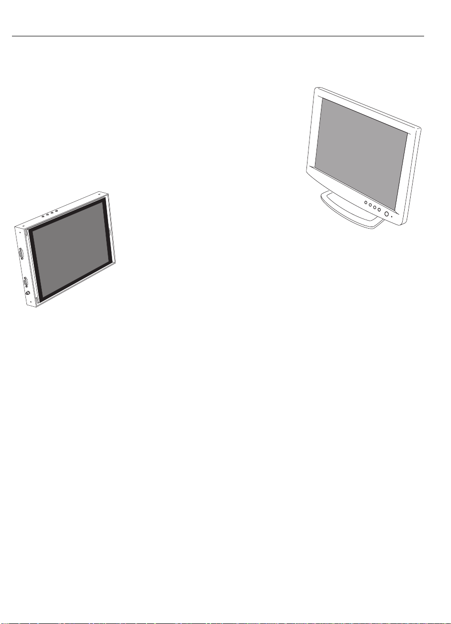
The MicroTouch pro duct line of FPD
touch monitors includes deskt op models
and chassis models.
The Profile™ flat-panel display is a
desktop touch monitor that features a
sleek design with a small footprint.
The ChassisTouch™ flat-panel
display is designed specifically
for kiosks and other enclosures.
All ChassisTouch monitors ar e
encased in rugged metal instead
of plastic.
The Profile and ChassisTouch monitors feature a
ChassisTouch
FPD
touchscreen interface, several mounting options, and sturdy
construction. Table 1 lists the benefits of these features.
MicroTouch
Profile FPD
The Profile and ChassisTouch monitors are available in a variety of
diagonal screen sizes, including 13.8" and 15.0". The flat-panel
display use s active- matr ix thin-film transis tor (AM -TFT) liquid
crystal display technology. The 13.8" and 15.0" monitors support a
full-screen resolution of 1024 x 768.
The monitors ar e available with either MicroTou ch’s ClearTek®
capacitive touchscreen or T ouchTek™ 5-wire resistive touchscreen –
making them suitable for the widest spectrum of to uch applications.
Sample a pp lica tion s include multime dia kiosks for gove rnment,
financial, retail, a nd point-of-information markets, wall-mou nted P OS
stations, ticketing booths, and industrial enclosures.
The monitors also feature space saving designs, high resolution, high
brightness, low radiation, and low power consu mption. These
qualities make the FPD touch mo nito rs ide al for ap plic ations th at
require color, resolution, and clarity.
Page 17

Chapter 1 Introduc tion to Flat-Panel Displays 17
Table 1. Pr ofile and ChassisTouch Features and Benefits
Features Benefits
Active-Matrix TFT Liquid Crystal
Display techno logy
• Provides wide viewing angle performance
with exceptional brightness, contrast, and
sharpness
• Provides high switching speed and large
color depth making the display ideal for
t oda y’s multimedia imag es
Profile : s lee k d esign, low profile ,
and small footprint
ChassisTouch: metal enclosed
display; no bezel
Re quires su bstantia lly less counter top or
desktop space than traditional CRTs
Provides easy integration of FPD touch
monitors into kiosks and industrial enclosures
Flat display Provides increased viewing area over
t radition al curved displa ys ( CRTs)
Touchscreen interface
• Makes your application intuitive and easy
to use – simply touch the screen
• Requires less employee training
• Requires no keystrokes or difficult
comma nds to r emember
• Requires no keyboard, mouse, or pad
Variety of mounting options Makes the monitor adaptable to a variety of
markets and applications
Profile : c ast-iron base an d friction
Provides added stability during tou ch in put
hinges
ChassisTouch: cable connectors exit
Provides added installation options
from side or bottom of chassis
Page 18

18 FPD Touch Monitors Installation Guide
What Is AM-TFT LCD Technology?
The MicroTouch flat-panel displays use active-matrix thin-film
transistor (AM-TFT) liquid cr ystal display (LCD) technology.
With AM-TFT LCD technology, a flat-panel display shows a video
image b y us in g a matrix (r ows by columns ) of tiny liqu id c rystal cells.
The cells create the pixels (picture elements) that make up the image.
To be more exact, a cell actually exists for each color of each pixel on
the display. Each pixel is made up of three colors, or sub-pixels (red,
green, and blue).
Each cell ha s a thin-film transistor switch to tur n a pixe l on o r off.
Th e a b ility to tur n on a sing le p ixel and turn off its neighboring p ix els
results in an image with exceptional contrast and sharpness. Also, the
t hin-film tr ansistors let the sys tem a dd ress an d c on trol each sub-pixel
ind iv idually. The result is a fast r es ponse time in displayin g the image.
Video Resolution on a Flat-Panel Display
Flat-panel displays, unlike CRTs, are optimized to run at one
resolution. A flat-panel display has discrete points on the display that
determine the exact location of a pixel. Each flat-panel display has an
exact number of pixels associated with it. There is a one-to-one
mapping b etw ee n the n umber of pixels and the video add ressab ility,
some times ca lled resolutio n.
Native Video Resolution (1024 x 768)
A flat-panel display is intended to be used only at the resolution
dictated by the number of pixels on the panel. For example, the 13.8"
and 15.0" Profile and ChassisTouch monitors have 1024 pixels across
the screen and 768 lines of pixels down the screen. Therefore, these
flat-panel displays can accurately display one resolution (1024 x 768)
at full screen.
Page 19
Chapter 1 Introduc tion to Flat-Panel Displays 19
Options for Using Other Video Resolutions
The MicroTouch 13.8" and 15.0" Profile and ChassisTouch monitors
have a 1024 x 768 (XGA) flat-panel display.
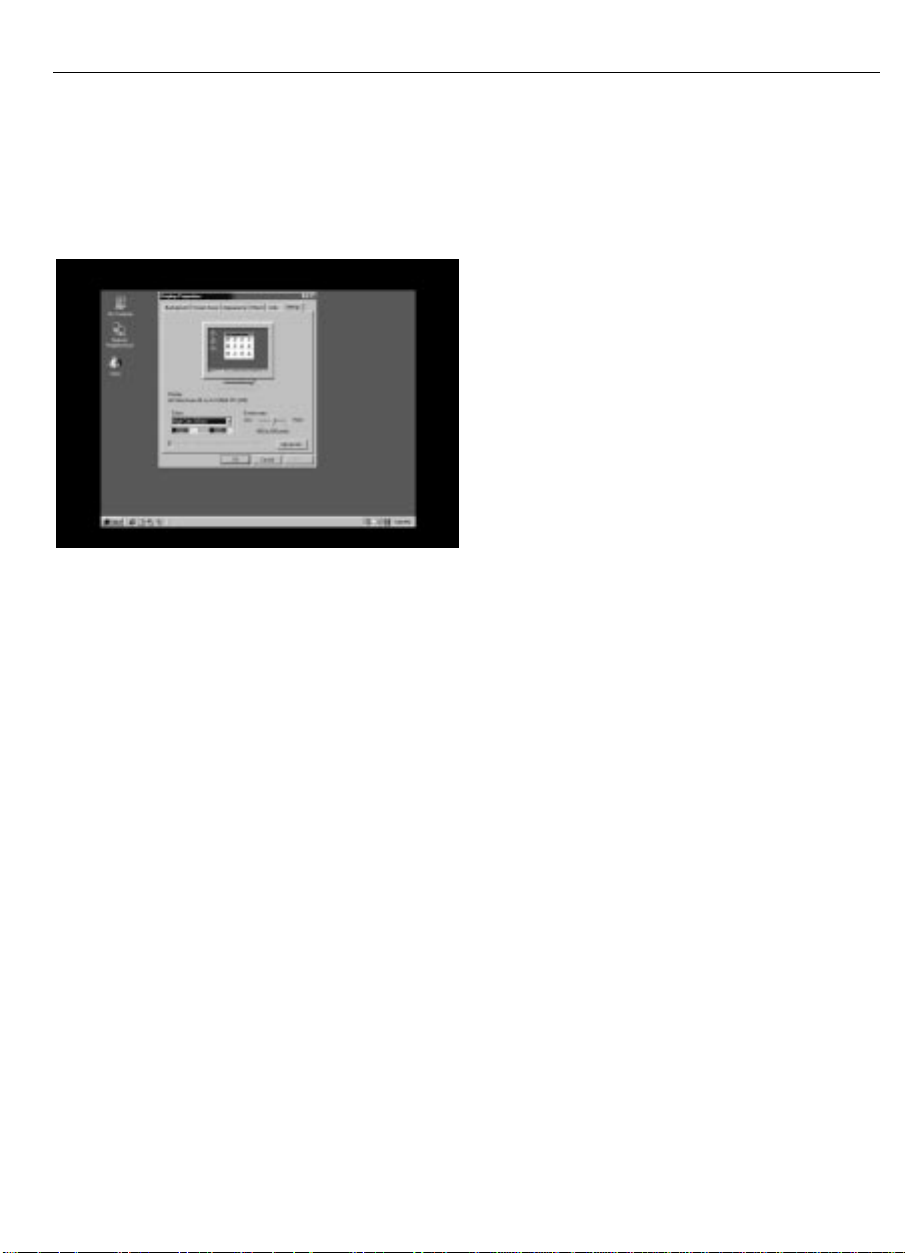
If you use a resolution that is less than
the number of pixels res ident on the
flat-panel d isplay, the monito r will sh ow
t he image u sing only the total numb er o f
pixels generated by the source. For
example, the monitor uses only 800
pixels across and 600 lines of pixels
down the screen when displaying an
SVGA (800 x 600) resolution. The
remaining pixels are n ot used . In th is
case, the monitor preserves t he image
quality, but do es not use th e e ntire screen. Y ou w ill see a h igh-quality
image centered in the display and surrounded by a black border of
unused pixels.
You can use the monitor’s on-screen contr ols to expand the image to
fill t he entire screen. To fill a 1024 x 768 flat-panel, the monitor
expands an 800 x 600 resolution by 1.25 and a 640 x 480 resolution
by 1.6. In both cases, the monitor spreads fewer pixels of information
across a larger number of pixels. Although this technique produces an
image th at fills the entire screen , the ima ge will be distor ted . The
pixels will ta ke on a b roa der or fuzz ier ap pe ar ance.
The MicroTouch 13.8" and 15.0" FPD monitors support t he 800 x 600
(SVGA) and 640 x 480 (VGA) resolutions primarily for compatibility
and monitor setu p. Many vide o ca rds initially d isp lay a scre en imag e
at the SVGA or VGA resolution. By supporting these resolutions, the
monitor can display the desktop controls that let you change to the
optimal resolution of 1024 x 768.
Page 20

20 FPD Touch Monitors Installation Guide
Comparing Video Resolution on a CRT
The CRT is an analog device. There are no discrete po ints on t he
screen that const itute a pixel. Instead, a CRT has a smooth phosphor
surface inside the tube. CRT technology uses an electron beam to
stimulate the phosphor surface to emit light and display an image. The
location of points on the screen is determined by the coordinate system
in which the electron beam is working — not by physical constraints
used on the front surface of the display. As a result, a CRT can
display differen t resolutions without compromising ima ge quality.
Page 21

CHAPTER 2
Setting Up Your FPD Touch Monitor
This chapter describes how to set up your MicroTouch FPD touch
monitor. You need to complete the following tasks:
• Unpack the components
• Check that a video card and the video software driver are already
installed in your sys tem
• Connect the video, touchscreen, and power cables
• Power on the monitor and test your setup
• Install the touchscreen software
• Calibrate the touchscreen
Page 22

22 FPD Touch Monitors Installation Guide
System Requirements
The Profile and ChassisTouch flat-panel touch monitors require a
personal computer (PC). These touch monitors are not supported on
Macintosh computers.
The requirements for your PC are as follows:
• Your PC must have an available RS-232 serial communication
(COM) port. You connect the to uchscreen to this port.
• Your PC must have a unique interrupt request (IRQ) available to
t he COM port that the touchs creen will use. The touchscre en
cannot share an IRQ with another device.
• If the only serial port available on your PC has 25 pins, you will
need a 9-pin to 25-pin adapter.
• Your PC must have a video card and video driver already installed
for the monitor. If you need to install a video card o r a video
driver, refer to your computer do cumentation for instructions.
• Th e vide o card must be compatib le w ith the dis pla y timin gs listed
in T able 2 .
When choosing your work space, select a stur dy, level surface. Also,
make sure you can easily access the back of the touch monitor and t he
computer. E asy access helps ensure a smooth setup of the t ouch
monitor.
Note:
Before setting up your touch monitor, refer to the “Installation
Warnings and Safety Precautions” section at the beginning of this
document.
Page 23
Chapter 2 Setting Up Your FPD T ouc h M onitor 23
Unpacking Your Touch Monitor
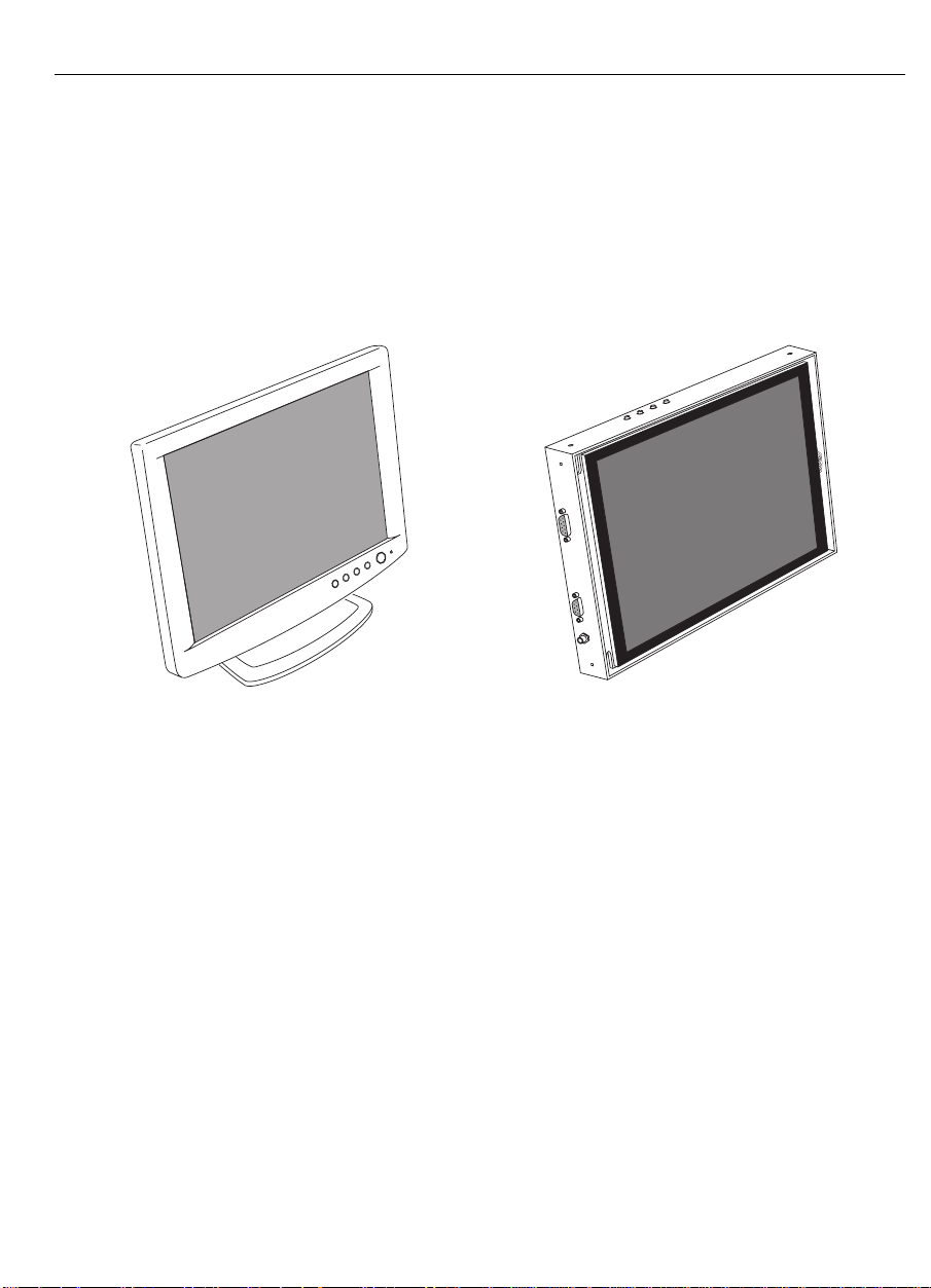
Carefully unpack the carto n and inspect the contents. Yo ur package
may include the flat-panel desktop model or the chassis model.
Identify your flat-panel display. Additionally, make sure you received
the cables and accessories listed in the following sections.
MicroTouch
Profile De sk top
Flat-Panel Display Touch Monitor
Unique Characteristics of Each Monitor
Note the following features of each monitor:
• The Profile monitor has a power button and a po wer L ED on its
front panel. The Chas s isTouch monitor does not have a p owe r
button o r a power LED. The power is on when you plug in the
power cable.
• Each monitor has four but tons for using the on-screen menu and
adjusting the video display. Refer to Chapter 3 for more
information on these contr ols.
• The cable connectors on t he ChassisTouch monitor may be
mounted either on the side or on the bottom of the unit, depending
on the model you have.
ChassisTouch
Flat-Panel Display Touch Monitor
Page 24
24 FPD Touch Monitors Installation Guide
Cables and Accessories
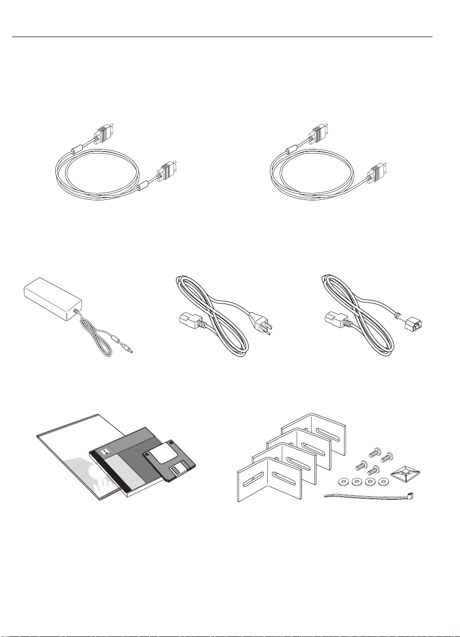
Your t ouch monitor includes the following cables and accessories:
SVGA video cable
(15-pin, mini D-s ub co nnect or )
RS-232 serial communication cable
(connects t he t ouchscreen to the serial
COM port in your computer)
AC/DC power supply AC power cable IEC to I E C power cable
(12V DC output)
FPD Touch Monitors
Profile and ChassisTouch
Installation Guide
TouchWare
MicroTouch
Supports:
Windows
MS-DOS
OS/2
Macintosh
Includes:
Documentation
Disk Creat ToolDisk Creat Tool
May 1998
LCD MONITOR DISK
Display Selection and
OSD Adjusting Procedure
Installation guide, TouchWare CD with
touchscreen software and documentation,
and LCD Monitor diskette with software
for adjusting the video display
ChassisTouch hardware kit
(include s mounting bra ckets, s crews,
washers, cable tie, and cable mount)
Page 25

Chapter 2 Setting Up Your FPD T ouc h M onitor 25
Installing the Video Card and Video Driver
Before you can connect your to uch monitor, make sure your computer
has a video card already installed for the monitor. After you connect
the monitor, you need to install the video software driver. The video
driver is supplied by the video card manufacturer and may be found on
the diskettes that came with your computer.
If you need information on in stalling a video card or vide o dr iver, refe r
to the manual that came with your video card.
Supported Video Display Modes and Refresh Rates
Your video card must support o ne of the display modes specified in
Table 2. If yo u select an unsupported video mode, the monitor will
stop wo r king or display unsatisfactory picture quality.
The 13.8" and 15.0" Profile and ChassisTouch monitors have a
1024 x 768 flat-panel display. The ideal settings for these monitors are
as follows:
• Display Mode: 1024 x 768
• Refresh Rate: 60 Hz
• Color Depth: at least 16-bit (high color)
The 13.8" and 15.0" FPD monitors also support 800 x 600 (SVGA)
and 640 x 480 (VGA) resolutions. They suppo r t these resolutions
prima rily for compatibility an d monitor setu p. Many vide o cards
initially dis pla y a screen ima ge at the SVGA or VGA re solution. By
supporting these resolutions, the monitor can display the desktop
contro ls that let you change to the optimal resolution of 1024 x 768.
Page 26

26 FPD Touch Monitors Installation Guide
Table 2. Applicabl e Display Mode, Video Timing, and Expansion Rates
Display Mode H Sync V Sync
(Refresh Rate)
VGA
(640 x 480)
SVGA
(800 x 600)
XGA
(1024 x 768)
DOS Text
(720 x 400)
31.5 kHz
37.9
37.5
35.1
36.9
48.1
46.9
48.4
56.5
60.0
31.5 70 28.3 1.4 A 720 x 400
60 Hz
72
75
56
60
72
75
60
70
75
Configuring the Display Settings
After you connect your monitor and turn on your computer, you may
need to co nfigure one or more of the following display settings:
Dot
Frequency
25.175 Mhz
31.5
31.5
36.0
40.0
50.0
49.5
65.0
75.0
78.75
Expansion
Rate
1.6
1.6
1.6
1.25
1.25
1.25
1.25
1.0
1.0
1.0
When No
Expansion
A 640 x 480
image is centered
within the screen.
An 800 x 600
image is centered
within the screen.
Not applicable.
image is centered
within the screen.
•
Dis play mo de (also called de sk top a re a or vid eo resolution )
•
Refresh rate (also called vertical scan rate or vertical sync)
•
Color dep th (also called color palette or numb er of colors)
Each video card has several controls that let you adjust the display
settings. However, the software and driver for each video card is
unique. In most cases, you adjust t hese set tings by using a program or
utility pr ov ide d by th e ma nufacturer of the video card.
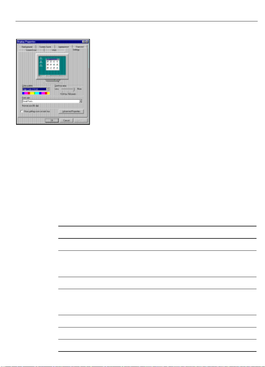
Most video cards use the Windows Display P r opert ies contr ol panel to
configure the display. The Settings tab usually lets you change the
Color Palette and the Desktop Area (x by y pixel r esolution).
Page 27
Chapter 2 Setting Up Your FPD T ouc h M onitor 27
Some video cards integrate additional features into the
Window s Display Proper ties c ontrol pane l to give you
an exceptional setup that is flexible and easy to use. Fo r
example, the contro l panel may include an Advanced
Properties button, an Adjustment tab, or a Refresh tab
for changing other s ettings. Other video c ard s ha ve a
se pa rate utility for setting displa y proper ties.
Whenever you change the resolution, color, or r efresh
rate, the image size, position, or shape may change.
This behavior is normal. You can readjust the image
us ing th e monitor con trols. F or more in forma tion on the monitor
controls, refer to Chapter 3. For more information on configuring the
display settings, refer to the manual that came with your video card.
Video Cards Tested by MicroTouch
MicroTouch reviewed and tested several video cards current ly
available in the PC marketplace. Table 3 provides a partial listing of
the video cards compatible with the Profile and ChassisTouch FPD
touc h monitors.
Table 3. Video Cards Compatible with the M icroTouch F P D M onitors
Company Model Chip Set
ATI Technologies Xpert@Work ATI 3D Rage Pro Turbo
Diamond Stealth II G460
Stealth 3D 2000 Pro
Viper V330
Genoa V-Raptor 3D Rendition Verite V2200
Matrox Millenium
Mystique G200
Productiva G100
Number 9 Revolution 3D Ticket to Ride
STB Systems, Inc. Velocity 128 3D NVidia Riva 128
Symmetric Glyder Max-2 Permedia 3D Labs
Intel 740
S3 Virge GX
NVidia Riva 128
MGA 64-bit graph i cs
MGA 64-bit graph i cs
MGA 64-bit graph i cs
Page 28
28 FPD Touch Monitors Installation Guide
1
2
3
4
5
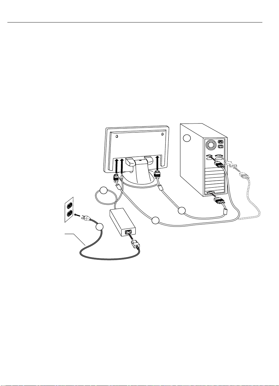
Connecting the Touch Monitor
To co nnect the touch monitor:
1. Turn off your computer. You should always turn off the computer
before connecting or disconnecting a device.
2. Connect one end of the video cable to the video connector on t he
monitor. Connect the ot her end to the video card in your
computer.
AC power cable
3. Connect one end of the RS-232 serial touchscreen cable to t he
monitor . Connect the other end to an available serial
communication (COM) port on t he back of your computer.
• If the COM port has a 9-pin connector, attach t he t ouchscreen
cable dir ectly to the port.
• If the COM port has a 25-pin connector, first att ach a 9-pin to
25-pin adapter (not included) to the end of the touchscreen
cable, and then attach the cable to the po r t.
Page 29
Chapter 2 Setting Up Your FPD T ouc h M onitor 29
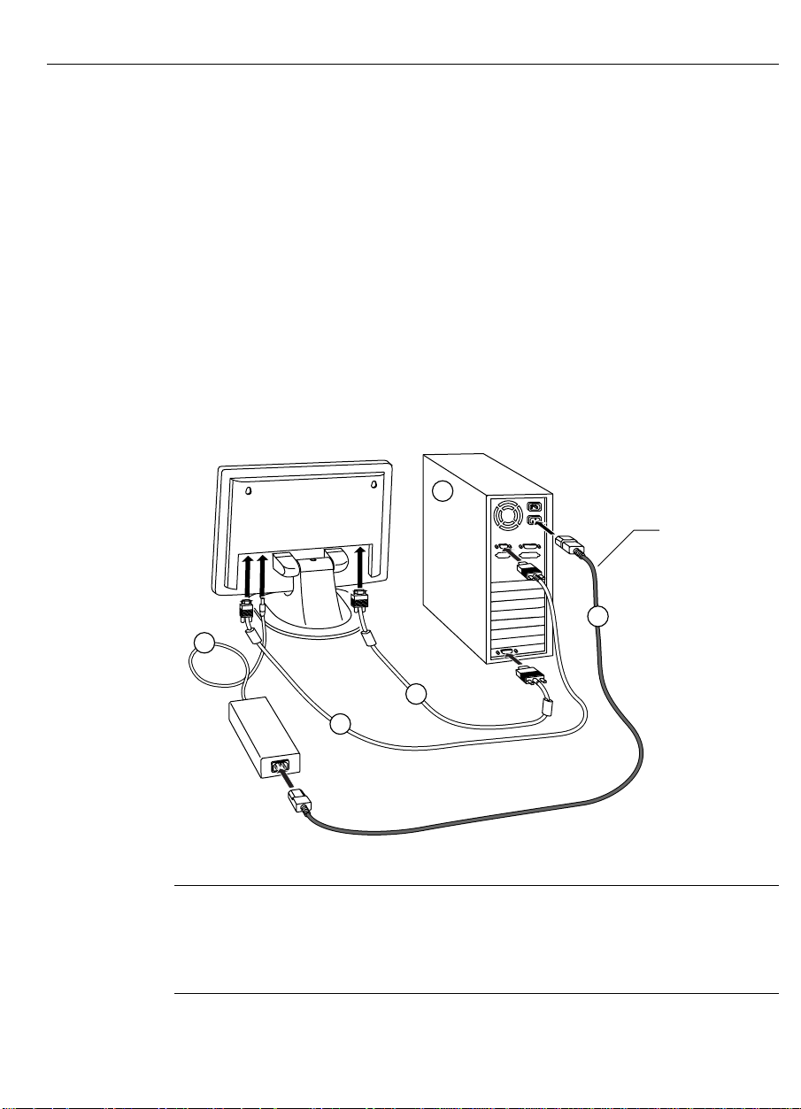
4. Plug the AC/DC power supply into t he monitor.
5. Connect the power cable.
Note that your to uch monitor includes an AC power cable and an
IEC to IEC power cable.
• If you are using the AC power cable, plug one end of the
cable into the AC/DC power supply. Plug the other end into a
prop er ly grounded power outlet. (Refer t o the illustra tion o n
the previous page.)
• If you are using the IEC cable, plug one end of the cable into
the AC/DC power supply. Plug the ot her end into the out let
o n the back of your PC. ( Ref er to the illus tration below.)
1
IEC to IEC
power cable
5
4
2
3
Note:
If you are setting up a ChassisTouch monitor, the connector s
for the to uchscreen, power , and video cables may be mounted either
on the side or on the bott om of the unit, depending on the model you
have.
Page 30
30 FPD Touch Monitors Installation Guide
Turning On the Touch Monitor
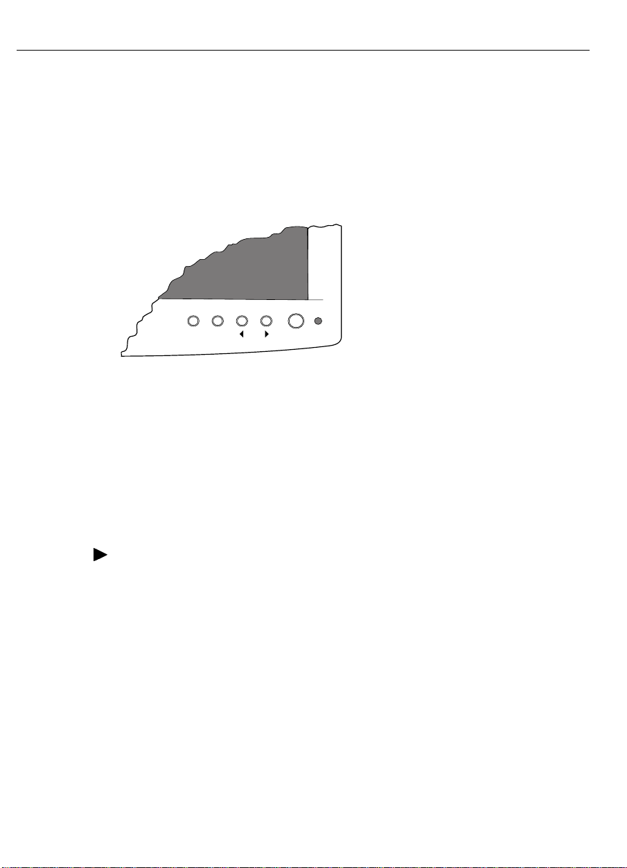
To turn on the Profile touch monitor, press the Power button on the
front of the display. In normal operat ion mode, t he Po wer status light
(LED) is steady green when the monitor is receiving power and a valid
video signal.
Menu Select Adjust Power
To po wer on the ChassisTouch monitor, plug in the power cable.
ChassisTouch does not have a power button or a powe r status light .
Testing the Touch Monitor
Be fore you test your touc h mo nitor, make sure all cables ar e
connected prop er ly. Be sure to tighten all cable scr ews.
¾
To test that the monitor is working properly:
1. Turn on your monitor, and then turn o n your computer.
2. Make sure the video image is centered within the screen area. Use
t he mon itor c on trols to ad just the image, if necessary.
You can adjust the horizontal and vertical position, image size,
co ntrast , and bright ne s s to better suit your video ca rd and your
personal preference. Refer to Chapter 3 for more information on using
the on-screen menu to adjust the video display.
Page 31
Chapter 2 Setting Up Your FPD T ouc h M onitor 31
Installing the Touchscreen Driver
TouchWare includes the software driver that lets your touchscreen
work with your computer. Yo u must be sure t o install the correct
touchscreen driver for your operating system. MicroTouch has
touchscreen drivers for the following PC operating systems:
• Windows 95 and Windows NT 4. 0
• Windows NT 3.51
• Windows 3.1x
• MS-DOS
• OS/2 System 3.x and 4.x
Th e proc edure for ins talling Tou chWar e fr om the CD is differe nt for
each operating system. Refer to the appropriate sect ion for your
operating system.
Note:
After you install TouchWare, be sure to restar t your computer
to load and activate the touchscreen driver.
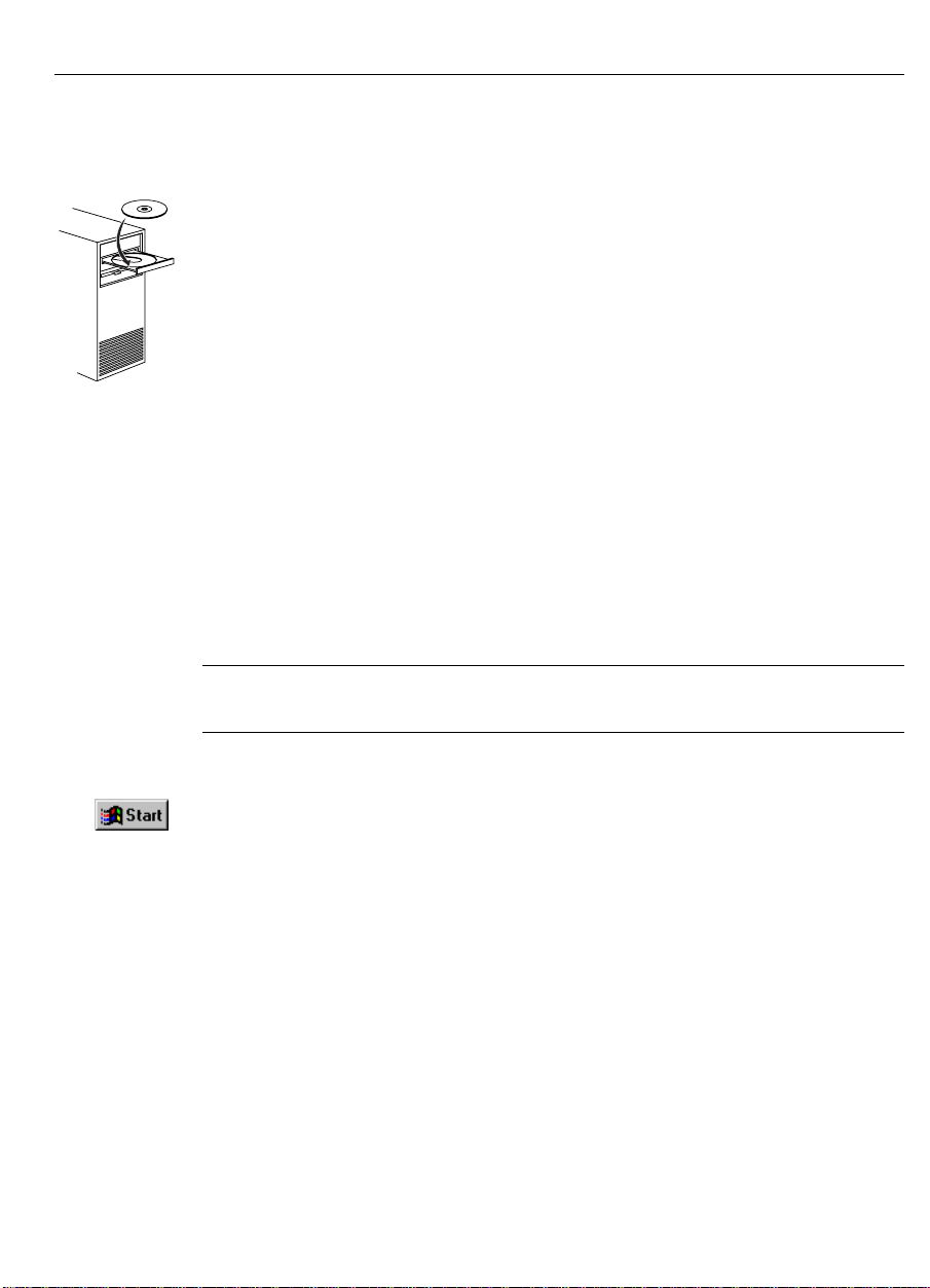
Installing TouchWare for Windows 95 or Windows NT 4.0
If the AutoStar t feature for your CD-ROM drive is active:
1. Insert t he TouchWare CD into the CD-ROM drive.
The system automatically detects the CD and runs the Setup
program.
2. Follow the on -s creen instr uc tion s to comple te the ins tallation.
After the software is installed, restart your computer to load and
activate the touchscreen driver. To co mplete the setup o f your
touch monitor, make sure you calibrate the touchscreen.
Page 32

32 FPD Touch Monitors Installation Guide
If the AutoSt ar t feature is not active:
1. Insert t he TouchWare CD into the CD-ROM drive.
2. Clic k on Sta rt Æ Settings Æ Contr ol Panel.
3. Dou ble-c lick on Ad d/Remove Programs.
4. Clic k on Install to ru n the \Setup pro gram on the CD.
5. Follow th e on-screen instr uc tions to co mple te the ins talla tion .
After the software is installed, restart your computer to load and
activate the touchscreen driver. To co mplete the setup o f your
touch monitor, make sure you calibrate the touchscreen.
Installing TouchWare for Windows 3.1x and MS-DOS
1. Insert the TouchWare CD into the CD-ROM drive.
2. Open t he Pr ogram Manager.
3. Open t he File menu and choose Run.
4. Enter D:\CDROM\SETUP
where D is the letter o f your CD-ROM drive.
5. Follow th e on-screen instr uc tions to co mple te the ins talla tion .
After the software is installed, restart your computer to load and
activate the touchscreen driver. To co mplete the setup o f your
touch monitor, make sure you calibrate the touchscreen.
Page 33
Chapter 2 Setting Up Your FPD T ouc h M onitor 33
Installing TouchWare for Windows NT 3.51
1. Insert t he TouchWare CD into the CD-ROM drive.
2. Open the Program Manager.
3. Open the File menu and choose Run.
4. Enter D:\SETUP
where D is the letter o f your CD-ROM drive.
5. Follow the on -s creen instr uc tion s to comple te the ins tallation.
After the software is installed, restart your computer to load and
activate the touchscreen driver. To co mplete the setup o f your
touch monitor, make sure you calibrate the touchscreen.
Installing TouchWare for MS-DOS Only
1. Boo t your system into MS-DO S .
2. Insert t he TouchWare CD into the CD-ROM drive.
3. Change to the CD-ROM drive.
For example, enter D: if you r CD-R OM is D rive D .
4. Enter INSTALL followed by the source drive, the destination
drive, and the destination directory.
For example, the following command copies the files from Drive D
(source) to Drive C (destination) and the \MTS\TOUCH directo r y:
INSTALL D: C:\MTS\TOUCH
5. Follow the on -s creen instr uc tion s to comple te the ins tallation.
After the software is installed, restart your computer to load and
activate the touchscreen driver. To co mplete the setup o f your
touch monitor, make sure you calibrate the touchscreen.
Page 34

34 FPD Touch Monitors Installation Guide
Installing TouchWare for OS/2
1. Insert t he TouchWare CD into the CD-ROM drive.
2. Open the OS/2 System Æ Comma nd Prompts Æ OS/2 window.
3. Enter D:\OS2\TW34\DISK1\SETUP
where D is the letter o f your CD-ROM drive.
4. Follow the on -s creen instr uc tion s to comple te the ins tallation.
After the software is installed, restart your computer to load and
activate the touchscreen driver. To co mplete the setup o f your
touch monitor, make sure you calibrate the touchscreen.
Page 35
Chapter 2 Setting Up Your FPD T ouc h M onitor 35
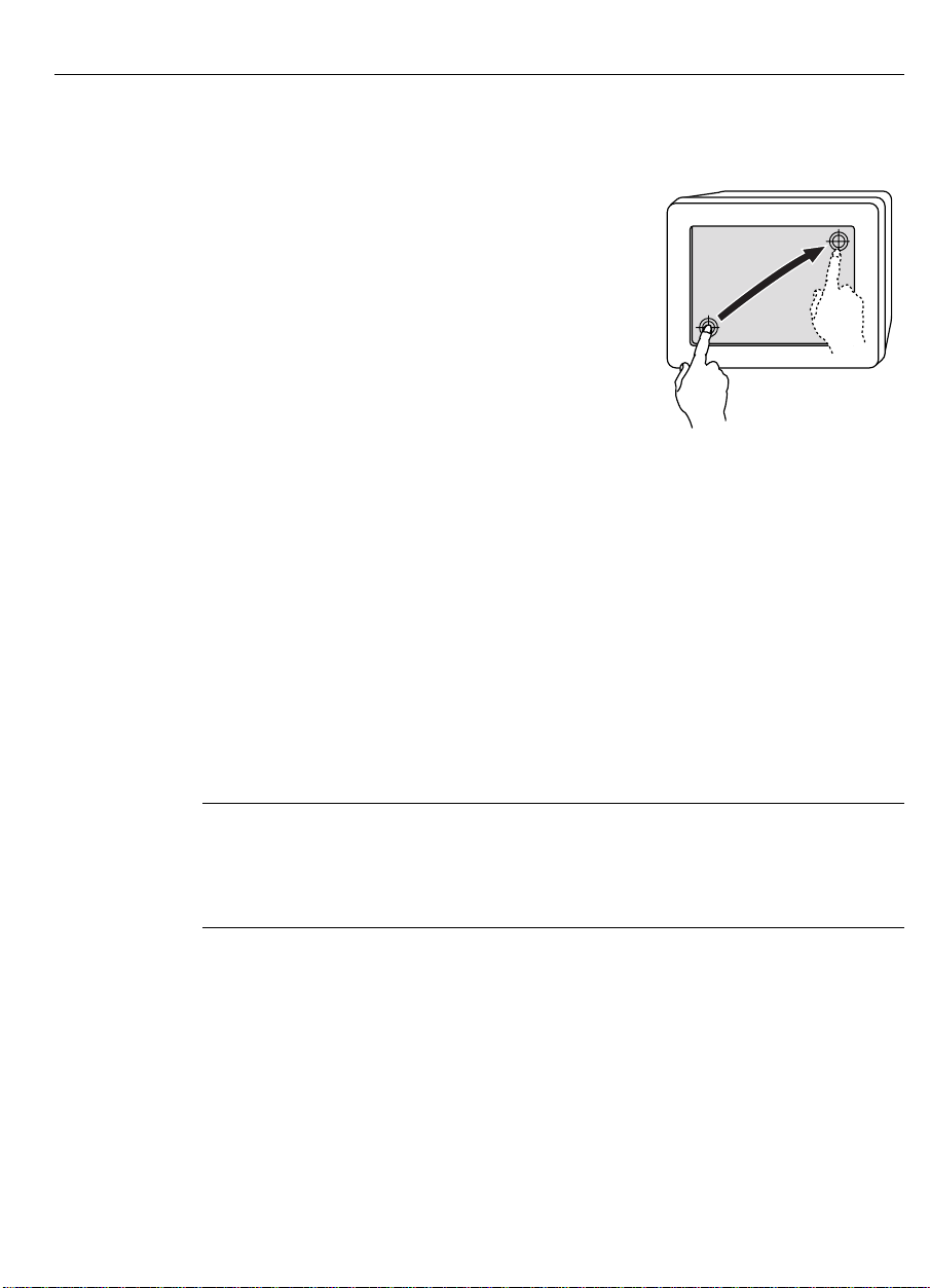
Calibrating the Touchscreen
After you connect your touch monitor
and install TouchWare, you must
calibrate the touchscreen. Calibration
serves two p u r p oses:
• Sets the act ive area of the
touchscreen
• Aligns t he t ouchscreen’s active area
to the underlying video
Calibration aligns t he act ive touch-sensitive area of the touchscreen
with the video image on the display. Calibration also determines the
edges of the screen’s image and locates the center of the touchscreen.
If the screen is not calibrated properly, the active area of the
touc hs c reen may not be aligned w ith the video or may be unnec e s sarily
sma ll in size.
To calibrate the touchscreen, o p en t he Touchscreen control panel and
select Calibrate. Follow the directions displayed on the screen. For
mo re information on calib ratio n, re fer t o the online h elp or the u ser
documentation for TouchWare.
Note:
Before calibrating the touchscreen, let the monitor warm up for
several minutes and then center the video image within the screen area.
Also, always calibrate the to uchscreen at the monitor video reso lution
t hat your touch app lica tion will u se.
Page 36

36 FPD Touch Monitors Installation Guide
Customizing the Touchscreen Settings
You can use the Touchscreen contr ol panel to set the following
preferences for the touchscreen:
• Define the touch actions that equat e to a mouse click,
double-click, and drag
• Define whether you hear a beep when you touch t he screen or
when you lift your finger off the screen
• Define how fast you must touch the screen to produce a
double-click
• Tune the to uchscreen cont r oller to the best oper ating frequency for
your current configuration
• Define whether to display the cursor and where the cursor appear s
relative to a touch (an offset)
In addition to calibrating and setting preferences, you can use the
control panel to view status information about the touchscreen and
access online help. For details on the control panel, refer to t he o nline
help or the user documentation for TouchWare.
Page 37

CHAPTER 3
Adjusting the Video Display
Yo ur FP D touc h monitor ha s s evera l control but tons, an on-screen
menu, an d a Monitor Ad justment pr ogr am for ad jus tin g the video
display. For example:
• You can adjust the pixel clock and phase to eliminate n oise.
• You can adjust the image contrast and brightness to your
ligh tin g c ondition s.
• You can adjust the horizontal and vertical position of the image.
This chapter presents guidelines for adjusting the video display and
describes how to use the available monitor cont r ols to adjust the image
t o your liking.
Page 38

38 FPD Touch Monitors Installation Guide
Guidelines for Adjusting the Display
Before You Make Any Adjustments
• Be su re to se t th e c on trols unde r your no rmal lighting conditions .
• Wait for the mon itor to war m up for 3 0 minutes be fore ad justin g
t he v ide o displa y. Most monitors will r equire at le ast 30 minutes
to war m up, st abilize completely, and reach their optimal operating
point. Some image characteristics, such as image cent er ing and
black -leve l, will va ry until the monitor warms up.
• Display a test image or pattern whenever you adjust the video.
Th e Monit or Adju stmen t progra m pro vides on e p attern for c lock,
phase, and position adjustments, and another pattern for contr ast
and br ightnes s adjustment s .
Using the Standard Controls for the Video Card
In addition to the standard controls on the monitor, each video card
has several controls that let you ad just the display settings. The
software and driver for each video card is unique. In most cases, you
adjust these setting s by usin g a progra m or utility provide d by th e
manufacturer o f the video card.
For example, you can use the Windows Display Properties contr ol
panel to adjust the deskto p ar ea ( r esolution), color dept h, and refresh
rate. Whenever you change these settings, the image size, position, or
shape may change. This behavior is normal. You can readjust the
image using th e monitor controls describe d in this cha pte r.
For more info rmat ion o n adjusting the de sktop area (r esolution), color
depth, or r efresh rate, r efer to the user manual that came with your
video card.
Page 39
Chapter 3 Adjusting the Video Display 39
MenuSelectAdjust
Controls for Adjusting the Video Display
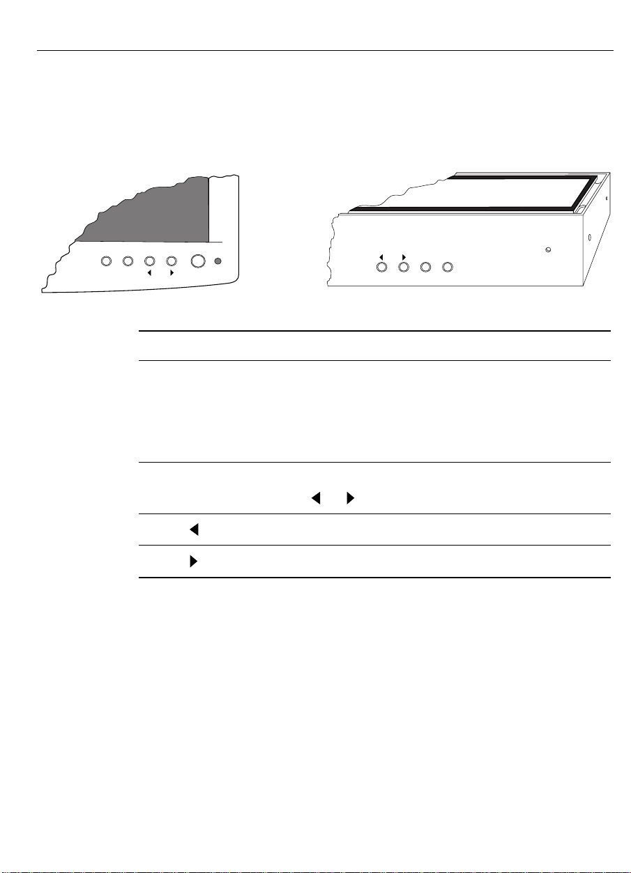
Your FPD touch monitor has four controls for adjusting the video
display.
Menu Select Adjust Power
Control Button Description
Menu Displays a menu of on-screen adjustment controls.
Pressing the Menu button again displays the
second set of menu opt ions. P r essing Menu again
hides the on-screen adjustment contr ols.
Select Selects the next item in the current menu.
Press or to change the value.
Adjust Decreases the value of the selected menu option.
Adjust Increases the value of the selected menu option.
If you do not press the Menu, Select, or Adjust buttons for
approximately 20 secon ds, th e Mon itor Adju stment program time s out
and hides the menu options. You can press the Menu button at any
time to display the options again.
Page 40
40 FPD Touch Monitors Installation Guide
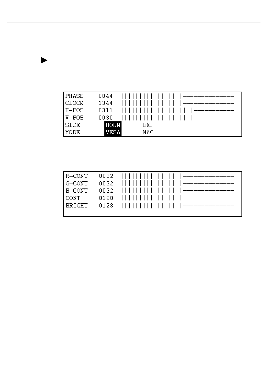
Displaying the Menu Options
¾
To displa y the menu for ad jus tin g the screen display:
1. Press the Menu but ton. T he system displays the first set of menu
options:
2. Press the Menu button again. The system displays the second set
of menu options:
3. Press the Menu button again to hide the menu .
Resetting Default Video Values
To reset the default values:
1. Turn off the monitor.
2. Press and hold the Menu button and the Select butt on while you
turn on the monitor.
Page 41

Chapter 3 Adjusting the Video Display 41
Overview of the Menu Options
Table 4 describes the options for adjusting the screen display.
Table 4. O ptions for A djusting the Sc r een Display
Menu Option Function Description
PHASE Clock Phase Synchronizes the relative phase of the pixel sampling
clock to the incoming video signal.
CLOCK Clock Frequency Adjusts the frequency of the pixel sampling clock. It is
important that this frequency closely match the original
pixel clock generating the analog video signal.
H-POS Horizontal Position Adjusts the horizontal position of the screen image.
Press
the image to the right.
V-POS Vertical Position Adjusts the vertical position of the screen image.
Press
image up.
to move the image to the left; press to move
to move the image down; press to move the
SIZE Display Size Switching Selects either normal size or expanded size. Expanded
size is for viewing either an 800 x 600 resolution or
a 640 x 480 resolution mapped to the full screen.
MODE VESA/MAC Selects either VE SA or Macintosh displa y.
R-CONT
G-CONT
B-CONT
CONT Contra st Adjusts th e cont rast between foreground and
BRIGHT Brightness Adjusts the background brightness. Specifically,
White Balance Adjusts the white balance of an image by adjusting the
red, green, and blue signal individually. The controls
adjust red intensity, green intensity, an d blue intensity
respectively.
background. Specifically, contrast adjusts the white
level of the monitor. Press
lighter; press
brightness adjusts the black level of the monitor.
Press
make it lighter. Try to adjust the brightness to match
the brightness level in the room.
to make the background darker; press to
to make it darker.
to make the image
Page 42

42 FPD Touch Monitors Installation Guide
Using the Monitor Adjustment Program
Th e M on itor Adju stment prog ram he lps you a dju st the display
settings. Use this program when setting up the display for the first
time or when changing the system settings.
You need to adjust the unit only once to the video card you are using.
Running t he Monitor Adjustment Program in Windows
¾
To run the Mon itor Adju stmen t program in Win dows:
1. Insert the LCD Monitor Disk into the diskette drive.
2. Run the appropriate program for your Windows operating system:
• For Windows 95 or Windows NT, run
\WIN\W95LCDADJ.EXE.
• For Windows 3.1x, run \WIN\W31LCDADJ.EXE.
3. Start the prog r am by pressing the spacebar. You can also click the
left mouse button to start the program.
4. Follow the on-screen instructions to adjust the monitor settings.
5. Contin ue to mak e a dju stments until the best v ide o image is
achieved.
Running t he Monitor Adjustment Program in MS-DOS
¾
To run the Mon itor Adju stmen t program in MS-DOS:
1. Insert the LCD Monitor Disk into the diskette drive.
2. Run \DOS\DLCDADJ.EXE.
3. Re fer to th e followin g section s for more info rma tion on ad justin g
the video display.
Page 43
Chapter 3 Adjusting the Video Display 43
Exiting from the Monitor Adjustment Program
¾
To exit from t he Monitor A djustment p rog ram:
• For Windows, click the right mouse button or pr ess the Esc key.
• For MS- DO S , p ress any key.
Adjusting the Clock and Phase Values
The Clock value defines the frequency of the pixel sampling clock. It
is impo rtant that this freque n cy c losely match the origina l pixel clock
generating the analog video signal.
The Phase value synchro nizes the relative phase of the pixel sampling
clock to the incoming video signal.
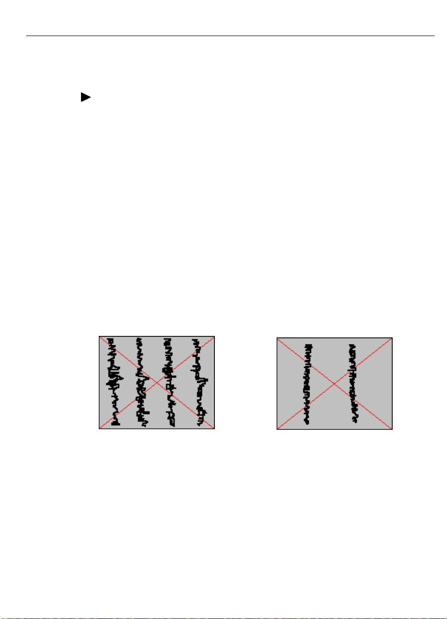
If the Clock or Phase value is incorrect , the screen image may display
one or more vertical bars (noise). The screen image may also flicker
or seem out of focus.
Because both the Clock value and the Phase value can affect the noise
level, the basic ru le for eliminating noise is as follows:
• First, adjust the C lock value until th e nois e is uniform a cross t he
entire scree n. (Yo u ma y not be able to elimin ate the n oise by
adjusting only the Clock setting.)
• Th en, adjust th e Pha se setting to eliminate th e nois e. T he Phase
value synchronizes the clock to the incoming video signal.
Page 44
44 FPD Touch Monitors Installation Guide
Note:
If the video out put of your computer is the same as the video
t iming spec ified in Table 2, th e or iginal Clock setting usua lly works
well. Therefore, you may only need to adjust t he Phase setting to
eliminate no ise.
¾
To adjust t he Clock and Phase values:
1. Run the Mon itor Adju stment prog ram an d display th e te st image .
2. Press Menu to display the first menu.
3. Pre ss Se lec t until you highlig ht the CLOCK setting .
4. Press Adjust to decrease the value; press Adju st t o increase
the value.
When a dju sting the Clock valu e, you will see vertic al bands of
noise or distort ion on the screen. E xamine the noise level and
adjust the Clock v alu e u ntil the no ise or d istor tion is uniform
across t he entire screen.
5. Pre ss Se lec t until you highlig ht the PHAS E settin g.
6. Press Adjust to decrease the value; press Adju st t o increase
t he v alu e. Continue to adjust the P hase settin g until you eliminate
the noise.
Page 45

Adjusting the Image Position
¾
To adjust t he horizontal or vertical position of the image:
1. Run the Mon itor Adju stment prog ram an d display th e te st image .
2. Press Menu to display the first menu.
3. Press Select until you highlight the H-POS setting.
4. Press Adjust to mov e the image to th e left; pre ss A dju st to
move the image to the right.
5. Press Select until you highlight the V-POS setting.
6. Press Adjust to mov e the image dow n; p ress Ad jus t to move
the image up.
7. Adjust the position until you center the image within the viewing
area.
Chapter 3 Adjusting the Video Display 45
Page 46

46 FPD Touch Monitors Installation Guide
Adjusting the Brightness and Contrast Values
The B right ne s s setting det ermines the black leve l of the monitor.
• If you s et the va lu e too high or too bright , t he monitor c annot
produce black. The result is a washed out image.
• If you set the brightness value too low, the monitor produces the
dimmer grays as bla ck . The r esult is an image w ith very low
contr ast.
Adjust t he s creen brightness for the typical brightnes s leve l in t he
roo m. Also, look near the edges of the screen. The edge is the best
place to determine if the background is actually black or merely gray.
Once you set the Brightness, the Contrast setting determines the white
level of the screen image. It defines the contrast between foreground
and background (the range between the lightest tones and the darkest
t on es in an imag e) . The optimum w hite level dep ends on room
lighting. Try to set the Contrast to the highest intensity that is
comfortable to you.
¾
To adjus t the cont rast and bright ness value s :
1. Run the Mon itor Adju stment prog ram an d display th e te st image .
2. Press Menu twice to display the second menu.
3. Pre ss Se lec t until you highlig ht the BRIGHT s etting.
4. Press Adjust to make the image blacker; press Adjust to make
t he image w hiter.
5. Pre ss Se lec t until you highlig ht the CO NT setting .
6. Press Adjust to decrease contrast ( make the image lighter); press
Adjust to increase contr ast (make the image darker).
Page 47

Adjusting the White Balance
You can also adjust the white balance of an image by adjusting the red,
green, and blue signal individually. Use the R-CONT, G-CONT, and
B-CON T settin gs to ad jus t red in tensity, green in tensity, and blue
intensity re sp ec tively.
You can adjust the color o f white that results from equal combinat ions
of the red, green, and blue primary colors. This color white is often
referred to as a neutral white.
Th e c olor w h ite c an vary from a warm wh ite with a mild pinkish t int
(more red th an b lue ) to a cool white with a mild bluish tint (more blue
than red). The co nt r ol works by adjusting the relative strengths of the
red, green, and blue primary colors.
Chapter 3 Adjusting the Video Display 47
Page 48

48 FPD Touch Monitors Installation Guide
Expanding the Image Size
The native or intended resolution for the MicroTouch 13.8" and 15.0"
flat-panel monitor is 1024 x 768.
If you w ant to use a lower resolu tion , the monitor w ill show t he imag e
using only the tot al number of pixels generated by the source. For
example, the monitor uses only 800 pixels across and 600 lines of
pixels down the screen when displaying an SVGA (800 x 600)
resolution. The remaining pixels are not used. I n t his case, the
monitor pr eser ves t he image quality, but does no t use the entire
sc reen . You will see a high-q ua lity imag e center ed in the display an d
surrounded by a black border of unused pixels.
You can use the monitor’s on-screen contr ols to expand the image to
fill t he entire screen. To fill a 1024 x 768 flat-panel, the monitor
expands an 800 x 600 resolution by 1.25 and a 640 x 480 resolution
by 1.6. In both cases, the monitor spreads fewer pixels of information
across a larger number of pixels. Although this technique produces an
image th at fills the entire screen , the ima ge will be distor ted . The
pixels will ta ke on a b roa der or fuzz ier ap pe ar ance.
¾
To expan d the image size to fill the screen :
1. Press Menu to display the first menu.
2. Pre ss Se lec t until you highlig ht the SIZE s etting.
3. Press Adjust to select EXP ( for expanded image).
Page 49

CHAPTER 4
Guidelines for Integrating
Your FPD Touch Monitor
This chapter describes the options for integrating the ChassisTouch
and Prof ile monitors in to your touc h app lication.
• The ChassisTouch monitor is designed specifically for indoor
kiosks, ATMs, and industr ial enclosures. All ChassisTouch
monitors are encased in rugged metal instead of plastic, making
them easy to integrate into your kiosk.
• The Profile monitor , which features a sleek design and a small
footprint, is ideal for the desktop or counter top. You can also
mo unt th e P rofile monitor to a w all.
Page 50
50 FPD Touch Monitors Installation Guide
Mounting the ChassisTouch Monitor
You can mount the ChassisTouch monitor in a number of different
ways.
ChassisTouch Hardware Accessory Kit
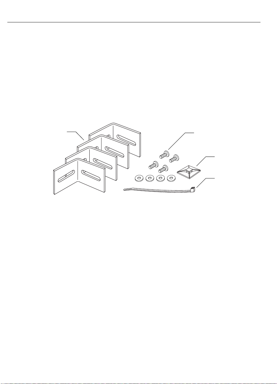
The ChassisTouch monitor includes a hardware accessory kit for
mounting the unit into a kiosk, ATM, or industrial enclosure.
Four brackets
Four 8-32 x 3/8" screws
and four #8 flat washers
Cable mount
Cable tie
Page 51
Chapter 4 Guidelines for Integrati ng Y our FPD Touch Moni tor 51
Mounting Options
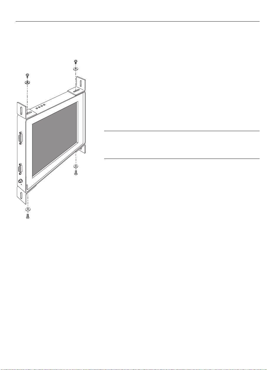
The ChassisTouch hardware accessory kit includes
four brackets, washers, and screws. T he mounting
holes are located on the sides of the monitor and are
threaded to an 8-32 thread.
You attach the brackets t o any of the four edges of
the chassis. The brackets are slott ed, allowing the
chassis to slide in and out. You can also rotate the
brackets to various positions.
Note:
Do not mount the chassis unit directly from
the rear o f the cover. Always use the brackets
provided.
ChassisTouch Cable Connectors
The cable connectors on t he ChassisTouch monitor
may be mounted either on the side or on the bottom of
the unit, depending on the model you have.
Access to the Video Controls
The contro ls (four butt ons) for adjusting the video display are always
located at the top of the ChassisTouch monitor. T hese four but tons let
you display the on-screen menu and adjust the phase, clock, image
pos ition, contra st, and brig htne ss. M ak e sure you w ill be able to
access the video contro ls once the ChassisTouch monitor is installed.
Page 52
52 FPD Touch Monitors Installation Guide
Clearance and Ventilation
• Leave at least two inches of space behind the ChassisTouch
monitor for p ro per ventilation.
• Keep all ventilation slots and op enings clean. Vacuum the opening
if you notice dirt accumulating on them.
• Do not block ventilation slots and openings with objects or install
the display in a place where ventilation may be hindered. Always
maintain adeq ua te ventilatio n to prote ct the display from
overheating and to ensure reliable and continued operation.
Securing and Routing System Cables
You must be sure to secure all cable connections. Shaking and
vibration, es pe cially during shipmen t, may dislodge comp on ents tha t
are improperly connected.
• Be sure to tighten all cable screws.
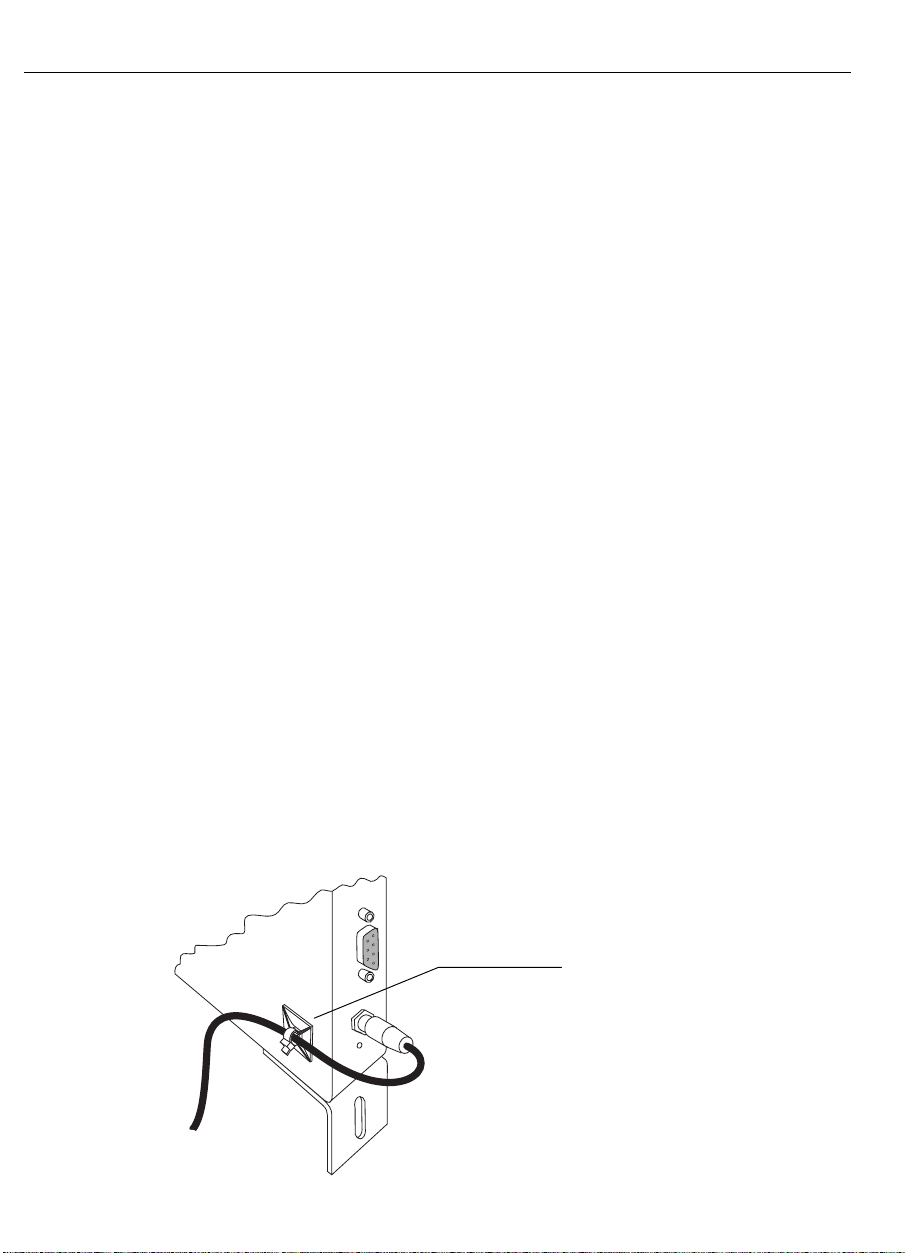
• Use the cable tie and cable mount supplied in the ChassisTouch
hardware kit to secure t he power supply cable.
• Route all wiring and cabling away from heat sources and sharp
metal edges to avoid damage. Also, keep the to uchscreen cable
away from sources of electromagnetic and radio frequency
interference.
Use the cable tie and
mount to secure the
power cable
Page 53
Chapter 4 Guidelines for Integrati ng Y our FPD Touch Moni tor 53
Mounting the Profile Monitor to a Wall
To mount the Profile monitor to a wa ll, you ne ed the following
supplies:
• Two mounting fixtures (screws or nails). The fixt ur e head must fit
into the two notches on the back of the monitor. Additionally, the
fixture must support t he weight of your monitor and the hanging
cables.
• Tools: Phillips-hea d s cr ew driver, hamme r, a n d drill.
¾
To mount the Profile monitor to a wa ll:
1. Place the monitor face down on a scratch-resistant surface.
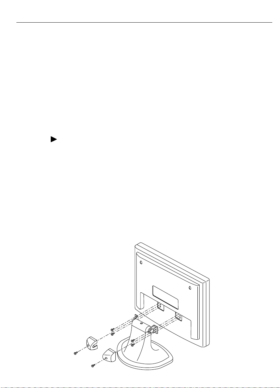
2. Remove the base from the monitor .
• Remove the two screws from the covers. Remove the two
covers.
• Remove the four screws holding the base to the monitor. The
base and the monitor will separate.
• Sto r e the two covers, screws, and base in a safe location in
case you want to use them in the future.
Page 54
54 FPD Touch Monitors Installation Guide
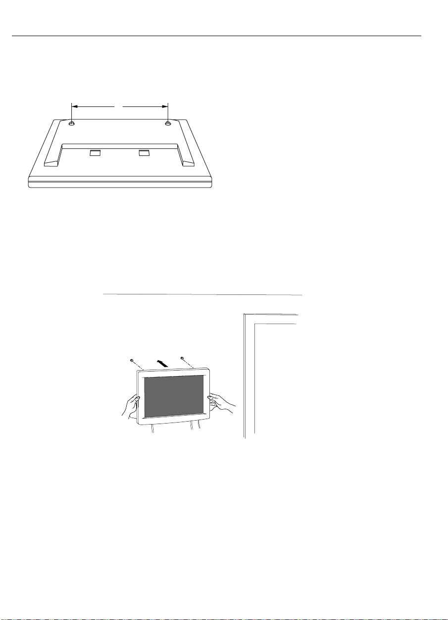
3. Check the measurement between the two no tches on the back of
the monitor.
A
Monitor Size Measurement
13.8" A = 10" (255 mm)
15.0" A = 11" (280 mm)
4. Place two pencil marks on the wall indicating the location of the
mounting fixt ur es.
5. In stall the mounting fixtures into the wall.
6. Hang the monitor on t he wall by aligning the two no tches on the
rear of the monitor to the fixtures on the wall.
Page 55

CHAPTER 5
Maintenance and Troubleshooting
If you have a problem setting up or using your monitor, you may be
able to solv e it you rs elf. Befor e c alling Micr oTouch , try the suggest ed
actions that are appro p r iate t o the problems you are experiencing with
the monitor.
You may also want to co nsult your video card user’s manual for
additional troubleshooting advice.
Page 56

56 FPD Touch Monitors Installation Guide
Maintaining Your Touch Monitor
To maintain your display and keep your monitor o per ating at peak
performance:
• Keep your monitor and screen clean. Refer to “Touchscreen Care
and C leaning ” later in this chap ter fo r more in format ion o n
cleaning the t ouchscreen.
• Adjust the monitor video controls. Refer to Chapter 3 for more
information.
• Keep all ventilation slots and op enings clean. Vacuum the opening
if you notice dirt accumulating on them.
• Do not block ventilation slots and openings with objects or install
the display in a place where ventilation may be hindered. Always
maintain adeq ua te ventilatio n to prote ct the display from
overheating and to ensure reliable and continued operation.
Touchscreen Care and Cleaning
The touchscreen requires very little maintenance.
MicroTouch recommends that you periodically clean the glass
touchscreen surface.
• Use isopropyl alcohol or a non-abrasive glass cleaner. Avoid using
cleaners other than glass cleaners. Do not use any vinegar- based
solutions.
• Apply the cleaner with a soft, lint-free cloth. Avoid using gritt y
cloths.
• Always dampen the cloth and then clean the screen. Be sure to
spray the cleaning liquid onto the cloth, not the screen, so that the
drippings do not seep inside the display or stain the bezel.
• Always handle the touchscreen with care. Do not pull on or stress
cables.
Page 57

Chapter 5 Maint enanc e and Troubleshooting 57
Monitor Installation Problems
Problem Possible Causes and Solutions
No image d isp laye d
(blank screen)
Is the monitor receiving power?
• Check that the computer’s power cable is connected
properly and securely int o a grounded electrical outlet.
• Check that the AC/DC power supply is firmly plugged into
the monitor. Check that the monitor’s power cable is
connected proper ly and securely to an electrical outlet.
• Check that the power butto n and status light are on (Pr ofile
touc h monitor only).
• Try using another power cable.
• Try using another electrical outlet.
Is the monitor receiving a valid video signal from the PC?
• Check that the computer is powered o n.
• Check that the video cable is connected properly and
securely to the monitor and the computer.
• Check that no pins are bent in the video cable connector.
• Check that the video card is fir mly seated in the card slot in
your computer.
• Check that the video input from the video card falls within
t he timing ran ge of the display. Refer to Table 2 for details.
• Check that your computer is using a supported display
mode. Refer to Table 2 for details.
Is the monitor is in Power Management mode? Touch the
screen, press any key on the keyboard, or move the mouse to
resto re operation.
Are the brightness and contrast settings too low? Use the
monitor controls to adjust these values.
Page 58

58 FPD Touch Monitors Installation Guide
Problem Possible Causes and Solutions
Abnormal image Check the following items:
• Check that the video input from the video card falls within
t he timing ran ge of the display. Refer to Table 2 for details.
• Check that the video cable is connected properly and
securely to the monitor and the computer.
Colors of image
are abnormal
Disturbances on
the screen
Check the following items:
• Check that the video cable is connected properly and
securely to the monitor and the computer.
• Check that no pins are bent in the video cable connector.
The video display adjustments are incorrect.
Refer to Chapter 3 for adjusting procedures.
Page 59

Chapter 5 Maint enanc e and Troubleshooting 59
Troubleshooting the Touchscreen
If you are experiencing problems with the to uchscreen, check the
fo llowing list of co mmon installation errors .
Table 5. Common Touchscreen Installation Errors
Common Installation Errors Possible Solutions
Touchscreen does not respond
to touch
• Review the installation procedures. Are all
cables connected pro per ly?
• After you installed TouchWare, did you restart
your PC to activate the touchscreen driver?
• Are the communication settings correct? Is the
touchscreen tr ying to use the same COM port
or IRQ as another device (for example, a
mouse)? If so, a hardware device conflict will
result a n d the touchscre en will not work.
Touchscreen is not accurate Calibrate t he touchscreen for the current video
resolution and operating system.
Cu rs or do es n ot follow fing er
movement or does not reach
Calibrate the to uchscreen for the current video
resolution and operating system.
the edges of the screen
Cursor is not located directly
underneath your finger
• Open the Touchscreen contro l panel and make
sure all cursor o ffsets (vertical, edge/horizontal)
are turned off.
• Calibrate the to uchscreen for the current video
resolution and operating system.
Cursor is extremely jittery or
erratic
Stabilize the cursor by adjusting the operating
frequency of the touchscreen contro ller.
Cursor lags finger Lower the baud of the to uchscreen contr oller and
the to uchscreen driver.
Page 60

60 FPD Touch Monitors Installation Guide
Power Status Light
Th e Profile touch monitor has a powe r s tatus light (LE D) on the front
of the display. You can use the status light to help you determine
possible problems with your monitor.
Table 6. Status Light on the P r ofile Desktop Monitor
Status Light Description
Off The monitor is not receiving any power.
Green light Normal operation. Indicates the cables are properly
connected, the monitor is receiving power , and the
monitor is receiving a valid video signal.
If the status light is green, but t he screen is blank,
check the following items:
• The brightness and co ntr ast may be to o low. U s e
the monitor controls to adjust.
• The display mode of the computer is outside the
range of the monitor. Reconfigure your computer
to use a suppor ted display mode. Refer to Table 2
fo r d etails.
Orange light Indicates the monitor is receiving power, but the
screen is blank.
• Th e monitor ma y b e in Pow er Mana ge ment mode.
Touch the screen, press any key on the keyboard,
or move the mouse to restore the monitor to
normal operation.
• The monitor is not r eceiving a valid video signal
from the PC. Check that the computer is powered
on, check that the video cable is firmly connected
to the monitor and the co mputer, and check that
no pins are bent in the video cable connector.
Page 61

Power Management
The Profile and ChassisTouch monitors co nform to the Video
Electronics Standards Association (VESA) Display Power
Management Signaling (DPMS) standard.
To benefit fr om power manage ment, the monitor must be used in
conjunction with a computer and video card that implements the
VESA DPMS standard.
The PC automatically invokes t he po wer management feature if you
do not use the touchscreen, mouse, o r keyboard for a user - defined
per iod of time. To restore the video image, simply touch the s cr ee n,
press a key, or move the mouse.
Chapter 5 Maint enanc e and Troubleshooting 61
Page 62
62 FPD Touch Monitors Installation Guide
Video Input Pin Assignment
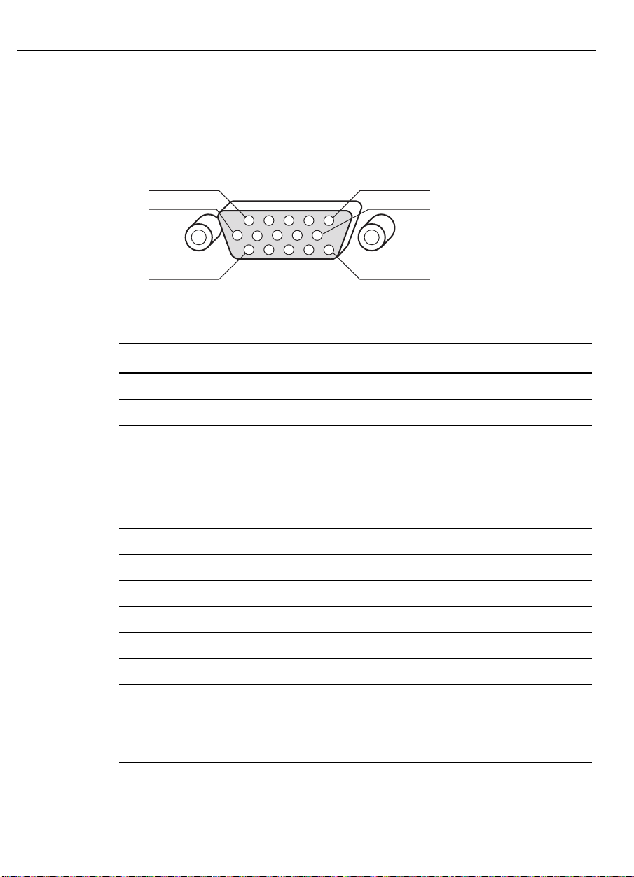
Table 7 describes the pin assignment of the video co nnector on the
flat-panel display. The connector is a 15-pin mini D-sub connector.
5
10
15
Table 7. Video Input Pin Assignment
Pin Number Signal Connector
1 Red video signal
2 Green video signal
3 Blue video signal
4 Ground
5 No connection
6 Ground for red video signal
7 Ground for green video signal
8 Ground for blue video signal
9 No connection
1
6
11
10 Ground
11 Ground
12 No connection
13 Horizontal sync signal
14 Vertical sync signal
15 No connection
Input signals are RS- 342 compatible with the video level up to 0.7 V
point-to - p oint @ 75 ohms impedance. The sync signals are TTL
negative with sep a rate sync signals for hor izontal and ve rt ica l.
Page 63

Approvals
APPENDIX A
Compliance Statements and
Monitor Specifications
Table 8 lists the appro vals received for the 13.8" and 15.0" Profile and
ChassisTouch FPD to uc h monitors.
Table 8. Appr oval s
Approval Profile Monitor ChassisTouch Monitor
CE / CISP R 2 2-B
(EN55022)
CSA
cUL/UL1950 —
C-TICK
FCC Class B
TÜV/GS
UL1950
VCCI Class B
✓✓
✓
✓✓
✓✓
✓✓
✓
✓✓
—
✓
—
Page 64

64 FPD Touch Monitors Installation Guide
Federal Communications Commission (FCC) Statement
Th is equipment has b een tested an d fou nd to comply with the limits for
a Class B digital device, pur suant to Part 15 of the FCC Rules. These
limit s are de sig n ed to pro vide r easonable pro tection ag ainst ha rmfu l
interference when the equipment is operated in a residential
environment. This equipment generates, uses, and can radiate radio
frequency energy and, if not installed and used in accordance with the
instruction manual, may cause harmful int er ference to radio
communications. However, there is no guarantee that interference will
not occur in a particular installation. If this equipment does cause
harmful interference to radio or television reception, which can be
determined by turning the equipment off and on, the user is
encouraged to try to co r r ect the interference by one or more of the
following measures:
• Reorient or r elocat e the receiving antenna.
• Increase the separation between the equipment and receiver.
• Connect the equipment into an outlet o n a circuit different from
that t o which the receiver is connected.
• Consult the dealer for help.
Proper ly shielded and grounded cables and connectors must be used in
o rder to me et FCC emission limits. Pr ope r cab les and conne ctor s a re
available from MicroTouch author ized dealers. MicroTo uch is not
responsible for any radio or t elevision interference caused by using
other than recommended cables and connectors o r by unauthorized
changes or modifications to t his equipment. Unauthorized changes or
modifications could void the user’s authority to operat e the equipment.
Th is d evice comp lies with Part 15 of the F CC Rules . Oper ation is
subject to the following two conditions: (1) this device may not cause
harmful interference, and (2) this device must accept any interference
received, including inter ference that may cause undesired operation.
Page 65
Appendix A Compli anc e S tatement s and Monitor Speci fications 65
Industry Canada Compliance Statement
This Class B digital apparatus meets all requirements of the Canadian
Interference-Causing Equipment Regulations.
Cet appareil numérique de la Classe B respecte toutes les exigences
du Règlement sur le matériel brouilleur du Canada.
VCCI Class B ITE Statement
This is a Class B product based o n t he st andard of the Voluntary
Control Council for Interference from Information Technology
Equipment (VCCI). I f this is used near a radio or television receiver in
a domestic envir onment, it may cause r adio interference. Install and
use the equipment according to t he instructional manual.
Page 66

66 FPD Touch Monitors Installation Guide
Specifications for the 13.8" and 15.0" FPD Touch Monitors
Table 9. Spec ifications for 13.8" and 15.0" FPD Touch Moni tors
Specificat ion 13.8" FPD 15.0" FPD
LCD Panel Type 13.8" (diagon al) TFT 15.0" (diagonal) TFT
Physical Dimensions
(Width x Height x Depth)
Weight Desktop LCD Module Only
Display Type TFT Color LCD TFT Color LCD
Active Display Area
(Horizontal x Vertical)
Pixel Dimension
(Horizontal x Vertical)
Desktop
13.9" x 12.9" x 6.5"
(353 x 327 x 166 mm)
Chassis
13.2" x 9.74" x 1.9"
(335 x 247 x 48 mm)
8.9 lbs. (4.0 kg)
Chassis
6.0 lbs. (2.7 kg)
Desktop
11" x 8.27"
(279.6 x 209.7 mm)
Chassis
11.3" x 8.4"
(287 x 213 mm)
0.273 x 0.273 mm 0.297 x 0.297 mm
Desktop
15.2" x 13.9" x 6.5"
(385 x 353 x 166 mm)
Chassis
14.2" x 10.6" x 1.9"
(361 x 269 x 48 mm)
Desktop LCD Module Only
10 lbs. (4.5 kg)
Chassis
7.5 lbs. (3.4 kg)
Desktop
12" x 9"
(304.1 x 228.1 mm)
Chassis
12.1" x 9.2"
(307 x 234 mm)
Viewing Angle Horizontal: ±70° maximum
Vertical: ±55° maximum
Display Colors 262, 144 colors maximum (18 bit)
Display Resolution For optimal viewing: 1024 x 768 (XGA)
For monitor compatibility/setup: 800 x 600 (SVGA), 640 x 480 (VGA)
Brightness 150 candela per square meter (cd/m2)
Contrast Ratio 200 : 1
Tilt Desktop: +30°, -5°; Chassis: not applicable
Horizontal: ±70° maximum
Vertical: ±60° maximum
Page 67

Appendix A Compli anc e S tatement s and Monitor Speci fications 67
Specificat ion 13.8" FPD 15.0" FPD
Response Time 30 ms
Temperature Operation: 0° to +40° C, Ambient
Storage: -25° to +60° C, Ambient
Humidity 90% @ 35° C
Power Supply
(AC/DC Adapter)
Power Management VE SA DPMS compatible
Power Consumption < 17 W, normal operation
Input Signal Video: Analog 0.7 V point-to-point, 75 ohms positive
V-Sync Frequenci es
Supported
Connectors 2-pin DC power connector (12VDC)
Accessories Power supply (12VDC) and power cable
On-screen Displa y (OSD)
Monitor Controls
Input: AC 100 – 240V, 50 – 60 Hz
Output: +12 VDC, 2.0A
Normal mode: 21 Watt maximum (excludes AC/DC adapter)
Standby/suspend/off modes: 3 Watt maximum
Sync: TTL level, positive/negative, separate sync
70 Hz, 60 Hz
15-pin mini D-Sub high density female VGA video connector
9-pin D-type female RS-232 touchscreen output
VGA video cable
RS-232 serial touchscreen cable
ChassisTouch: mounti ng brackets, screws, and washers (4 of each);
cable tie an d cable mount
Phase, Clock, Horizontal Position, Vertical Position, Size, Mode,
Contrast, Brightness, R-Contrast, G-Contrast, B-Contrast
Manua l C on trol Buttons Desktop: Menu , Select, Adjust ( and ), Power
Chassi s: Menu, Select, Ad just (
Approvals Desktop
CE / CISPR 22-B (EN55022), CSA, C-TICK,
FCC Class B, TÜV/GS, UL1950, VCCI Class B
Chassis
CE / CISPR 22-B (EN55022), cUL/UL1950, C-TICK,
FCC Class B, TÜV/GS, VCCI Class B
and )
Page 68

68 FPD Touch Monitors Installation Guide
Specificat ion 13.8" FPD 15.0" FPD
Warranty Monitor: one year
Touchscreen Components: five years
Touchscreen Technologies Supported: capacitive and 5-wire resistive
Controllers Supported: SMT3V and SMT3RV
Connection: RS-232 serial communication
Page 69

Index
A
AC/DC power supply 29
accessories and cables 24
accessory kit for ChassisTouch 50
active -ma trix technolog y 18
Adjust butt ons 39
adjusting the video display 39
AM-TFT LCD technology 18
B
balance, white 47
black border around image 19
brightness
adjusting the 46
definition of 41
bulletin bo ard s ystem (B B S) 1 3
but tons
Adjust 39
Menu 39
Power 30
Select 39
C
cable tie and mount 52
cables
connecting the monitor 28
list of monitor 2 4
calibrating the touchscreen 35
Canada compliance statement 65
card, video 25
ChassisTouch monitor
accessory kit 50
clearance 52
connecting the 28
features and benefits 17
mounting options 50
overview 16
vent ilation 52
cleaning the t ouchscreen 56
clearance, ChassisTouch 52
clock frequency
adjusting the 43
definition of 41
clock phase
adjusting the 44
definition of 41
Page 70

70 FPD Touch Monitors Installation Guide
color depth, defining 26
compliance statements 63
connecting the touch monitor 28
contr ast
adjusting the 46
definition of 41
contro l panel, Touchscreen 35
corpo r ate headquarters 14
customizing touchscreen sett ings 36
D
default video values, resetting 40
desktop area 26
display mode 26
Dis play Power M anag ement Signaling
(DPMS) 61
driver
installing a v ideo 25
installing the touc hscree n 31
E
H
hardware accessory kit 50
headquarters, co r porate 14
help
bulletin bo ard s ystem 13
phone support 12
world wide web 13
horizontal posit ion of
video image 41, 45
I
image position, adjusting 45
image size, expanding 48
Industry Canada compliance
statement 65
installation
precautions 8
safety precautions 8
troubleshooting 57
warnings 8
Internet address, MicroTouch 13
E-Mail address 13
expans ion ra te 2 6
F
FCC statement 64
features and benefits 17
fire hazard precautions 8
flat-panel display 16
FPD, definition of 15
frequency, clock
adjusting the 43
definition of 41
L
LCD technology 18
LED, power 60
light, power stat us 60
liquid cryst al display (LCD)
technology 18
M
maintainin g you r touch mon itor 56
maintenance of touchscreen 56
Menu button 39
Page 71

Index 71
menu options
displaying 40
overview of 41
MicroTouch Inter net addr ess 13
mode, display 26
mo nit or See touch monitor
Monitor Adjust ment p r ogram
exitin g fro m 43
running the 42
monitor cables, connecting the 28
N
noisy dis pla y imag e 4 3
O
on-screen menu options 40
P
phase, clock
adjusting the 44
definition of 41
phone support 12
pin assignment, video input 62
position of video image 41
Po wer button 30
power cable, connecting the 29
power indicator 60
power management 61
power supply
connecting the 29
securing the ChassisTouch 52
po wering on the touch monitor 30
precautions
installation 8
safety 8
service and repair 9
shock and fire hazard 8
preferences, touchscreen 36
Profile touc h mo nitor
connecting the 28
features and benefits 17
overview 16
wall moun t 53
R
rate, expa ns ion 26
refresh rate, adjusting the 26
regulatory statements 63
repair precautions 9
requirements, system 22
reset default video values 40
resolution
on a CRT 20
on a flat-panel display 18
RS-232 serial touchscreen cable,
connecting the 28
S
safety precautions 8
scan rate 26
Select butto n 39
serial touchscreen cable,
connecting the 28
service precautions 9
shock precautions 8
size of image 48
specifications 66
starting up the touch monitor 30
statements, co mpliance 63
Page 72

72 FPD Touch Monitors Installation Guide
status light, power 60
support, technical 12
system requirements 22
T
technical suppo r t 12
technology, AM-TFT LCD 18
telephone support 12
testing the touch monitor 30
TFT technology 18
t hin-film tr ansistor techn ology 18
touc h monitor
cables and accessories 24
connecting the 28
maintainin g the 56
specifications 66
testing the 30
turning on the 30
unpacking the 23
video resolution 18
touch settings 36
touchscreen
calibrating the 35
cleaning the 56
connecting the 28
custo mizing settings 36
installing the software dr iv er 31
touchscreen cable, connecting the 28
Touchscreen control panel 36
t ouc hscree n driver , in stalling th e 3 1
TouchWa re, installing 31
troubleshooting
touchscreen 59
video display 57
turning on the touch monitor 30
U
unpacking the touch monitor 23
V
VCCI Class B ITE statement 65
vent ilation r e quire ments 5 2
vertical position of video image 41, 45
vertical scan rate 26
VESA, definition of 61
video cable, connecting the 28
vid eo card, installing a 25
video cards, tested 27
video c onnec tor p in as s ignment 62
video c ontrol but tons 39
video display
adjusting the 39
resetting default values 40
vid eo driver, installing a 2 5
video image
adjusting position of the 45
expanding size of the 48
video input pin assignment 62
video resolution
defining the 26
on a CRT 20
on a flat-panel display 18
vid eo timing 26
W
warnings, installation 8
white balance, adjusting the 47
World Wide Web site 13
worldwide offices 14
Page 73

World Wide Web: http://www.microtouch.com E-Mail: [email protected] m
ACTURA KIOSKS
ONG KONG
H
F
USTRALIA
A
+852 2333 6138 • I
PAIN
S
+34 (9) 3415-6285 • T
, a division of MicroTouch Systems, Inc ., 716-424-4300, Fax 716-424-4335
+61 (03) 9561 7799 • F
Documen t Numb er: 19-225, V ersion 2.0
MicroTouch Systems, Inc.
Corporate Headquart e r s
NITED STATES
U
978-659- 9000, Fax 978-659-9100
MicroTouch W orldwide Offices
RANCE
TALY
+39 (0) 39-230-2230 • J
AIWAN
+886 (02) 2226-0875 • U
+33 (1) 45 13 90 30 • G
APAN
+81 (044) 811-1133 • K
NITED KINGDOM
ERMANY
+49 (0) 211-59907-0
+44 (0) 1235-444400
OREA
+82 (2) 552-3198
 Loading...