

Page 1
About ScanWizard 5
ScanWizard 5 is Microtek's scanning
software developped exclusively for
Microtek scanners. ScanWizard 5's
unique dual interface has features that
both the novice and experienced scanner
users will love.
ScanWizard 5's two interface are named
ScanWizard 5-Standard Control Panel
and the ScanWizard 5-Advanced Control
Panel.
Learn more about the Standard Control
Panel
Learn more about the Advanced Control
Panel
Switching Between Standard and
Advanced
Page 2
Quick Start-up
Scanning sequence is done in five easy steps.
Step 1. Install Microtek ScanWizard 5
Step 2. Position your original material
Step 3. Launch ScanWizard 5
Step 4. Scan your material
Step 5. Save your scan material
Step 6. Exit ScanWizard 5
Step 1. Install Microtek ScanWizard 5
Install the ScanWizard 5 scanner driver (included in your Microtek CDROM) as instructed in the Installing and Getting Started booklet
(a separate document that came with your scanner package).
For ScanWizard 5 to work properly after installation, the correct scanner
model should be properly connected to your host beforehand and it needs
to be "powered on" before launching the software.
Step 2. Position your original material
Place your material face down on the scanner bed.
Step 3. Launch ScanWizard 5
A. Launching ScanWizard 5 as a stand-alone program
Double-click the ScanWizard 5 icon on your desktop; or
B. Launching from an image-editing application
Windows: Go through the Windows menu - click Start, Programs,
Image-editing software.
Page 3
Macintosh: Launch your image-editing software from its folder.
Step 4. Scan your material
As soon as you launch ScanWizard 5, it will automatically detect, configure,
scan, and perform a fast preview of the scan material and displays it in the
preview area of the panel.
To set and make adjustments to the image, use the Tool buttons (Original,
Scan Type, Purpose, Scale Output, or Adjust).
Step 5. Save your scan material
You need to click the Scan to button if you wish to store the scanned
image(s) into a file and easily retrieve it for future use.
Click the Scan to button to save, print, or deliver your image(s) directly to
another application (web, E-mail, or OCR).
Step 6. Exit ScanWizard 5
Windows: To quit ScanWizard 5, simply click on the Exit button
located at the top right corner of the Standard Control Panel.
Macintosh: The Exit button is located at the top left corner of the
Standard Control Panel.
Page 4
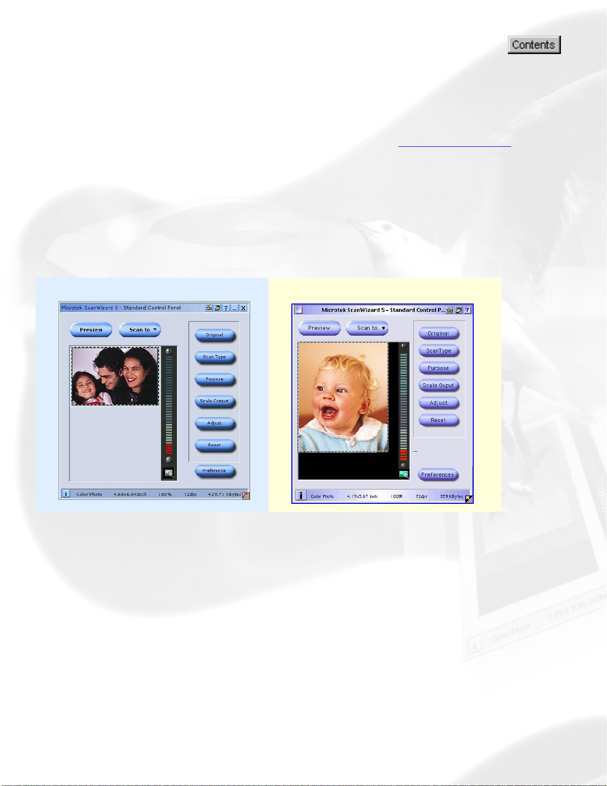
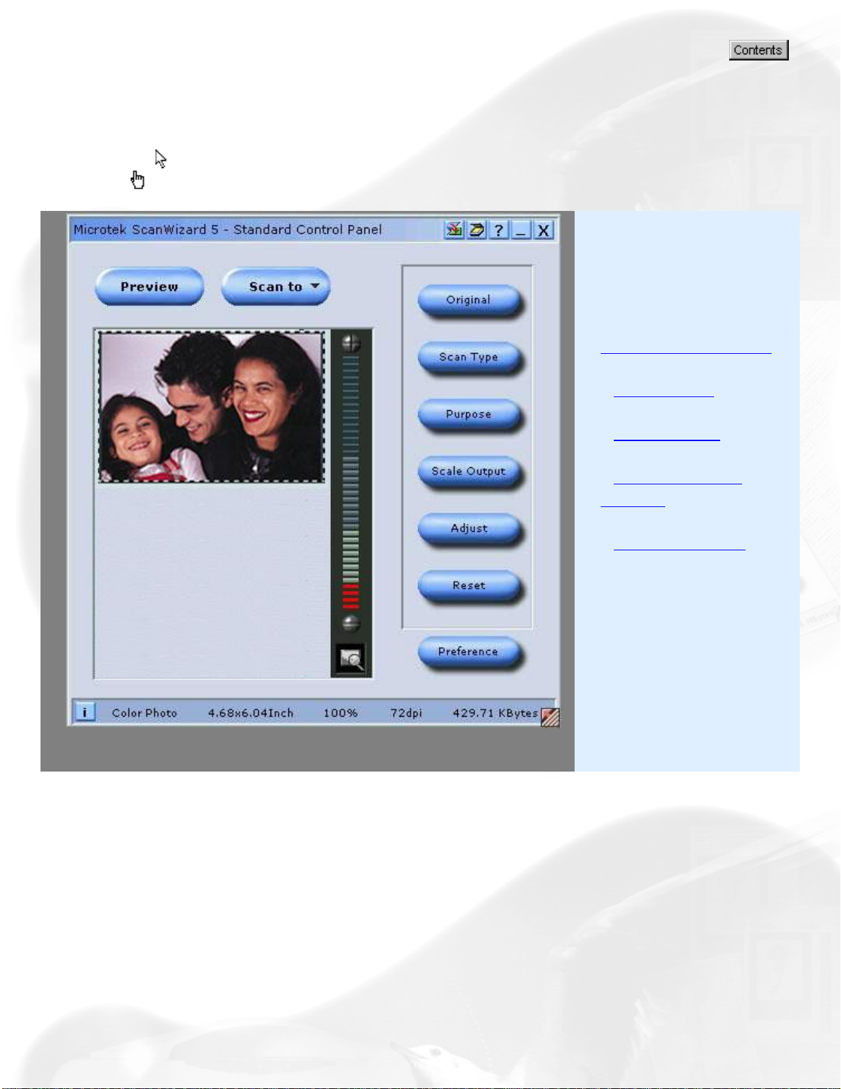
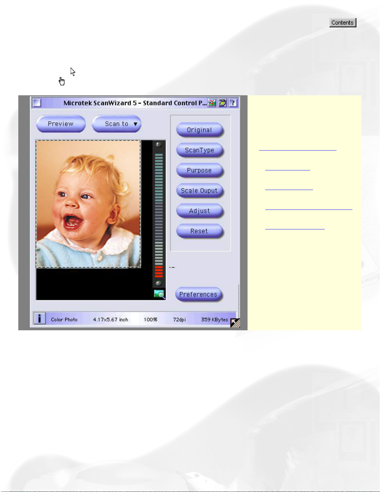
Standard Control Panel
The ScanWizard 5 - Standard Control Panel offers a simple and easy
way to complete a scanning session. It has a balloon tutorial that
can guide you through the actual steps to help you accomplish your
first scan.
To obtain a larger view and find out more about the functions
behind the Standard Control Panel, click either one of thumbnails
below:
Windows Macintosh
Page 5
Standard Control Panel
To view a brief information about the functions of the Standard Control Panel, position
the cursor
pointer
over any button, icon, or bar on the panel, and then click the grabber
to activate associated pop-up information dialog box.
Select the topic you
wish to view from the
links below to get a
hold of a more specific
explanation:
The Preview window
- Scan Frame
- Tool Buttons
- Final Scanning
Buttons
- Control Buttons
Page 6
Standard Control Panel
To view a brief information about the functions of the Standard Control Panel, position
the cursor
pointer
over any button, icon, or bar on the panel, and then click the grabber
to activate associated pop-up information dialog box.
Select the topic you wish
to view from the links
below to get a hold of a
more specific explanation:
The Preview window
- Scan Frame
- Tool Buttons
- Final Scanning Buttons
- Control Buttons
Page 7
Standard Control Panel
Preview window
By default, ScanWizard 5 - Standard Control Panel automatically
detects and creates a preview image of your original material in the preview
window when you first launch the program.
If you have disabled the auto-preview function under the "Preferences"
dialog box, you will need to manually click the Preview button to prescan
and preview your material.
Scan Frame Plotting, Moving, Re-sizing
Toolbar commands Original, Scan Type, Purpose, Scale Output, Adjust, Reset, Preferences
Final Scanning buttons Scan, Scan to, E-mail, Copy, OCR, To Web
Control buttons Panning tool, Zoom controls, i [Info], Arrow, Switch, Scanner info, Help [?], Exit
Scan frame
A Scan frame is a floating dotted-line border around a selected image.
Plotting
Moving
Resizing
Plotting
Page 8
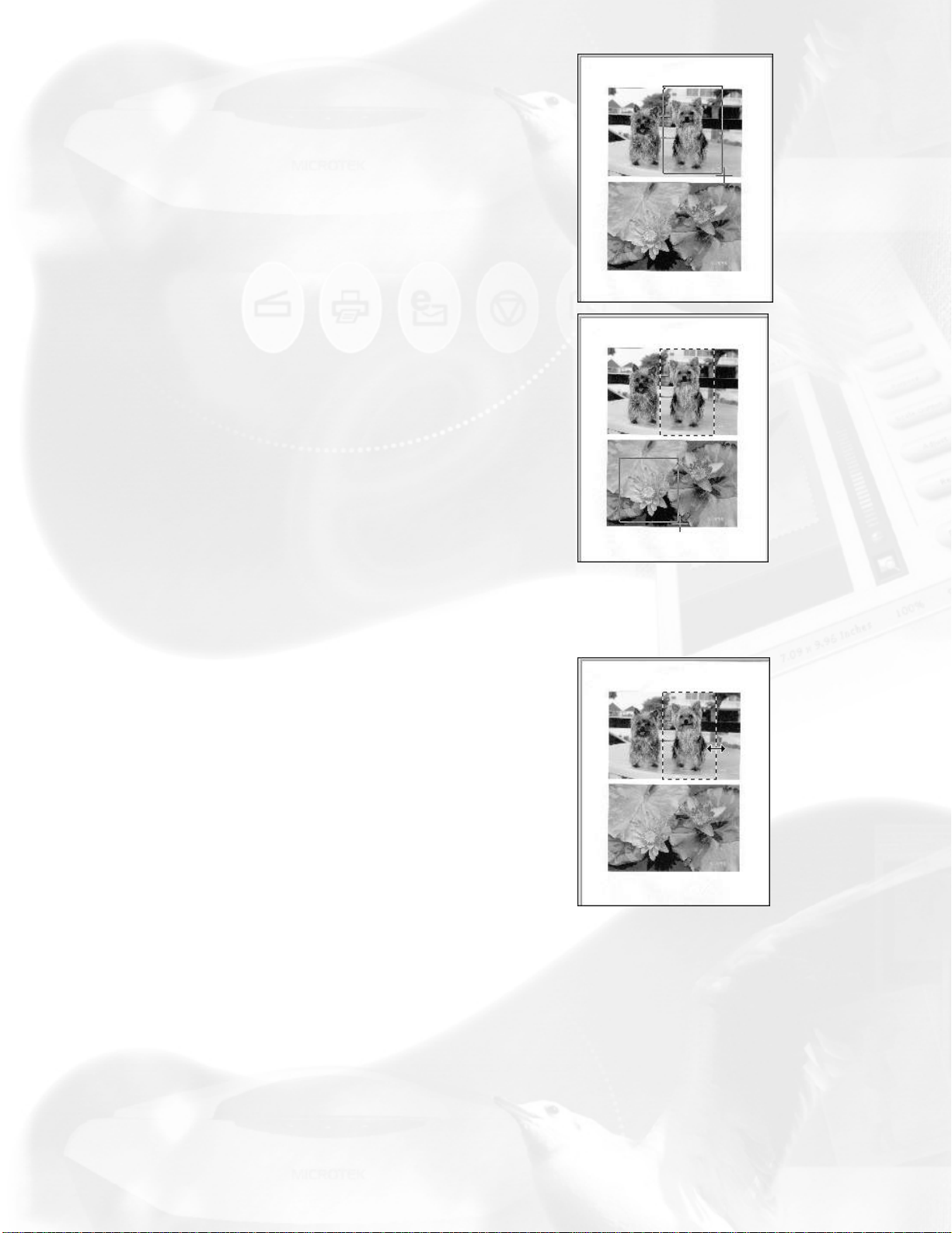
To plot a scan frame, point at any corner
of your intended scan frame. When the
crosshair pointer appears, drag diagonally
until you have the desired image selection
enclosed in a frame, and then release the
mouse. Your actual scan frame border
now turns into cascading lines.
To create a new scan frame over an
existing one or in another location of the
same preview image, follow the steps in
plotting a scan frame. When you release
the mouse, however, the previous scan
frame will be discarded.
Resizing
Point at any border of the scan frame until
a two-way arrow pointer appears. Drag
horizontally or vertically until you have
achieved the desired width and height
adjustments.
Moving
Page 9
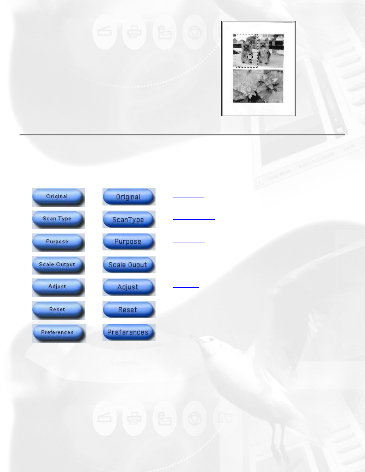
If you wish to use an existing scan frame
dimension to select another area of the
scan image, simply move the existing
scan frame over to the new area by
pointing anywhere within the existing scan
frame. When the four-way arrow pointer
appears, drag the scan frame to the
target area.
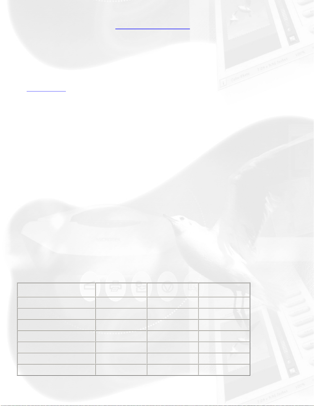
Toolbar commands
Windows Macintosh
Original
Scan Type
Purpose
Scale Output
Adjust
Reset
The Standard Control Panel's Toolbar commands are designed for selecting
your scan-setting requirements. There is no order or sequence required for
using the Toolbar commands in defining various aspects of your image.
Preferences
Original button
The Original button lets you select the type of material to be scanned.
ScanWizard 5 - Standard Control Panel determines the best scanning
parameters to automatically configure your original material.
Page 10
Options for selecting the type of scan material under the Original button
include: Photo, Text Document, Illustration, Printed Material, Film, etc.
Scan Type button
The Scan Type button allows you to select the image output to which the
original scan material will be converted. The options for choosing the output
image type are: True Color, Web Color, Gray, B&W, or JPEG.
Purpose button
The Purpose button displays a menu for selecting the intended usage of
the output image resolution. Different image resolution values are provided
for different output applications. The higher the resolution, the bigger
memory size required for uploading and downloading images.
This is your button for defining image output resolution to match the target
application (On-screen Viewing, Normal Screen, Ink-Jet Printing, and
Laser).
Select from the menu the particular setting that will best match the
intended device application for your output image. Different types of
originals may have different predefined resolution values as shown on the
table below.
If none of the predefined resolution matches your need, you may define
your own resolution by selecting "Custom" and then enter your own
resolution value in the Edit box provided at the bottom of the menu.
Remember that the higher the resolution, the larger the file size will be.
Normal Screen
Fine Screen
Ink Jet Printer
300 Laser Printer
600 Laser Printer
Text
Doc./Photo
72 72 72
96 96 96
300 200 300
300 100 300
600 150 300
+/- Film Graphic and
Magazine
Fax
OCR
200 200 200
300 300 300
Page 11

Scale Output button
This button lets you select image output resolution in terms of size/aspect
ratio. (50%, 75%, 100%, 150%, or 200 %).
Adjust button
This button is your basic image enhancement tool for modifying or
enhancing image(s) at the scanning stage.
It is suggested that you adjust the Brightness, Contrast, Sharpness, Color,
and Saturation of the preview image to enhance the output image. Click on
the Adjust button, and the Standard Control Panel image correction tool will
display. Adjust the image appearance by dragging the slider of each tool
along its grooves. Observe the changes from the preview image every time
you move each pellet button.
Reset button
This button will cancel your defined choices or revert to the default settings.
Preferences button
This button will give you access to the "Preferences" dialog box to set up
scanning function, and allows you to repaint or customize the appearance of
your Standard Control Panel.
The Preferences setup dialog box provides options on how you would like
ScanWizard 5 - Standard Control Panel to handle your scan material when
the program is launched.
To redefine Preferences setup, click on the Preferences button. From the
Preferences dialog box, select and choose your preferred options.
Automatically previews scan bed when launching ScanWizard 5
If checked, a reflective original overview will be carried out when
ScanWizard 5 is launched. If unchecked, no preview is carried out.
Auto-detect image type and find edges of photo or document
If checked, the scanner detects the image type when a preview is in
progress, and performs auto-cropping of the frame for reflective originals. If
unchecked, the image type can be chosen by the user, and a scan frame
can be set manually for cropping.
Page 12
Hide balloon screen tips
If checked, a balloon help pops up while the mouse pointer is on a button,
icon, or selection item. If unchecked, the balloon help becomes hidden and
inactive.
Auto Image Enhancement
If the "Auto Image Enhancement" option is checked, resulting image will
appear sharper, brighter, more realistic, and more saturated. If the "None"
option is selected, no image enhancement is applied.
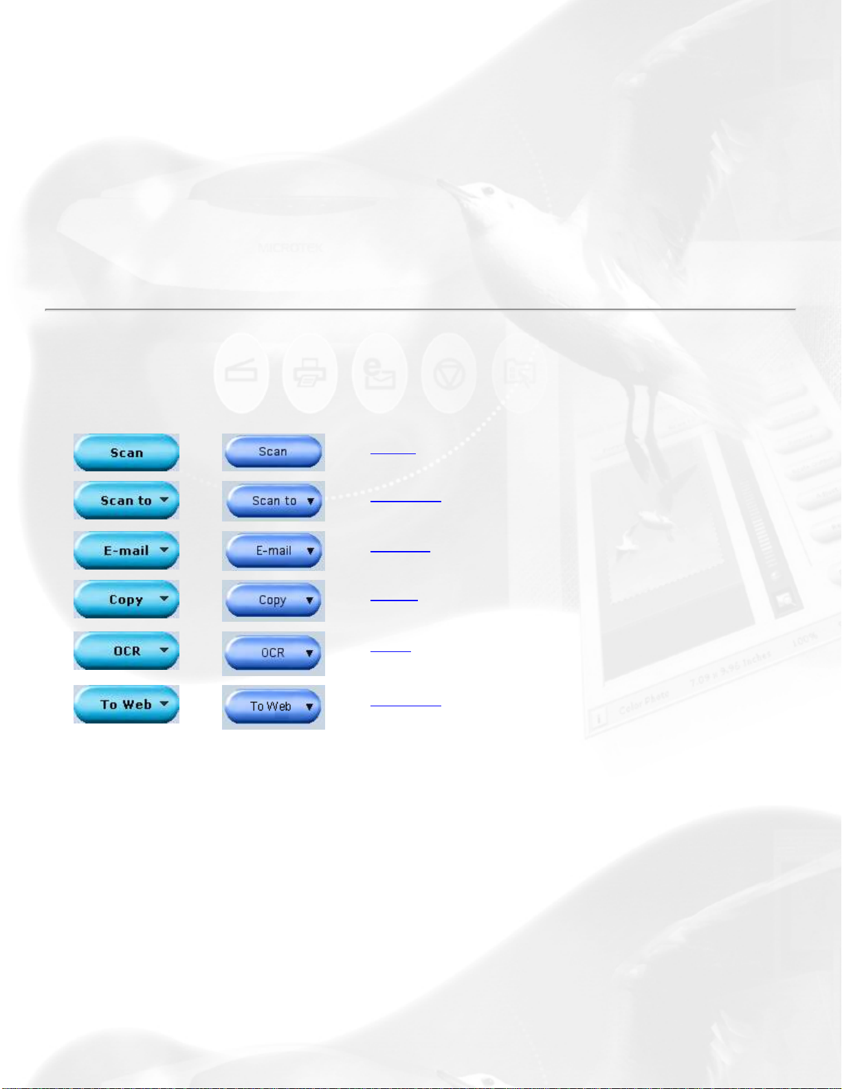
Final scanning buttons
Windows Macintosh
Scan button
Scan
Scan to
E-mail
Copy
OCR
To Web
This is the default button when ScanWizard 5 - Standard Control Panel is
launched from an image-editing application. It performs the final scan and
sends the scanned image (output) to the application that you are using.
Scan to button
When ScanWizard 5 - Standard Control Panel is launched as a stand-alone
program and is the default setting. This is also the default button on
scanners with the "Go" button feature.
Page 13

E-mail button
ScanWizard 5 automatically attaches the scanned image to your E-mail
message.
Point the cursor on the Scan or Scan to (whichever was activated
previously) button for a moment, then click and hold the button. Select E-
mail from the drop-down menu.
The Save As dialog box appears and prompts you to save the file to your
folder and key in a file name. It is recommended that you use either .jpg or
.bmp as the file format.
Make sure that the check box "Send document to application after saving"
has been selected/checked.
Make sure your preferred E-mail application is selected from the listed
options.
Click Save to launch your E-mail editor with the attached image, then start
typing your message and hit the Send button.
Copy button
Point the cursor on the Scan or Scan To button, then click and hold the
button for a moment. Select Copy from the drop-down menu.
When the Copy dialog box appears, select your default printer or any
alternative printer from the options, then specify the number of copies to be
made. When you are ready to print, click OK to create a copy of the
scanned material directly on your default printer.
The function of the Copy button is similar to the E-mail and OCR buttons.
OCR button
Point the cursor on the Scan or Scan to button, then click and hold the
button for a moment. Select OCR from the drop-down menu.
When the Save As dialog box appears, key in a file name, then select .rtf,
.txt, .xls, .htm, and pdf as the export file format.
Make sure that the check box "Send document to application after saving"
Page 14
has been selected/checked. Now, choose the Word processing application
from the options, and then click Save. The saved file can now be opened
from your chosen application, and is ready to be edited.
To Web button
Point the cursor on the Scan or Scan to button, then click and hold the
button for a moment. Select To Web from the drop-down menu.
ScanWizard 5 will check if the image size does not exceed the allowed file
size. When the "Microtek ScanWizard 5 - Scan to Web" dialog box appears,
save the file in your preferred folder, key in a file name, specify the file
type, and choose the website address from the options given.
The scanned image will automatically be uploaded directly to the
default/chosen website.
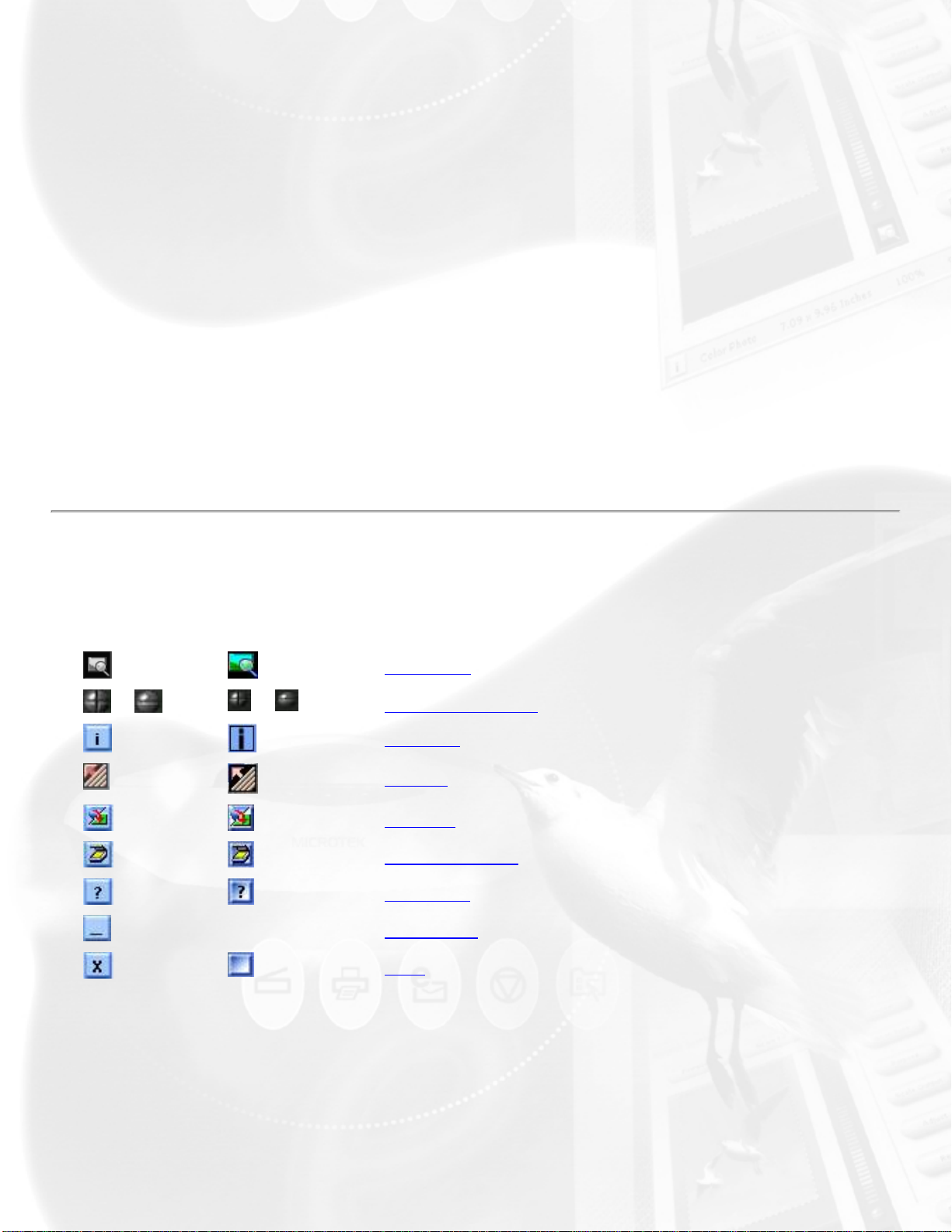
Control buttons
Windows Macintosh
/
/
-- Minimize
Pan tool
Zoom controls
i [Info]
Arrow
Switch
Scanner info
Help [?]
Exit
Pan tool
Pans or moves around a magnified preview area
Zoom controls
Page 15

(+) Zoom in button to magnify preview image
(-) Zoom out button to shrink preview image
i [Info]
The Info icon or status bar will show a summary of current configuration
settings on the current image and also becomes a progress bar during
scanning. Click this icon for more detailed configuration info.
Arrow
This is your button for resizing the preview window. Simply drag the Arrow
icon (located at the bottom right corner of the panel) to adjust the size of
the window.
Switch
This icon enables you to change/switch to the Advanced Control Panel and
the Standard Control Panel, respectively.
Scanner info
Click the Scanner info icon to access the "Scanner Control and Scanner
Information" options menu.
ScanWizard 5 is constantly in touch with your scanner, monitoring scanner
availability and serviceability, as well as its make and mode. To see how
your scanner is doing, simply click this icon from the title bar.
Help [?]
On-line help:
To access On-line help, click on the Help icon, then select Help.
Tutorial Guide:
To access the balloon tutorial, click on the Help icon, then choose Tutorial
Guide.
About ScanWizard 5:
To learn more about the version and release date of your ScanWizard 5,
click on About from the Help icon. The ScanWizard 5 splash screen will
appear.
Page 16
Minimize
Windows:
Macintosh: (Not available)
To minimize ScanWizard 5, click on the Minimize located
at the top right corner of the Control Panel.
Exit
Windows: To close ScanWizard 5, click on Exit located at the top
right corner of the Control Panel.
Macintosh: Exit is located at the top left corner of the Standard
Control Panel.
Take note that when you exit, you quit from both standard and advanced
modes of ScanWizard 5.
Page 17
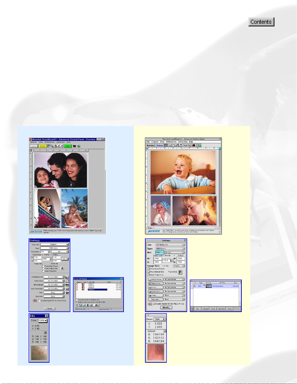
Advanced Control Panel
The ScanWizard 5 - Advanced Control Panel provides users the
power to specify, correct, and improve the image at the scanning
stage. Learn how to use the basic functions in the Advanced Control
Panel to scan like a pro.
To learn more, click any of these four windows--related to your
computer's Operating System (OS).
Windows Macintosh
Page 18
Advanced Control Panel
Preview window
To view information about the functions of the Advanced Control Panel, position the cursor
over any button, icon, or bar on the panel. Click the grabber pointer
help information. Or select the topic that you wish to view from the links below:
Menu bar, Control buttons, Final Scanning buttons, and Toolbar.
to activate associated
Preview area,
The Advanced
Control Panel,
Settings, Info, and
Scan Job Queue
windows appear
when ScanWizard 5 Advanced Control
Panel is activated for
the first time.
Settings
window
Info window
Scan Job window
Page 19
Advanced Control Panel
Preview window
To view information about the functions of the Advanced Control Panel, position the cursor
over any button, icon, or bar on the panel. Click the grabber pointer
help information. Or select the topic that you wish to view from the links below:
Menu bar, Control buttons, Final Scanning buttons, and Toolbar.
to activate associated
Preview area,
The Advanced Control
Panel, Settings, Info, and
Scan Job Queue windows
appear when ScanWizard 5
- Advanced Control Panel is
activated for the first time.
Settings window
Info window
Scan Job Queue
window
Page 20
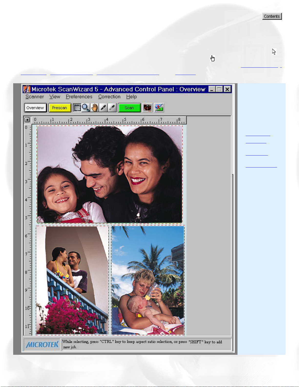
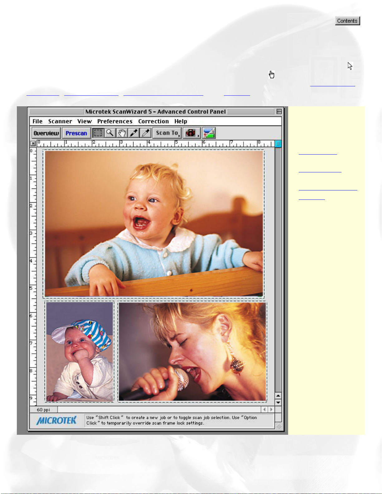
Advanced Control Panel
Preview window
The Preview window is the main window of the four windows. The Preview
window is where your image appears after you click on the Overview or
Prescan button.
Preview area Preview image information
Menu bar Scanner, View, Preferences, Correction, Help
Control buttons Overview, Prescan, Scan Material, Switch, Unit of Measurement/Ruler, Exit, Minimize, Shrink
Final scanning buttons Scan, Scan to, E-mail, Copy, OCR, To Web
Toolbar Scan Frame, Zoom, Pan, Pickers
Preview area
The preview area is where the preview image appears.
The dimensions of the preview area vary, depending on your scanner
model. The size of the preview area can be modified through the Overview
Setup command in the Preferences menu. You can increase the size of the
preview area to see more detail in your image, or you can reduce the
preview area to fit more information on your monitor.
Menu bar
The menu bar includes the different menus for setting up the scanner.
Scanner menu To view the status and technical information about your scanner
View menu To modify the ScanWizard 5 windows
Preferences menu To customize how the image is processed
Correction menu Contains the Advanced Image Correction items
Page 21
Help menu To access on-line help
Control buttons
The Control buttons generate a specific action from the scanning software.
The buttons include: Overview, Prescan, Scan Material, Switch, Unit of
Measurements/Rulers, Status bar, Resize, and Exit.
Windows Macintosh
-- Exit
Minimize (Shrink for Macintosh)
Unit of Measurement/Ruler
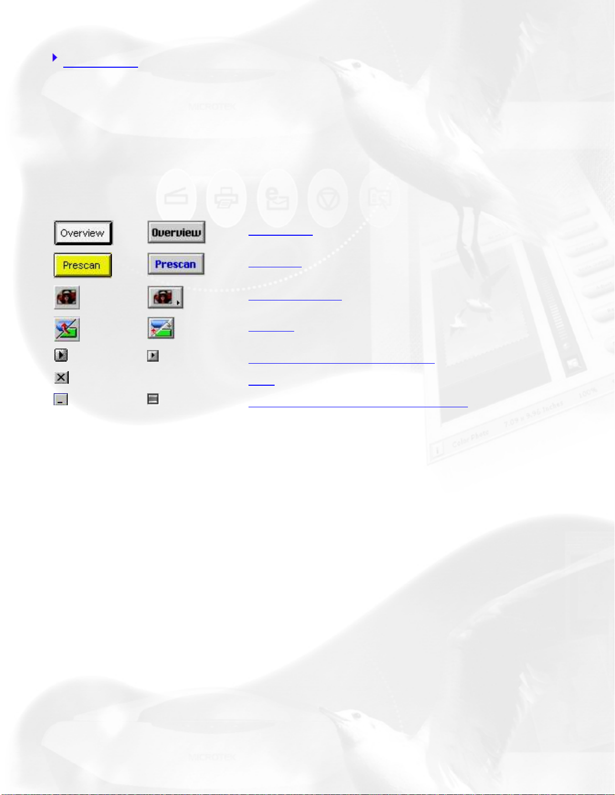
Overview
Prescan
Scan Material
Switch
Overview button
The Overview button creates a low-resolution preview.
Prescan button
The Prescan button creates a high-resolution preview.
Unit of Measurement/Rulers
The rulers on both sides of the preview window assist you in measurement
or in checking the alignment of your image.
The unit of measurement in the ruler can be selected in two ways: in the
Image Dimension controls located in the Settings window, or by clicking on
the ruler unit button at the 0,0 point of the rulers in the Preview window.
Depending on your selection, the rulers can mark off measurement in these
units: inch, centimeter, millimeter, point, and pixel. The pixel option is
Page 22
dimmed if the selected resolution unit is lpi, and vice versa.
To select the unit of measurement for the rulers:
Click on the unit box in the Settings window, or click on the ruler unit
button
submenu appears, select the unit of measurement.
at the 0,0 point of the rulers in the Preview window. When the
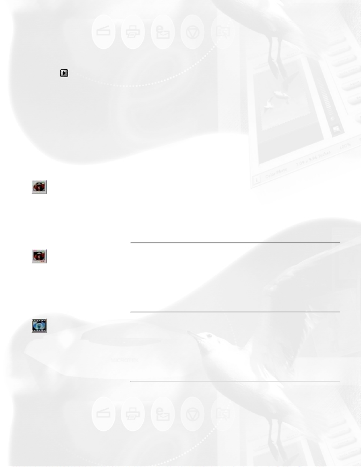
Scan Material icon
Access the Scan Material menu by using the Scan Material icon, located to
the left of the Switch button.
The appearance of the Scan Material icon changes, depending on whether
your scan material is reflective, positive, or negative.
If you are scanning reflective materials (such as
Appearance of the Scan
Material Status icon
when scanning
reflective materials
photos or printed material), this is the
appearance of the Scan Material icon. When you
click on the icon and hold down the mouse, you
will see the Reflective option checked.
If you are scanning a positive transparency or
Positive transparency
or filmstrip
Negative transparency
or filmstrip
filmstrip, this is the appearance of the Scan
Material icon. When you click on the icon and
hold down the mouse, you will see the Positive
Film option checked.
If you are scanning a negative transparency or
filmstrip, this is the appearance of the Scan
Material icon. When you click on the icon and
hold down the mouse, you will see the Negative
Film option checked.
Switch icon
This icon enables you to change/switch to the Advanced Control Panel and
the Standard Control Panel, respectively.
Page 23
Exit [X]
To close ScanWizard 5, click on the Exit button located at the top right
corner of the Control Panel for Windows, or select Quit from the File menu
for Macintosh.
Take note that when you exit, you quit from both standard and advanced
modes in ScanWizard 5.
Minimize/Shrink
Windows: To minimize ScanWizard 5, click on the Minimize button
located at the top right corner of the Control Panel.
Macintosh: To shrink Advance Control Panel, click on the Shrink
button located at the top right corner of the Control Panel.
Status bar
The status bar provides helpful tips when you click any button on the panel.
Resize
Simply drag the bottom right corner of the Advanced Control Panel to
adjust the size of the Preview window.
Final scanning buttons
One of ScanWizard 5's great features is the productivity tools under the
Scan button. Click and hold the mouse button to activate the options menu
and select either Copy, E-mail, OCR, or To Web.
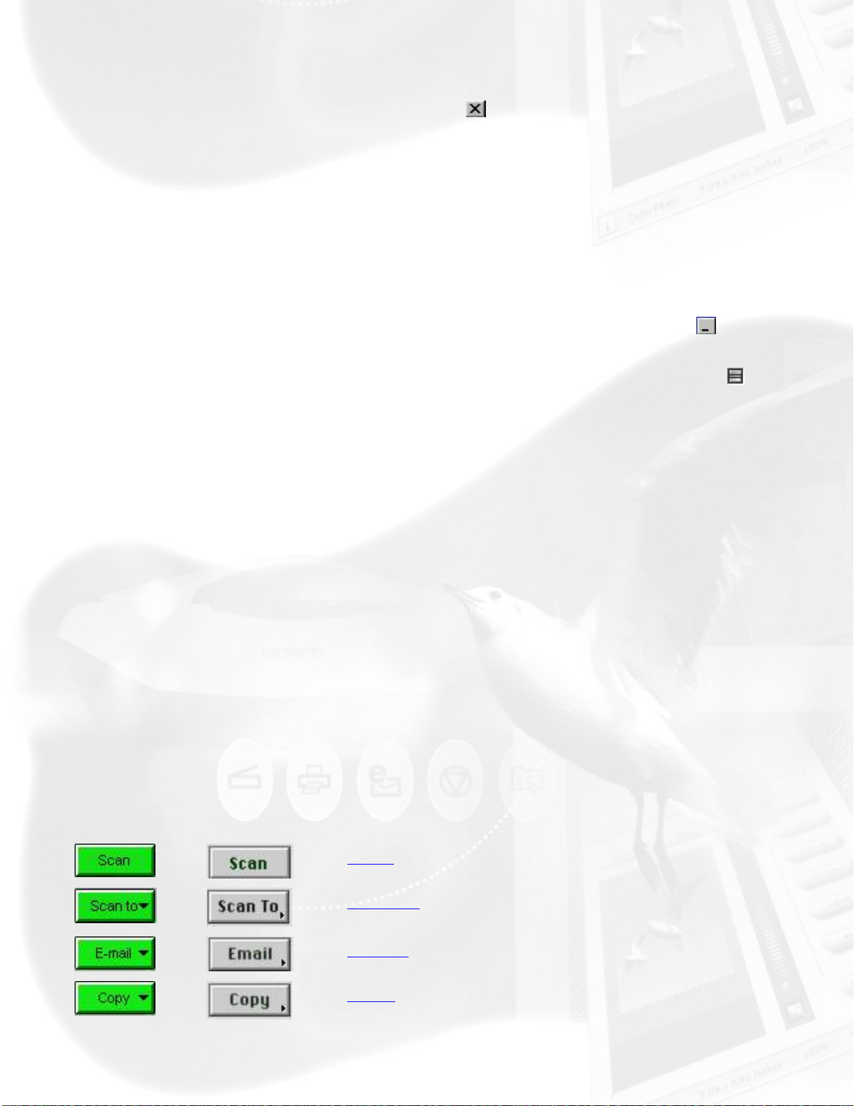
Windows Macintosh
Scan
Scan to
E-mail
Copy
Page 24
OCR
To Web
Scan button
This is the default button when ScanWizard 5 - Advanced Control Panel is
launched from an image-editing application. It performs the final scan and
sends the scanned image (output) to the application that you are using.
Scan to button
When ScanWizard 5 - Advanced Control Panel is launched as a stand-alone
program and is the default setting. This is also the default button on
scanners with the "Go" button feature.
E-mail button
ScanWizard 5 automatically attaches the scanned image to your E-mail
message.
Point the cursor on the Scan or Scan To (whichever was activated
previously) button, then click and hold the button for a moment. Select E-
mail from the drop-down menu.
The Save As dialog box appears and prompts you to save the file to your
preferred folder and key in a file name. It is recommended that you use
either .jpg or .bmp as the file format.
Make sure that the check box "Send to application after saving" has been
selected/checked.
Make sure your preferred E-mail application is selected from the listed
options.
Click Save to launch your E-mail editor with the attached image, then type
your message and hit the Send button.
Copy button
Point the cursor on the Scan or Scan To button, then click and hold the
Page 25

button for a moment. Select Copy from the drop-down menu.
When the Copy dialog box appears, select your default printer or any
alternative printer from the options, then specify the number of copies to be
made. When you are ready to print, click OK to create a copy of the
scanned material directly on your default printer.
The function of the Copy button is similar to the E-mail and OCR buttons,
but the image goes directly to your default or selected printer.
OCR button
Point the cursor on the Scan or Scan To button, then click and hold the
button for a moment. Select OCR from the drop-down menu.
When the Save As dialog box appears, key in a file name, then select .rtf,
.txt, xls, .htm, or .pdf as the export file format.
Make sure that the check box "Send document to application after saving"
has been selected/checked. Then choose the word processing application
from the options, and click Save. The saved file can now be opened from
your chosen application and is ready to be edited.
To Web
Point the cursor on the Scan or Scan to button, then click and hold the
button for a moment. Select To Web from the drop-down menu.
ScanWizard 5 will check if the image size does not exceed the allowed file
size. When the "Microtek ScanWizard 5 - Scan to Web" dialog box appears,
save the file in your preferred folder, key in a file name, specify a file type,
and choose the website address from the options given. The scanned image
will automatically be uploaded directly to the default/chosen website.
Note: If you have not created an account with iMira.com -- you can do so
now by clicking the "Create a new account for photo Sharing" button from
the same dialog box to enable access and to speed up the process of
uploading images directly to the Web.
Toolbar
The Toolbar commands simplify the performance of certain tasks. The
Page 26
Toolbar commands include Scan Frame, Zoom, Pan, and Pickers.
Windows Macintosh
Scan Frame
Zoom
Pan
Pickers
Scan Frame tool
The Scan Frame lets you create a single scan frame or multiple scan
frames in the preview image, which is the active area on which controls and
commands can be applied.
The Scan Frame can also be used to create batch scans. The current scan
frame is indicated by a marquee (cascading border). The current scan
frame can be more easily distinguished if you turn on the Smoked Glass
Background command (in the Preferences menu).
Zoom tool
The Zoom tool enlarges your view of the preview image, allowing you to
set the scan frame with greater precision if you need to. Only your view of
the preview image is changed; the actual output size of the image remains
unaffected.
Each click of the Zoom tool magnifies or reduces image view by a factor of
2. Thus, the magnification levels increase from 100% to 200%, to 400%,
and to the maximum of 800%.
Note: If the Info window is open, the zoom level will be indicated. This
means you can also zoom in by selecting the appropriate zoom level in the
Info window.
Pan tool
The Pan tool lets you scroll through a preview image, allowing you to move
parts of the image into view.
Page 27
The Pan tool can be used for zoomed-in images (enlarged through the
Zoom tool), or images not completely displayed within the frame of the
preview window (for instance, if your preview image is 7 inches wide and
you resized the width of your overview/preview window to only 3 inches).
White / Black Point Picker tool
The Picker tools allow you to sample color from a particular area in an
image, and are useful for designating shadow or highlight point.
The White Point Picker ( / ) lets you define the whitest reference point
in the preview image. Once you have picked the whitest point, excessive
white points are clipped off.
The Black Point Picker ( / ) lets you define the darkest reference point
in the preview image. Once you have picked the darkest point, excessive
black points are clipped off.
With the Picker tools, you can determine the color values for any pixel in an
image. When you click on the White/Black Picker and pan over a pixel, the
value for that pixel is displayed in the Info window, based on the sample
size selected in the Info window. Pixel value information is useful especially
when you are making color adjustments based on color value.
To change the sample size of the Picker tool:
1. Open the Info window by choosing the Show Info Window command in
the View menu.
2. Click on the Color Meter Options button located to the right of the
RGB values in the Info window.
3. Choose your options.
Select the sample size options from the drop-down list. For instance, the 1
by 1 option will display the value of one pixel — the one in the middle of the
Color Output Meter. The 3 X 3 option reads the average value of a 3-pixel
by 3-pixel area.
To display color information for a pixel or an averaged area:
1. Click on the Picker tool.
Page 28

2. As you pass over a point in the image, observe the Info window — the
RGB values will be displayed in the Color Output Meter. These values
are in turn based on the sample size you selected.
Page 29
Advanced Control Panel>Preview window
Menu bar
Scanner menu
View menu
Preferences menu
Correction menu
Help menu
File menu (for Macintosh only)
Scanner menu
The Scanner menu includes the following:
Scanner Model
Get Current Scanner Info
Scanner Probe
Scanner Driver Manager (for Macintosh only)
Scanner Model
The top of the scanner menu displays the scanner model you are
using and its Scanner ID. If you have multiple scanners on your
system, all the scanners are shown with their respective Scanner
IDs, and the current scanner is indicated by a check.
Page 30

Only one scanner can be accessed at a time. To switch among
various scanners, select the scanner to be used.
Get Current Scanner Info
This command provides information about your current scanner.
When you choose this command, a dialog box appears showing the
scanner model, Scanner ID number, and firmware version.
Scanner Probe
This command displays the detected scanner devices.
If your scanner does not show in the list, make sure your scanner is
connected and turned on, then click on the Probe button in the
dialog box.
Scanner Driver Manager (for Macintosh only)
The Scanner Driver Manager keeps track of the scanners being used
on your system and the interface bus/ID numbers occupied by the
scanners. By keeping a record of this information, the Scanner
Driver Manager allows ScanWizard 5 to start up more quickly, as
there is no need to look for devices on the other interface buses.
To find a scanner:
Follow the hardware installation instructions for connecting a
scanner to your system. Then you can use the Scanner Driver
Manager in ScanWizard 5 to find the connected scanner in your
scanner list.
1. Go to the Scanner menu in the Preview window, and choose
Scanner Driver Manager. A dialog box will appear showing the
connected scanner and the corresponding interface ID
number.
2. Click the Find Scanners button. In case you have added new
Page 31

scanners, the newly found scanners will be appended to the
scanner list. If a scanner on the list is not detected (not turned
on, not ready, or removed from the system), the model will
not be removed from the list but will have a question mark
before it.
3. Click the Close button to close the dialog box.
To remove a scanner from your scanner list:
1. Go to the Scanner menu in the Preview window, and choose
Scanner Driver Manager.
2. Click the Remove button to delete the scanner model from
your scanner list.
3. Click the Close button to close the dialog box.
Update List
This command refreshes the SCSI buses and updates the Scanner
menu with the current scanner list.
This is most useful when ScanWizard 5 is brought up but one of the
scanners is not turned on or has not become ready.
Only the current scanner list is used, and ScanWizard 5 will not find
or add any new scanners to the scanner list. This is a short-cut
command without invoking the Scanner Driver Manager.
View menu
The View Menu includes the following:
Overview or prescan image
Page 32

Resize window to fit
Bring Settings window to front
Show/Hide (Info, Scan Job Queue windows, and Status bar)
About (for Macintosh only)
Overview Image and Prescan image
These commands select the image obtained with the Overview and
Prescan buttons, respectively, and allow you to switch between both
viewing modes.
The dimensions of the Overview image and Prescan image are
controlled by the Overview Setup command and the Prescan Setup
command, respectively. For more details, see these commands
under the
To obtain the Overview image:
With the image(s) placed on your scanner, click the Overview
button.
To obtain the Prescan image:
1. Click the Scan Frame tool.
2. Select the area to be prescanned by drawing a frame around
the area in the Overview image.
Preferences menu.
3. Click the Prescan button.
To obtain multiple Prescan images:
1. Define your scan jobs in the Scan Job Queue window.
Page 33

2. To select multiple scan jobs, press the Shift key and click on
the jobs to be selected in the Scan Job Queue or Preview
window.
3. Click the Prescan button in the Preview window. Multiple
prescans are created in the process, corresponding to the
number of scan jobs defined, and you can then switch among
the various prescan images.
Resize Window to Fit
This command resizes the Preview window, which you may find
helpful for conserving space on your desktop monitor especially
after enlarging the Preview window.
To verify the zoom level, open the Info window (choose Show Info
Window command from the View menu), and look up the zoom
level.
Bring Settings Window to Front
This command brings the Settings window to the forefront, which is
useful if you have the Settings window hidden behind other
windows or if you have expanded your Preview window such that it
hides the Settings window in the background.
Show/Hide windows
These commands allow you to switch between showing or hiding the
Scan Job Queue and the Info windows.
To use this feature, choose the correct command from the View
menu for viewing a window. When the window appears, you can
hide it by choosing the particular Hide command for it.
About (for Macintosh only)
This command displays the ScanWizard 5 splash screen and shows
Page 34

program version and copyright information.
Preferences menu
The Preferences menu includes the following:
Scan Material
Color Matching Setup
White/Black Points Setup
Cursor Auxiliary Lines
Overview Setup
Prescan Setup
Monitor Gamma Setup (for Windows only)
Invert
More...
Retain Scan Module after Scan (for Macintosh only)
Scan Material
This command allows you to select your scan material, which can be
one of the following:
● Reflectives, such as photographs or prints.
Page 35

● Positives, such as slides.
● Negatives, such as the negative film you use for your camera.
The default scan material depends upon the scanner you are using,
and the choices available to you in the Scan Material submenu will
also depend on your equipment.
If you are scanning negatives or positives, make sure you specify
the correct scan material, or you will get inaccurate scanning
results.
To select the scan material:
1. Choose the Scan Material command in the Preferences menu.
From the submenu that appears, select your scan material.
2. Alternatively, you can also click the Scan Material icon
(adjacent to the Switch button), and then choose the correct
scan material from the drop-down menu that appears.
Color Matching Setup
Color Matching is an important feature of ScanWizard 5 that
ensures color is displayed consistently — from the initial input stage
when an image is captured by the scanner, to the final output stage
when the image is output to your monitor or printer (through either
the Kodak CMS or Apple ColorSync™ technology). Color matching
was developed to allow an equivalent "mapping" of colors from one
device or from one color space to another, ensuring that no major
color shifts occur in the transference process.
To use the ScanWizard 5 color matching function:
1. Set up the Kodak CMS and Apple ColorSync features correctly
at the time that ScanWizard 5 is installed. For more
information on this procedure, refer to your Kodak or Apple
system documentation.
Page 36

2. The first time you launch ScanWizard 5, you will be prompted
to set up color matching for your scanner. You may also
access the color matching parameters for ScanWizard 5 at any
time in the future, by choosing the Color Matching Setup
command in the Preferences menu. ScanWizard 5 includes
several industry-standard ICC color profiles.
Display using monitor compensation
This box pertains to how your monitor displays color, relative to the
RGB Destination color space. It is best to have this box checked so
that there are no unexpected color shifts between your selected
RGB Destination space and your monitor.
Monitor
Windows: This feature lets you select the type of color
monitor that is used for displaying RGB
data. The monitor profile will be applied
only when "Displaying using monitor
compensation" option is checked.
Note: If the available monitor types do not
include the one you have, select Generic
P22 or Generic EBU. These two profiles are
suitable for most monitors.
Macintosh: The monitor selection shown here is the
monitor set in your Apple ColorSync Control
Panel.
To verify this information, go to your Apple
Menu, select Control Panel, then Color Sync.
Your selected monitor will be shown, which
should be the same as the entry in this
dialog box.
Note: This setting only affects how the
image is shown on the screen — not the
final scanned image.
Page 37

RGB Color Matching
This box should generally be checked unless you want to scan raw
color data, in which case you lose the compensatory effects of the
Color Matching system. On the other hand, if this box is unchecked,
all images will be scanned without any color matching processing.
Note: It is not desirable to scan in raw data and then perform
ColorSync data conversion, which will not generate the correct CMS
effect.
RGB Destination
Windows: This feature lets you select the RGB output
device (e.g display monitor, or RGB-based
printer) for matching RGB Color family
images (including RGB colors, 48-bit RGB
colors, and 256 colors image types).
Macintosh: This feature lets you select the ICC profile in
the ColorSync profile folder for outputting
images to the RGB color space.
You may select from monitor, RGB printer
(e.g., inkjet printers), a special color space,
or the Adobe Photoshop 5.0 internal color
space profile. For Photoshop 5.0 users, this
should always be the same as your RGB
working space as defined in the Photoshop
5.0 RGB Setup.
Color Enhancement (for Windows only)
This box has two options: Automatic and None. Before selecting the
"Automatic option, the RGB Color Matching option should be
checked first. If the Automatic option is selected, a color
enhancement algorithm applies to the scanned image, and the
resulting image appears brighter, more realistic, and more
Page 38

saturated. If the "None" option is selected, the scanned image will
appear as similar as the original.
Info/Profile Information button
This lets you get information on currently used ICC profiles.
Preview check box (for Macintosh only)
This immediately updates the Preview window image when a new
color profile is selected. This will reflect colors consistent with the
newly selected profile.
White/Black Points Setup
The White Point is a reference point that specifies the lightest area
in an image. The Black Point is the darkest reference area.
Auto White Point Clipping
This lets you set the percentage of pixels in the highlight region to
be truncated. Effective only when “Auto White/Black point” option is
selected in the AIC dialog box.
Auto Black Point Clipping
This lets you set the percentage of pixels in the shadow region to be
truncated. Effective only when “Auto White/Black point” option is
selected in the AIC dialog box.
Minimum Output level
This lets you set the minimum output level of the Black Point. The
higher the percentage value, the lower the contrast.
Maximum Output level
This lets you set the maximum output level of the White Point. The
lower the percentage value, the lower the contrast.
Page 39

Cursor Auxiliary Lines
This command allows you to create horizontal and vertical grid lines
with your cursor to help define a scan frame precisely. Using the
grid lines, you can also read the measurements of your ruler more
easily.
To use this feature:
1. Choose the Cursor Auxiliary Lines command in the
Preferences menu. From the submenu that appears, select
how the cursor lines will appear.
● On both x (horizontal) and y (vertical) axes
■ On x axis only
■ On y axis only
■ None (no cursor lines)
2. Click on the Scan Frame tool.
To see how the cursor lines work, draw a scan frame.
Click on the top left corner of the image as your starting
point, then drag down diagonally to form a scan frame.
As you draw the scan frame, cursor lines will appear to
help you draw the scan frame precisely. When you
release the mouse, your scan frame will be aligned with
the cursor lines.
Overview Setup
This command lets you set the area you want to be overviewed of
the scan bed, and provides some overview options as well.
By default, ScanWizard 5 overviews the maximum scan area as
determined by your scanner model's bed size. You can, however,
Page 40

customize the overview area so that the scanner consistently
overviews only the specific dimensions you have in mind. For
example, if your maximum scan area is 8.5" x 14", you can
customize the overview area so that it consistently overviews, say,
4" x 8" of the bed size.
As a rule of thumb, it is best to use the default maximum settings.
You should change the overview area only if your subsequent
overview is too large to be shown in entirety, or too small for
reliable previewing. A smaller overview area will increase the
overview resolution for clearer image viewing. You may also wish to
change the size of your overview to improve performance.
Generally, a shorter overview time results from the scanner motor
travelling at a lesser distance.
Fast Overview/Fast
The Fast Overview/Fast option supports faster scanning. If Fast
Overview is unchecked, the Overview scanning speed is slow, but a
better overview image quality is obtained.
Overview Area
Choose Maximum Size, other fixed dimensions, or choose Custom
Size, then enter the required dimensions. You may also set the
Overview Area by dragging the dotted borders.
Unit
This lets you set the ruler units such as inch, cm, and mm.
Preview/Overview button
Click this button to get a scanning preview, or to do a new
overview. This is helpful if you have specified custom settings or
changed the dimensions.
Prescan Setup
Page 41

This command allows you to set the parameters for scanning a
prescan image. The major difference between Overview and
Prescan is that the Overview button scans the area specified in the
Overview Setup command for getting a low-resolution preview
image, whereas the Prescan button only scans the selected
scanning frame, resulting in a more detailed preview image. When
the Prescan Setup dialog box comes up, click on the option you
need or specify your parameters.
Fast Prescan
If checked, you get a coarser or lower-quality image is obtained but
at a faster scanning speed. If unchecked, a better- quality image is
obtained but at a slower scanning speed.
Prescan Image Margin
This option allows you to specify margin around the scan job in the
first place, subsequently you can adjust the scan frame slightly in
the Prescan mode. Available options are: None, Small, Medium
(default), and Large.
Prescan Image Dimension
This option allows you to specify the size of the prescan image.
Available options are: Full screen, 75% screen, 50% screen, and Fit
Preview Window. Size of the Prescan image does not necessarily fit
into the specified option, as it is based only on the height/width
ratio to get the maximum covered area.
Monitor Gamma Setup (for Windows only)
The Monitor Gamma Setup command lets you compensate for the
linear intensity of the monitor, allowing for consistency between the
preview image and the final scanned image.
Monitor Gamma
Check this box to enable monitor gamma value setting.
Page 42

When the monitor gamma option is checked, click the up/down
arrow buttons to make the gray level of the boxes as close as
possible. Click OK to confirm.
Invert
This command creates a negative effect to an image. The Invert
effect is applied to all scan jobs, not just the selected scan job.
When an image is inverted, the brightness value of each pixel is
converted to the inverse value on the 256-step color values scale.
For example, a pixel in a positive image with a value of 255 is
changed to 0, and a pixel with a value of 5 is changed to 250.
Before After
To use this feature:
Choose the Invert command in the Preferences menu. A check (V)
appears next to the command when it is enabled.
Retain Scan Module after Scan (for Macintosh only)
This command allows you to keep the ScanWizard 5 interface
running after scanning is completed and after the image has been
delivered to your image-editing software. This way, there is no need
to go back to the File-Acquire process to start ScanWizard 5 all over
again.
Page 43

Note: This command can be used only in applications (such as
Adobe Photoshop) that allow you to retain the scan module after a
scan is completed. Some applications may not retain the scan
module even if this option is enabled.
To use this feature:
Choose the command Retain Scan Module after Scan in the
Preferences menu. A check (v) appears next to the command when
it is enabled. If you wish to see the scanned image in your imageediting software after scanning is completed, you will need to quit
ScanWizard 5 to see the image.
More... command
The More... command lets you specify, miscellaneous parameters.
Keep Overview Image
If checked, the image which is prescanned in the Overview
command remains on the screen until the next image acquisition is
performed. If unchecked, the overview image is deleted when you
exit ScanWizard 5.
Keep All Prescan Images
If checked, the image which is prescanned in the Prescan command
remains on the screen until the next image acquisition is performed.
If unchecked, the prescanned image is deleted when you exit
ScanWizard 5.
Confirmation Message (for Windows only)
If checked, a confirmation message appears when image effects
such as Rotate or Flip are applied. If unchecked, no confirmation
message appears.
Smoked Glass Background
This command helps in distinguishing the current scan frame from
Page 44

the rest of the preview image for greater visibility of the current
scan frame.
With the Smoked Glass feature turned on, the part of the image
within the current scan frame will stand out, while the rest of the
image (the “irrelevant” material) is relegated to a background
resembling smoked glass.
Before After
The Smoked Glass Background, helps you focus on the part of the
image within the current scan frame, and is particularly helpful
when you are editing a scan frame or applying image-correction
controls. This way, the changes can be seen more clearly and stand
out from the rest of the material. (See the next section for more
details. )
Scan Quality selection
During a scan, the following selections are available:Speed, Quality,
and Best Quality.
Speed:
Higher scan speeds are obtained, but lower image quality results in
the process.
Quality:
If “Quality” option is selected, the scanning carriage slows down
Page 45

while the CCD is exposed to the light source. As a result, a better
image is achieved. Most scan materials can get a quality scan if this
mode is chosen.
Best Quality:
This option is available for 10- or 12-bit scanners only. The CCD
exposure scheme is much the same as the “Quality” option, but
image correction is first applied to the 10- or 12-bit image, then the
image is converted to 8-bits. RGB Colors (48-bit) image is always
scanned in Best Quality option regardless of the option selected.
This option is useful for scanning originals of lower quality and for
performing image correction without losing detailed information.
Note: This option is useful for scanning Line art images to keep
edges smooth; e.g., edges of a logo.
Working Directory
This lets you specify a place to store temporary working files (e.g.,
scan job files) during a scanning session. If the directory you
specify is not found or does not exist, a warning message appears,
and ScanWizard 5 will create one automatically for you.
If the computer is shared by several users, each user may specify a
particular working directory to use..
Memory Usage (for Macintosh only)
This option controls the way ScanWizard 5 uses memory. Three
options are provided:
Auto:
This is the default setting. ScanWizard 5 maximizes memory usage
from both system and application, looking for memory first from the
system heap and then from the application heap.
Application:
ScanWizard 5 will only use the memory inside the application heap
as its image buffer. Make sure you allocate a large number of
Page 46

memory in your application for this purpose; otherwise, ScanWizard
5 may not have enough memory to run. Use this option only if you
do not want ScanWizard 5 to use memory outside your application.
System:
ScanWizard 5 will use the memory in the system heap as its image
buffer, with a limited amount of memory used in the application
heap. This option is best if you have only a small memory allocation
for your application but a large amount of system memory.
Scratch Directory (for Macintosh only)
The scratch directory is the folder where ScanWizard 5 creates
temporary files; these files are deleted at the end of scanning
session. You should change to a different folder only if the scratch
directory is located in a disk volume that is too small for scanning
operations. To specify a new scratch directory, choose Other
Directory... from the menu.
Correction menu
The Correction Menu lets you use the Advanced Image Correction
(AIC) features of ScanWizard 5. The commands in the Correction
menu correspond to the AIC buttons in the Settings window.
Help menu
The Help menu lets you access on-line help for ScanWizard 5, and
gives you information on the ScanWizard 5 scanning software.
File menu (for Macintosh only)
Page 47

The File menu contains one submenu — the Quit command, which
lets you exit ScanWizard 5.
Page 48

Advanced Control Panel
Settings window
Shows the current scan job,
image types selected, output
resolution and unit options.
Scan Frame settings,
Scaling, Output settings, and
Unit of Measurement.
Scan Frame options and
Flip/Transform tool
Advanced Image Correction
(AIC) tools:
• White/Black Points tool for
adjusting highlights
• Tone Curve tool for
controlling gray intensity
• Brightness and Contrast
tool for balancing light/dark
shades
• Color Correction tool for
adjusting color saturation
• Filter tool for
applying/creating special
Page 49

effects
• Descreen tool for removing
moire patterns when
scanning
magazines/newspapers
• Fast JPEG Quality is a
compressed true color image
which takes up less disk
space.
• Enable Digital ICE for
Photo Prints enables Digital
ICE-implemented scanners
to automatically remove
scratches, cracks, creases,
and other defects of the
scanned images, resulting in
an improved image.
Page 50

Advanced Control Panel
Settings window
Shows the current scan job,
image types selected, output
resolution and unit options.
Scan Frame settings, Scaling,
Output settings, and Unit of
Measurement.
Scan Frame options and
Flip/Transform tool
Advanced Image Correction
(AIC) tools:
• White/Black Points tool for
adjusting highlights
• Tone Curve tool for
controlling gray intensity
• Brightness and Contrast
tool for balancing light/dark
shades
• Color Correction tool for
adjusting color saturation
Page 51

• Filter tool for
applying/creating special
effects
• Descreen tool for removing
moire patterns when
scanning
magazines/newspapers
• Image Quality is a
compressed true color image
which takes up less disk
space.
• Enable Digital ICE for Photo
Prints enables Digital ICE-
implemented scanners to
automatically remove
scratches, cracks, creases,
and other defects of the
scanned images, resulting in
an improved image.
Page 52

Advanced Control Panel
Settings window
The Settings window contains the parameters for outputting your
scanned image for the current scan job and includes the advanced
image correction tools of the program.
Scan Job/Job
Image Types
Resolution
Resolution Unit
Scan Frame settings
Scaling
Output Settings
Scan Frame options
Flip/Transform
Unit of Measurement
Scan Job/Job
This shows the current scan job as indicated by the Scan Job
window and corresponds with the selected image in the Preview
window.
Image Types
Page 53

ScanWizard 5 allows direct scanning in the following color spaces
described below. The desired color space in ScanWizard 5 can be
selected in the Type box in the Settings window.
RGB Color
RGB images use three colors (Red, Green, and Blue) to reproduce
up to 68.7 billion colors. Because scanners and monitors are RGB
devices, the RGB color space is the most commonly used space for
capturing and displaying images. ScanWizard 5 offers standard RGB
and 48-bit RGB color selection, with the 48-bit option available for
the Microtek professional pre-press scanners.
Grayscale
Grayscale images use shades of gray to simulate gradations of color
or tonal values, and contain 8 bits per pixel. The Grayscale 16-bit
option is provided in ScanWizard 5 for professional pre-press
scanners.
Web/Internet Colors
This mode is useful for displaying images on the Web or Internet.
Output for the Web/Internet color mode in ScanWizard 5 is 8-bit,
256 indexed color images.
Line Art
Line Art images are made up of one bit of color (black or white) per
pixel. Few editing options are available in this mode, but this mode
is useful for images consisting purely of black and white or even
single colors, such as mechanical drawings, blueprints, or fine-line
illustrations.
Black-and-White Diffusion
This is a single-bit black-and-white image dithered with error
diffusion. The black and white pixels are arranged in a way as to
“fool” the eye into seeing gray.
Page 54

256 Colors (Default)/256 Colors (Custom)
These are single-channel images (8 bits per pixel) that use a color
lookup table containing up to 256 colors. The file size is smaller for
images in this mode. As an initial setting, selecting 256 Colors
(Default) uses an Adaptive palette with Diffusion. If the 256 Colors
(Custom) option is selected, the dialog box will appear.
Palette: The Palette option lets you choose the method for creating
the color palette table. Uniform uses a 6-6-6 fixed color palette
table. Adaptive (default) creates a color palette table from the more
commonly used areas of the color spectrum that appears in the
image.
Dither: The Dither option can improve the color quality of the 256-
indexed color image for photographs or continuous-tone images,
using a technique of mixing available colors to simulate missing
colors. None provides no dithering. Pattern uses a structured
pattern to simulate missing colors. Diffusion (default) uses the error
diffusion technique to dither colors and produces the best quality for
256 colors.
Resolution/Res
Resolution/Res is the sampling of image pixel per measurement
unit or the amount of pixel information stored in an image.
Together, the image resolution and dimensions determine the file
size of the image, which is measured in kilobytes (KB) or
megabytes (MB).
The resolution of an image is important in determining the quality of
the output image. Resolution is also directly related to file size, and
the higher the resolution, the larger the resulting file size will be.
When dealing with resolution, remember to distinguish between
optical resolution and interpolated resolution.
Optical resolution is the "real" resolution as measured by the
Page 55

scanner's optics. Interpolated resolution is software-enhanced
resolution and can be useful for enlarging very small images or for
printing line art to obtain superior results.
Resolution Unit
The unit of measurement for resolution is in ppi (pixels per inch) or
lpi (lines per inch). Lpi settings are dimmed if the ruler unit is in
pixels.
To select your resolution unit:
● Choose ppi if your scanned images are intended for on-screen
display; you do not have to go higher than the target
resolution of your monitor (usually 72 dpi for Macintosh and
96 dpi for Windows). A higher resolution will simply increase
the file size of your image without any perceptive
improvement in image quality.
● Choose lpi if your scanned images are to be printed. If you
choose 1x, for instance, your scanned image will be printed at
133 lines per inch, resulting in a 133-dpi image. At 1.5x, the
image will be printed at 199.5 dpi; and at 2x, the image will
be printed at 266 dpi. The Custom option allows you to set an
lpi value of your own specification.
In choosing an appropriate lpi value, keep in mind that if the
resolution is too low, pixelization of the image results, in which the
Postscript language uses a single pixel's color values to create more
than one halftone dot. If the resolution is too high, the file size
becomes unwieldy and your file ends up containing more
information than the printer needs, slowing down the printing
process.
Scan Frame settings
The Scan Frame settings (width and height) provide controls
relating to the output image dimensions.
Page 56

To specify your settings, enter the dimensions manually in the width
and height edit boxes; or use the Scan Frame tool to define or
resize your scan frame. Changes made in the Preview window are
automatically displayed in the Scan Frame setting edit boxes.
Scaling
Scaling lets you create larger or smaller images from the original
image. Take note of the following:
● Keep the scaling at 100% if you are outputting at the same
size (e.g., a 4” x 5” original to be output at the same size).
● Reduce the scaling if you are outputting your image at a
smaller size (e.g., a 4” x 5” original to be output to 2” x 2.5”).
Increase the scaling if outputting at a larger size.
To choose the scaling percentage, click the arrow next to the scaling
box, or enter a value in the scaling edit box.
Output Settings
The Output settings (width and height) represent the dimensions
of the image when it is output (to either monitor or printer). If the
size of the image to be output is different from the size of the
original image, adjust the scaling percentage, or manually
increase/decrease the output values accordingly.
Scan Frame options
The Scan Frame options include Fixed Scan Frame, Fixed Output
Size, and Keep Proportion.
Fixed Scan Frame
This option lets you lock in the settings of your scan frame, so that
the width and height dimensions of the frame are always fixed no
matter where you move the frame in your preview image.
Page 57

If you know the exact input size for your image, or if you wish to
“lock” the settings of your scan frame to a particular size, enter the
Scan Frame width and height values first, then check Fixed Scan
Frame. Your scan frame will be fixed at those values. So even if you
move the scan frame around the preview image, the dimensions of
the frame itself will remain unchanged.
Fixed Output Size
When the Fixed Output Size option is checked, the values specified
for output width and height remain fixed. If any of the input values
are changed, the scaling will be automatically adjusted
proportionally to maintain the output dimensions as defined.
If you know the exact output size for your image, enter the output
width and height values first, then check Fixed Output Size. The
image will then be scanned and output at the values specified.
Keep Proportion
When the Keep Proportion option is checked, the width and height
values of the image are kept in proportion despite changes made to
either setting. This preserves the aspect ratio of the image.
This option is automatically checked when either “Fixed Scan
Frame” or “Fixed Output Size” is selected.
Flip/Transform
The Flip/Transform button allows you to rotate and/or flip the
image at increments of 90 degrees.
The effects of the Flip/Transform button are seen only after you
click the Scan button and scan the image. The effects are not shown
in the Preview or Overview modes.
To use the Flip/Transform command,
Page 58

1. Click on the Flip/Transform button in the Settings window.
2. From the options that appear, choose the degree of rotation
you wish.
3. Click the Scan button in the Preview window. When the image
is scanned, it will be rotated or transformed according to the
selected option.
Unit of Measurement
The unit of measurement lets you select the desired unit (inch,
cm, mm, point, pixel, pica) for your image dimensions.
Important: Make sure you select the correct unit of measurement
before entering any of the values for width or height in the Scan
Frame Settings or Output Settings.
Additional Notes
● When none of the Scan Frame options are checked, all five
edit boxes are enabled, allowing you to edit or enter values
into any of the boxes.
● The Fixed Scan Frame and Fixed Output Size options are
mutually exclusive. This means that only one of the options
can be checked at a time; checking another option will
automatically uncheck the other.
Page 59

Advanced Control Panel
Info window
To view a brief information regarding this window, position the
cursor over the desired choice, and then double-click the grabber
pointer
to activate its related pop-up information dialog box.
For a more details, select the topic you wish to
view from the links below:
- Zoom Level Display
- Mouse Cursor Position
- Color Meter Options
- Color Output Meter
- Sample Display Area
Page 60

Advanced Control Panel
Info window
To view a brief information regarding this window, position the
cursor over the desired choice, and then click the grabber pointer
to activate its related pop-up information dialog box.
For a more details, select the topic you wish to
view from the links below:
- Zoom Level Display
- Mouse Cursor Position
- Color Meter Options
- Color Output Meter
- Sample Display Area
Page 61

Advanced Control Panel
Info window
The Info window provides information on the cursor and the
preview image. It also allows you to change zoom levels directly, in
much the same way as using the
The Info window is a "floating window" and does not appear when
you start up the scanning software. To display the Info window,
click on the Show Info window command in the View menu (in the
Preview window).
Zoom tool in the Preview window.
Using the Zoom Level Display
The Zoom Level Display magnifies your view of an image, much
like the Zoom tool in the Preview window.
The magnification factor in both Zoom Level Display and the
Magnifying Lens tool is by a factor of 2. Thus, the magnification
levels increase from 100% to 200%, to 400%, to 800%.
To use the Zoom Level Display:
Click on the Zoom Level box. From the drop-down menu that
appears, select your zoom or magnification level.
Using the Mouse Cursor Position
The Mouse Cursor Position shows you the cursor position on the
x (horizontal) and y (vertical) coordinates of the axis. This feature is
useful for operations that require very precise measurements and
Page 62

alignment.
Using the Color Output Meter
The Color Output Meter is useful if you wish to adjust the shadow
and highlight points of an image.
As you pass over a point in the image, the Color Output Meter will
show the appropriate RGB values of that point in the image. The
significance of the numbers is explained below.
● There are two numbers shown in the Color Output Meter. The
first number represents the raw color data taken by the
scanner; the second number represents the resulting value
after color correction or image enhancement is applied to the
image.
● The values can be anywhere from 0 to 255, with 0 as the black
point, 255 as pure white, and all other values in between
corresponds to shades of varying degrees between black and
white.
● The values as a whole represent color Info for the sample size
selected in the Color Meter Options button (discussed below).
For instance, if you chose 3 x 3 as your sample size and your
R value reads 23, that shows your red value of 23 is the
average of a 3-pixel by 3-pixel area.
Pixel-value Info is useful especially if you are making color
corrections based on color values. Knowing this, you can modify the
shadow and highlight points of an image, then come back to the
same point in the image, and verify through the Color Output Meter
that the RGB values have indeed changed.
Using the Color Meter Options button
The Color Meter Options button provides options for choosing how
extensively the color information will be read — whether the color
information will apply to a pixel, a 2-pixel by 2-pixel area or wider
Page 63

(maximum 5-pixel by 5-pixel area).
When you click on the Color Meter Options button , the drop-down
menu below appears:
Value and Percent
● If you choose Value, the numbers in the Color Output Meter
represent the values in the 0-to-255 pixel scale. For instance,
an R value of 23 indicates that the sampling size selected has
a red color value of 23. Value is calculated by multiplying the
percentage by the constant 255 (value = 255 x percent).
● If you choose Percent, the numbers represent the percentage
of the maximum intensity of the pixel. For instance, a G value
of 35% indicates that the sampling size selected has a green
color value of 35 percent intensity (out of 100 percent).
Percent is calculated by dividing the constant 255 by the value
(percent = 255 ÷ value).
Color Meter Options
This determines the expanse of color information to be made
available. For instance, if you choose 5 x 5 as your sample area,
this means your RGB values will represent color information for a 5pixel by 5-pixel area. If you choose 1 x 1, the color information
pertains to a single pixel — the one shown in the middle of the Pixel
Display.
Using the Sample Display Area
Page 64

The Sample Display Area helps you see how color pixels are
organized and distributed. The display can then help you make
judgment on how best to modify the image characteristics, such as
shadows and highlights, and also allow you to verify the changes
that are made.
Page 65

Advanced Control Panel
Scan Job Queue window
To view a brief information about the elements of the Scan Job
Queue window, position the cursor
the grabber pointer
dialog box.
to activate its related pop-up information
over an element, and then click
Other Links:
About this
window
One-pass Scan
for Multiple Scan
Jobs
Multiple Autocrop for EZ-Lock
Film Holder
Function
buttons:
- Up/Down
arrows
- Duplicate
- New
- Delete
- Check
Page 66

- Load/Save
Page 67

Advanced Control Panel
Scan Job Queue window
To view a brief information about the elements of the Scan Job
Queue window, position the cursor
then click the grabber pointer
information dialog box.
to activate its related pop-up
over the desired choice, and
Other Links:
About this
window
Function
buttons:
- Up/Down
arrows
- Duplicate
- New
- Delete
- Check
- Load & Save
Page 68

Advanced Control Panel
Scan Job Queue Window
The Scan Job Queue window is a floating window that shows your
scan jobs. A scan job contains the following elements: a set of
scanning parameters (shown in the Settings window); a scan frame
(shown in the Preview window); and a scan job item (shown in the
Scan Job Queue window).
You can assign or create as many scan jobs as you need. However,
the more scan jobs there are, the longer the scanner time will be
(unless you enable the "One-pass Scan for Multiple Scan Jobs"
option).
Note: If the Scan Job Queue window is closed, go to the View menu
in the Preview window, and choose the Show Scan Job Queue
window command.
One-pass Scan for Multiple Scan Jobs (for Windows only)
If this option is unchecked, when you assign multiple scan jobs in
the preview window, the scanner will continuously scan for several
passes, depending on the number of scan jobs that are selected.
For instance, assuming that there are three scan jobs selected, the
scanner performs the first job, and as the scanner carriage returns
to the stand-by position, the scan for the second job begins, and so
forth to the third job -- for a total of three passes.
If this option is checked, the scanner performs scanning in a single
pass for all the selected scan jobs. The scanner's carriage moves
only once and when it returns to the stand-by position, ScanWizard
5 then starts to process and finish all of the scan jobs.
To use the "One-pass Scan for Multiple Jobs", the image original
should meet the following conditions:
1. For all the scan jobs, the "resolution x scale" value in the
Page 69

Settings window should be the same.
2. All the scan jobs should have the same scan type. For
example, the scan type can be either color (RGB or RGB 48bit) or gray (Gray or Gray 16-bit).
3. The Digital ICE function, if available, should be disabled.
4. If the screen filter is applied, all the scan jobs should use the
same descreen lpi value.
If ScanWizard 5 has detected that your image original does not
meet the above conditions, the "One-pass Scan for Multiple Jobs"
option is dimmed and will not be available for selection.
Multiple Auto-crop for EZ-Lock Film Holder (for Windows
only)
This option is enabled only when the EZ-Lock film holder is placed
on the scanner glass surface, and the scan material is Positive or
Negative Film. Otherwise, this option is disabled. Check this option
to enable the scanner to auto-crop multiple scanning frames.
To perform a mulitple auto-crop preview of the film loaded onto the
scanner, click the Overview button. When done, you will see
multiple scan frames that have been automatically cropped in the
preview window. Multiple job titles will appear in the Scan Job
Queue window, numbered sequentially and all marked by a "Check"
that indicates the jobs are ready to be scanned.
Page 70

Note: After performing multiple auto-crop scanning, the previously
created jobs will be removed from the Scan Job Queue window.
Function Buttons
The function buttons at the bottom of the Scan Job Queue window
can be used for multiple job selections. The New and Load/Save
button can be used on only one selected scan job. The Duplicate,
Delete, and Check buttons can be used, however, on multiple
selected scan jobs.
Windows Macintosh
Duplicate
New
Delete
Check
Page 71

Load/Save
Up/Down
Duplicate button
To duplicate a scan job:
1. From the list of scan jobs available, select the scan job(s) to
be duplicated.
2. Click the Duplicate button. The selected scan job(s) will be
duplicated. The Duplicate function is useful when scanning
several images at the same settings.
New button
To add a new scan job:
1. Click the New button.
2. When a text box appears, accept the default name or enter a
name for the new scan job.
3. Define the scan frame in the Preview window for the new scan
job.
4. In the Settings window, specify the settings for the new scan
job.
With the creation of a new scan job, the new scan job becomes the
current scan job.
Delete button
To remove a scan job, highlight the scan job to be removed, then
click the Delete button.
Page 72

Check button
The Check button allows you to select the scan jobs to be
To use the Check button:
1. In the Job Title area of the Scan Job Queue window, select the
scan job to be scanned.
2. Click on the Check button. A check will appear next to the
selected scan job.
3. To uncheck a selection, select the scan job to be unchecked,
and click on the Check button again. The scan job will be
unchecked and will not be scanned when you click on the Scan
button.
Load/Save button
This feature lets you save scan jobs that can be loaded at a later
time when necessary. The idea of saving and loading scan jobs has
important applications, especially for scanners with different
templates or “trays”. Loading/Saving scan jobs is also useful if you
consistently work in a specific format, scan the same kind of
images, or if the scanner is used by several users who have their
own sets of jobs.
To use the Load/Save button:
For Windows
For Macintosh
Up/Down arrows
The Up/Down arrows allow you to change the sequence in which
jobs are scanned by changing the order of the scan jobs in the Title
area.
Page 73

To use the Up/Down arrows:
1. In the Title area of the Scan Job Queue window, select the
scan job to be moved up or down.
2. Click on the Up or Down arrow to change the sequential order
of the scan jobs in the list. When you start scanning, the scan
jobs will be processed and scanned in the order that they
appear in the Scan Job Queue window (i.e., the scan job at the
top is scanned first; then the second scan job under it is
scanned second, etc.).
Page 74

Advanced Control Panel > Settings window
Advanced Image Correction tools
Windows Macintosh
White/Black Points
Tone Curve
Brightness/Contrast
Color Correction
Filter
Descreen
Fast JPEG Quality/Image Quality
Enable Digital ICE for Photo Prints
Introducing the Image Correction tools
With the image correction tools, you can adjust the characteristics
of your image right from within the ScanWizard 5. The image
correction tools in ScanWizard 5 save you time and provide you
with the needed flexibility to adjust images right within the scanning
software. Experiment with the tools to see what each does to learn
how to optimize your results.
Using the Advanced Image Correction dialog box
When you click on any of the image correction tools, or select
Custom... in the Settings window, the Advanced Image Correction
(AIC) dialog box appears. In this box, you can do the following:
1. These are the thumbnails of the image captured by your
scanner. The left thumbnail is the “before” version — which
Page 75

shows the effects of the last saved settings values. The right
thumbnail is the “after” version — which shows the effects of
the new settings added in the AIC.
2. To select another image correction tool, click on any of the
buttons displayed in the vertical toolbar on the left side of the
dialog box.
The Action Buttons in the AIC dialog box
1:1 Thumbnails
Hide Thumbnails
Preview
OK button
Cancel button
Reset button
Revert button
Add to Menu button
The Action buttons in the AIC dialog box carry out a specific action.
1:1 Thumbnails
If checked, size of the thumbnail is about the same as the image
shown in the Preview window. If unchecked, the image size appears
fit into the shown dialog box.
Page 76

Hide Thumbnails (for Windows only)
If checked, the “before” and “after” thumbnails becomes hidden. To
redisplay, click the “Up” arrow at the left side of the dialog box.
Preview
If checked, the AIC image correction effect applies to the Preview
image in real time.
The OK button
Clicking on this button will apply whatever Image Corrections you
have performed on the current scan job, and close the AIC dialog
box.
Example: If you increased brightness, changed the saturation, and
then clicked OK, all the changes are applied, and you exit the AIC
dialog box. The settings are changed as Customized status.
The Cancel button
Clicking on this button will cancel out all image correction changes
you have made to the current scan job, and then close the AIC
dialog box. The settings remained unchanged.
Example: If you applied filters, changed the curve, and then clicked
Cancel, none of the changes will take effect, and you exit the AIC
dialog box.
Reset button
Clicking on this button brings up the Reset dialog box, where you
can specify which settings are to be reset, then click Reset or
Cancel. If Reset is selected, the settings are restored to their
default values; if Cancel is selected, the operation has no effect.
Example: If you changed white/black points, changed brightness,
then clicked on Reset and chose to reset brightness, the brightness
Page 77

setting of the scan job is restored to its default; but the altered
shadows and highlights remains in effect. If you reset both
white/black points and brightness, then those values are both
restored to default.
Revert button
This button cancels out the changes that were made with the
current image-enhancement tool. This means that if you used
several AIC tools, Revert cancels the effect of only the last used (or
current) tool, and preserves the effects of the other preceding tools.
Example: If you changed the tone curve, applied filters, changed
brightness, then clicked Revert, the brightness changes will be
cancelled out, but the altered tone curve and filters settings remain
in effect.
Add to Menu button
This button adds the settings you have performed to the menu in
the Settings window, so that you can retrieve and load the settings
in the future if necessary.
Custom Settings
You can also create custom settings in each Advanced Image
Correction control, and then add them to the Settings window
menus for quick access to those settings.
To create a custom setting:
1. Choose the desired AIC control (e.g., Tone Curve, etc.) in the
Settings window, and select Custom from the drop-down
menu on the right side.
2. When the AIC dialog box for the selected control comes up,
adjust the setting the way you want it, then click the Add to
Page 78

Menu button at the bottom of the dialog box.
3. Enter a name for the Custom Setting (ex: More Red Tint), then
click OK.The new custom setting is added to the menu.
To remove a custom setting:
1. Choose the desired AIC control in the Settings window, and
select Remove Custom Setting/Remove Setting from the dropdown menu on the right side.
2. When a dialog box appears, highlight the custom setting to be
removed, then click the Remove button. The custom setting is
deleted from the menu.
Note: To delete the custom setting, you MUST click the
Remove button (not just select and click OK).
3. Click OK to close the dialog box.
Page 79

Advanced Control Panel > Settings window
White/Black Points tool
For color and gray images, this tool allows you set white/black
points; for line-art image, it carries out threshold adjustment
feature.
How to use the White/Black Points tool(Color/Gray
image)
Click either one of thumbnails below to obtain a larger view.
Windows Macintosh
Histogram
The histogram is a graphic representation of how all the pixels in an
image are distributed across brightness and darkness levels. The
darkest pixels are at the left; the lightest pixels are at the right.
A histogram skewed heavily to the left indicates that the image has
many more dark pixels than light. Conversely, a histogram skewed
heavily to the right will indicate a light image as it has more light
pixels than dark. The height of the histogram indicates the number
of pixels at that point in the histogram.
Page 80

Sliders
The sliders are used to adjust the Black and White points of the
image. The values of the black and white points are reflected in the
edit boxes below.
Auto
The Auto button automatically judges the darkest and whitest
points and clips excessive black or white points. The clipping
percentage of the white/black points is accessible by clicking the
Setup button.
Channel
The channel button lets you control the shadow and highlight
settings for a particular color channel (red, green, or blue), or for
the All/Master channel (red, green, and blue simultaneously). For
CMYK images, the channel selections are cyan, magenta, yellow and
black (for K).
Input, Count, Percent
These figures provide information about the histogram. The figures
will appear only when the cursor is on the histogram or if a slider is
being moved.
● The Input value indicates the color value of the data displayed
in the histogram.
● The Count value indicates the number of pixels at the Input
value. If Input value is 2 and Count value is 1300, then there
are 1300 pixels in the image at the Input value of 2.
● The Percent value is the percentage of all pixels in the image
where color value is less than or equal to the input value. For
example, if Percent is 15% and Input value is 2, it means that
15% of all pixels in the image have a value of 2 or less.
Page 81

Pickers
The Pickers can be used instead of the sliders to set the Black and
White points, based on color values in the preview image. The
Picker on the left sets the Black point; the Picker on the right sets
the White point.
● To set the White point: Click the Picker on the right, then click
on the preview image to define the reference point.
● To set the Black point: Click the Picker on the left, then click
on the preview image to define the reference point.
Setup
This button provides you with advanced controls for setting the
white/black clipping points, as well as for determining the output
levels for the white/black points on your printer.
Before After
Using the White & Black Point tool:
1. Choose the Channel in which the histogram will be modified.
❍ If your Image Type is RGB, select All/Master to modify
the tone curve in the red, green, and blue color channels
of the image simultaneously; or select the color channels
individually (red, green, blue) to modify that particular
color channel.
Page 82

❍ If your Image Type is Grayscale, only the Gray channel is
available for selection.
2. Move the black and white sliders to new points on the
histogram.
● Moving the black slider to the right will yield
more contrast in the highlight areas of the image,
so that more detail emerges in the highlight areas.
● Moving the white slider to the left will yield more
contrast in the shadow areas of the image, so that
more detail emerges in the shadow areas.
Another alternative is to simply click the Auto button, so
that the dynamic range for the image is determined
automatically.
3. When the changes are done, click OK. For more details on the
effects of the other action buttons, see the section The Action
Buttons.
How to use the Black/White Points (Line-art image)
Click either one of thumbnails below to obtain a larger view.
Windows Macintosh
Page 83

For Line Art images, the Brightness & Contrast screen becomes the
Threshold setting, and the Threshold dialog box appears instead.
Threshold is the dividing line between black and white; the range is
0 to 255, and the default is 128. Thus, gray levels below the
Threshold are converted to black, while gray levels equal to or
above the Threshold are converted to white, resulting in a highcontrast, black-and-white representation of the image.
Before After
Using the Threshold feature:
1. Drag the sliders to change the Threshold.
❍ To darken the original, drag the slider to the right.
This increases the Threshold value so that more pixels
are turned to black, resulting in a darker image.
❍ To lighten the original, drag the slider to the left. This
lowers the Threshold value so that more pixels are turned
to white, resulting in a lighter image.
2. Alternatively, you can enter a value in the Threshold edit box
to change the Threshold.
3. The Sharpen option lets you sharpen the Line Art image.
Page 84

Advanced Control Panel > Settings window
Tone Curve tool
The Tone Curve tool lets you adjust the tonal range of an image. However,
instead of making adjustments using just three variables (highlights,
shadows, and midtones), you can adjust any point along the 0-to-255 scale
(for 8-bit images; 0-to 4096 scale for 12-bit images). The Tone Curve tool
applies to grayscale and all color images and is not available for line art or
halftone scan modes.
Click either one of thumbnails below to obtain a larger view.
Windows Macintosh
How to Read the Curve
The Curve shows the relationship of the brightness
changes across the middle pixels between the
resulting image and the original. When you open
the Curves dialog box, the line on the graph is
diagonal because the Input and Output values are
the same.
When the curve is moved up or down, the
relationship between input value and output value
changes accordingly.
● In areas where the curve is moved down,
pixels in that portion of the image are
darkened.
● In areas where the curve is moved up,
pixels in that portion of the image are
lightened.
Page 85

Contrast in an image can be seen by the angle of
the line. The steeper the slope, the higher the
contrast. The closer the line is to horizontal, the
lower the contrast.
Curve
The Curve is a graphic representation of the tone curve showing scanner
input from dark on the left to light on the right.
Method
The Method sets the kind of curve you wish to have. Select from Line,
Curve, or Gamma.
Input, Output, Zoom:
● Input shows the horizontal value of wherever the cursor is inside the
curve, reflecting the scanner's full depth.
● Output shows the vertical value of wherever the cursor is inside the
curve, reflecting the scanner's full depth.
● Zoom indicates the magnification level of the curve box. At 100%
zoom, the curve is seen in its entirety. Using the zoom frame tool to
magnify the curve will zoom in or enlarge your view of the curve,
resulting in a higher zoom percentage.
Channel
Page 86

The Channel allows you to choose the color or gray channel in which the
gamma will be affected.
Curve Tools
The Curve Tools let you modify the curve. The tools are the curve pointer,
the curve zoom frame, and the curve pane.
Use the Curve Pointer tool to define points in the curve that will be modified.
When you click on any point in the curve, a black handle appears to mark your
position. To remove the handle, drag it off the graph.
Use the Curve Zoom Frame tool to zoom in and out on a particular point in the
curve. Once the area is zoomed in, you can then use the Curve Pointer tool to
define new points for better precision. This is particularly useful for working with
12-bit images, where more detail can be seen in such images. The zoom level can
be seen in the Zoom field. To zoom out, click Option (for Mac), or click Shift (for
Windows).
Use the Curve Pane tool to scroll through the curve if the curve has been
zoomed in. This curve tool can be used only if the curve has been zoomed in with
the Curve Zoom Frame button (above). Otherwise, the Curve Panel tool will be
dimmed.
Load
The Load button lets you load a previously saved tone curve for use with
another image. Photoshop-saved curves can also be loaded.
Save
The Save button lets you save a tone curve together with its settings so
that the curve can be used in the future if necessary.
Using the Tone Curve tool:
1. Choose the Channel in which the curve will be modified.
2. If your Image Type is RGB, select All/Master to modify the tone curve
in the red, green, and blue color channels of the image
simultaneously; or select the color channels individually (red, green,
blue) to modify that particular color channel.
3. If your Image Type is Grayscale, only the Gray channel is available for
selection.
2. Choose the Method in which the curve will be modified. Select from
Line, Curve, or Gamma.
Page 87

3. Click the Curve Pointer tool, then click on the gamma curve to define
the points where the curve will be modified. You can then either raise
or lower the curve at that point and see changes to the image
accordingly.
4. When the changes are done, click OK. For more details on the effects
of the other action buttons, see the section
5. To save a curve, click the Save/Save As button. To load a previously
saved curve, click the Load button and specify the curve setting to be
loaded.
The Action Buttons.
Page 88

Advanced Control Panel > Settings window
Brightness and Contrast tool
The Brightness & Contrast tool lets you control the brightness
and contrast levels of the entire image. Increasing the brightness
makes all tones in the image lighter. Contrast, on the other hand, is
the range between the darkest and lightest shades in the image,
and increasing the contrast makes greater separation between the
darkest and lightest areas of the image.
Click either one of thumbnails below to obtain a larger view.
Windows Macintosh
Note: For color images ScanWizard 5 applies the same effect to all
channels.
Original After Brightness After Contrast
Page 89

Using the Brightness & Contrast tool:
Drag the scroll bar on the Brightness or Contrast control to change
the settings. Take note of the following:
● Too much brightness can make an image look washed out,
while too little brightness will make the image look dark.
● Too much contrast will make an image look like a photocopy of
a picture, with little or no gray shades left. Too little contrast
will make the colors in the image look dull and flat.
Page 90

Advanced Control Panel > Settings window
Color Correction tool
The Color Correction tool changes the hue and saturation of an
image. You can also add a color cast to an image by simply moving
the pointer to a particular area on the Color Wheel, or you can
remove an unwanted color cast by moving the pointer to a
complementary color to balance out the tones. For instance, to
remove a greenish cast from your image, move the pointer in the
Wheel to the "red" area to neutralize the greenish hue of the image.
The Color Correction tool is available only for RGB and indexed color
images.
Click either one of thumbnails below to obtain a larger view.
Windows Macintosh
Color Wheel
The Color Wheel allows you to add or remove a color cast from an
image.
Angle
This shows the angle of the pointer on the Color Wheel as measured
in degrees, and a value can also be entered directly in the edit box
to move the cursor to any point in the Wheel.
Page 91

Example: 0° corresponds to the color red on the Wheel, 60° to the
color yellow, 120° to the color green, 180° to the color cyan, 240°
to the color blue, and 300° to the color magenta.
Original After correction After correction
Radius
This field shows the amount of shift towards a particular color and
works in tandem with the Angle field. The Radius range extends
from 0 located at the center of the Color Wheel and indicating the
least concentration of color, to 1, located at the periphery of the
Wheel and indicating the greatest concentration of color.
Example: If your angle is 0° (red on the Color Wheel) and the radius
is 1, this results in an intense reddish cast on the entire image.
The Angle-Radius feature works differently from that of the
Saturation bar, which increases the saturation of all hues in the
image without tending towards any particular color cast.
Page 92

Picker
The Picker lets you pick a known neutral gray shade in your image
and adjusts it to a closer, truer gray. The grays in an image may
have a particular color cast which can be verified through the color
information in the Info window. A gray that tends towards a reddish
tint, for instance, will have its R value skewed higher than the G and
B values. By using the Picker on a gray area, the gray is adjusted so
that the RGB values become approximately equal.
Saturation bar
This lets you change the intensity of the hues (colors) in your image.
Use Saturation selectively, because increasing saturation will
increase the intensity of all hues in the image.
Using the Color Wheel:
1. To change the hue of an image, move the pointer in the color
wheel to its new color position in the wheel.
2. To change the saturation of an image, drag on the saturation
slide bar. Dragging the slide bar to the left decreases
saturation; dragging it to the right increases saturation.
3. Use the Angle, Radius, and Picker as necessary.
4. Click an action button. For more details, see the section The
Action buttons.
Page 93

Advanced Control Panel > Settings window
Filters
The Filters tool lets you apply or create special effects to your
images. The filters include Blur, Blur More, Sharpen, Sharpen More,
Edge Enhancement, Emboss, and Unsharp Masking.
In using the Filters tool, keep in mind that the image you obtain in
the preview window may differ from the way the image appears
when you finally scan it in. The appearance of the image in the
preview window and how it is affected by a filter will depend on the
resolution of the image. The higher the resolution, the less obvious
the effect of certain filters (such as Blur).
Click either one of thumbnails below to obtain a larger view.
Windows Macintosh
Using the Filters:
Click the Filter box, and from the drop-down menu that appears,
select the filter to be used.
Blur filters
The Blur filters eliminate noise in the parts of the image where
significant color transitions occur. These filters decrease the
Page 94

contrast between adjacent pixels, making the image appear hazy
and out of focus.
● Blur smooths out the transitions by lightening pixels next to
the hard edges of defined lines and shaded areas.
● Blur More produces an effect three or four times stronger than
Blur.
Before After
Edge Enhancement filter
The Edge Enhancement filter gives greater contrast to edges. The
filter can do this because edges are areas in an image where gray
or color levels change abruptly. It is best to use this tool for
improving geometrical contoured shapes.
Before After
Emboss filter
Page 95

The Emboss filter makes a selection appear raised or stamped by
suppressing the color within the selection and then tracing its edges
with black.
Before After
Sharpen filters
The Sharpen filters do the opposite of the Blur filters and increase
the contrast of adjacent pixels, making images appear sharper and
more focused.
Both Sharpen and Sharpen More filters improve clarity, with the
Sharpen More filter having a stronger sharpening effect than the
Sharpen filter.
Before After
Page 96

Unsharp Masking filter
The Unsharp masking filter is used to adjust the contrast of edge
detail, creating the illusion of more image sharpness. This filter can
be useful for refocusing an image that has become blurry from
interpolation or scanning, and it is an essential tool for doing CMYK
color separation. In general, Unsharp masking is needed to render
sharp color reproductions, especially when you wish to make a large
color reproduction from a small original.
Before After 7x7 After 13x13
Using the Unsharp Masking filter:
For Windows:
From the settings window, click the Filter tool button, then choose
Unsharp Masking from the list of options.
For Mac:
From the Settings window, choose Unsharp Masking from the Filters
list of options.
1. Click the Filter tool button to open the AIC window.
2. The Unsharp Masking dialog box appears.
3. Enter a value in the Strength box to specify the degree of the
filter’s effect. The higher the value, the stronger the effect of
the filter.
4. Select a mask size in the Mask Size box. This parameter
Page 97

determines the depth of pixels that will be affected at the
edge. Available selections are 3x3, 5x5, 7x7, 9x9, 11x11, and
13x13. For small, low-resolution image files, 3x3 is sufficient.
For high-resolution, or large-scale image files, use 7x7.
5. Enter a value in the Threshold box. This option allows you to
specify a tolerance range to prevent overall sharpening that
might generate noise or cause other unexpected results. The
Threshold defines the required image of contrast between
adjacent pixels before sharpening is applied to an edge. A
lower value produces a clearer effect.
6. The Light and Dark option control the sharpness effect to be
applied to the light and dark edges of the images, respectively.
In general, doing too much Unsharp Masking on light edges
would make images seem unnatural, as the human eye is
sensitive in perceiving changes in bright areas of the image
beyond a certain threshold. If both values are 0, Unsharp
Masking effect is disabled.
7. Click OK to apply the settings.
Page 98

Advanced Control Panel > Settings window
Descreen
The Descreen tool lets you remove moiré patterns in the scan
process. Moirés occur when you scan a screened original (mostly
reflective materials, such as pictures from a newspaper or
magazine). These patterns appear to the naked eye like a series of
grids of dots or as shown in the example below.
Before After
Using the Descreen:
1. Click on the Descreen pop-up menu.
Click either one of thumbnails below to obtain a larger view.
Windows Macintosh
Page 99

Advanced Control Panel > Settings window
Fast JPEG Quality/Image Quality
Windows Macintosh
The Fast JPEG Quality/Image Quality option lets you choose the JPEG image
compression ratio for JPEG-implemented scanners. If the JPEG image type
is not selected in the Type options, this option will not appear.
Using the Fast JPEG Quality/Image Quality:
1. The Fast JPEG Quality/Image Quality is located under the AIC tools
(located in the Settings window).
2. From the Fast JPEG Quality/Image Quality option, click on the Type
arrow.
3. When the options menu appear; choose the compression level you
desire. (Medium is the default).
Notes: The higher the selected image quality is, the lower the
compression will be. Not all Microtek scanner models support the
JPEG image format. If your scanner supports JPEG compression,
you can choose the JPEG image quality that reflects the
compression ratio you desire. However, the image type should be
set under RGB, otherwise; JPEG compression will not work.
Page 100

2. When the Descreen menu comes up, select the screen for your
needs, or choose Custom to set your own descreen options.
When the Descreen dialog box comes up, enter a value
that best corresponds to the dot quality of the original in
which the moiré is to be removed. You may use a screen
finder to measure the print screen lpi. Please contact
your local print shop for more information on how to
obtain a screen finder.
● Set a value from 50 to 85 if the original image has a coarse
dot pattern, as in images taken from a newspaper.
● Set a value from 100 to 133 if the original image has a fine
dot pattern, as in images taken from a magazine.
● Set a value from 200 to 250 if the original image has a very
fine dot pattern with a near-photographic quality, as in images
taken from a high-quality art magazine.
 Loading...