

Page 1

System Guide
Intergraph StudioZ for SOFTIMAGE®|DS
Page 2

Page 3

System Guide
Intergraph StudioZ for SOFTIMAGE®|DS
System Guide
Page 4

System Guide
© Copyright 1997, Intergraph Corporation including this documentation,
and any software and its file formats and audio-visual displays described
herein; all rights reserved; may only be used pursuant to the applicable
software license agreement; contains confidential and proprietary
information of Intergraph and/or other third parties which is protected by
copyright, trade secret and trademark law and may not be provided or
otherwise made available without prior written authorization.
© Copyright 1997 Microsoft Corporation. All rights reserved.
SOFTIMAGE
®
is a registered trademark of Softimage Inc., a wholly owned
subsidiary of Microsoft Corporation, in the United States, Canada, and/or
other countries.
Microsoft
®
, Windows®, and Windows NT®are registered trademarks of
Microsoft Corporation in the United States and/or other countries.
®
Intergraph
and the Intergraph logo are registered trademarks of Intergraph
Corporation. StudioZ is a trademark of Intergraph Corporation.
All other trademarks mentioned in this guide belong to their respective
owners and are hereby acknowledged.
This document is protected under copyright law. The contents of this
document may not be copied or duplicated in any form, in whole or in part,
without the express written permission of Microsoft Corporation. This
document is supplied as a guide for SOFTIMAGE|DS.
Reasonable care has been taken in preparing the information it contains.
However, this document may contain omissions, technical inaccuracies, or
typographical errors. Microsoft Corporation does not accept responsibility of
any kind for customers’ losses due to the use of this document.
Part No. DHA025600
Printed in Canada.
Warranties and Liabilities
The information and the software discussed in this document are subject to
change without notice and should not be considered commitments by
Intergraph Corporation. Intergraph Corporation assumes no responsibility
for any errors in this document.
The software discussed in this document is furnished under a license and may
be used or copied only in accordance with the terms of the license. No
responsibility is assumed by Intergraph for the use or reliability of software on
equipment that is not supplied by Intergraph or its affiliated companies.
All warranties given by Intergraph Corporation about equipment or software
are set forth in your purchase contract, and nothing stated in, or implied by,
ii System Guide
Page 5

this document or its contents shall be considered or deemed a modification or
amendment of such warranties.
Restricted Rights Legend
Use, duplication, or disclosure by the United States Government is subject to
restrictions as set forth in subdivision (c)(1)(ii) of the rights in technical data
and computer software clause at DFARS 252.227-7013.
Intergraph Corporation, Huntsville AL 35894-0001
FCC / DOC Compliance
This equipment has been tested and found to comply with the limits for a
Class A digital device, pursuant to part 15 of the FCC Rules. These limits are
designed to provide reasonable protection against harmful interference when
the equipment is operated in a commercial environment. This equipment
generates, uses, and can radiate radio frequency energy. If the equipment is
not installed and used in accordance with the instruction manual, it may
cause harmful interference to radio communications.
Operation of this equipment in a residential area is likely to cause harmful
interference in which case the user will be required to correct the interference
at his own expense.
This digital apparatus does not exceed the Class A limits for radio noise
emissions from digital apparatus set out in the Radio Interference Regulations
of the Canadian Department of Communications.
Notes
Changes or modifications made to the system that are not approved by the
party responsible for compliance could void the user’s authority to operate
the equipment.
Read all safety and operating instructions before using the equipment. Keep
these instructions for future reference. Follow all warnings on the equipment
or in the operating instructions.
Warnings
To reduce the risk of electrical shock, do not attempt to open the equipment
unless instructed. Do not use a tool for purposes other than instructed.
System Guide iii
Page 6

System Guide
iv System Guide
Page 7

Contents
Contents
Site Preparation . . . . . . . . . . . . . . . . . . . . . . . . . . . . . . . . . . . . . . . . . . . .1
Package Contents . . . . . . . . . . . . . . . . . . . . . . . . . . . . . . . . . . . . . . . . .3
Additional Peripherals and Cables. . . . . . . . . . . . . . . . . . . . . . . . . . . .5
Connecting the Hardware . . . . . . . . . . . . . . . . . . . . . . . . . . . . . . . . . . . .7
Back Panel Overview . . . . . . . . . . . . . . . . . . . . . . . . . . . . . . . . . . . . . .7
Connecting to a Power Source. . . . . . . . . . . . . . . . . . . . . . . . . . . . . . .8
Connecting the Keyboard, Mouse and WACOM tablet . . . . . . . . . . .9
Connecting the Computer Monitors . . . . . . . . . . . . . . . . . . . . . . . . .10
Connecting Peripheral Devices . . . . . . . . . . . . . . . . . . . . . . . . . . . . .11
Attaching the Software Protection Key . . . . . . . . . . . . . . . . . . . . . .14
Moving the System . . . . . . . . . . . . . . . . . . . . . . . . . . . . . . . . . . . . . . .14
Starting SOFTIMAGE|DS . . . . . . . . . . . . . . . . . . . . . . . . . . . . . . . . . . . . .15
System Hardware Overview. . . . . . . . . . . . . . . . . . . . . . . . . . . . . . . . . .16
Intergraph StudioZ for SOFTIMAGE|DS . . . . . . . . . . . . . . . . . . . . . . .16
Signal Flow . . . . . . . . . . . . . . . . . . . . . . . . . . . . . . . . . . . . . . . . . . . . .18
SCSI Disk Subsystem . . . . . . . . . . . . . . . . . . . . . . . . . . . . . . . . . . . . . .19
System Specifications . . . . . . . . . . . . . . . . . . . . . . . . . . . . . . . . . . . . .19
System Administration . . . . . . . . . . . . . . . . . . . . . . . . . . . . . . . . . . . . . .20
Directories Installed on Your System. . . . . . . . . . . . . . . . . . . . . . . . .20
Managing User Accounts . . . . . . . . . . . . . . . . . . . . . . . . . . . . . . . . . .22
Rebuilding the System . . . . . . . . . . . . . . . . . . . . . . . . . . . . . . . . . . . . . .24
Installing the Graphics Card Driver . . . . . . . . . . . . . . . . . . . . . . . . . .24
Installing the Audio Driver. . . . . . . . . . . . . . . . . . . . . . . . . . . . . . . . .26
Installing the SDI Driver . . . . . . . . . . . . . . . . . . . . . . . . . . . . . . . . . . .30
Installing the Video in a Window Driver. . . . . . . . . . . . . . . . . . . . . .32
Installing the Mouse Driver . . . . . . . . . . . . . . . . . . . . . . . . . . . . . . . .32
Installing the WACOM Driver . . . . . . . . . . . . . . . . . . . . . . . . . . . . . .33
Installing the License File . . . . . . . . . . . . . . . . . . . . . . . . . . . . . . . . . .36
Installing SOFTIMAGE|DS . . . . . . . . . . . . . . . . . . . . . . . . . . . . . . . . . .38
Installation Troubleshooting . . . . . . . . . . . . . . . . . . . . . . . . . . . . . . . . .43
Cabling Diagrams . . . . . . . . . . . . . . . . . . . . . . . . . . . . . . . . . . . . . . . . 45
Cabling for Digital Peripheral Devices . . . . . . . . . . . . . . . . . . . . . . . . .47
Cabling for Analog Peripheral Devices . . . . . . . . . . . . . . . . . . . . . . . . .48
Index . . . . . . . . . . . . . . . . . . . . . . . . . . . . . . . . . . . . . . . . . . . . . . . . . . .49
System Guide v
Page 8

System Guide
vi System Guide
Page 9
Site Preparation
Site Preparation
Before you unpack your new system, make sure that you have properly
completed preparing your site.
Site Requirements
The Intergraph StudioZ for SOFTIMAGE|DS is designed to operate in a
typical office environment. The following table describes suitable site
conditions:
Temperature Operating range: 50° to 80°F (10° to 26° C)
Optimum operating temperature: 70°F (21°C)
Humidity Operating range: 20% to 80% non-condensing
Optimum humidity level: 50%
Power Base unit and monitor: 100-240 VAC 50-60 Hz 10/5 Amp
WACOM Tablet: 110 VAC - 60 Hz 50 milliamps
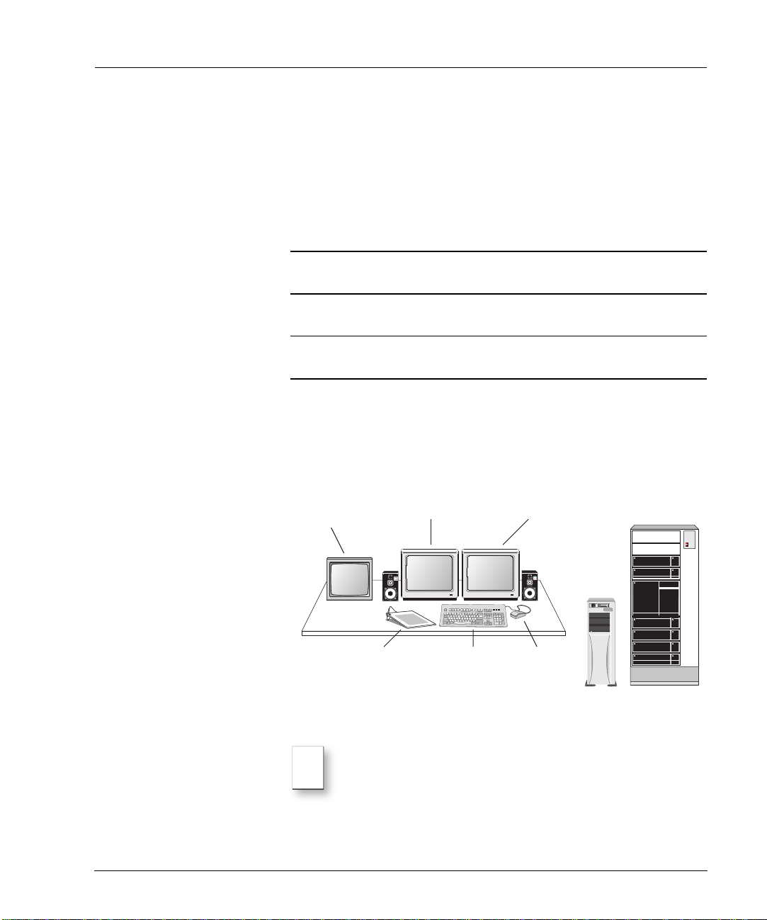
Space Requirements
Depending on the configuration that you purchased, your system includes a
deskside or a rackmount base unit. You can place this unit next to your work
area or in a separate room using an Intergraph Cable Extension kit. The
following illustrates a typical configuration:
NTSC or PAL
video monitor
Video monitor, speakers, VCRs, rack and table are purchased separately.
Note
The video monitor and the computer monitors should be placed at
Left monitor Right monitor
Speakers
MouseKeyboardGraphics tablet
least 12 inches (30cm) apart. Placing them closer together may cause
synchronization interference on the computer monitor.
System Guide 1
Base unit Rack
Page 10

System Guide
The following table lists the dimensions of the major hardware components:
Hardware Component Dimensions (inches) Dimensions (cm)
Base Unit - Deskside Height: 25.8 inches
Depth: 20 inches
Width: 7.9 inches
Base Unit - Rackmount Width: 16.7 inches
Height: 8.8 inches
Depth: 25.3 inches
Monitor Height: 19.5 inches
Width: 20 inches
Depth: 21 inches
Swivel Angle: 90° each left
and right; 13° up; 4° down
WACOM tablet Width: 12 inches
Depth: 12 inches
66 cm
51 cm
21 cm
22 cm
42 cm
64 cm
50 cm
51 cm
53 cm
Swivel Angle: 90° each left
and right; 13° up; 4° down
31 cm
31 cm
Choosing a Location for Your System
Consider the following items when choosing a location for your system:
• For the editing workstation, you need a table (or other surface) that is at
least 60 inches wide by 48 inches deep (150 cm x 120 cm).
• The Intergraph StudioZ base unit comes with 6 feet of cable allowing you
to place it close to your work area. If you want to place it in a separate
room, you must use an Intergraph cable extension kit that contains
keyboard, mouse, and monitor extension cables with an amplifier. To
obtain a cable extension kit, contact your system reseller.
• The base unit must be in a location where air can circulate freely around
it. The side and back panels of the deskside base unit should each have at
least a 3-inch (7.6 cm) clearance. The front and back panels of the
rackmount unit should each have a 36-inch (91.4 cm) clearance.
• External audio and video equipment can reside in the same room as your
workstation or in a separate equipment room.
• Do not expose the system to high levels of dust, smoke, moisture, or high
temperature.
2 System Guide
Page 11

Site Preparation
Package Contents
Your Intergraph StudioZ for SOFTIMAGE|DS system contains the following
hardware, software, and documentation.
Hardware
You should unpack the hardware carefully and verify that you have all the
items that are listed on the packing slip before you start to set up your system.
Make sure that you log the serial number of every device.
Your system contains the following hardware:
Device Device, Cables, and Accessories
Intergraph StudioZ for
SOFTIMAGE|DS Base Unit
Intergraph Multisync 21-inch
Monitors
1 Base Unit
1 S-video cable (3-foot)
1 Flashkey cable (6-inch DB-9 to mini DIN-8)
1 Pipeline cable for machine control (special RS-422)
1 Analog I/O breakout cable with 8 XLR connectors for the
Antex audio card
1 Digital I/O breakout cable for the Antex audio card
2 Base unit supports (for deskside base unit only)
1 Intergraph keyboard
1 Microsoft IntelliMouse
1 3-button mouse
1 Power cable
2 Monitors
2 SVGA monitor cables
2 Power cables
WACOM ArtZII Pen and Tablet 1 Tablet
2 Tablet stands
1 Pen
1 Pen stand
1 RS-232 cable
1 Power transformer cable with AC adapter
1 Registration card
1 9-pin to 25-pin adapter
Software and Documentation
All the software that you receive on disks is also installed on your computer’s
hard drive. You should keep the software disks in a safe place in case you need
to reinstall the software.
System Guide 3
Page 12

System Guide
Your package contains the following:
• The SOFTIMAGE|DS software CD, the software protection key (dongle),
and the complete SOFTIMAGE|DS documentation set which includes the
following information in print and/or online:
Document Description
Release
Notes
System Guide Shows you how to setup your system hardware and perform system
Guided Tour Provides a multimedia overview of the SOFTIMAGE|DS working environment.
Tutorial
Workbook
User’s Guide Describes the interface and details tasks that are specific to each area of
Quick
Reference
Shortcuts Contains a selection of keyboard shortcuts for placing under the top sheet of
Online Help Contains reference information on the parameters contained in property editors
• Windows NT
Describes known problems, and provides workarounds and supplemental
information.
administration tasks.
Contains lessons with specific step-by-step examples.
SOFTIMAGE|DS.
Contains a visual overview of the SOFTIMAGE|DS layouts and tool panels,
editing tips, and the complete list of default keyboard shortcuts.
your graphic tablet.
and dialog boxes, interface elements, and tasks.
®
4.0 Workstation and Windows NT 4.0 Service Pack 3
software and documentation.
• ArtZII software and documentation by WACOM.
• Evolution Series Colorgraphic software and documentation.
• MKS Backup Utilities for Windows NT software and documentation.
• Intergraph DiskAccess software and documentation.
• Integral Flashkey software and documentation.
• Antex Studiocard AV PRO software and documentation.
• StudioZ Central Plus software and documentation.
• StudioZ SDI Board software.
4 System Guide
Page 13

Site Preparation
Reference Documentation
In addition to the software documentation previously listed, the package
contains hardware manuals and other reference material:
• Running Microsoft Windows NT Workstation Version 4.0 by Craig Stinson
and Carl Siechert (Microsoft Press, Redmond, WA).
• Digital Multi-Scan Color Display Operating Instructions.
• WACOM artZII User’s Manual.
• Intergraph StudioZ System Setup.
• StudioZ Late-Breaking News.
Additional Peripherals and Cables
A typical workstation requires that you provide the following additional
peripherals:
Device Description
House Sync The house sync must have the same video format (NTSC or PAL) as
Video Monitor NTSC or PAL
Video Cassette
Recorder (VCR)
A/D Converter An A/D converter is required when using an analog VCR.
Waveform Monitor This device is used for luminance video signal control.
Vector Scope This device is used for chrominance video signal control.
Speakers and Amplifier Analog and/or digital audio equipment connects to XLR connectors.
Cables Video: Use high quality 75-ohm coaxial cables with 75-ohm BNC
Intergraph Cable
Extension Kit
your video equipment and as the project that you create in
SOFTIMAGE|DS.
Digital or Analog.
Analog or digital VCRs connect to the base unit through a RS-422
cable.
Analog devices require A/D converters which are available from your
system reseller.
coaxial connectors.
Audio: Use analog XLR connectors and digital XLR connectors.
This kit contains keyboard, mouse and monitor extension cables with
an amplifier. It is required if you place the base unit more than 6 feet
from the monitor, keyboard, mouse, and WACOM tablet.
The use of any other extension cables may cause signal
degradation.
For more information on optional equipment, contact your system reseller.
System Guide 5
Page 14

System Guide
Inputs and Outputs
The following table describes the system inputs and outputs:
Input/Output Description
Video In Serial Digital In (SDI) via BNC connector.
Video Out SDI out via BNC connector.
Composite out via BNC connector.
Y/C via 4-pin mini DIN (this port is used for the software video
interface).
Analog Audio In 4 female XLR connectors. Line input 600 ohms.
Analog Audio Out 4 male XLR connectors. Line output 600 ohms.
Digital Audio In Female XLR connector; AES/EBU or S/PDIF.
Digital Audio Out Male XLR connector; AES/EBU or S/PDIF.
Sync In BNC connector.
RS-232 Remote DB-9 connector.Connects to the Pipeline cable for converting RS-
232 to RS-422. Use only the supplied cable.
To take full advantage of the high quality serial digital interface (SDI)
capability of your workstation, you should connect the digital devices directly
to the SDI ports on the Intergraph StudioZ card and to the AES/EBU - S/PDIF
output from the Antex card.
Avoid using adapters because they may cause signal degradation. If you must
use them, use only high-quality, tight-fitting adapters.
For detailed instructions on connecting your system, see Connecting the
Hardware on page 7.
6 System Guide
Page 15
Connecting the Hardware
This section provides step-by-step instructions for connecting a the base unit
to the peripheral devices in a standard configuration. It covers both analog
and digital setups. A complete cabling diagram is also included in the
Appendix on page 45.
The cards are installed and configured for the SOFTIMAGE|DS environment.
You should not remove or modify these cards.
Connecting the Hardware
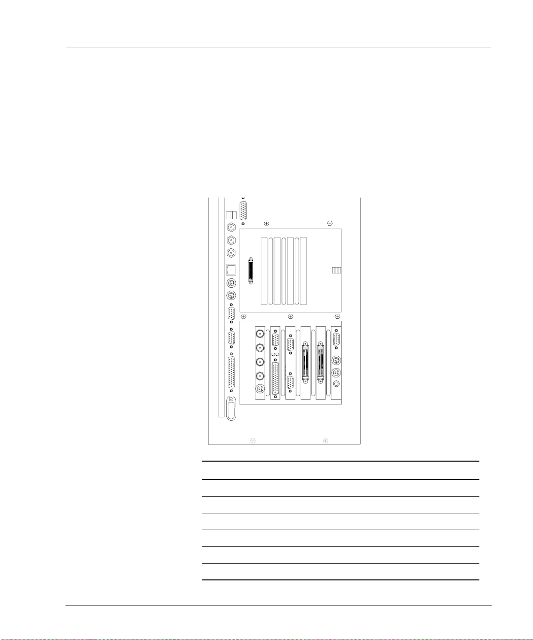
Back Panel Overview
On the back panel of your base unit, six cards are installed and configured for
the SOFTIMAGE|DS environment.
REF
IN
SDI
OUT
SDI
IN
COMP
OUT
Y
/C
123456
Deskside Base Unit
Slot Function
Card
1 Video in a Window Integral Flashkey
2 Array Controller Adaptec 1
3 Array Controller Adaptec 2
4 Graphic Output Colorgraphic Evolution 2
5 Audio I/O Antex StudioCard
6 SDI Video I/O Intergraph StudioZ
System Guide 7
Page 16

System Guide
Note
Video in a Window Card
The Video in a Window card is the Flashkey by Integral Technologies. It lets
you display real-time video in the SOFTIMAGE|DS viewer on your computer
monitor.
Array Controllers
The array controllers are two Adaptec 2940 SCSI controllers. Each one
controls data I/O for two of the four Ultra Wide SCSI video storage disks.
Graphics Card
The graphics card is an Evolution 2 graphics adapter from Colorgraphic
Communications. It controls the dual-screen VGA output to your computer
monitor.
Audio Card
The audio card is an Antex Studiocard. It receives and transmits audio
signals.The Antex Studiocard supports four independent balanced analog I/O
(+4 dBu) and AES/EBU or S/PDIF digital I/O.
Serial Digital Interface (SDI) Card
The SDI card is the Intergraph StudioZ card that handles video input and
output of both compressed and uncompressed Serial Digital Video data. The
Intergraph StudioZ combines Joint Photographic Experts Group (JPEG)
Compression/Decompression circuitry with SDI on a single PCI board.
In the rackmount base unit, the slot allocation is identical but the
unit is horizontal.
For more details on the cards, refer to the accompanying vendor
documentation.
To prevent damage that may be caused by static electricity, do the
!
following before making any connections:
• Turn the power switch off on all the devices.
• Connect all the devices to a power source.
• Touch the metal casing of the device.
Connecting to a Power Source
8 System Guide
The Intergraph base unit and monitor support both 110V/60 Hz and
220V/50 Hz power. The WACOM tablet comes with a single voltage AC power
adapter. If it does not match your AC power source, contact your system
reseller.
The base unit, monitors, and WACOM tablet each require a separate AC
power source. To supply your SOFTIMAGE|DS workstation as well as
Page 17
Connecting the Hardware
additional peripheral devices, you must have access to four AC outlets with
two 15 Amp circuits (or 7.5 Amp in Europe).
To connect the workstation to a power source
1. For every device, make sure that the voltage of the power source matches
the voltage requirements of the device.
2. Make sure that power to all the devices is turned off.
3. Connect the base unit, the monitor(s), the WACOM tablet, and any other
peripheral devices to a power source.
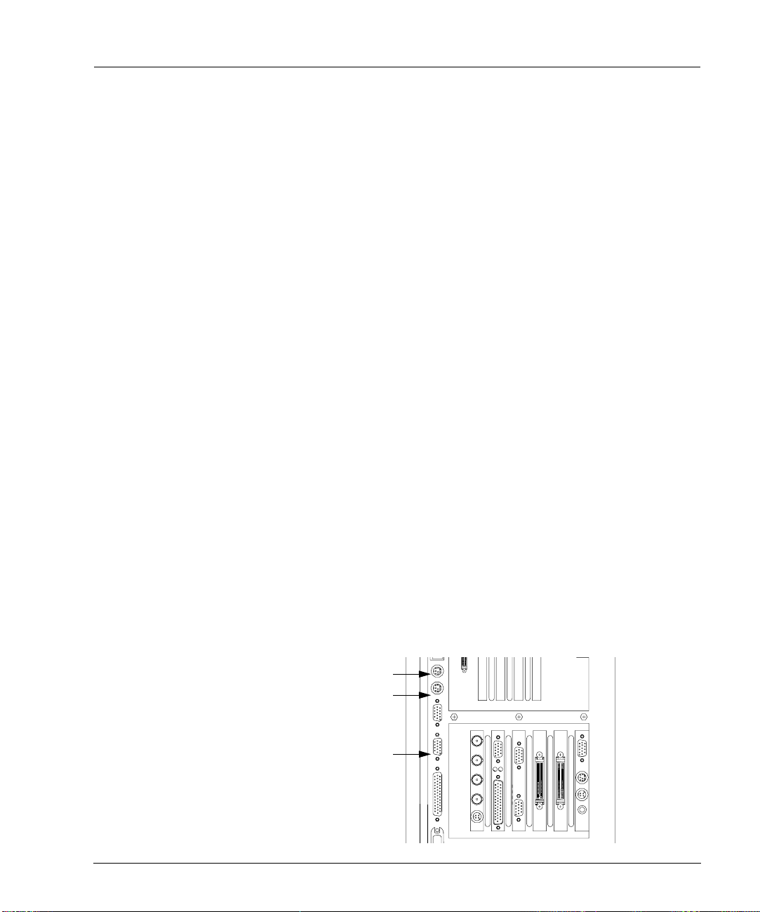
Connecting the Keyboard, Mouse and WACOM tablet
The keyboard and the mouse come with attached cables for connecting them
to the back panel. The WACOM tablet comes with a power transformer and a
DB-9 cable.
To connect the keyboard and the mouse
1. Connect the keyboard to the top mini-DIN jack in the deskside base unit.
If you have a rackmount base-unit, connect the keyboard to the left-hand
mini-DIN jack.
2. Connect the Microsoft IntelliMouse to the bottom mini-DIN jack in the
deskside base unit. If you have a rackmount base-unit, connect the mouse
to the right-hand mini-DIN jack.
To connect the WACOM tablet
1. Connect the AC power transformer to the tablet DB-9 cable.
2. Connect one end of the DB-9 cable to the COM 2 port on the back panel
and connect the other end to the tablet.
3. Before plugging in the AC power transformer, check that the input voltage
on the power adapter matches the voltage of your power outlet.
4. Connect the power adapter to the AC outlet.
For more information on connecting the WACOM tablet, refer to the
accompanying vendor documentation.
Keyboard
Mouse
WACOM tablet
REF
SDI
OUT
IN
SDI
COMP
OUT
Y
/C
System Guide 9
Page 18
System Guide
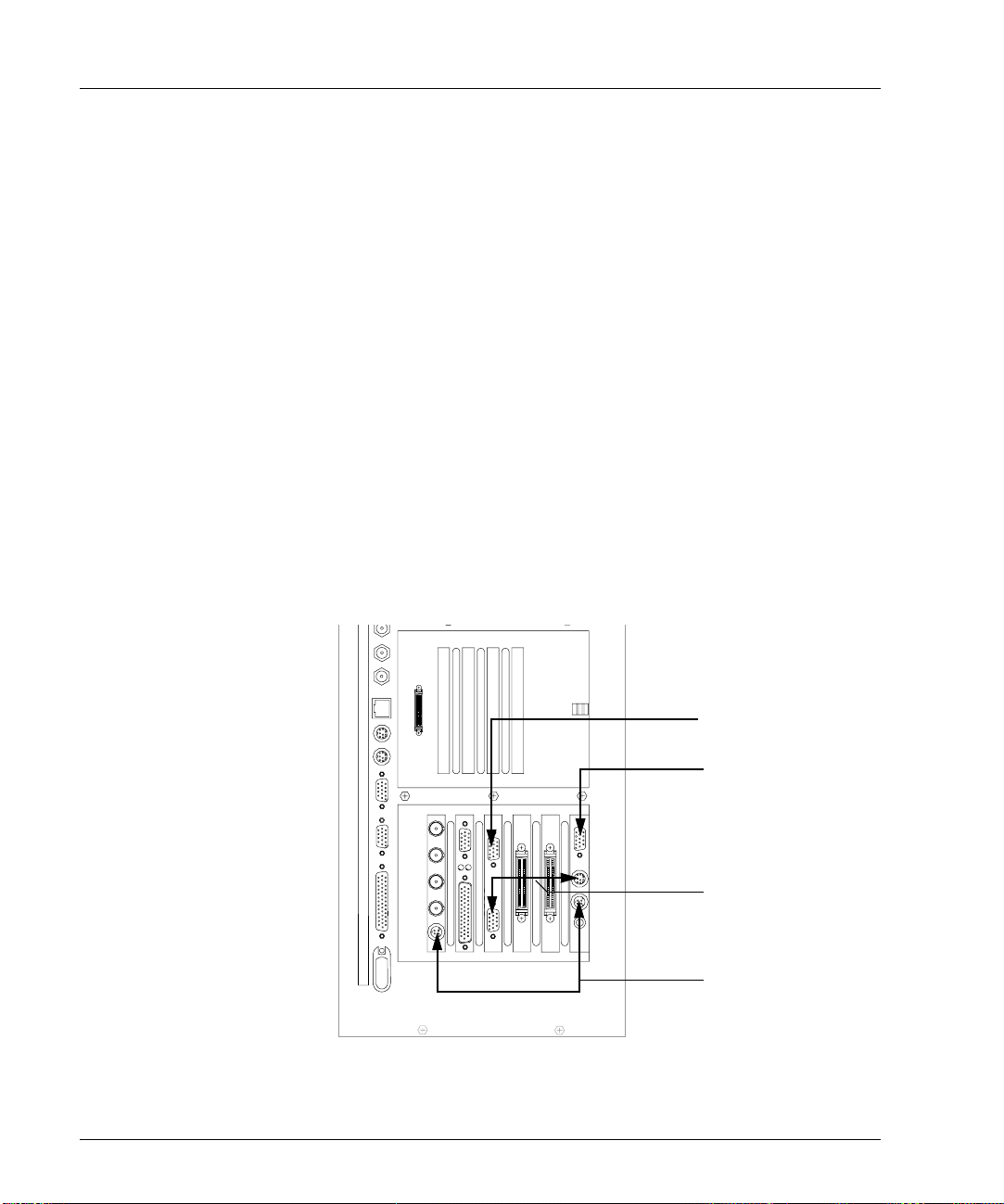
Connecting the Computer Monitors
Your workstation comes with two identical Intergraph monitors for
displaying the SOFTIMAGE|DS editing environment. You should place the
monitors side by side in your work area.
Each monitor comes with the following cables:
• VGA cable
• Power cable
To connect the monitors
1. If you have not already done so, turn off the power switch to the monitors
and the base unit and connect them to a power source.
2. Connect the monitor which is on the right side to the Video in a Window
card using the VGA cable supplied.
3. Connect the monitor which is on the left side to the top port on the
graphic card using the VGA cable supplied.
4. Connect one end of the Flashkey cable to the second port from the top of
the Video in a Window card and connect the other end to the lower port
of the graphic card.
5. Connect one end of the S-Video cable to the Y/C port of the Intergraph
StudioZ card and connect the other end to port that is second from the
bottom on the Video in a Window card.
REF
SDI
OUT
SDI
IN
COMP
OUT
Y
/C
10 System Guide
VGA Cable
To Left Monitor
VGA Cable
To Right Monitor
Flashkey Cable
S-Video Cable
Page 19

Connecting the Hardware
Connecting Peripheral Devices
Peripheral devices such as VCRs and DATs connected to your workstation
allow you to capture and output video and audio material. You can control
this equipment remotely with SOFTIMAGE|DS.
Video Connections
Your system can contain digital and/or analog VCRs and video monitors. If
you use an analog video monitor, it is connected directly to the Intergraph
StudioZ card, and the composite video signal that it receives is of a lower
quality.
Note
When connecting the devices, make sure that all video outputs are
terminated by the video device to which they are connected. Also
ensure that no device is connected to a power source.
To connect a system with digital devices
1. Connect the SDI In on the Intergraph StudioZ card to the SDI Out on the
VCR .
2. Connect SDI Out on the Intergraph StudioZ card to the SDI In of the
VCR .
3. Connect the SDI loop through on the video monitor to SDI In on the
VCR .
4. Set the VCR transport switch to Remote.
5. Connect the COM 1 port on your base unit to the REMOTE IN port on
the VCR using the pipeline cable supplied. You should not substitute the
pipeline cable with any other cable, but you can extend the RS422 end
with other cables if required.
6. Connect the Ref In port on the Intergraph StudioZ card to the House Sync Ref Out.
Ref
House Sync
Digital VCR
Oscilloscope
System Guide 11
IN
SDI
OUT
SDI
IN
COMP
OUT
Y
/C
Digital
Video
Monitor
Video connections for digital peripheral devices
Page 20

System Guide
To connect a system with analog devices
1. Connect the SDI In on the Intergraph StudioZ card to the Video Out on
the analog VCR via a A/D converter.
2. Connect SDI Out on the Intergraph StudioZ card to the Video In on the
analog VCR via a D/A converter.
3. Connect Comp Out port on the Intergraph StudioZ card to the Video in
on the analog video monitor.
4. Set the VCR transport switch to Remote.
5. Connect the COM 1 port on your base unit to the REMOTE IN port on
the VCR using the pipeline cable supplied.You should not substitute the
pipeline cable with any other cable but, you can extend the RS422 end
with other cables if required.
6. Connect the Ref In on the Intergraph StudioZ card to the House Sync.
House Sync
ADC
Analog VCR
DAC
Oscilloscope
Ref
SDI
OUT
SDI
COMP
OUT
Y
/C
Analog
Video
Monitor
Video connections for analog peripheral devices
12 System Guide
Page 21

Connecting the Hardware
s
Audio Connections
You can connect both digital and analog audio devices to your system’s Antex
StudioCard AV PRO. When you capture audio, SOFTIMAGE|DS enables the
input that you specify.
To connect audio cables
1. Attach the Antex digital I/O cable to the upper (DB-15) port on the audio
card and tighten the locking screws.
2. Attach the Antex analog I/O cable to the lower (DB-25) port on the audio
card and tighten the locking screws.
3. Referring to the white tags on the Antex cables, connect your external
audio equipment to the appropriate analog and digital connectors.
Digital breakout cable
Analog cable with 8 XLR connector
System Guide 13
Page 22

System Guide
Attaching the Software Protection Key
The software protection key, also called a dongle, provides copy protection for
the software that is installed on your system. It is attached to your system’s
parallel port. SOFTIMAGE|DS can start only if the software protection key
identification number matches the information in the license file that is
already installed on your computer’s hard drive.
This licensing scheme is managed by the FLEXlm
®
software which is already
installed on your system. For more information on the license software, refer
to Installing the License File on page 36 and refer to the FLEXlm online help.
• To attach the software protection key, attach it to the base unit’s parallel
port (LPT1)
LPT1
Moving the System
It is important to follow the correct procedure when moving the system to a
different location.
Do not move the base unit without first turning off the power or else
!
internal components may be damaged.
To move the system
1. Shut down your computer.
2. Turn off power to all the devices.
3. Disconnect all the devices.
4. Disconnect the power cables.
5. Move the components carefully.
6. Make sure the new location meets site requirements (see Site Requirements
on page 1).
7. Reconnect the equipment as described in this chapter (see Connecting the
Hardware on page 7).
14 System Guide
Page 23

Starting SOFTIMAGE|DS
Starting SOFTIMAGE|DS
SOFTIMAGE|DS has already been installed on your computer’s hard drive. To
start it, follow these steps:
To start SOFTIMAGE|DS
1. Turn on all the devices.
2. Log on to Windows NT.
When you log on for the first time, you can use a blank password. For
information on changing your password, refer to Managing User Accounts
on page 22.
3. Click the Start > Programs > SOFTIMAGE|DS > SOFTIMAGE|DS.
The Project dialog box is displayed.
4. Click New Project.
The New Project dialog box is displayed.
5. In the Project Name box, enter a name for your new project.
The SOFTIMAGE|DS Editing Layout is displayed by default.
You can now capture material and build your project. To find out the best
approach to learning SOFTIMAGE|DS, refer to the SOFTIMAGE|DS Road
Map.
Tip
You should create separate Windows NT user accounts so that each
SOFTIMAGE|DS user can save their own project preferences. See
Managing User Accounts on page 22.
System Guide 15
Page 24

System Guide
System Hardware Overview
Intergraph StudioZ for SOFTIMAGE|DS
Your Intergraph StudioZ workstation provides a comprehensive set of
optimized hardware features that allow you to achieve high-quality results
with the SOFTIMAGE|DS software. This section provides an overview of the
hardware. For details, see the vendor documentation accompanying each
device. See Connecting the Hardware on page 7 for details on cable
connections.
Striped Disk Set
System Disk - partitioned
R
Audio out
FlashKey Card
Adaptec 2940
SCSI Controller Card
Adaptec 2940
SCSI Controller Card
Video out
Colorgraphic
Evolution 2 Video Card
Antex StudioCard
Video out
Video out
Audio in/out
Right Monitor
Left Monitor
L
COM 1
COM 2
Adaptec 7880
SCSI Controller
(on riser card)
Clock
Sync
VTR Control
Hardware components of the Intergraph StudioZ and associated peripheral devices
16 System Guide
Video out
Intergraph StudioZ SDI
Card
Genlock (Ref In)
WACOM Tablet
VTR
Video in/out
Page 25

System Hardware Overview
Intergraph StudioZ SDI and Associated cards
The following table describes the function of each card installed in the
Intergraph StudioZ. Cards are installed in all Peripheral Component
Interconnect (PCI) slots. Slots 5 and 6 are primary PCI sockets (PCI0). The
rest of the slots are secondary PCI (PCI1). See the vendor documentation for
details on card specifications and configuration.
Slot Card Function
1 Video in a Window card Processes input from Intergraph StudioZ and
2 Adaptec 2940 SCSI Controller Controls data I/O for two of four Ultra Wide SCSI
3 Adaptec 2940 SCSI Controller Controls data I/O for two of four Ultra Wide SCSI
4 Colorgraphic Evolution 2 Dual monitor graphics card outputs video data to
5 Antex Audio StudioCard Processes audio and clock sync signal I/O for
6 Intergraph StudioZ SDI Processes video capture/playback I/O for VCR
Colorgraphic card and outputs video signal to
right monitor with Video in a Window.
video storage disks.
video storage disks.
Video in a Window card and to left monitor.
VCR (Video Cassette Recorder) and ports audio
to optional devices, such as stereo speakers.
and ports video to FlashKey card; also provides
Genlock capability (Ref In).
System Guide 17
Page 26

System Guide
Signal Flow
The following provides an overview of the signal flow in the system’s two
modes. The SOFTIMAGE|DS software controls the process and specifies the
type of video compression used.
Capture
Capture mode allows you to use SOFTIMAGE|DS to capture or play back
video and audio from the VCR.
• The video output of the VCR goes to the Intergraph StudioZ card.
• The audio output of the VCR goes to the Antex card and then to the audio
storage on disk.
• The clock sync signal from the Intergraph StudioZ card goes to the Antex
card.
• The video output from the Intergraph StudioZ card goes to the video
storage on disk.
• The S-video output of the Intergraph StudioZ card goes to the FlashKey
card and then to the right monitor, where it displays as video in a window.
• The control signal from the COM 1 port goes to the VCR to control device
operation.
• The sync signal from the house sync goes to the Intergraph StudioZ card.
Record
Record mode allows you to use SOFTIMAGE|DS to record video on the VCR.
• The video stored on disk goes to the Intergraph StudioZ card, and then
goes to the VCR.
• The audio stored on disk goes to the Antex card, and then goes to the
VCR .
• The clock sync signal goes from the Intergraph StudioZ card to the Antex
card.
• The S-video output of the Studio Z card goes to the FlashKey card and
then to the right monitor, where it displays as video in a window.
• The control signal from the COM 1 port goes to the VCR to control device
operation.
• The sync signal from the house sync goes to the Intergraph StudioZ card.
18 System Guide
Page 27

System Hardware Overview
SCSI Disk Subsystem
In a standard configuration, one 9-GB 7,200-RPM Ultra-Wide SCSI disk
drive and four identical 9-GB 10,000-RPM Ultra-Wide SCSI disk drives are
installed in the external and internal drive bays of the Intergraph StudioZ. No
bays are available to install additional drives. The 9-GB 7,200-RPM system
disk drive is formatted with three partitions for storage of operating system
files, project files, and audio files. Four 9-GB 10,000-RPM disk drives are
formatted as a striped set for video file storage.
Disk striping is a hardware capability that speeds up data I/O from disk
storage. The computer divides the data into pieces and spreads the pieces
across the disks in the striped set. Because the computer transfers data to
multiple drives in chunks smaller than it would transfer to a single drive, data
transfer is accelerated.
Each of the Adaptec 2940 SCSI Controller cards handle data I/O for two video
storage drives. The Adaptec 7880 SCSI Controller, located inside the
Intergraph StudioZ, handles data I/O for the system disk drive. The Adaptec
controllers provide a maximum theoretical sustained data transfer rate of 40
MB per second. With disk striping, this rate is increased to about 50 MB per
second.
The following table summarizes disk drive information. Note that the CDROM is assigned drive letter G.
Drive Label Size Function Format
C:\ System 2 GB partition Stores operating
system software
E:\ Audio Storage 4 GB partition of C:\ Stores audio files NT File System
File Allocation
Table (FAT)
(NTFS)
System Specifications
F:\ Projects 3 GB partition of C:\ Stores project-
D:\ Video Storage 4 each 9 GB
(striped)
related files
Stores video files NTFS
NTFS
For details on the Intergraph StudioZ hardware configuration, see
Intergraph’s online System Reference document provided on disk in the
WIN32APP\SYSREF directory.
System Guide 19
Page 28

System Guide
System Administration
To perform system administration tasks, you need to be familiar with the
directories and files installed on your system. You should also have sufficient
working knowledge of Windows NT to manage user accounts and perform
disk performance tests.
Managing projects and project media is performed in SOFTIMAGE|DS. For
more information on these tasks, refer to the SOFTIMAGE|DS User’s Guide.
Directories Installed on Your System
When you install SOFTIMAGE|DS, five directories are created to hold various
system files, project files, as well as media and cache files.
These are the directories that are created:
Directory Description
SOFTIMAGE|DS Contains the files required to run SOFTIMAGE|DS.
DS Projects Contains the projects, sequences, and clips that you create in
DS Presets Contains cusomized effects that you can use in SOFTIMAGE|DS
Video Storage Contains the video media and cache files that you capture and bring
Audio Storage Contains the audio media and cache files that you capture and bring
SOFTIMAGE|DS.
when creating graphics, transitions, compositing, etc.
into SOFTIMAGE|DS.
into SOFTIMAGE|DS.
The SOFTIMAGE|DS Directory
This directory contains the SOFTIMAGE|DS executable as well as the various
.dll files required by the software. You should not move or modify these files
in any way. The SOFTIMAGE|DS directory also contains the following
folders:
• Guided Tour
This folder contains all the files required to run
SOFTIMAGE|DS Guided Tour
which is a multimedia presentation that helps you become familiar with
SOFTIMAGE|DS.
• Online Help
This folder contains all the files required to use the online help. Online
help provides reference information on property editors, dialog boxes,
parameters, interface elements, and tasks.
• Papers
This folder contains bitmaps that you can use to add texture to paint
strokes, shapes, and titles that you create in SOFTIMAGE|DS.
•Setup
This folder contains all the files required by the setup program which
allows you to remove SOFTIMAGE|DS or to add optional software
components.
20 System Guide
Page 29

System Administration
The DS Projects Directory
The DS Projects directory contains the projects that you create with
SOFTIMAGE|DS. Each time you create a new project, you are prompted to
select a location for the project folder. Although you may store project folders
anywhere on a local disk, it is easier to manage projects if they are all stored in
the DS Projects directory.
The project folder contains the clips and sequences associated with a project.
Each project folder also contains a system folder.
You should not move, delete, or modify the contents of the system
!
folder. The system folder should also be hidden. To hide specific file
types, choose Options from the View menu in Windows Explorer.
The system folder contains the following information:
• Source models
Source models are data structures that allow SOFTIMAGE|DS to manage
the relationship between clips, sequences and their associated media. Each
time you capture media from a new source, SOFTIMAGE|DS creates a
corresponding source model. The source model tracks the timespan,
quality, and location of the different media files captured from that
source. When you play back a clip from that source, SOFTIMAGE|DS
consults the appropriate source model to locate the media.
• dsprojectinfo
The dsprojectinfo file contains information about the project format and
other project preference settings. For more information on project
preferences, refer to the SOFTIMAGE|DS User’s Guide.
The Presets Directory
The Preset directory contains presets which you can use to define effects,
transitions, graphics tools, etc. When you create your own presets in
SOFTIMAGE|DS and they are stored in this directory.
The Video Storage Directory
The Video Storage directory contains individual folders for each project. Each
folder contains the video media and cache files for that project. Each folder’s
name is generated by the software and is based on a unique identification
string (called a GUID) that identifies each project.
The Audio Storage Directory
Similar to the Video Storage Directory, the Audio Storage directory contains
individual folders for each project. Each folder contains the audio media files
for that project.
System Guide 21
Page 30

System Guide
You should not delete audio or video media files or folders from
!
your Windows NT desktop. If you want to delete a media file, use
the purge command in SOFTIMAGE|DS. For information on
deleting clips and/or purging media, refer to the SOFTIMAGE|DS
User’s Guide.
Managing User Accounts
SOFTIMAGE|DS makes full use of the Windows NT operating system. This
includes multiple user accounts with security and preferences set on an
individual basis.
How SOFTIMAGE|DS Uses User Accounts
When you log on to a Windows NT workstation, you are accessing an
environment associated with your user name. When you set any personal or
project preferences while logged on, SOFTIMAGE|DS saves them to your user
profile. For example, when you customize the SOFTIMAGE|DS desktop the
layouts that you create are saved with your user name. The next time you log
on to that machine, it recalls your previous settings.
Managing User Accounts
When you first receive your SOFTIMAGE|DS system, Windows NT is
installed and an administrator account is set up with a blank password.
You can change your password, create and modify accounts by accessing the
Windows NT User Manager. The User Manager lets you define security
features such as permissions, rights, accounts, user groups, and audit policies.
For more information on Managing User accounts, refer to Running Microsoft
Windows NT Workstation Version 4.0 which is include in your system package.
22 System Guide
Page 31

System Administration
To create a user account
1. From the Windows NT desktop, choose Start > Programs >
Administrative Tools > User Manager.
The User Manager dialog box is displayed.
2. Choose User > New User and enter the new user information in the dialog
box.
After you click OK, the new user is displayed in the User Manager dialog
box.
To modify an account
1. From the Windows NT desktop, select Start > Programs > Administrative
Tools > User Manager.
The User Manager dialog box is displayed.
2. Select the user name that you want to modify, or select Administrator to
modify the administrator’s account.
3. Choose User > Properties, and enter a new password.
Tip
You can also press CTRL+ALT+DEL and select Change Password.
4. Choose Policies > Accounts and select the desired options.
5. Choose Policies > Audit and set the audit policy for the selected account.
6. Choose Options and select the options from the menu.
To delete an account
1. In the User Manager dialog box, select an account.
2. Choose User > Delete.
After you confirm, the selected account is deleted.
System Guide 23
Page 32

System Guide
Rebuilding the System
When you first receive your Intergraph StudioZ for SOFTIMAGE|DS, all the
software you need to run SOFTIMAGE|DS is already installed and tested. You
should not remove or modify the installed software.
Your system is finely tuned and the approved configuration must be
maintained. This section is included in case you need to reinstall or re
configure certain components, or re-install SOFTIMAGE|DS.
For details on the hardware drivers, refer to the accompanying vendor
documentation.
Installing the Graphics Card Driver
Your system’s graphics card is an Evolution 2 Colorgraphics adapter from
Colorgraphic Communications. This card requires that you install and
configure the Evolution 2 driver for Windows NT.
To install the graphics card driver
1. In the Windows NT Control Panel, double-click the Display icon.
2. In the Display Properties dialog box, select the Settings tab.
3. In the Settings page that is displayed, click the Display Type button.
4. In the Display Type dialog box that is displayed, click the Change button.
5. In the Change Display dialog box, click the Have Disk button.
The Install From Disk dialog box is displayed.
6. Insert the disk containing the Colorgraphic Evolution 2 driver into your
computer’s disk drive.
7. In the Install From Disk dialog box, click the Browse button and open the
folder that contains the Colorgraphic Evolution 2 driver for Windows NT.
8. Select the file with an .inf file extension and click the Open button.
9. In the Install From Disk dialog box, click OK.
The Change Display dialog box is displayed again.
10. In the Change Display dialog box, click OK.
A Third-party Drivers warning message is displayed.
11. Click YES.
The driver is installed. The Installing Driver warning message is displayed,
indicating that the system will restart.
12. Click OK.
When the system restarts, the Display Properties dialog box is displayed,
as well as the following warning :
24 System Guide
Page 33

Rebuilding the System
13. Click OK, and adjust the settings in the Display Properties dialog box as
described in the following task.
To adjust the display settings
1. After you complete the Colorgraphic Evolution 2 driver installation, the
system restarts and the Display Properties dialog box is displayed.
2. In the Display Properties dialog box, select the Settings tab.
The Settings page is displayed.
3. Adjust the following settings:
• From the Color Palette list box, select 16777216 Colors.
• Adjust the Desktop Area slider to 1280 by 1024 pixels.
• From the Font Size list box, select Small Fonts.
• From the Refresh Frequency list box, select 60 Hertz.
4. Click the Te st button.
You are prompted to confirm, and the test is started.
System Guide 25
Page 34

System Guide
5. When the test is complete, click Ye s . If you did not see the test bitmap
properly, verify the settings and repeat the test. If the problem persists,
contact your system reseller.
6. Click OK to close the Display Settings dialog box.
The display is configured.
Installing the Audio Driver
Before installing the Antex driver, you must remove any previous versions.
Once the driver is installed, you must set the Windows NT multimedia
properties, and set the Antex mixer. It is very important that you set the
sample clock in the Antex mixer.
Do not stop the Antex driver before removing it. If you do, you will
!
have to log off and then log on and restart the Antex driver.
To remove the Antex driver
1. In the Windows NT Control Panel, double-click the Multimedia icon.
2. In the Multimedia property editor, select the Devices tab.
3. Click the plus (+) sign next to Audio Devices to expand the folder.
4. Select Audio for Antex Digital Audio Driver and click Remove.
5. In the Windows Explorer, open the C:\Winnt\system32\Drivers folder and
delete the AntexWAV.sys file.
6. Delete the C:\Antex folder.
26 System Guide
Page 35

Rebuilding the System
To install the Antex driver
1. Insert the disk containing the Antex driver into your computer’s disk
drive.
2. Locate the folder containing the Antex files and double-click the Setup.exe
file.
3. In the Welcome to the Antex Driver Setup dialog box, click Continue.
4. Accept the default path C:\Antex.
The Antex Driver is installed and started.
To set the multimedia properties
1. In the Windows NT Control Panel, double-click the Multimedia icon.
2. Select the Audio tab and set the properties as follows:
3. In the Audio page, click the Customize button in the Recording box.
System Guide 27
Page 36

System Guide
4. In the Customize dialog box, select PCM in the Format list box.
5. In the Attributes list box, select 44.100 kHz, 16-Bit, Stereo 172 Kb/sec.
6. In the Name list box, click Save As and enter DS Settings.
The audio settings are saved in the DS Settings folder.
To set the Antex mixer
1. On the Windows NT desktop, click Start > Programs > Antex Mixer.
The Antex Mixer dialog box is displayed.
2. Choose Mixer > Lines and select both Adapter, and Digital Out from the
list.
Selecting Digital Out enables MIDI output. Selecting Adapter ensures that
the Sample Clock is displayed when you close the Lines dialog box.
3. In the Antex Mixer dialog box, click the Line In button to set the Sample
Clock for the Analog input.
4. In the Sample Clock box select the following analog settings:
•Set Source to Internal
•Set Reference to 27MHz
• Set the Sample Rate to 44100
5. Click the Digital In button to set the Sample Clock for Digital input.
Note
If a Not Valid message is displayed over the Digital In box, it
means that the Antex digital I/O cable is not receiving a valid
digital signal and you should verify the audio connections.
6. In the Sample Clock box, select the following digital settings:
•Set Source to Digital
•Set Reference to Auto
• Set the Sample Rate to 48000 (or 44100)
28 System Guide
Antex Mixer
Page 37

Rebuilding the System
7. From the Scene menu, choose Save As and save the Mixer file as DS Mixer.
Testing the Antex Hardware
Once you have installed the audio driver, you should run the Antex demo to
test the Antex hardware. You should also verify that the MIDI output is
enabled.
To run the Antex demo
1. From the Windows NT desktop, choose Start > Programs > Antex Demo
Programs.
2. Select Antex Demo from the list.
3. In the Antex Demo dialog box, click File.
4. In the WinNT\Media folder, select Windows NT logon sound.
5. In the Antex Demo dialog box, click Play.
The logon sound is played. If this test fails, verify your hardware
connections and then repeat the driver installation. If the problem
persists, contact your system reseller.
To verify that MIDI output is enabled
1. In the Windows NT Control Panel, double-click the Multimedia icon.
2. In the Multimedia Properties dialog box, select the MIDI panel.
3. Verify that Antex is displayed in the MIDI output list.
System Guide 29
Page 38

System Guide
Installing the SDI Driver
The Intergraph StudioZ SDI driver controls the Intergraph StudioZ card that
lets you capture, edit, and play back real-time video and animation on your
Intergraph workstation.
To install the Intergraph StudioZ driver
1. Insert the disk containing the Intergraph StudioZ driver into your
computer’s disk drive.
2. Locate the folder containing the Intergraph StudioZ files and double-click
the Setup.exe file.
The Welcome dialog box is displayed.
3. Click Next.
The dialog box displays the Destination folder C:\Program
Files\Intergraph\StudioZ Driver.
4. Click Next to accept the default destination folder.
5. You are prompted to read the Read Me file. You can read this file now or
come back to it at a later date.
The Intergraph StudioZ driver setup is complete.
To start the Intergraph StudioZ driver
1. In the Windows NT control panel, double-click the Devices icon.
2. Select Intergraph StudioZ from the list.
3. Make sure that Startup is set to System.
If it is not, press the Startup button and select System as the Startup type.
4. Press the Start button.
The Intergraph StudioZ driver is started.
To configure the Intergraph StudioZ driver
1. In the Windows NT control panel, double-click the Multemedia icon.
2. In the Devices page, locate the Video Compression Codex folder. If
required, click on the plus sign next to the folder to expand it.
3. In the Video Compression Codex folder, select the Intergraph StudioZ
Driver.
4. Click the Properties button.
30 System Guide
Page 39

Rebuilding the System
5. In the Properties dialog box, click the Settings button.
The configuration dialog is displayed.
6. In the Genlock group box, select Reference Enable option.
Your House Sync is used for synchronization. SOFTIMAGE|DS overrides
all the other settings in this dialog box.
The configuration is effective after you start the Intergraph StudioZ driver.
System Guide 31
Page 40

System Guide
Installing the Video in a Window Driver
Installing the Mouse Driver
The Video in a Window card controls real-time video in a computer monitor.
In your system, this card is the Integral Technologies Flashkey card.
To install the Integral Flashkey card driver
1. Insert the disk containing the Integral Flashkey driver in your computer’s
disk drive.
2. Locate the folder that contains the Integral Flashkey files and double-click
the Setup.exe file.
The setup is completed and you are asked if you want to restart the system.
3. Do not restart the system when prompted.
4. In the folder that contains the Integral Flashkey files, double-click the
Install_ini.bat file.
The Flashkey driver is installed.
5. Restart the computer.
To take advantage of all the functions on your Microsoft IntelliMouse, you
must install the IntelliMouse driver.
To install the IntelliMouse driver
1. Insert the disk containing the IntelliMouse driver into your computer’s
disk drive.
2. Open the folder that contains the IntelliMouse driver.
3. Double-click the Setup.exe file.
All required files are copied.
4. In the Microsoft IntelliPoint 2 Setup dialog box, click Next.
5. In the next dialog box that is displayed, enter your name and company in
the appropriate text boxes and click Next.
6. The next dialog box displays your name and company information, as well
as the product identification number. You should write down this number
for future reference, and then click Next.
7. When prompted to choose a location for the driver, click Next to accept
the default folder.
8. Click Finish to complete the installation.
9. Click Close to exit the setup program.
32 System Guide
Page 41

Rebuilding the System
10. When the installation is complete, do one of the following:
• If you want to install the WACOM driver next, press the Return to
Windows button.
After you install the WACOM driver, restart Windows NT and the
Microsoft IntelliPoint setup will be completed.
• If you do not want to install other drivers, click Restart Windows to
complete the installation of the mouse driver.
Installing the WACOM Driver
The WACOM driver controls the WACOM pen and tablet. After you install
the WACOM driver, you can use the default configuration settings, or you can
customize the pen and tablet according to the way you like to work.
For example, if you are working with a pressure-sensitive brush in
SOFTIMAGE|DS, you may want to adjust the pen tip sensitivity to fine tune
the feel of the pen tip. Or, if you are using SOFTIMAGE|DS paint tools to
trace the shape of an object on the tablet, you must configure the tablet so that
the resulting graphic object is proportionally correct.
To install the WACOM driver
1. Insert the disk containing the WACOM driver into your computer’s disk
drive.
2. Locate the folder containing the WACOM files and double-click the
Setup.exe file.
3. Accept all the defaults.
4. When the setup is complete, shut down and restart your computer.
5. To test the WACOM driver, drag the pen on the tablet.
On the monitor, the pointer should follow the pen movement.
System Guide 33
Page 42

System Guide
To configure the WACOM driver
1. In the Windows NT control panel, double-click the WACO M Tabl et icon.
The WACOM tablet driver is displayed.
2. Click the Settings button.
The Settings menu is displayed. It contains a list of icons that let you
change the pen and tablet settings.
3. If you want to adjust the pen switch functions, click the Pen icon, and
adjust the settings in the Pen setup box.
4. If you want to adjust the pen pressure sensitivity click the Tip Pressure
icon and adjust the settings in the Tip Pressure setup box.
34 System Guide
Page 43

Rebuilding the System
Adjust amount of pressure
needed to click
Adjust the feel of the pen
tip to normal, soft or firm
5. If you want to specify the screen-tablet relationship click the Scaling icon,
and adjust the settings in the Scaling setup box.
Define tablet area to be
mapped to screen
Define screen area to be mapped
to specified tablet area
Change constraints of tablet
to screen relationship
For more information on customizing your WACOM graphic tools, refer to
the WACOM documentation.
System Guide 35
Page 44

System Guide
Installing the License File
For SOFTIMAGE|DS to start, your system needs a software protection key
(dongle) and a license file. The information on the software protection key is
compared with information in the license file; if they match, SOFTIMAGE|DS
can start.
The Software Protection Key
Before you can install the license server, the software protection key must be
attached to your computer, the corresponding port must be active, and the
software protection key driver must be installed.
• To attach the software protection key, attach the software protection key to
the base unit’s parallel port (LPT1). Refer to the illustration on page 14.
To make sure the port is active
1. In the Windows NT Control Panel, double-click the Devices icon.
2. In the Devices dialog box, locate Parallel from the list.
3. Verify that the Status is Started. If it is not started, click Startup.
4. Select the Automatic check box
5. Shut down and restart the computer.
To install the software protection key driver
1. Insert the SOFTIMAGE|DS CD into the CD-ROM drive.
2. From the SOFTIMAGE|DS CD-ROM, open the FLEXlm\1-
RAINBW\WinNT folder.
3. In the Win_nt folder, double-click the SetupX86.exe file.
The Sentinel Driver Setup Program dialog box is displayed.
4. From the Functions menu, choose Install Sentinel Driver.
The driver is installed.
To start the software protection key driver
1. In the Windows NT control panel, double-click the Devices icon.
2. In the Devices dialog box, select Sentinel from the list and click the Start
button.
The Sentinel driver is started.
The License File
The license file on your computer’s hard drive is compared to information
stored in the software protection key. If required, you should obtain the
license file from your system reseller and copy it to your computer’s hard
drive.
36 System Guide
Page 45

Rebuilding the System
To copy the license file to your computer’s hard drive
1. Insert the floppy disk containing the license file in the disk drive.
2. Make a backup copy of the license file and place it in the C:\Temp folder.
3. In the floppy disk, right-click the license file and choose Open With.
4. Select NOTEPAD from the list, select the Always use this program to
open this file check box and click OK.
The license file looks similar to this:
PACKAGE DIGITAL_STUDIO_PKG SOFTIMAGE 1.000 00B000319D42407859B9 \
COMPONENTS=DIGITAL_STUDIO
INCREMENT DIGITAL_STUDIO_PKG SOFTIMAGE 1.000 11-Jan-1998 0 9C83C3A48FD580E364CE \
HOSTID=SENTINEL_KEY=B2850E81
Software Protection Key
Identification Number
NOTICE=53608IRL001004339664 ck=20
If you make any changes to the license file, SOFTIMAGE|DS may
!
not start.
5. Make sure the software protection key Identification Number is the same
in the license file and on the software protection key label.
SRB01478
9623L33019
FLEXID=7-B2850E81
Software Protection Key
identification number
Software protection key label
6. Save this file as LICENSE.DAT in the C:\flexlm directory.
Note
LICENSE.DAT.TXT is not a valid name and will prevent
SOFTIMAGE|DS from starting.
7. Make a backup of the license.dat file on a floppy disk and keep it in a safe
place.
System Guide 37
Page 46

System Guide
Installing SOFTIMAGE|DS
The SOFTIMAGE|DS setup program lets you add or remove selected
components, reinstall the software to replace any files that may have been
corrupted, or remove all of SOFTIMAGE|DS.
Preparing the Windows NT Desktop for SOFTIMAGE|DS
To take full advantage of the SOFTIMAGE|DS layouts, you should make sure
that the Windows NT task bar is set to auto-hide mode.
To set up the Windows NT task bar
1. From your Windows NT desktop choose Start > Settings > Taskbar.
The Taskbar Properties dialog box is displayed.
2. From the Taskbar Options page, set the following options:
• Deselect the Always on top option.
• Select Auto hide.
• Select Show small icons in Start menu.
• Select Show Clock.
38 System Guide
Page 47

Rebuilding the System
Removing SOFTIMAGE|DS
Make sure that you remove any previous versions before you reinstall
SOFTIMAGE|DS.
To remove SOFTIMAGE|DS
1. From your Windows NT desktop choose Start > Programs >
SOFTIMAGE|DS > Setup.
2. From the SOFTIMAGE|DS setup dialog box, click Remove All.
SOFTIMAGE|DS is uninstalled.
Note
To remove SOFTIMAGE|DS, you can also use the Add/Remove tool
in the Windows NT Control Panel.
Installing SOFTIMAGE|DS
The setup program installs all the software components required to run
SOFTIMAGE|DS. Depending on which installation type you choose, optional
components are also installed.
You can choose from three different types of installation: Complete, Compact,
and Custom. The following table lists the optional components that can be
installed with SOFTIMAGE|DS
Component Description
Online Help Contains reference information on
property editors parameters, interface
elements, and tasks.
Guided Tour Provides a multimedia overview of the
SOFTIMAGE|DS working environment.
DS Fonts Pack Includes fonts that can enhance your
titling in SOFTIMAGE|DS.
DS Paper Grains Includes paper grains that you can use
to enhance your graphics in
SOFTIMAGE|DS
:
Included in
Complete
Installation
Yes Yes
Yes No
Yes No
Yes No
Included in
Compact
Installation
DS Colour Schemes The colour scheme lets you give your
entire desktop the SOFTIMAGE|DS
look. Once you add the DS Colour
Scheme, you can choose it from the
Windows NT > Settings > Taskbar
menu.
DS Cursor Schemes The cursor schemes let you select a
new pointer scheme from the Windows
NT control panel > mouse properties.
System Guide 39
No No
No No
Page 48

System Guide
The Custom installation lets you individually select which optional
software components are installed.
To install SOFTIMAGE|DS
1. Insert the SOFTIMAGE|DS CD in the CD-ROM drive.
2. Open the DSSetup folder.
3. Double-click the Setup.exe file.
4. Read the Welcome dialog box and click Continue.
5. Complete the items in the Name and Organization Information dialog
box.
You are asked to verify the information and confirm.
6. Your product identification number is displayed. Read the
SOFTIMAGE|DS dialog box and click OK.
7. Select the folder in which SOFTIMAGE|DS is stored.
You should accept the default folder.
8. Specify which optional software components are installed by selecting one
of the following installation types:
40 System Guide
Page 49

Rebuilding the System
•Click Complete Install to install all the required components as well as the
online help, the Guided Tour, the Fonts Pak and the Paper Grains.
SOFTIMAGE|DS is installed with the complete set of optional
components.
•Click Compact Install to install all the required components as well as
only the online help.
SOFTIMAGE|DS is installed with online help.
•Click Custom Install and select the options that you want to install in
addition to the required components.
SOFTIMAGE|DS is installed with the selected optional components.
System Guide 41
Page 50

System Guide
Adding or Removing Software Components
Once you have installed SOFTIMAGE|DS, you can still customize your system
to meet your changing needs. For a list of components that can be added or
removed, see Installing SOFTIMAGE|DS on page 39.
To add or remove selected components
1. Insert the SOFTIMAGE|DS CD-ROM in the disk drive.
2. From your Windows NT desktop, choose Start > Programs >
SOFTIMAGE|DS > Setup.
The SOFTIMAGE|DS Setup dialog box is displayed.
3. Click Add/Remove.
4. Select the files that you want to add or remove.
5. Click Continue.
The selected files are added or removed and a message box is displayed to
indicate that the setup is complete.
Reinstalling SOFTIMAGE|DS
When reinstalling SOFTIMAGE|DS, the setup program searches your system
disk and replaces any components that may be corrupted or missing.
To reinstall SOFTIMAGE|DS
1. Insert the SOFTIMAGE|DS CD-ROM in the disk drive.
2. From your Windows NT desktop, choose Start > Programs >
SOFTIMAGE|DS > Setup.
3. From the SOFTIMAGE|DS Setup dialog box, click Reinstall.
The software searches your system for missing or corrupted files and
installs them as required.
42 System Guide
Page 51

Installation Troubleshooting
For SOFTIMAGE|DS to start, your system needs a software protection key
(dongle) and a license file. The software protection key identification number
is compared to information in the license file. If they match, SOFTIMAGE|DS
can start. If the licensing components are not properly set up,
SOFTIMAGE|DS does not start and an error message is displayed. If this
occurs, you should perform the following troubleshooting steps:
• Make sure that the license number matches the software protection key.
• Make sure that the license file extension is .dat.
• Verify that the software protection key is properly installed.
If startup problems persist, contact your system reseller.
To verify that the license number matches the software protection
key
1. In an MS-DOS window, type the following:
C:\FLEXLM\LMUTIL LMHOSTID -FLEXID and press ENTER.
Your license number is displayed.
2. Compare your license number with the software protection key
identification number (located on the label of the software protection key
attached to the parallel port).
Installation Troubleshooting
To verify the file extension of the license file
1. On the desktop, click the My Computer icon.
2. From the View menu, choose Options.
3. Select the View tab and select the Show All Files option.
4. Deselect the Hide File Extensions for Known File Types option and click
OK.
When you view files, the file name and extension are displayed.
5. In Windows Explorer, open the C:\flexlm folder.
6. In the C:\flexlm folder, verify that the file extension of the license file is
.dat.
7. If the extension is .txt.dat or anything other than .dat, correct it as follows:
• In the C:\flexlm folder, right-click the license file and choose Rename
from the menu.
• Enter the name
License.dat
Your license file has the proper file extension.
System Guide 43
Page 52

System Guide
To verify that the software protection key is properly installed
1. Make sure that the software protection key is attached to the base unit’s
parallel port (LPT1) and secured with the locking screws. Refer to
Attaching the Software Protection Key on page 14.
2. Make sure the port is active as follows:
• In the Windows NT Control Panel, double-click the Devices icon.
• In the Devices dialog box, locate Parallel from the list.
• Verify that the Status is Started.
3. If it is not started, click Startup.
4. Select the Automatic option and click OK.
5. Shut down and restart the computer.
44 System Guide
Page 53

appendix A
Cabling Diagrams
System Guide 45
Page 54

System Guide
46 System Guide
Page 55

Cabling for Digital Peripheral Devices
Network
Cabling for Digital Peripheral Devices
Standard cabling for digital peripheral devices
System Guide 47
Page 56

System Guide
Cabling for Analog Peripheral Devices
Network
48 System Guide
Standard cabling for analog peripheral devices
Page 57

Index
Index
A
Adaptec card, location 7
analog, connecting analog
devices 12
audio
Antex StudioCard location 7
connecting audio devices 13
inputs and outputs 6
installing the Antex driver 26
setting the Antex mixer 28
B
back panel, overview 7
C
cables
cabling diagrams 47
cables, additional peripherals 5
cards
backpanel overview 7
functional overview 17
Colorgraphic Evolution 2
connecting 11
Colorgraphic Evolution 2 card
location 7
comp out
connecting analog video
monitor 12
connecting
audio devices 13
computer monitors 10
house sync 11
keyboard 9
mouse 9
software protection key 14
to a power source 8
video devices 11
Wacom tablet 9
connections
cabling diagrams 47
D
dimensions
deskside configuration 2
rackmount configuration 2
disk drive
configuration 19
striped set 19
documentation in your package 3
dongle, see software protection key
drivers, installing
Antex 26
Evolution 2 Colorgraphic 24
Integral Flashkey 32
IntelliMouse 32
Intergraph StudioZ 30
Wacom 33
E
equipment, user-supplied 5
F
Flashkey, see Integral Flashkey
FLEXlm, copying license file to hard
drive 36
G
genlock, connecting 11
graphics tablet, see Wacom tablet
H
hardware overview 16
house sync
additional peripherals and
cables 5
connecting 11
I
Integral Flashkey card
connecting 11
installing driver 32
location 7
Intergraph StudioZ card
inputs and outputs 6
installing driver 30
location 7
K
keyboard, connecting 9
L
license, FLEXlm
attaching software protection
key 36
copying license file to hard
drive 36
location
choosing for your system 2
moving the system 14
M
monitors, connecting
analog video monitor 12
computer monitors 10
digital video monitor 11
mouse, connecting 9
moving the system 14
P
package contents
hardware 3
reference documentation 5
software and documentation 3
parallel port, attaching software
protection key 14
password, changing 23
pen, see Wacom tablet
peripheral devices
connecting 11
inputs and outputs 6
using adapters 6
pipeline cable, connecting 11
R
remote, connecting a VCR 11
S
SCSI disk subsystem 19
SDI card, see Intergraph StudioZ
card
signal flow 18
site preparation 1
System Guide 49
Page 58

Index
SOFTIMAGE|DS
installing the software 38
starting the program 15
software protection key (dongle)
comparing to license file 36
connecting to parallel port 14
software, installed on your system 3
starting SOFTIMAGE|DS 15
StudioZ, see Intergraph StudioZ
sync source, connecting 11
T
temperature, operating range 1
troubleshooting
checking the license file 43
FLEXlm license 43
testing the Antex hardware 29
testing the Wacom driver 33
U
user accounts
changing 23
creating 22
V
VCR, connecting 11
video
connecting video equipment 11
connections 11
signal inputs and outputs 6
W
Wacom tablet
configuring 33
connecting 9
installing driver 33
50 System Guide
Page 59

Page 60

© Copyright 1997, Intergraph Corporation including this documentation, and any software and its file formats and audio-visual displays described herein; all rights
reserved; may only be used pursuant to the applicable software license agreement; contains confidential and proprietary information of Intergraph and/or other third
parties which is protected by copyright, trade secret and trademark law and may not be provided or otherwise made available without prior written authorization.
© Copyright 1997 Microsoft Corporation. All rights reserved.
SOFTIMAGE
Microsoft
Intergraph
®
is a registered trademark of Softimage Inc., a wholly owned subsidiary of Microsoft Corporation, in the United States, Canada, and/or other countries.
®
, Windows®, and Windows NT®are registered trademarks of Microsoft Corporation in the United States and/or other countries.
®
and the Intergraph logo are registered trademarks of Intergraph Corporation. StudioZ is a trademark of Intergraph Corporation.
Printed in Canada.
Part No. DHA025600
 Loading...