

Page 1

SyncServer S80 NTP Server
User Guide
Part Number 098-00777-000
Revision A
Page 2

SyncServer S80 NTP Server
Page 3

Table of Contents
1 Overview . . . . . . . . . . . . . . . . . . . . . . . . . . . . . . . . . . . . . . . . . . . . . . . . . . . . . . . . . . . . . . . . . . . . . . . . 7
Key Features . . . . . . . . . . . . . . . . . . . . . . . . . . . . . . . . . . . . . . . . . . . . . . . . . . . . . . . . . . . . . . . . . . . . . . . . . . . . . . 7
Software Option . . . . . . . . . . . . . . . . . . . . . . . . . . . . . . . . . . . . . . . . . . . . . . . . . . . . . . . . . . . . . . . . . . . . . . . . . 7
Functional Description . . . . . . . . . . . . . . . . . . . . . . . . . . . . . . . . . . . . . . . . . . . . . . . . . . . . . . . . . . . . . . . . . . . . . . . 7
Physical Description . . . . . . . . . . . . . . . . . . . . . . . . . . . . . . . . . . . . . . . . . . . . . . . . . . . . . . . . . . . . . . . . . . . . . . . . . 7
2 Installation of SyncServer S80 . . . . . . . . . . . . . . . . . . . . . . . . . . . . . . . . . . . . . . . . . . . . . . . . . . . . . . . . 9
Requirements . . . . . . . . . . . . . . . . . . . . . . . . . . . . . . . . . . . . . . . . . . . . . . . . . . . . . . . . . . . . . . . . . . . . . . . . . . . . . . 9
Installation Tools and Equipment . . . . . . . . . . . . . . . . . . . . . . . . . . . . . . . . . . . . . . . . . . . . . . . . . . . . . . . . . . . . . . 11
Unpacking the Unit . . . . . . . . . . . . . . . . . . . . . . . . . . . . . . . . . . . . . . . . . . . . . . . . . . . . . . . . . . . . . . . . . . . . . . . . . 11
Mounting Site Location . . . . . . . . . . . . . . . . . . . . . . . . . . . . . . . . . . . . . . . . . . . . . . . . . . . . . . . . . . . . . . . . . . . . . 11
Surge Protection for Outdoor PoE . . . . . . . . . . . . . . . . . . . . . . . . . . . . . . . . . . . . . . . . . . . . . . . . . . . . . . . . . . 12
Power Requirements . . . . . . . . . . . . . . . . . . . . . . . . . . . . . . . . . . . . . . . . . . . . . . . . . . . . . . . . . . . . . . . . . . . . . . . 13
Network Connection . . . . . . . . . . . . . . . . . . . . . . . . . . . . . . . . . . . . . . . . . . . . . . . . . . . . . . . . . . . . . . . . . . . . . . . . 13
Recommended Tasks . . . . . . . . . . . . . . . . . . . . . . . . . . . . . . . . . . . . . . . . . . . . . . . . . . . . . . . . . . . . . . . . . . . . . . 14
Installing the SyncServer S80 Outdoors . . . . . . . . . . . . . . . . . . . . . . . . . . . . . . . . . . . . . . . . . . . . . . . . . . . . . . . . 15
3 CLI Commands . . . . . . . . . . . . . . . . . . . . . . . . . . . . . . . . . . . . . . . . . . . . . . . . . . . . . . . . . . . . . . . . . . 27
Using CLI Commands . . . . . . . . . . . . . . . . . . . . . . . . . . . . . . . . . . . . . . . . . . . . . . . . . . . . . . . . . . . . . . . . . . . . . . 27
S80 CLI Command Conventions . . . . . . . . . . . . . . . . . . . . . . . . . . . . . . . . . . . . . . . . . . . . . . . . . . . . . . . . . . . 27
CLI Command Keyboard Usage . . . . . . . . . . . . . . . . . . . . . . . . . . . . . . . . . . . . . . . . . . . . . . . . . . . . . . . . . . . 27
Command Line Format . . . . . . . . . . . . . . . . . . . . . . . . . . . . . . . . . . . . . . . . . . . . . . . . . . . . . . . . . . . . . . . . . . 27
Command User Levels . . . . . . . . . . . . . . . . . . . . . . . . . . . . . . . . . . . . . . . . . . . . . . . . . . . . . . . . . . . . . . . . . . . 27
S80 Command Set . . . . . . . . . . . . . . . . . . . . . . . . . . . . . . . . . . . . . . . . . . . . . . . . . . . . . . . . . . . . . . . . . . . . . . . . . 28
show alarm . . . . . . . . . . . . . . . . . . . . . . . . . . . . . . . . . . . . . . . . . . . . . . . . . . . . . . . . . . . . . . . . . . . . . . . 29
show alarm-config: . . . . . . . . . . . . . . . . . . . . . . . . . . . . . . . . . . . . . . . . . . . . . . . . . . . . . . . . . . . . . . . . . 30
set alarm-config: . . . . . . . . . . . . . . . . . . . . . . . . . . . . . . . . . . . . . . . . . . . . . . . . . . . . . . . . . . . . . . . . . . . 30
show bridge-time: . . . . . . . . . . . . . . . . . . . . . . . . . . . . . . . . . . . . . . . . . . . . . . . . . . . . . . . . . . . . . . . . . . 32
set bridge-time: . . . . . . . . . . . . . . . . . . . . . . . . . . . . . . . . . . . . . . . . . . . . . . . . . . . . . . . . . . . . . . . . . . . . 32
show clock . . . . . . . . . . . . . . . . . . . . . . . . . . . . . . . . . . . . . . . . . . . . . . . . . . . . . . . . . . . . . . . . . . . . . . . . 33
set clock: . . . . . . . . . . . . . . . . . . . . . . . . . . . . . . . . . . . . . . . . . . . . . . . . . . . . . . . . . . . . . . . . . . . . . . . . . 33
set configuration: . . . . . . . . . . . . . . . . . . . . . . . . . . . . . . . . . . . . . . . . . . . . . . . . . . . . . . . . . . . . . . . . . . . 34
show gnss . . . . . . . . . . . . . . . . . . . . . . . . . . . . . . . . . . . . . . . . . . . . . . . . . . . . . . . . . . . . . . . . . . . . . . . . 35
set gnss . . . . . . . . . . . . . . . . . . . . . . . . . . . . . . . . . . . . . . . . . . . . . . . . . . . . . . . . . . . . . . . . . . . . . . . . . . 36
show hostname . . . . . . . . . . . . . . . . . . . . . . . . . . . . . . . . . . . . . . . . . . . . . . . . . . . . . . . . . . . . . . . . . . . . 37
set hostname . . . . . . . . . . . . . . . . . . . . . . . . . . . . . . . . . . . . . . . . . . . . . . . . . . . . . . . . . . . . . . . . . . . . . . 37
show inventory . . . . . . . . . . . . . . . . . . . . . . . . . . . . . . . . . . . . . . . . . . . . . . . . . . . . . . . . . . . . . . . . . . . . . 38
show ip . . . . . . . . . . . . . . . . . . . . . . . . . . . . . . . . . . . . . . . . . . . . . . . . . . . . . . . . . . . . . . . . . . . . . . . . . . 39
set ip . . . . . . . . . . . . . . . . . . . . . . . . . . . . . . . . . . . . . . . . . . . . . . . . . . . . . . . . . . . . . . . . . . . . . . . . . . . . 39
show license . . . . . . . . . . . . . . . . . . . . . . . . . . . . . . . . . . . . . . . . . . . . . . . . . . . . . . . . . . . . . . . . . . . . . . 41
set license . . . . . . . . . . . . . . . . . . . . . . . . . . . . . . . . . . . . . . . . . . . . . . . . . . . . . . . . . . . . . . . . . . . . . . . . 41
show lldp . . . . . . . . . . . . . . . . . . . . . . . . . . . . . . . . . . . . . . . . . . . . . . . . . . . . . . . . . . . . . . . . . . . . . . . . . 41
set lldp . . . . . . . . . . . . . . . . . . . . . . . . . . . . . . . . . . . . . . . . . . . . . . . . . . . . . . . . . . . . . . . . . . . . . . . . . . . 42
show log . . . . . . . . . . . . . . . . . . . . . . . . . . . . . . . . . . . . . . . . . . . . . . . . . . . . . . . . . . . . . . . . . . . . . . . . . 42
set log . . . . . . . . . . . . . . . . . . . . . . . . . . . . . . . . . . . . . . . . . . . . . . . . . . . . . . . . . . . . . . . . . . . . . . . . . . . 43
show log-config . . . . . . . . . . . . . . . . . . . . . . . . . . . . . . . . . . . . . . . . . . . . . . . . . . . . . . . . . . . . . . . . . . . . 43
set log-config . . . . . . . . . . . . . . . . . . . . . . . . . . . . . . . . . . . . . . . . . . . . . . . . . . . . . . . . . . . . . . . . . . . . . . 43
logout . . . . . . . . . . . . . . . . . . . . . . . . . . . . . . . . . . . . . . . . . . . . . . . . . . . . . . . . . . . . . . . . . . . . . . . . . . . . 44
show ntp . . . . . . . . . . . . . . . . . . . . . . . . . . . . . . . . . . . . . . . . . . . . . . . . . . . . . . . . . . . . . . . . . . . . . . . . . 44
set ntp . . . . . . . . . . . . . . . . . . . . . . . . . . . . . . . . . . . . . . . . . . . . . . . . . . . . . . . . . . . . . . . . . . . . . . . . . . . 44
password . . . . . . . . . . . . . . . . . . . . . . . . . . . . . . . . . . . . . . . . . . . . . . . . . . . . . . . . . . . . . . . . . . . . . . . . . 45
ping . . . . . . . . . . . . . . . . . . . . . . . . . . . . . . . . . . . . . . . . . . . . . . . . . . . . . . . . . . . . . . . . . . . . . . . . . . . . . 45
reboot . . . . . . . . . . . . . . . . . . . . . . . . . . . . . . . . . . . . . . . . . . . . . . . . . . . . . . . . . . . . . . . . . . . . . . . . . . . 46
show snmp . . . . . . . . . . . . . . . . . . . . . . . . . . . . . . . . . . . . . . . . . . . . . . . . . . . . . . . . . . . . . . . . . . . . . . . 47
set snmp . . . . . . . . . . . . . . . . . . . . . . . . . . . . . . . . . . . . . . . . . . . . . . . . . . . . . . . . . . . . . . . . . . . . . . . . . 48
show status . . . . . . . . . . . . . . . . . . . . . . . . . . . . . . . . . . . . . . . . . . . . . . . . . . . . . . . . . . . . . . . . . . . . . . . 49
3 November 2017
Page 4

SyncServer S80 NTP User Guide
upgrade . . . . . . . . . . . . . . . . . . . . . . . . . . . . . . . . . . . . . . . . . . . . . . . . . . . . . . . . . . . . . . . . . . . . . . . . . . 49
4 Configuration . . . . . . . . . . . . . . . . . . . . . . . . . . . . . . . . . . . . . . . . . . . . . . . . . . . . . . . . . . . . . . . . . . . . 51
Overview . . . . . . . . . . . . . . . . . . . . . . . . . . . . . . . . . . . . . . . . . . . . . . . . . . . . . . . . . . . . . . . . . . . . . . . . . . . . . . . . 51
Establishing a Connection to the S80 . . . . . . . . . . . . . . . . . . . . . . . . . . . . . . . . . . . . . . . . . . . . . . . . . . . . . . . . . . 52
Configuring the IP Address . . . . . . . . . . . . . . . . . . . . . . . . . . . . . . . . . . . . . . . . . . . . . . . . . . . . . . . . . . . . . . . . . . 52
DHCP Mode . . . . . . . . . . . . . . . . . . . . . . . . . . . . . . . . . . . . . . . . . . . . . . . . . . . . . . . . . . . . . . . . . . . . . . . . . . . 52
Static IP Mode . . . . . . . . . . . . . . . . . . . . . . . . . . . . . . . . . . . . . . . . . . . . . . . . . . . . . . . . . . . . . . . . . . . . . . . . . 52
Managing the User Access List . . . . . . . . . . . . . . . . . . . . . . . . . . . . . . . . . . . . . . . . . . . . . . . . . . . . . . . . . . . . . . . 53
Logging In . . . . . . . . . . . . . . . . . . . . . . . . . . . . . . . . . . . . . . . . . . . . . . . . . . . . . . . . . . . . . . . . . . . . . . . . . . . . 53
Changing a User’s Password . . . . . . . . . . . . . . . . . . . . . . . . . . . . . . . . . . . . . . . . . . . . . . . . . . . . . . . . . . . . . . 53
Setting GNSS Parameters . . . . . . . . . . . . . . . . . . . . . . . . . . . . . . . . . . . . . . . . . . . . . . . . . . . . . . . . . . . . . . . . . . . 53
Provisioning NTP Parameters . . . . . . . . . . . . . . . . . . . . . . . . . . . . . . . . . . . . . . . . . . . . . . . . . . . . . . . . . . . . . . . . 54
Setting the System Date and Time . . . . . . . . . . . . . . . . . . . . . . . . . . . . . . . . . . . . . . . . . . . . . . . . . . . . . . . . . . . . 54
Configuring Alarms . . . . . . . . . . . . . . . . . . . . . . . . . . . . . . . . . . . . . . . . . . . . . . . . . . . . . . . . . . . . . . . . . . . . . . . . 54
Disabling Specific Alarms . . . . . . . . . . . . . . . . . . . . . . . . . . . . . . . . . . . . . . . . . . . . . . . . . . . . . . . . . . . . . . . . . 55
Showing Current Alarm Settings . . . . . . . . . . . . . . . . . . . . . . . . . . . . . . . . . . . . . . . . . . . . . . . . . . . . . . . . . . . 55
Showing Current Alarms . . . . . . . . . . . . . . . . . . . . . . . . . . . . . . . . . . . . . . . . . . . . . . . . . . . . . . . . . . . . . . . . . 55
Provisioning for SNMP . . . . . . . . . . . . . . . . . . . . . . . . . . . . . . . . . . . . . . . . . . . . . . . . . . . . . . . . . . . . . . . . . . . . . . 56
Adding or Deleting a Manager IP Address . . . . . . . . . . . . . . . . . . . . . . . . . . . . . . . . . . . . . . . . . . . . . . . . . . . . 56
Provisioning to Generate v2 Traps . . . . . . . . . . . . . . . . . . . . . . . . . . . . . . . . . . . . . . . . . . . . . . . . . . . . . . . . . . 56
Provisioning to Generate v3 Traps . . . . . . . . . . . . . . . . . . . . . . . . . . . . . . . . . . . . . . . . . . . . . . . . . . . . . . . . . . 56
Adding and Removing v2 Communities . . . . . . . . . . . . . . . . . . . . . . . . . . . . . . . . . . . . . . . . . . . . . . . . . . . . . . 57
Adding and Removing SNMP v3 Users . . . . . . . . . . . . . . . . . . . . . . . . . . . . . . . . . . . . . . . . . . . . . . . . . . . . . . 57
Provisioning for LLDP . . . . . . . . . . . . . . . . . . . . . . . . . . . . . . . . . . . . . . . . . . . . . . . . . . . . . . . . . . . . . . . . . . . . . . 58
LLDP Implementation in S80 . . . . . . . . . . . . . . . . . . . . . . . . . . . . . . . . . . . . . . . . . . . . . . . . . . . . . . . . . . . . . . 58
5 Troubleshooting . . . . . . . . . . . . . . . . . . . . . . . . . . . . . . . . . . . . . . . . . . . . . . . . . . . . . . . . . . . . . . . . . . 61
System Messages . . . . . . . . . . . . . . . . . . . . . . . . . . . . . . . . . . . . . . . . . . . . . . . . . . . . . . . . . . . . . . . . . . . . . . . . . 61
Recovering Lost IP Address with LLDP Utility . . . . . . . . . . . . . . . . . . . . . . . . . . . . . . . . . . . . . . . . . . . . . . . . . . . . 64
Returning the SyncServer S80 . . . . . . . . . . . . . . . . . . . . . . . . . . . . . . . . . . . . . . . . . . . . . . . . . . . . . . . . . . . . . . . 65
Repacking the Unit . . . . . . . . . . . . . . . . . . . . . . . . . . . . . . . . . . . . . . . . . . . . . . . . . . . . . . . . . . . . . . . . . . . . . . 65
Equipment Return Procedure . . . . . . . . . . . . . . . . . . . . . . . . . . . . . . . . . . . . . . . . . . . . . . . . . . . . . . . . . . . . . . 65
User’s Guide Updates . . . . . . . . . . . . . . . . . . . . . . . . . . . . . . . . . . . . . . . . . . . . . . . . . . . . . . . . . . . . . . . . . . . 66
Contacting Technical Support . . . . . . . . . . . . . . . . . . . . . . . . . . . . . . . . . . . . . . . . . . . . . . . . . . . . . . . . . . . . . . . . 66
Specifications and Factory Defaults . . . . . . . . . . . . . . . . . . . . . . . . . . . . . . . . . . . . . . . . . . . . . . . . . . . . . 67
Specifications . . . . . . . . . . . . . . . . . . . . . . . . . . . . . . . . . . . . . . . . . . . . . . . . . . . . . . . . . . . . . . . . . . . . . . . . . . . . . 67
Mechanical . . . . . . . . . . . . . . . . . . . . . . . . . . . . . . . . . . . . . . . . . . . . . . . . . . . . . . . . . . . . . . . . . . . . . . . . . . . . 67
Environmental . . . . . . . . . . . . . . . . . . . . . . . . . . . . . . . . . . . . . . . . . . . . . . . . . . . . . . . . . . . . . . . . . . . . . . . . . 67
Power . . . . . . . . . . . . . . . . . . . . . . . . . . . . . . . . . . . . . . . . . . . . . . . . . . . . . . . . . . . . . . . . . . . . . . . . . . . . . . . . 67
Compliance & Certifications . . . . . . . . . . . . . . . . . . . . . . . . . . . . . . . . . . . . . . . . . . . . . . . . . . . . . . . . . . . . . . . 68
Clock Performance . . . . . . . . . . . . . . . . . . . . . . . . . . . . . . . . . . . . . . . . . . . . . . . . . . . . . . . . . . . . . . . . . . . . . . 68
Inputs . . . . . . . . . . . . . . . . . . . . . . . . . . . . . . . . . . . . . . . . . . . . . . . . . . . . . . . . . . . . . . . . . . . . . . . . . . . . . . . . 69
Outputs . . . . . . . . . . . . . . . . . . . . . . . . . . . . . . . . . . . . . . . . . . . . . . . . . . . . . . . . . . . . . . . . . . . . . . . . . . . . . . . 69
Factory Defaults . . . . . . . . . . . . . . . . . . . . . . . . . . . . . . . . . . . . . . . . . . . . . . . . . . . . . . . . . . . . . . . . . . . . . . . . . . . 70
Management IP Parameters . . . . . . . . . . . . . . . . . . . . . . . . . . . . . . . . . . . . . . . . . . . . . . . . . . . . . . . . . . . . . . 70
GNSS Parameters . . . . . . . . . . . . . . . . . . . . . . . . . . . . . . . . . . . . . . . . . . . . . . . . . . . . . . . . . . . . . . . . . . . . . . 70
Clock Parameters . . . . . . . . . . . . . . . . . . . . . . . . . . . . . . . . . . . . . . . . . . . . . . . . . . . . . . . . . . . . . . . . . . . . . . . 70
NTP Parameters . . . . . . . . . . . . . . . . . . . . . . . . . . . . . . . . . . . . . . . . . . . . . . . . . . . . . . . . . . . . . . . . . . . . . . . 71
SNMP Parameters . . . . . . . . . . . . . . . . . . . . . . . . . . . . . . . . . . . . . . . . . . . . . . . . . . . . . . . . . . . . . . . . . . . . . . 71
Log Configuration Parameters . . . . . . . . . . . . . . . . . . . . . . . . . . . . . . . . . . . . . . . . . . . . . . . . . . . . . . . . . . . . . 72
Product Support . . . . . . . . . . . . . . . . . . . . . . . . . . . . . . . . . . . . . . . . . . . . . . . . . . . . . . . . . . . . . . . . . . . . 73
Customer Service . . . . . . . . . . . . . . . . . . . . . . . . . . . . . . . . . . . . . . . . . . . . . . . . . . . . . . . . . . . . . . . . . . . . . . . . . 73
098-00777-000 Rev. A 4
Page 5

Table of Contents
Customer Assistance Center . . . . . . . . . . . . . . . . . . . . . . . . . . . . . . . . . . . . . . . . . . . . . . . . . . . . . . . . . . . . . . . . . 73
Technical Support . . . . . . . . . . . . . . . . . . . . . . . . . . . . . . . . . . . . . . . . . . . . . . . . . . . . . . . . . . . . . . . . . . . . . . . . . 73
Website . . . . . . . . . . . . . . . . . . . . . . . . . . . . . . . . . . . . . . . . . . . . . . . . . . . . . . . . . . . . . . . . . . . . . . . . . . . . . . . . . 73
Contacting the Customer Assistance Center . . . . . . . . . . . . . . . . . . . . . . . . . . . . . . . . . . . . . . . . . . . . . . . . . . . . . 73
Email . . . . . . . . . . . . . . . . . . . . . . . . . . . . . . . . . . . . . . . . . . . . . . . . . . . . . . . . . . . . . . . . . . . . . . . . . . . . . . . . 73
Outside the U.S. . . . . . . . . . . . . . . . . . . . . . . . . . . . . . . . . . . . . . . . . . . . . . . . . . . . . . . . . . . . . . . . . . . . . . . . . 74
5 November 2017
Page 6

SyncServer S80 NTP User Guide
098-00777-000 Rev. A 6
Page 7

SyncServer S80 NTP User Guide
1 – Overview
The Microsemi SyncServer S80 is a fully integrated GPS/GLONASS antenna, receiver, NTP server, and
PoE interface that easily integrates into existing PoE infrastructure to immediately be the source of
accurate, secure, and reliable time stamps for all network connected devices. Network isolated physical
security systems benefit as the ruggedized Stratum 1 network time server is ideal for time-synchronizing
IP security cameras, access control devices, and digital/ network video recorders. SyncServer S80 is
also suitable for synchronizing the time on small enterprise networks.
Key Features
• Security-hardened Stratum 1 NTP server
• Fully ruggedized and integrated GPS/ GLONASS receiver, NTP server, and PoE network
interface
• Secure Microsemi NTP Reflector technology
• 100-nanosecond time stamp accuracy
• 500 NTP requests per second standard, 1000 optional
• Hardware-based time stamps
• Modern GbE interface with IPv4/IPv6/ SNMP/DHCP support
• Stationary or moving platforms
• Mounting hardware included
Chapter
Software Option
The SyncServer S80 includes built-in hardware features enabled via software license key.
• 1000 NTP requests per second.
Activation keys are associated with the serial number of the device on which the keys are stored and
travel with that device. The user must enter key(s) with the
Functional Description
The S80 is based on an innovative and extremely sensitive GNSS receiver and patented Microsemi
timing algorithms. A singular Ethernet connection is used for management, PoE to the S80 as well as
NTP Stratum 1 time server operations..
The SyncServer S80 with integrated GNSS receiver and antenna solves the problem of delivering
precise time for physical security networks isolated from the Internet that need accurate time stamps in
challenging environments by placing the integrated unit on the roof.
Management of the SyncServer S80 can be achieved via CLI over SSH v2.
Physical Description
The SyncServer S80 consists of a fully integrated GPS/GLONASS receiver, NTP server, and PoE
interface. All connections for the SyncServer S80 are through the RJ45 Ethernet jack via a cable on the
set license add CLI command.
098-00777-000 Rev. A 7
Page 8

Overview
bottom of the unit. See Figure 1-1.
Figure 1-1 • RJ45 Port on SyncServer S80
8 098-00777-000 Rev. A
Page 9

2 – Installation of SyncServer S80
.This chapter details the installation of the SyncServer S80.
Requirements
The SyncServer S80 requires the following for proper installation and function:
• Mounting site outdoors with GNSS satellites visibility
• Network connection with 1 Gigabit Ethernet capacity
• Power through Power Over Ethernet (POE) device, such as midspan repeater or injector
• SSH CLI connection for manual configuration
Chapter
098-00777-000 Rev. A 9
Page 10
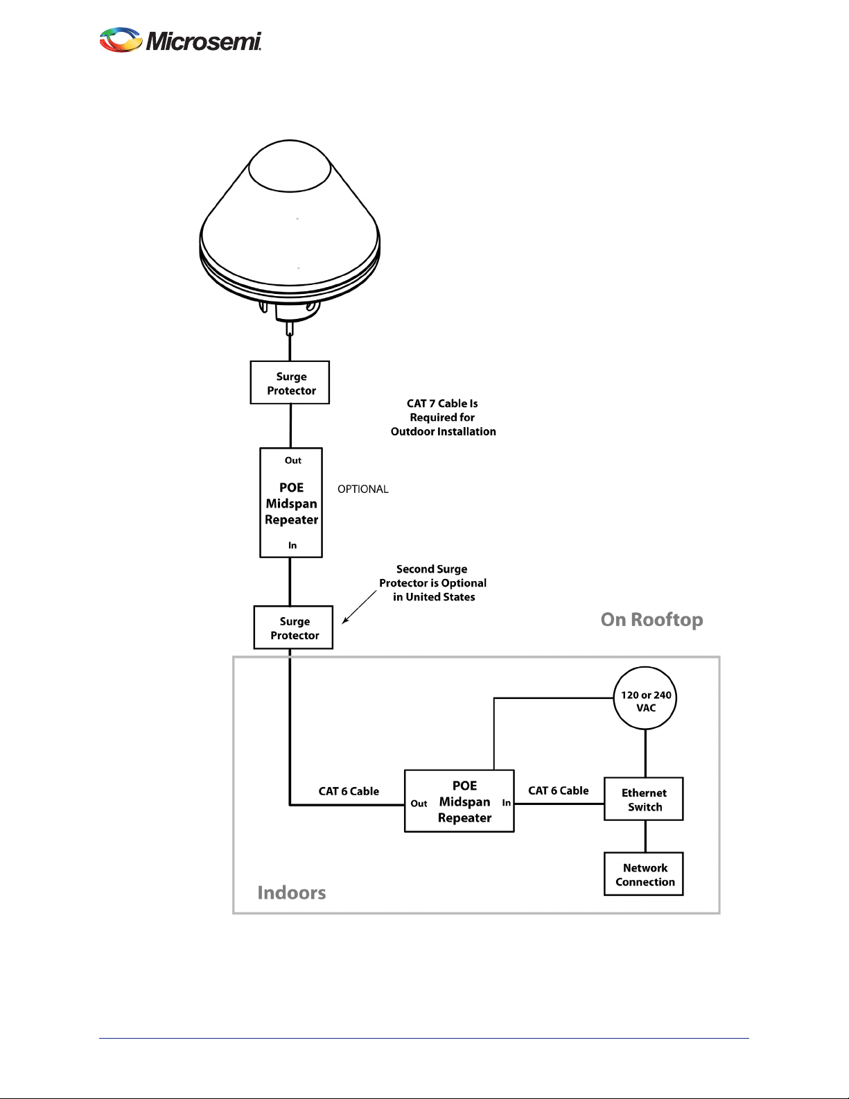
Installation of SyncServer S80
Figure 2-1 • SyncServer S80 Connection Diagram
10 098-00777-000 Rev. A
Page 11

Installation Tools and Equipment
You will need the following tools and equipment to install the SyncServer S80:
• Standard tool kit
• Cat 7 waterproof cables (lengths depends on layout)
Unpacking the Unit
The SyncServer S80 (p/n 090-15200-080) is packaged to protect them from normal shock, vibration and
handling damage. (Each unit is packaged separately.)
Unpack and inspect the unit as follows:
1. Wear a properly grounded protective wrist strap or other ESD device.
2. Inspect the container for signs of damage. If the container appears to be damaged, notify both the
carrier and your Microsemi distributor. Retain the shipping container and packing material for the
carrier to inspect.
3. Open the container, being careful to cut only the packaging tape.
4. Locate and set aside the printed information and paperwork that is included in the container.
5. Remove the unit from the container and place it on an anti-static surface.
6. Locate and set aside small parts which may be packed in the container.
7. Remove the accessories from the container.
8. Remove the anti-static packaging from the unit and accessories.
9. Verify that the model and item number shown on the shipping list agrees with the model and item
number on the equipment. The item number can be found on a label affixed to the bottom of the
unit. See See Figure 2-6 for the location of the label on the SyncServer S80. Contact your
Microsemi distributor if the model or item number do not match.
The SyncServer S80 includes the Ethernet system (including sealant strip) shown in Figure 2-10, which
is used to attach to the customer’s cable and provide a weatherproof seal. For a complete listing of items
in the installation kit, see Tab le 2 -1 . For a complete listing of items in the antenna cable bracket kit, see
Table 2-2.
SyncServer S80 NTP User Guide
Table 2-1 • SyncServer S80 Installation Kit - P/N 093-00741-000
Description Quantity Part Number
INSTALLATION SUPPORT, OUTDOOR
ANTENNA
LOCK NUT, CONDUIT FITTING, 1-1/4 NPT SIZE
THREAD, 2.281" O.D., 0.17" THICK, STEEL,
ROHS COMPLIANT
SCREW, MACHINE, 1/4-20, 0.500" LONG, PAN
HEAD, PHILLIPS, STEEL, ZINC PLATE
WASHER FLAT, 1/4" SCREW SIZE, 0.281"ID,
0.625"OD, 0.043"-0.057" THICK, 316 SS, ROHS
Table 2-2 • SyncServer S80 Antenna Cable Bracket Kit - P/N 093-00001-01
Description Quantity Part Number
BRACKET ANTENA MOUNT RA DUAL 1 070-00377-01-2
FORM V-BOLT M6 SS 2 070-00389-01-2
SCR MACH #10-32 PHILLIPS PH .125L SS 4 125-10034-02-1
1 070-02006-000
2 125-00434-000
1 125-00016-000
1 2821367
098-00777-000 Rev. A 11
Page 12
Installation of SyncServer S80
Table 2-2 • SyncServer S80 Antenna Cable Bracket Kit - P/N 093-00001-01 (continued)
Description Quantity Part Number
SCR SHEET-METAL #12 PHILLIPS PAN-HEAD
3/4"-LNG SS
NUT MACH HEX #M6 SS NYLON INSERT 4 126-24704-00-2
WASHER FLAT #M6 SS 4 126-14704-00-2
Mounting Site Location
Mount the antenna outside, preferably on the roof with an unobstructed view of the sky. Do not mount the
antenna near a wall or other obstruction blocking part of the sky. Mount the antenna well above roads or
parking lots. Proper cable, grounding techniques, and lightning arrestors should be used.
Warning:To avoid serious personal injury or death, exercise caution when working near high voltage lines.
In particular:
– Use extreme caution when installing the antenna near, under, or around high voltage lines.
– Follow local building electrical codes for grounding the chassis.Surge Protection for Indoor
PoE.
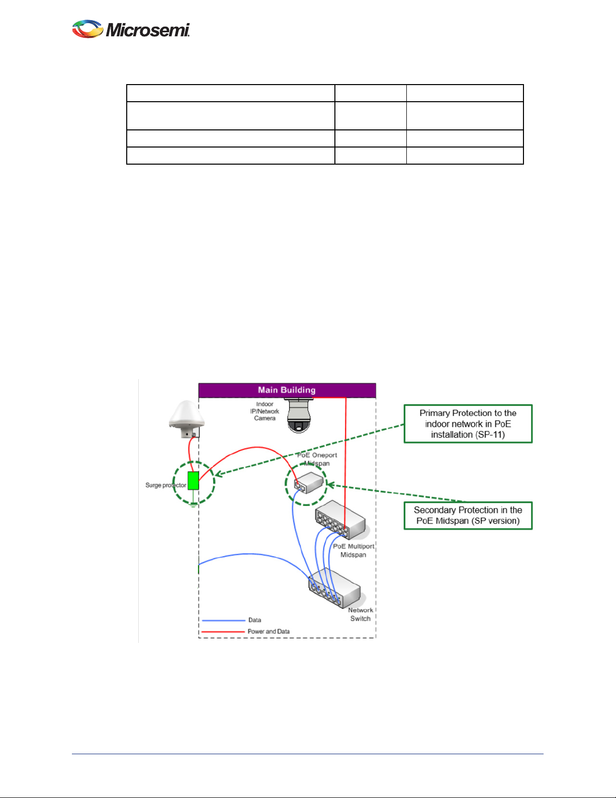
An indoor PoE should be isolated. It needs to a be single port injector, such as Microsemi’s PD-9001G40/SP Midspan. The Primary surge protection device needs to be as close as possible to inlet to the
building and connected to earth ground. The Microsemi PD-OUT/SP11 is recommended. The single port
PoE injector acts as secondary surge protection. See Figure 2-2.
2 125-12054-12-2
Figure 2-2 • Surge Protection with Indoor PoE
Surge Protection for Outdoor PoE
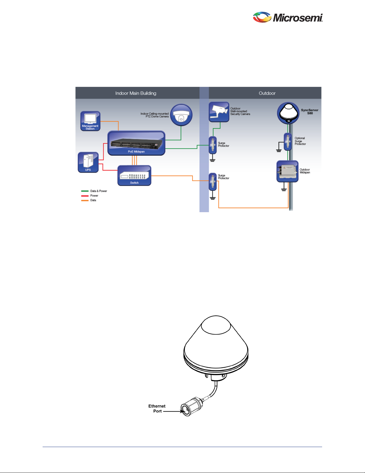
Using an outdoor PoE only makes sense for more than 1 outdoor device, for instance 1 SyncServer S80
and 1 outdoor security camera. Suggested Microsemi PoEs include the 2 port PDS-102GO or 4 port
12 098-00777-000 Rev. A
Page 13
SyncServer S80 NTP User Guide
PDS-104GO. See Figure 2-3.
The Sync Server S80 is compliant to ITU-K.20. A Lightning protector is required at both ends to be
compliant to ITU-K.20 (protecting the Antenna and the Building). Use state and local practices to assure
compliance measures are taken.The Microsemi PD-OUT/SP11 is recommended.
Figure 2-3 • Surge Protection with Outdoor PoE
Power Requirements
The SyncServer S80 receives power through Power Over Ethernet (PoE). The Power input to the unit
needs to be PoE Class 3.
Network Connection
The Ethernet port available through the cable on the bottom of the SyncServer S80 unit accepts an RJ45 connector, which links the unit to your 1 Gigabit Ethernet LAN. See Figure 2-4. The SyncServer S80
unit also receives power through the Ethernet cable from a POE power injector. The Ethernet MAC
address is printed on the label on the bottom of the SyncServer S80 unit.
Figure 2-4 • RJ-45 Ethernet Port on SyncServer S80 Unit
098-00777-000 Rev. A 13
Page 14

Installation of SyncServer S80
Recommended Tasks
Microsemi recommends the user configure the SyncServer S80 before mounting it in its outdoor or
rooftop location.
1. Make a temporary connection between the SyncServer S80 and the desired network. Refer to
Figure 2-1 for placement of the PoE midspan repeater.
2. Establish an SSH connection from your computer to the IP address assigned to the SyncServer
S80.
Note: The S80 default IP address is 192.168.100.11, the subnet mask is 255.255.255.0, and the gateway
address is 0.0.0.0 (no gateway).
Note: The Ethernet interface must be 1000 Base-T. Lower speed connections are not supported.
3. Type the default user name admin and press Enter.
4. Type default password Microsemi and press Enter. The system prompt will appear.
Note: Microsemi recommends using a static IP address. Whenever any IP address or mode is changed,
the S80 must be rebooted. Users are not recommended to use DHCP for the SyncServer S80
because there is no convenient method for retrieving assigned DHCP address for the management
port after reboot.
5. Set the desired IPv4 or IPv6 address using the
IPv4 Example
To set the static IPv4 address for the Ethernet Interface to 192.168.2.11, the mask to 255.255.255.0,
and the gateway 0.0.0.0:
S80> set ip ipv4 ip-address 192.168.2.11 netmask 255.255.255.0 and gateway
0.0.0.0:
S80> set ip ipv4 ip-address 192.168.2.11 mask 255.255.255.0 gateway 0.0.0.0
S80> set ip ipv4 state enable
S80> set ip ipv4 state restart
IPv6 Example
To set the static IPv6 address for the Ethernet Interface to 2201:db8:1234::11 , the prefix to 64, and
the gateway 2201:db8:1234::1:
S80> set ip ip6 ip-address 2201:db8:1234::11 prefix 64 gateway 2201:db8:1234::11
S80> set ip ipv6 state enable
S80> set ip ipv6 state restart
set ip command.
Caution:Microsemi strongly recommends that you record the serial number, hostname and MAC of
the SyncServer S80 before installing it.
Table 2-3 • Record Important System Settings and Values
Parameter Value
IPv4 Address
IPv4 Prefix
IPv4 Default Router
IPv6 Address
IPv6 Prefix
IPv6 Default Router
MAC Address
Serial Number
Hostname
14 098-00777-000 Rev. A
Page 15

Installing the SyncServer S80 Outdoors
Use the following procedure to install the SyncServer S80 outdoors. Typical installation requires
mounting and grounding two surge protectors. The first surge protector should be mounted as close as
possible to the SyncServer S80. The second surge protector should be mounted in the entrance to the
indoor building.
1. Identify the outdoor location for mounting the SyncServer S80 unit.
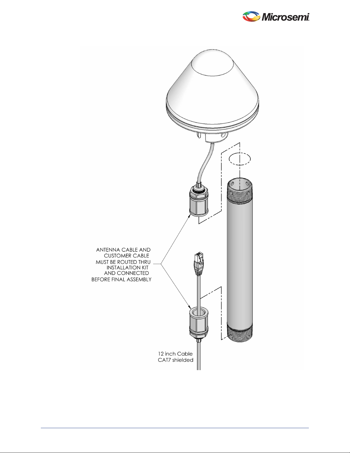
2. Guide the customer-supplied waterproof 12-inch CAT7 Ethernet cable and RJ-45 connector of the
SyncServer S80 through the bottom of the mounting pole (070-02006-000). As partially shown in
Figure 2-9, the cable must first pass through a pipe nut, then the mounting bracket, then through
the second pipe nut.
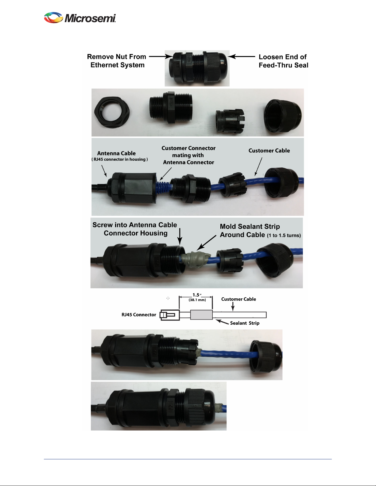
3. Remove the nut on the Ethernet System and loosen the feed-thru seal, as shown in Figure 2-10.
4. Guide the customer-supplied cable through the feed-thu seal and other components of the
Ethernet system, as shown in Figure 2-10.
5. Remove the plastic from both sides of the sealant. Place and mold the sealant around the
customer-supplied cable, as shown in Figure 2-10.
6. Plug the RJ45 connector of the customer-supplied CAT7 cable into the Ethernet port of the
SyncServer S80, as shown in Figure 2-10.
7. Screw the end of the Ethernet system into the Antenna connector housing, as shown in
Figure 2-10.
8. Reassemble the Ethernet system, and tighten the feed-thru seal, as shown in Figure 2-10.
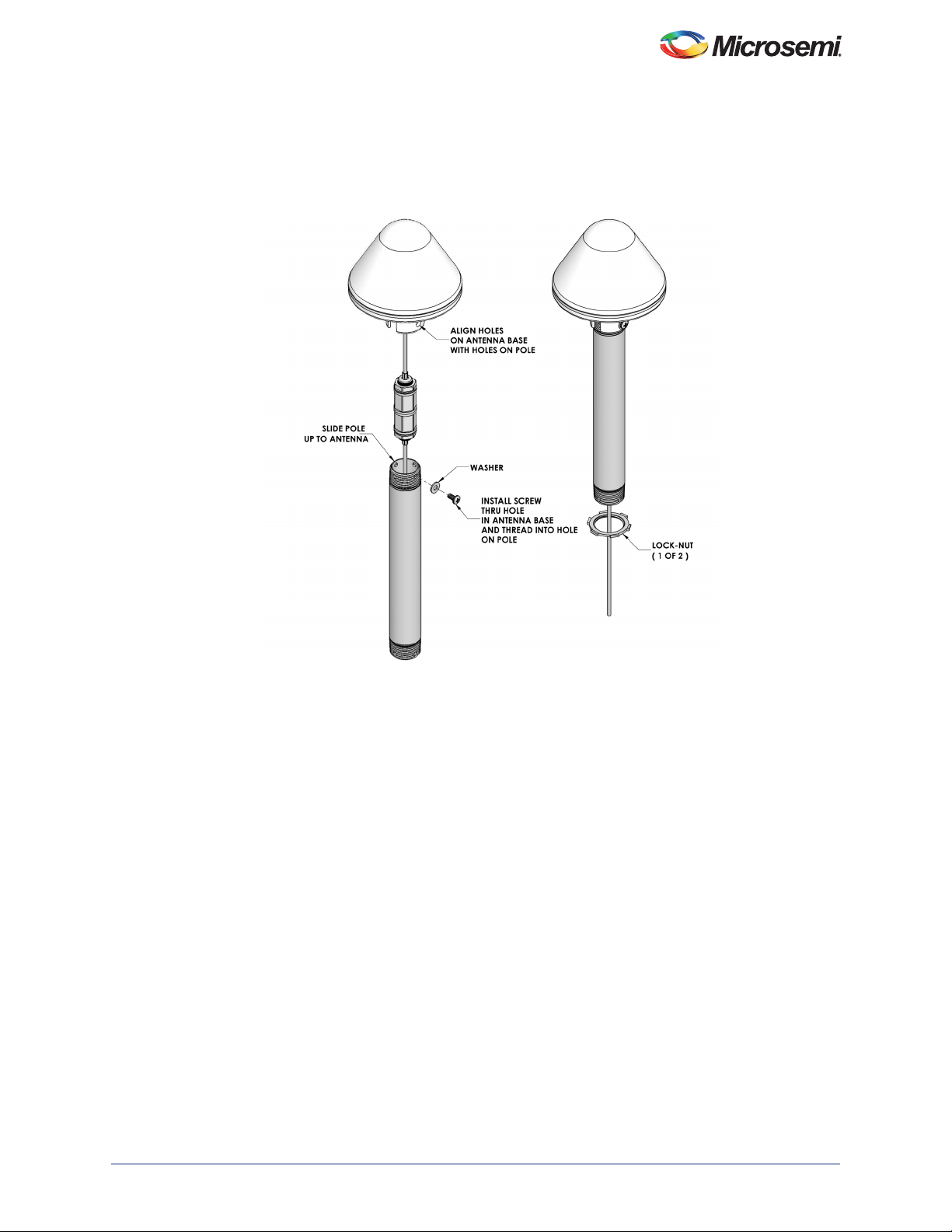
9. Gently pull the customer-supplied cable at the opposite end of the mounting pole to remove any
slack, sliding the Ethernet system into the top of the mounting pole. Continue until the top of the
mounting pole fits into the Antenna.
10. Attach the SyncServer S80 unit to the top of the mounting pole, and secure it using the screw and
washer from the Installation Kit (093-00741-000).
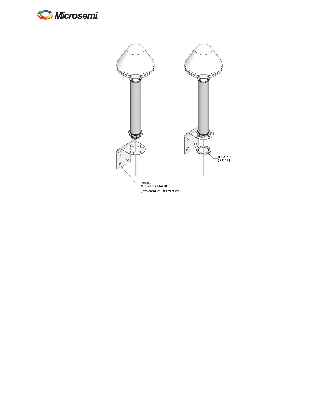
11. Screw the first pipe nut onto the bottom of the mounting pole, as shown in Figure 2-11.
12. Attach the mounting bracket (093-00001-01) to the bottom of the mounting pole, as shown in
Figure 2-12. Screw the second pipe nut onto the bottom of the mounting pole.
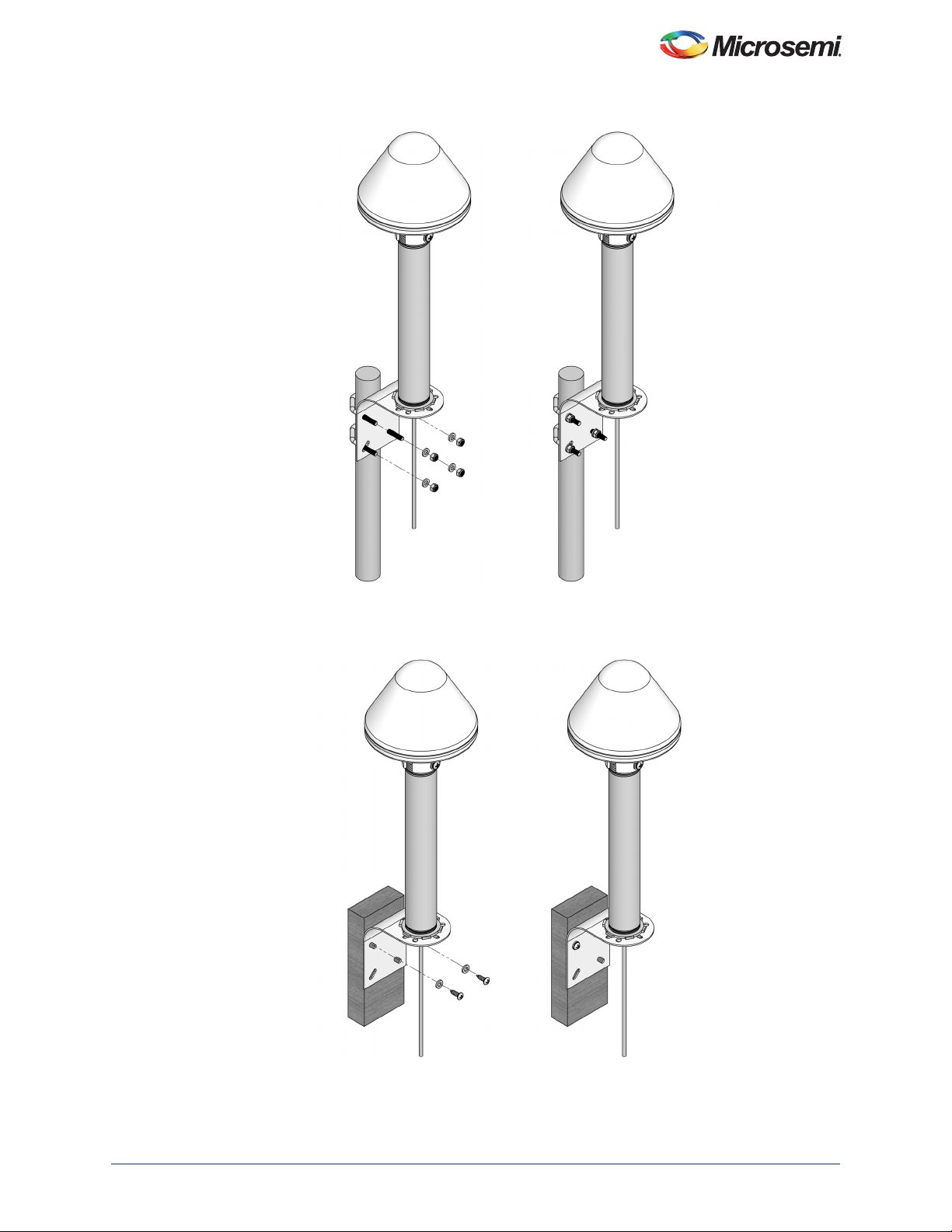
13. If mounting the SyncServer S80 to a mast, attach the mounting bracket to the pole with the
included U-bolts, as shown in Figure 2-13.
14. If mounting to a vertical surface, attach the mounting bracket with the included screws, as shown
in Figure 2-14. Adhere to local building codes to determine the type and number of fasteners,
screws, bolts, etc. that may be required.
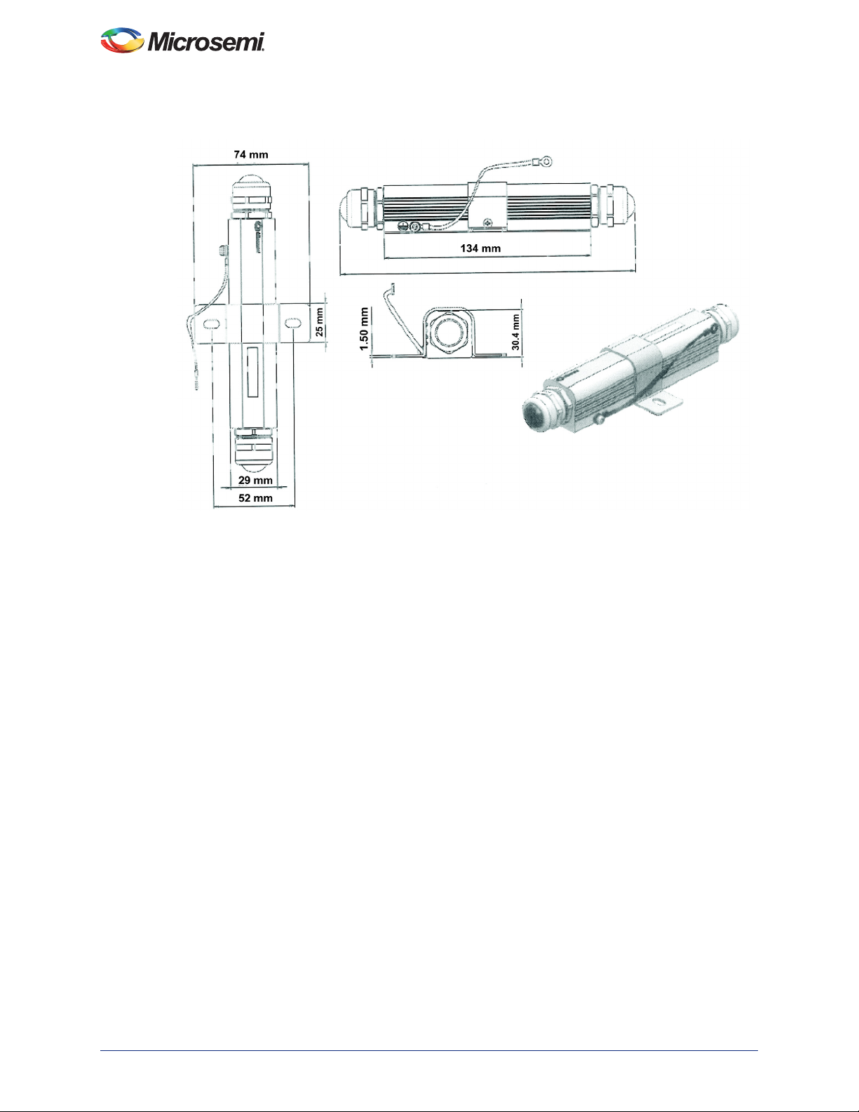
15. Mount the surge protector to the mast or vertical surface on which the SyncServer S80 is
mounted., close to the unit. See Figure 2-15 for surge protector dimensions.
16. If mounting to a mast, first remove the bracket by unscrewing both of its screws. Attach the surge
protector to the mast using a worm gear clamp. See Figure 2-17.
17. If mounting to a vertical surface use the attached bracket on the surge protector and mounting
screw to attach to the unit to the surface. See Figure 2-18 for an example of mounting the unit to
a vertical surface with the bracket.
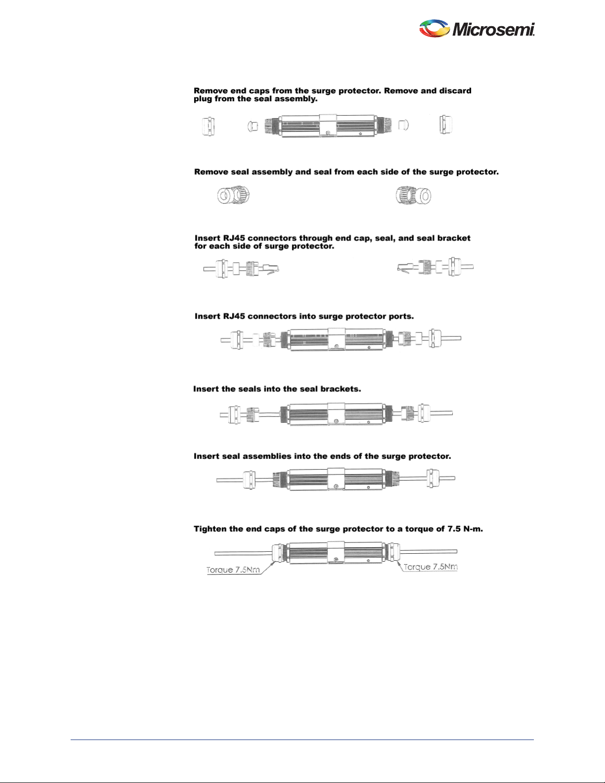
18. Plug the other end of the customer-supplied waterproof 12-inch CAT7 Ethernet cable into the
"Line" end of the surge protector. See
protector.
19. Plug the second customer-supplied waterproof CAT7 Ethernet cable into the "Equip" end of the
surge protector. See Figure 2-16 for details about connecting to the surge protector.
20. Ground the surge protector unit using the GND screw and strap.
21. Mount the second surge protector at the point where the cable enters the building. See
Figure 2-18 for an example.
22. Plug the other end of the second customer-supplied waterproof CAT7 Ethernet cable into the
"Line" end of the second surge protector. See Figure 2-16 for details about connecting to the
surge protector.
Figure 2-16 for details about connecting to the surge
SyncServer S80 NTP User Guide
098-00777-000 Rev. A 15
Page 16
Installation of SyncServer S80
23. Plug the third customer-supplied Ethernet cable into the "Equip" end of the surge protector. See
Figure 2-16 for details about connecting to the surge protector.
24. Ground the surge protector unit using the GND screw and strap.
25. Plug the end of the third customer-supplied Ethernet cable to the Output end of the power injector
or POE midspan repeater, as shown in Figure 2-1.
26. Plug a second Ethernet cable into an unpowered Ethernet port on your network.
27. Plug the other end of the Ethernet cable into the Input port of the power injector or POE midspan
repeater, as shown in Figure 2-1.
28. Plug the Power Input of the power injector or POE midspan repeater into an approved 100- to
240-VAC outlet or other suitable power source.
-
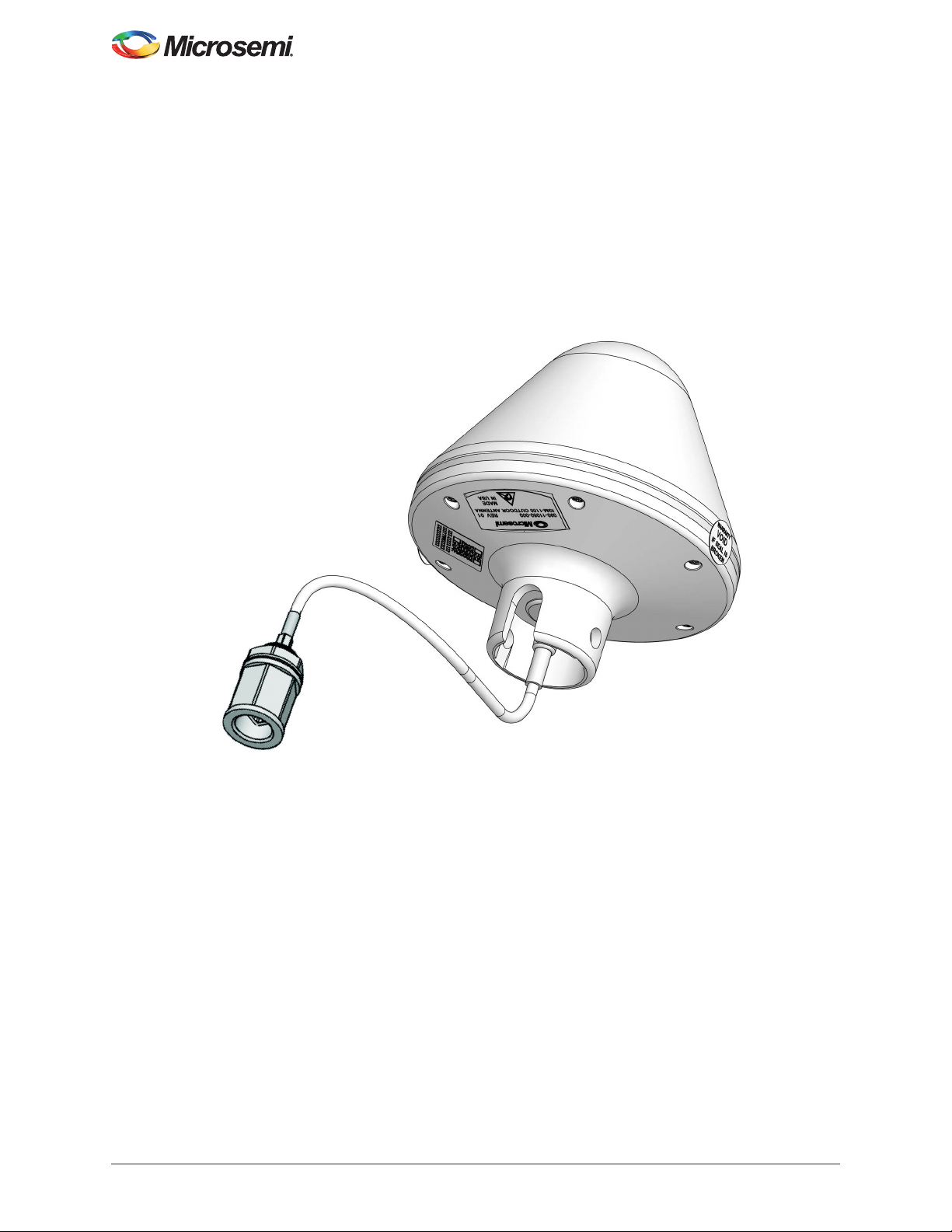
Figure 2-5 • SyncServer S80
16 098-00777-000 Rev. A
Page 17
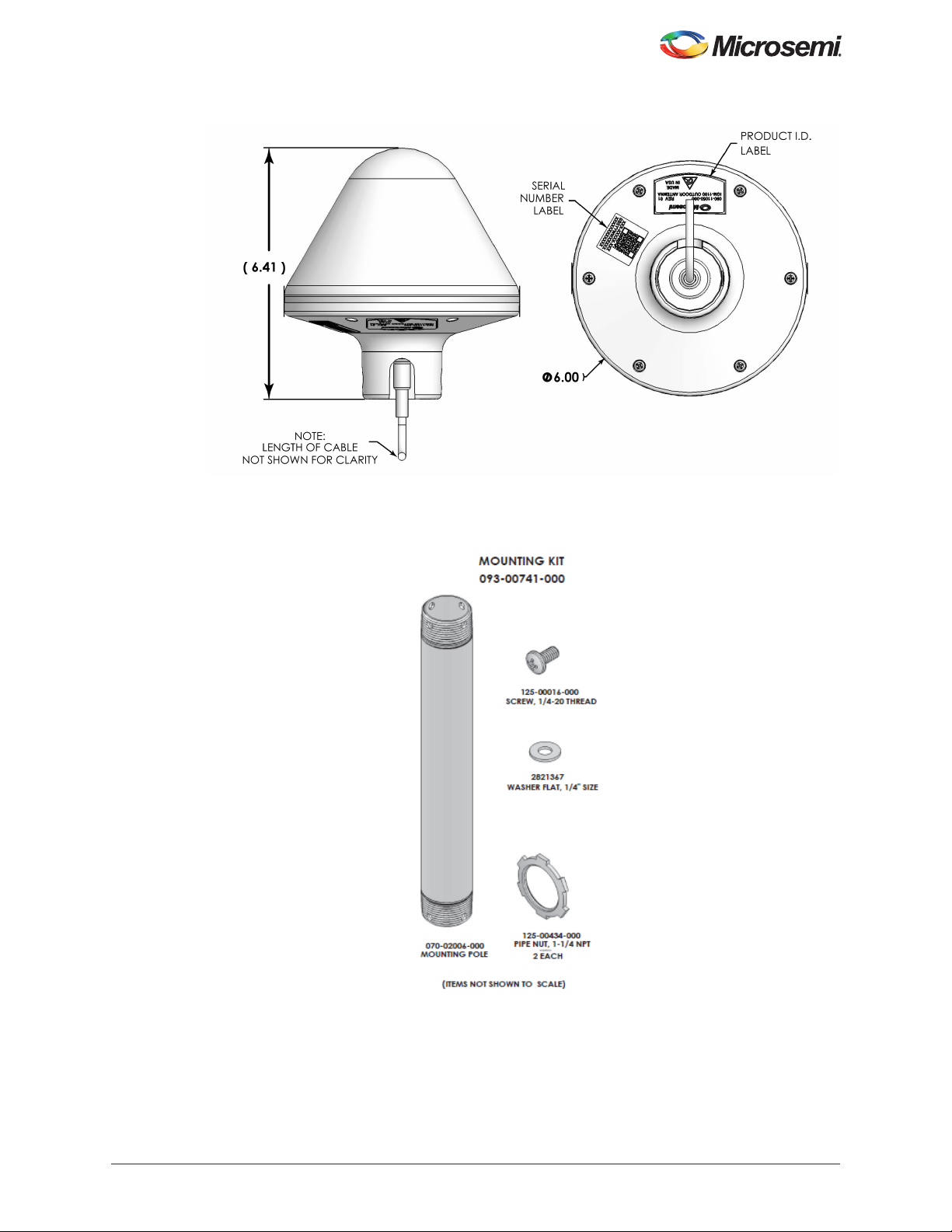
Figure 2-6 • SyncServer S80 Dimensions
SyncServer S80 NTP User Guide
Figure 2-7 • Mounting Kit for SyncServer S80
098-00777-000 Rev. A 17
Page 18

Installation of SyncServer S80
Figure 2-8 • Installation Bracket for SyncServer S80
18 098-00777-000 Rev. A
Page 19
SyncServer S80 NTP User Guide
Figure 2-9 • Cable Routing Before Final Assembly
098-00777-000 Rev. A 19
Page 20
Installation of SyncServer S80
Figure 2-10 • Connecting Customer Cable to Antenna Detail - Sealant Strip
20 098-00777-000 Rev. A
Page 21
SyncServer S80 NTP User Guide
Figure 2-11 • Attaching SyncServer S80 to Pole
098-00777-000 Rev. A 21
Page 22
Installation of SyncServer S80
Figure 2-12 • Attaching SyncServer S80 and Pole to Bracket
22 098-00777-000 Rev. A
Page 23
SyncServer S80 NTP User Guide
Figure 2-13 • Mounting SyncServer S80 to a Mast
Figure 2-14 • Mounting SyncServer S80 to a Vertical Surface
098-00777-000 Rev. A 23
Page 24
Installation of SyncServer S80
Figure 2-15 • Surge Protector Dimensions
24 098-00777-000 Rev. A
Page 25
SyncServer S80 NTP User Guide
Figure 2-16 • Connecting Surge Protector
098-00777-000 Rev. A 25
Page 26
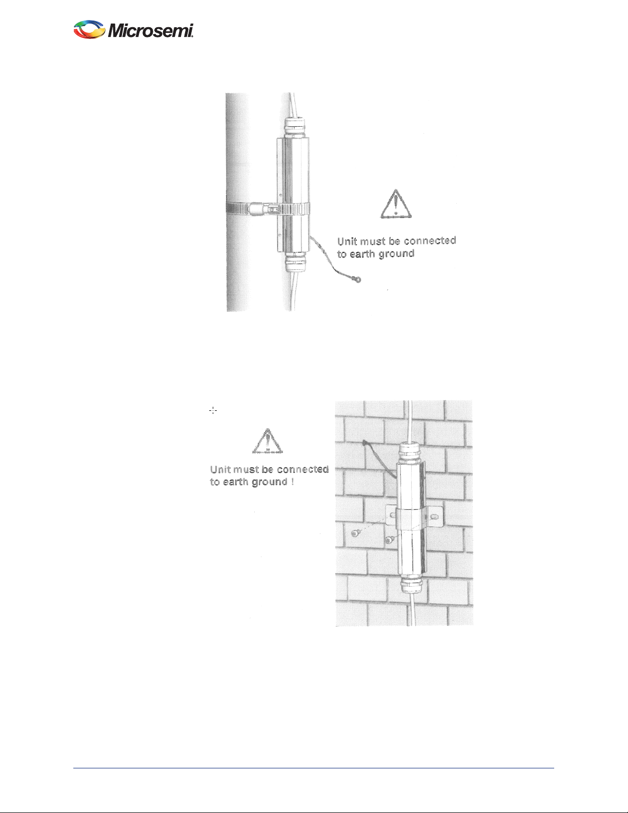
Installation of SyncServer S80
Figure 2-17 • Mounting Surge Protector on Pole
Figure 2-18 • Mounting Surge Protector on Outdoor Wall
26 098-00777-000 Rev. A
Page 27

3 – CLI Commands
This chapter describes how to use CLI commands to manage the SyncServer S80.
Using CLI Commands
The Command Line Interface (CLI), also called the ASCII command set, can be used to control the S80
from a terminal connected to the Ethernet port. See below for an overview of the command set.
S80 CLI Command Conventions
The following are conventions used for the S80 CLI command set:
• Commands are case sensitive
• { } - Braces indicate more than one parameter data option. When entering options in the CLI
command, enter one option from those available within the braces. Options within braces { } are
separated by a pipe ( | ).
• [ ] - Brackets provide information about the allowed range. The first value is the minimum, and the
last value is the maximum.
• < > - Brackets indicate that a value must be entered.
• Bold highlights keywords in the command syntax
• Italics indicate variable options.
CLI Command Keyboard Usage
After entering a command, you may see <enter>. This is a prompt for you to press ENTER to execute the
command that you entered.
The ? (SHIFT+QUESTION MARK) accesses the CLI online help. It can be used at any time while typing
a command (including at the prompt) to provide continuation options. These options include brief
descriptions of commands, or data type, format, and range.
Command Line Format
The command line format is as follows:
[Verb] Command [Parameter] [Data] EOL
• Verb - the type of action to be taken with the command.
– Set - enables you to provision a defined parameter.
– Show - enables you to display the provisioned state of a parameter.
• Parameter - command input that defines the particular command element to be shown or
modified.
• Data - the data input for the parameter.
• EOL - this parser responds only to <CR Return>. When the parser receives <CR Return>, the
input is terminated, and the command line entry is processed.
Command User Levels
The S80 provides a user logon for each of three user levels, whose capabilities are described below.
There is a single username for each level with usernames: "admin", "config", and "user". Factory preset
passwords for each of these logons is "Microsemi".
The capability of each user level is as follows:
098-00777-000 Rev. A 27
Page 28

CLI Commands
1. User class, with read-only permission, can change own password
2. Config class, with read-write rights, can change own password
3. Administrator class, with read-write rights, can change own password and can also change
password for config and user login.
S80 Command Set
This section provides an alphabetical listing and details of all CLI commands that are available while in
CLI mode. The list below provides a summary of all CLI commands .
• "show alarm"
• "show alarm-config:"
"set alarm-config:"
• "show bridge-time:"
"set bridge-time:"
• "show clock"
"set clock:"
• "set configuration:"
• "show gnss"
"set gnss"
• "show hostname"
"set hostname"
• "show inventory"
• "show ip"
"set ip"
• "show license"
"set license"
• "show lldp"
"set lldp"
• "show log"
"set log"
• "show log-config"
"set log-config"
• "logout"
• "show ntp"
"set ntp"
• "password"
• "ping"
• "reboot"
• "show snmp"
"set snmp"
• "show status"
• "upgrade"
28 098-00777-000 Rev. A
Page 29

SyncServer S80 NTP User Guide
show alarm
Use this command to display the system's standing (active) alarms and events.
Command Syntax:
show alarm
Level:
User, Config and Admin
Example:
S80> show alarm
Response:
Alarms:
Date-Time ID index Severity Descriptions
2017-04-17 11:48:55, 098, index = 000, ALARM SEVERITY: EVENT,GNSS PPS
failed
2017-04-17 11:48:50, 002, index = 000, ALARM SEVERITY: MINOR,Entered
time free-run state
2017-04-17 11:48:50, 002, index = 001, ALARM SEVERITY: MINOR,Entered
frequency free-run state
098-00777-000 Rev. A 29
Page 30

CLI Commands
show alarm-config:
Displays the alarm configuration including alarm ID, severity, state, reporting delay and description for
S80 alarms. This also displays if the alarm is transitory.
Command Syntax:
show alarm-config
Level:
User, Config and Admin
Example:
S80> show alarm-config
Response:
ID Severity State Delay Event/Alarm Descriptions
1 Minor enable 0 "Entered time/frequency warm-up state"
2 Minor enable 0 "Entered time/frequency free-run state"
3 Event enable 0 "Entered time/frequency fast-track state"
4 Event enable 0 "Entered time/frequency normal-track state"
5 Event enable 0 "Entered time/frequency bridging state"
6 Minor enable 0 "Entered time/frequency holdover state"
8 Minor enable 0 "Entered time/frequency holdover rec state"
21 Minor enable 0 "GNSS input assessing"
22 Event enable 0 "GNSS input time qualified"
23 Event enable 0 "GNSS input freq qualified"
24 Event enable 0 "GNSS input selected as time reference"
25 Event enable 0 "GNSS input sel as freq ref"
51 Minor enable 0 "Incompatible transport type"
91 Minor enable 0 "GNSS receiver communications failed"
92 Minor enable 0 "GNSS receiver not tracking satellite"
98 Event enable 0 "GNSS PPS failed"
99 Event enable 0 "GNSS Base Config failed"
111 Minor enable 0 "Ethernet port link down"
112 Minor enable 0 "Excessive traffic on port ETH"
137 Critical enable 0 "PLL synthesizer unlock"
139 Minor enable 0 "Temperature out of range"
152 Event enable 0 "Timeline has been changed"
153 Event enable 0 "Phase has been aligned"
155 Event enable 0 "System reboot"
156 Event enable 0 "Ethernet speed"
157 Event enable 0 "Gnss acquisition status"
179 Event enable 0 "NTP Stratum Change"
180 Event enable 0 "NTP Leap Change"
181 Event enable 0 "NTP Passive mode"
182 Event enable 0 "NTP Active mode"
183 Event enable 0 "NTP Service load limit"
set alarm-config:
Use this command to provision the alarm state, alarm level, and reporting delay time for the specified
alarms. The reporting delay time is the amount of time from when the alarm occurred to when it is
reported. The delay parameter will delay the reporting of an alarm by the configured amount.
Command Syntax:
• To provision the state of the specified alarm number:
set alarm-config state {alarm [1 to 163] | all} {enable | disable}
• To provision the level of the specified Alarm number:
set alarm-config level {alarm [1 to 163] | all} {2 |3 | 4 | 5}
Where:
– 2 - Critical
– 3 - Major
30 098-00777-000 Rev. A
Page 31

SyncServer S80 NTP User Guide
– 4 - Minor
–5 - Event
• To provision the reporting delay of the specified Alarm number in seconds:
set alarm-config delay {alarm [1 to 163] | all}value [0 to 500000]
Level:
Config and Admin
Example 1:
To Disable alarm:
S80> set alarm-config state alarm 5 disable
Example 2:
To set the severity level of alarm 5 to major (3):
S80> set alarm-config level alarm 5 3
Example 3:
To set the reporting delay of alarm 5 to 19 seconds:
S80>set alarm-config delay alarm 5 value 19
098-00777-000 Rev. A 31
Page 32

CLI Commands
show bridge-time:
Use this command to display the bridging time that is used to allow the frequency servo to coast through
short periods when the system does not have qualified GPS/GLONASS reference. The bridging time is in
seconds.
Command Syntax:
show bridge-time
Level:
User, Config and Admin
Example:
S80> show bridge-time
Response:
Bridging Time : 300
Note: If the system has not qualified a time or frequency reference within the specified bridging time the
set bridge-time:
Provisions the amount of time, in seconds, the system remains in bridging mode before transitioning into
the holdover mode of operation. The bridge-time applies to both clock-timing loop and clock-frequency.
The range is 120 - 86400 seconds.
Command Syntax:
set bridge-time <time-value>
Level:
Config and Admin
Example:
S80> set bridge-time 300
system transitions into holdover mode of operation.
32 098-00777-000 Rev. A
Page 33

SyncServer S80 NTP User Guide
show clock
This command displays the system date, time, and leapseconds in several formats.
• Current system date and time
• Accumulated leapseconds between TAI and UTC time
• Pending leapseconds
Command Syntax:
show clock
Level:
User, Config and Admin
Example:
S80> show clock
Response:
System time : Tue Apr 18 11:32:49 2017
Leap Seconds : 36
Leap pending : 0
set clock:
Provisions the user-assigned Date, Time, and accumulated leapseconds.
Command Syntax:
• To set the Date and Time:
set clock date-time <date-time>
Enter date and time in YYYY-MM-DD,HH:MM:SS format (UTC)
• To set the Accumulated leapseconds:
set clock leapseconds <value>
Level:
Config and Admin
Example 1:
S80> set clock date-time 2016-08-05,22:35:24
Example 2:
To set the accumulated leapseconds to 29 seconds:
S80> set clock leapseconds 29
098-00777-000 Rev. A 33
Page 34

CLI Commands
set configuration:
Use this command to set the current configuration to factory settings. Factory removes all attributes. Use
of this command results in reboot of the S80.
Command Syntax:
set configuration factory
Level:
Config and Admin
Example 1:
To set the factory configuration
S80> set configuration factory
34 098-00777-000 Rev. A
Page 35

show gnss
This command displays the GNSS port state and elevation mask value.
Command Syntax:
• To show antenna-current qualification:
show gnss antenna-current:
• To show GNSS configuration:
show gnss config
• To show GNSS status:
show gnss status
• To show GNSS monitor info:
show gnss monitor-info
Level:
User, Config and Admin
Example 1:
S80>Show gnss config
Response 1a:
GNSS Configuration
GNSS Status : enable
elevation_mask : 7
Track-Mode : gps
Pos-Mode : auto
Antenna Delay : 0
SyncServer S80 NTP User Guide
GNSS manual position
Latitude : N37:22:43.425
Longitude : W121:55:34.815
Height : 13.7
Response 1b:
GNSS Configuration
GNSS Status : enable
elevation_mask : 5
Track-Mode : gps+glonass
Pos-Mode : Dynamic Model Automotive
Antenna Delay : 313
GNSS manual position
Latitude : N37:22:43.425
Longitude : W121:55:34.815
Height : 13.7
Example 2:
S80>Show gnss antenna-current
Response 2:
Antenna-current qualification : enable
Example 3:
S80> show gnss status
Response 3:
used-sats : 0
acquisition-status : 1
no-sat-dur : 55
satellite-view : none
098-00777-000 Rev. A 35
Page 36

CLI Commands
latitude : 0.000000
longitude : 0.000000
altitude : 0.000000
hdop : 0.000000
fix-quality : 0
pdop : 0.000000
op-mode : 1
GNSS Status :
Current Status : disqualified
Current Reference Status : fault
Current Position Status : surveying
Current Antenna Position :
Latitude : N00:00:00.00
Longitude : E000:00:00.00
Height : 0.00
Example 4:
S80> show gnss monitor-info
Response 4:
hw-aStatus: 1
hw-flags : 0x00
hw-jamInd: 83
io-rxBytes: 15140
io-txBytes: 8184404
io-parityErrs: 0
io-framingErrs: 0
io-overrunErrs: 0
survey-in-duration : 7754
survey-in-observation : 0
survey-in-postion-valid : 0
survey-in-progress : 1
pdop : 99.989998
fixType : 0,NO-Fix
numSv : 0
set gnss
This command allows the user to set the cable delay and the elevation mask. the angle below which the
satellites are not used by the system. It allows the user set the track mode for GPS only (disable) or GPS
+ GLONASS (enable).
This command also allows the user to set the position mode to auto (default) for stationary or dynamic. At
startup, the S80 is in survey mode. For Auto position mode, the S80 fixes its position at the stationary
location. For dynamic positioning mode, the S80 will "survey always" but the user can set for Automotive
or Sea. (The "Air" setting is for future use and not currently supported.)
Command Syntax:
• To set the GNSS state:
set gnss state {enable | disable}
Note: If GNSS is disabled, the S80 still shows satellites tracked but doesn’t provide valid time and freq.
• To set the GNSS elevation mask:
set gnss mask {5 to 60}
Note: SyncServer S80
• To set the GNSS cable delay value:
set gnss cable-delay {0 to 9999}
• To set the GNSS position mode:
36 098-00777-000 Rev. A
Page 37

set gnss posmode {auto | dynamic}
• To set the GNSS dynamic position mode:
set gnss posmode dynamic {0 | 1 | 2}
where
0 = Automotive
1 = Sea
2 = Air (Not Valid Choice for S80)
• To set the GNSS track-mode state for GLONASS:
set gnss track-mode glonass {enable | disable}
Note: Default is enable which = GPS + GLONASS
Level:
Config and Admin
Example 1:
To enable GNSS -
S80> set gnss state enable
Example 2:
To set the GNSS elevation mask to a value of 30 -
S80> set gnss elev 30
Example 3:
To set the GNSS cable delay to a value of 200 ns
S80> set gnss cable-delay 200
Example 4
To set the position mode to auto -
S80> set gnss posmode auto
Example 5
To set the track mode to GPS only -
S80> set gnss track-mode glonass disable
SyncServer S80 NTP User Guide
show hostname
This command displays the current host name for the unit.
Command Syntax:
show hostname
Level
User, Config, and Admin
Example:
S80> show hostname
Response :
Host name : S80
set hostname
This command sets the hostname for the unit. Hostname can contain up to 20 characters. Cli prompt, log
messages, system name in LLDP frame will get changed based on hostname.
Microsemi recommends setting a hostname. In the event that IP address is lost. you will be able to
identify the correct unit when retrieving the IP with LLDP utility. See "Provisioning for LLDP".
Command Syntax:
set hostname <hostname-string>
098-00777-000 Rev. A 37
Page 38

CLI Commands
Level
User, Config, and Admin
Example 1:
To set the hostname to Sync_R52 -
S80> set hostname Sync_R52
show inventory
Use this command to display product information for the S80.
Command Syntax:
show inventory
Level
User, Config, and Admin
Example:
S80> show inventory
Response:
product model : SYNCSERVER-S80
paet number : 090-15200-080
clei number : NA
serial number : SHZ152900027
software ver : 1.0.0
hardware ver : A
fpga version : 22
mac address : 00:b0:ae:03:e3:76
mfg status : FT-P,ST-P
pcba : LF17715260007,40350303628
• Product Model
• Part Number
• Clei Number
• Serial Number
• Software ver
• Hardware Ver
• Fpga Ver
• Mac address
• Manufacturing status
• Pcba
38 098-00777-000 Rev. A
Page 39

SyncServer S80 NTP User Guide
show ip
Use this command to display the status and current IP settings for the Ethernet
interface.
Command Syntax:
• To view configuration of the specified network interface:
show ip config
• To view status of the specified network interface
show ip status
Level:
User, Config, and Admin
Example 1:
S80> show ip status
Response 1:
Link encap:Ethernet HWaddr 00:50:56:b6:66:0c
inet addr:192.168.1.100 Bcast:192.168.1.1
Mask:255.255.255.0
inet6 addr: fe80::250:56ff:feb6:660c/64 Scope:Link
UP BROADCAST RUNNING MULTICAST MTU:1500 Metric:1
RX packets:38885460 errors:0 dropped:105037 overruns:0 frame:0
TX packets:23369349 errors:0 dropped:0 overruns:0 carrier:0
collisions:0 txqueuelen:1000
RX bytes:35465171789 (35.4 GB) TX bytes:19857282436 (19.8GB)
Example 2:
S80>show ip config
Response 2:
In IPv4 mode:
IP mode : dhcp
IP state : enable
Static mode Parameters
IP address : 192.168.1.111
IP mask : 255.255.255.0
IP gateway : 0.0.0.0
In IPv6 mode:
IP mode : dhcp
IP state : enable
Static mode Parameters
IP address : 192.168.1.111
IP mask : 255.255.255.0
IP gateway : 0.0.0.0
IPv6 mode : static
IPv6 state : enable
Static mode Parameters
IPv6 address : 2001:db8:1234::2
IPv6 prefix : 64
IPv6 gateway : 2001:db8::1
set ip
Use this command to set the address mode to DHCP (IPv4 or IPv6). Use this command to provision the
Host, Mask, and Gateway for IPv4 static addresses. Use this command to provision the Host, Prefix, and
Gateway for IPv6 static addresses..
098-00777-000 Rev. A 39
Page 40

CLI Commands
Note: The 128 bits of an IPv6 address are represented in 8 groups of 16 bits each. Each group is written
Command Syntax:
as 4 hexadecimal digits and the groups are separated by colons (:).
For convenience, an IPv6 address may be abbreviated to shorter notations by application of the
following rules, where possible.
Remove one or more leading zeroes from any groups of hexadecimal digits to either all or none of
the leading zeroes. For example, the group 0042 is converted to 42.
Replace consecutive sections of zeroes with a double colon (::). The double colon may only be
used once in an address, since multiple use would render the address indeterminate. RFC 5952
recommends that a double colon must not be used to denote an omitted single section of zeroes.
An example of application of these rules:
Initial address: 2001:0db8:0000:0000:0000:ff00:0042:8329
After removing all leading zeroes in each group: 2001:db8:0:0:0:ff00:42:8329
After omitting consecutive sections of zeroes: 2001:db8::ff00:42:8329
• To set the IPv4 address, mask and gateway of the Ethernet interfaces
set ip ipv4 ip-address <addr_value> netmask <mask_value>
gateway <gateway value>
• To set the IPv6 address, prefix and gateway of the Ethernet interfaces:
set ip ipv6 ip-address <addr_value> prefix <prefix_value> gateway <gateway_value>
• To set the IP address mode to DHCP or static:
set ip {ipv4|ipv6} address-mode {dhcp | static}
• To set the IP state of the port for IPv4 or IPv6 or to restart
set ip {ipv4|ipv6} state {enable | disable | restart}
Level:
Config and Admin
Example 1:
S80>set ip ipv4 address-mode dhcp
S80>Set ip ipv6 address-mode dhcp
Example 2:
S80> set ip ipv4 ip-address 192.168.1.100 mask 255.255.255.0 gateway 192.168.1.1
S80> set ip ipv6 ip-address 2201:db8:1234::2 prefix 64 gateway 2201:db8:1234::1
Example 3:
S80> set ip ipv4 state enable
S80> set ip ipv6 state enable
40 098-00777-000 Rev. A
Page 41

SyncServer S80 NTP User Guide
show license
Use this command to display the current feature-level licenses.
Command Syntax:
show license
Level:
Config and Admin
Example:
S80>show license
Response:
ntp-packets-capacity-500, NTP with capacity of 500 packets
per second
If no license is installed, the S80 unit shows NTP packet capacity of 500 (default).
If the NTP license is installed, the S80 will indicate NTP packet capacity of 1000.
set license
Use this command to enter the 40-character license key for new features, and to delete features. The
license is associated with the serial number of the system.
Command Syntax:
• To enter a license key for new features:
set license add <40-character license key>
• To delete a license key:
set license delete
The S80 will respond with all installed features that can be deleted.
Level:
Admin
Example 1:
To add a license with the 40-digit key 1234567890abcdefghij09875654321klmnopqrst:
S80>set license add 1234567890abcdefghij09875654321klmnopqrst
Note: After three unsuccessful attempts user can't add license for a block out period of 15mins. So, in that
block out period even the valid license will not be accepted. After 15 min. user can add valid license
successfully.
show lldp
This command displays the current LLDP state. When the LLDP state is enabled, LLDP frames are sent
out by S80 every minute and no frames are sent out when the state is disabled. Any computer connected
in LAN or back-to-back can know the details of S80 by capturing the LLDP frames sent by S80. The
LLDP frames sent by S80 consists information about Management port IP address, MAC address,
System name, System description, and Ethernet port number. This feature, which is enabled by default,
provides a way for the user to discover the management port IP address of the unit as there is no serial
port connection available. See Figure 5-1 for an example of a LLDP frame.
Command Syntax:
show lldp config
Level
User, Config, and Admin
Example:
S80> show lldp config
098-00777-000 Rev. A 41
Page 42

CLI Commands
Response :
LLDP State : enable
set lldp
This command sets the lldp state to enable or disable. When the LLDP state is set to enabled, LLDP
frames are sent out by the S80 every minute and no frames are sent out when the state is disabled. Any
computer connected in LAN or back-to-back can know the details of the S80 by capturing the LLDP
frames sent by the S80. The LLDP frames sent by the S80 consist of information about Management port
IP address, MAC address, System name, System description, and Ethernet port number. This feature
enables the user to know the management port IP address of the unit as there is no serial port
connection available.
Caution:Microsemi does not recommend disabling LLDP, becuase you will lose access to the method of
Command Syntax:
set lldp {enable | disable}
Level
Config, and Admin
Example 1:
To set the LLDP state to disable -
S80> set lldp disable
Example 2:
To set the LLDP state to enable -
S80> set lldp enable
retrieving a lost IP address. See "Recovering Lost IP Address with LLDP Utility" on page 64
show log
This command displays the specified log file (content) from the local storage. When showing the log
content, the Index parameter selects one of the seven rotated log files. The Head parameter, along with
the count value, displays the specified number of events from the beginning of the file. The Tail
parameter, along with the count value, displays the specified number of events from the end of the file. If
the Index is zero,the current log file is displayed. In order to get the latest x entries use file-index 0 and
tail x . To get the oldest x entries use file-index 6 and head x(assuming file 6 has been created and is full).
Command Syntax:
• To display the log content for a specified number of events -
show log {alarm-event | command | security } file-index <index-value> {head | tail}
<number-of-lines>
where:
head : <1 - 1000> Show first n number of lines from the log file
tail : <1 - 1000> Show last n number of lines from the log file
file-index: <0 - 6>
• To display the diagnostics logging state -
show log diag state
Level
User, Config, and Admin
Example 1:
To display the first 10 entries of alarm log (10 lines from the head of current log)
S80> show log alarm-event file-index 0 head 10
Response 1:
Apr 17 11:48:55 S80 local4.notice syslog: 098, index = 000, ALARM SEVERITY: EVENT,GNSS
PPS failed
42 098-00777-000 Rev. A
Page 43

SyncServer S80 NTP User Guide
Apr 17 11:56:52 S80 local4.notice syslog: 181, index = 000, ALARM SEVERITY: EVENT,NTP
Passive mode
Apr 17 12:27:52 S80 local4.notice syslog: 181, index = 000, ALARM SEVERITY: EVENT,NTP
Passive mode
Apr 17 12:45:55 S80 local4.notice syslog: 157, index = 002, ALARM SEVERITY:
EVENT,NO_SATS_GT60
Apr 17 21:54:53 S80 local4.notice syslog: 181, index = 000, ALARM SEVERITY: EVENT,NTP
Passive mode
……………..
Example 2:
S80> show log command file-index 0 tail 10
Response 2:
Apr 18 11:32:50 S80 local5.info syslog: [user: root]: show clock
Apr 18 11:33:44 S80 local5.info syslog: [user: root]: show alarm
Apr 18 11:35:02 S80 local5.info syslog: [user: root]: show status
Apr 18 11:39:05 S80 local5.info syslog: [user: root]: show snmp trapuser
Apr 18 11:39:08 S80 local5.info syslog: [user: root]: show snmp user
Apr 18 11:40:11 S80 local5.info syslog: [user: root]: show alarm-config
Apr 18 11:45:02 S80 local5.info syslog: [user: root]: show log alarm-event file-index 0
head 10
………………..
Example 3:
S80> show log diag state
Response 3:
Diagnostics Logging State : Enable
set log
Use this command to provision the state of debug message sent out to the debug log.
Command Syntax:
set log diag state <enable|disable>
Level
Config, and Admin
Example:
set log diag state enable
show log-config
This command displays the configuration for log size.
Command Syntax:
show log-config size {alarm-event | command | security}
Level
User, Config, and Admin
Example 1:
S80> show log-config size alarm-event
Response 1:
Log size of alarm-event is : 100 kilobytes
Example 2:
S80> show log-config size command
Response 2:
Log size of command is : 100 kilobytes
set log-config
Use this command to provision the specified log file buffer size, the maximum number of kilobytes to be
stored in the file before it is rotated. The range is 1 to 100 kilobytes, with a default of 100 kilobytes.
098-00777-000 Rev. A 43
Page 44

CLI Commands
Command Syntax:
set log-config size {alarm-event | command | security} <size-value>
Level
Config, and Admin
Example 1:
To set the alarm-event log size to 30 kilobytes -
S80> set log-config size alarm-event 30
Example 2:
To set the command log size to 50 kilobytes -
S80> set log-config size command 50
logout
This command terminates the current user connection.
Command Syntax:
Logout
Level:
User, Config, and Admin
Example:
S80>logout
show ntp
This command displays the current configuration and status of NTP for the unit.
Command Syntax:
show ntp {config | status }
Example 1:
S80> show ntp config
Response 1:
NTP status: Enabled
IP version: IPv4
TTL : 64
DSCP : 46
Max Packets: 500
Alarm Threshold: 100
Example 2:
S80> show ntp status
Response 2:
NTP STATUS
Port enabled: yes
IP version: 4
Mode : server
Reference ID: GNSS
Leap status: no warning
Stratum level: 16
Root dispersion: 4294.967296 sec
Packet load: 0%
set ntp
Use this command to set the DSCP, TTL, alarm threshold , IP version, state parameters of NTP for the
unit. The alarm threshold indicates the NTP service load (percentage of capacity) at which a system
message (#183) about the event will be generated.
Command Syntax:
• To set the DSCP value -
set ntp dscp <value>
44 098-00777-000 Rev. A
Page 45

SyncServer S80 NTP User Guide
• To set the TTL value -
set ntp ttl <value>
• To set the Alarm Threshold value -
set ntp alarmthresh [1-100]
• To set the IP version to IPv4 or IPv6 -
set ntp ipver {4 | 6}
• To enable of disable NTPset
ntp state {enable | disable}
Level : Config, and Admin
Example 1:
To set the NTP DSCP value to 45 -:
S80>set ntp dscp 45
Example 2:
To set the NTP TTL value to 65 -:
S80>set ntp dscp 65
password
Use this command to modify the password of the admin, config and user.
Command Syntax:
Password [admin | config | user}
Level :
User, Config, and Admin
Note: Each user level can change its own password. Additionally, "admin" user can modify "config" and
"user" passwords.
Example:
S80> password user
Response:
Changing password for user
New password:
Retype password
Password for user changed by user
S80>
ping
Use this command to ping the host specified by the address (xxx.xxx.xxx.xxx) and display ping statistics
from Ethernet.
Command Syntax:
• To ping an IPv4 address:
ping ipv4 <ipv4 address>
• To ping an IPv6 address:
ping ipv6 <ipv6 address>
Level:
User, Config, and Admin
Example 1:
S80> ping ipv4 address 192.168.201.11
Response 1:
Ping 192.168.201.11 SUCCESS
Example 2:
S80> ping ipv6 address 2000:2222:2222:2222:0:0:1:1
Response 2:
ping 2000:2222:2222:2222:0:0:1:1 SUCCESS
098-00777-000 Rev. A 45
Page 46

CLI Commands
Example 3:
S80> ping ipv4 10.60.132.71
Response 3:
Ping 10.60.132.71 FAILED
reboot
This command restarts the S80 system. Using this command can cause a loss of outputs.
Command Syntax:
reboot
Level : Admin only
Example:
Reboot
Response :
S80> reboot
System is going to reboot
The system is going down NOW!
Sent SIGTERM to all processes
TERM
Sent SIGKILL to all processes
Requesting systRestarting system.
U-Boot 2010.03-00002-gb955030 (May 26 2015 - 08:55:58)
CPU : SmartFusion2 SoC (Cortex-M3 Hard IP)
Freqs: CORTEX-M3=166MHz,PCLK0=83MHz,PCLK1=83MHz
Board: Falcon Rev 1A, www.microsemi.com
SW : Rev 1.2.8
DRAM: 128 MB
In: serial
Out: serial
Err: serial
Net: RWI_MAC
Hit any key to stop autoboot: 0
46 098-00777-000 Rev. A
Page 47

SyncServer S80 NTP User Guide
show snmp
Use these commands to display the SNMP Manager assigned to the agent, all assigned users
(username only), and the SNMP trap version and SNMP trap user.
Command Syntax:
• To show SNMP Manager assignment:
show snmp manager
• To show SNMPv3 User Configuration:
show snmp user
• To show SNMP trap user information:
show snmp trapuser
• To show SNMP v2-community information:
show snmp v2-community
• To show SNMP trap version information:
show snmp trapversion
• To show SNMP v2 state:
show snmp state-v2
Example 1:
S80> show snmp manager
Response 1:
SNMP engineID : 0x80001f880300b0ae03e376
Trap-IP : 192.168.1.100
Example 2:
S80> show snmp trapuser or user
Response 2:
SNMPv3 trap user name : testteam
security level : auth
Authentication Type : MD5
Authentication Key : ********
Example 3:
S80> show snmp trapversion
Response 3:
Trap version : SNMPv3
SNMP engineID : 0x80001f880300b0ae03e376
Trap-IP : 192.168.1.100
Example 4:
S80> show snmp state-v2
Response 4:
SNMP v2 state : enable
Example 5:
S80> show snmp v2-community
Response 5:
SNMPv2c trap community : test
098-00777-000 Rev. A 47
Page 48

CLI Commands
set snmp
Use the set snmp command to configure the parameters for SNMP. The "?" help can be used to
display these parameters, brief descriptions, and value ranges.
Command Syntax:
Note: A single snmp manager can be configured
• To set the SNMP trap version to v2c or v3.
set snmp trapversion {2 | 3}
• To add an SNMP trap user or user:
set snmp add trapuser <name> securelvl {noauth | auth | priv}
• To enable or disable the SNMP v2 trap:
set snmp state-v2 {enable | disable}
• To add an SNMP manager:
set snmp add manager <ip-address>
• To add v2-community
set snmp add v2-community <string>
• To delete an SNMP trapuser:
set snmp delete trapuser <name>
• To delete an SNMP manager:
set snmp delete manager <ip-address>
Example 1:
S80> set snmp trapversion 3
Example 2:
S80> set snmp add manager 192.168.1.100
Example 3:
S80> set snmp add v2-community testteam
Example 4:
S80> set snmp add trapuser microsemi securelvl priv
Response 4:
Enter SNMPv3 user security details :
_________________________________________
minlevel : noauth or auth or priv
authentication : MD5 or SHA
authentication key : [Only chars {a-z, A-Z, 0-9, ! ( ) - _ . ? ~ * @ ^ + = : / %} are
accepted]
privacy protocol : DES or AES
privacy key : [Only chars {a-z, A-Z, 0-9, ! ( ) - _ . ? ~ * @ ^ + = : / %} are
accepted]
___________________________________________
Enter securitylevel: auth
user=microsemi, level=auth
Authentication protocal (MD5 or SHA) : MD5
Authentication key : 12345678
Example 5:
S80> set snmp delete trapuser microsemi
48 098-00777-000 Rev. A
Page 49

show status
Use this command to display the following system status information:
• Assigned System Name
• System Date And Time
• System Uptime
• Time Traceable
• Clock Frequency Status
• Clock Timing Status
• Frequency State Duration in Minutes
• Time State Duration in Minutes
• Currently Selected Timing reference Input
• Currently Selected Frequency reference Input
• Frequency Offset
• Phase Offset Value (Valid in fast-lock and normal states)
• System Frequency PQL
Command Syntax:
show status
Level:
User, Config and Admin
Example:
S80> show status
Response:
System name : S80
System Date and time : 2017-04-18,11:35:01
Time Traceable : NO
System uptime (sec) : 13342
Clock Frequency Status : FREERUN
Frequency State Duration (min) : 216
Clock Time Status : FREERUN
Time State Duration (min) : 216
Currently Selected Frequency reference : NONE
Currently Selected Timing reference : NONE
Frequency Offset (MDEV ppb) : UNKNOWN
Phase Offset (TDEV ns) : UNKNOWN
Active Alarms : 3
System Frequency PQL : 11
Last Config time : 2017-04-17,12:45:46
SyncServer S80 NTP User Guide
upgrade
Use this command to upgrade S80 firmware with the specified filename. The user must provide the path
where the firmware file is stored. The upgrade will take approximately 7 minutes to complete.
Command Syntax:
S80> upgrade image <Path of firmware file>:<Server IP>:<User Name>
/XXX/file.tar.gz:192.168.1.2:S80
Example:
To upgrade the S80 with a firmware file /XXX/file.tar.gz at Server IP 192.168.1.2, User Name = "S80 -
S80> upgrade image /XXX/file.tar.gz:192.168.1.2:s80
WARNING:Do not remove the POE cable during the firmware upgrade. Doing so can lead to FPGA
corruption.
098-00777-000 Rev. A 49
Page 50

CLI Commands
50 098-00777-000 Rev. A
Page 51

4 – Configuration
This chapter describes how to configure the SyncServer S80 with CLI via SSH. It also describes how to
test the S80 unit before deployment.
Overview
• "Establishing a Connection to the S80"
• "Configuring the IP Address"
– "DHCP Mode"
– "Static IP Mode"
• "Managing the User Access List"
• "Setting GNSS Parameters"
• "Provisioning NTP Parameters"
• "Setting the System Date and Time"
• "Configuring Alarms"
• "Provisioning for SNMP"
• "Provisioning for LLDP"
098-00777-000 Rev. A 51
Page 52

Configuration
Establishing a Connection to the S80
To set up and manage the S80 with a terminal or a computer with terminal emulation, you must establish
an SSH connection.
Note: The S80 default IP address is 192.168.100.11, the subnet mask is 255.255.255.0, and the gateway
address is 0.0.0.0 (no gateway).
1. Establish an SSH connection from your computer to the IP address assigned to the S80.
2. Type your user name and press Enter.
3. Type your assigned password and press Enter. The system prompt appears.
Configuring the IP Address
The S80 supports static as well as dynamically allocated IP addresses on the Ethernet port. The
dynamically allocated address requires a connection to a DHCP server. When provisioning the unit for
static IP address, you can set the Host address, Mask address, and Gateway address, or you can set the
addresses to the factory default.
DHCP Mode
You can either enable or disable DHCP mode, Use the following procedure to configure the S80 to
enable DHCP on the MGMT port.
Example
1. Login at the Admin or Config-user level (see "Logging In" on page 53).
2. Type
set ip ipv4 address-mode dhcp and press Enter.
Caution:If you set the mode to DHCP you should have a way to find out the assigned IP address. There is
no way to get it from the S80 unit unless you're using LLDP.
Static IP Mode
Use the following procedures to configure the S80 Ethernet parameters (IP Address, Subnet Mask or
Prefix, and Gateway Address). The IT department or site administrator for your location can recommend
specific addresses for these parameters. Use the dotted decimal format xxx.xxx.xxx.xxx to enter an IPv4
address parameters with the following commands:
Example - IPv4
1. Type set ip ipv4 address-mode static and press Enter.
2. Type
3. Type set ip ipv4 state restart and press Enter.
Example - IPv6
1. Type set ip ipv6 address-mode static and press Enter.
2. Type
3. Type
set ip ipv4 ip-address address 192.168.0.10 netmask 255.255.255.0 gateway
192.168.0.254
set ip ipv6 ip-address address 2001:db8:1234::2 prefix 64 gateway
2001:db8::1
set ip ipv6 state restart and press Enter.
and press Enter.
and press Enter.
52 098-00777-000 Rev. A
Page 53

Managing the User Access List
The S80 supports three users. See Ta bl e 4 - 1 for these user names, security levels and descriptions.
Each CLI command includes a description of which security levels are allowed to use that particular
command.
Table 4-1 • User Names, Levels and Access
User Name Security Level Description
user User Users can edit the "user" password, use the "show"
commands to display information, or access any command at
the User security level.
config Config Users can edit the "config" password. Users are allowed to
change configuration and issue User-level commands.
admin Admin Users are allowed to download firmware and issue
commands at any level. The admin user can modify own
password as well as the config and user password.
Caution:If the admin password is changed from the "Microsemi" factory default, and subsequently
forgotten, contact Microsemi support for password recovery.
Logging In
Use the following procedure to log in to the system with the Admin name/level.
1. Ensure that the S80 is connected to a LAN.
2. SSH from your computer to the assigned IP address.
3. Type your user name and press Enter. The system prompts for a password.
4. Type your password and press Enter. The system prompt appears.
SyncServer S80 NTP User Guide
Note: The default user name is “admin” and the default password is "Microsemi". To avoid unauthorized
access, you should change from the default password.
Changing a User’s Password
Use the following procedure to change a user’s password.
For a description of user access levels, see Table 4-1.
1. Login with the Admin name/level (see Logging In, on page 215).
2. For admin, type password admin and press Enter.
For config, type password config and press Enter.
For user, type password user and press Enter.
3. Follow the prompts. Change the password when prompted.
Note: User passwords can consist of alphanumeric characters, “~”, “*”, “(“, “)”, “!”, “?”, “-”, “_”, and “.” with
a minimum of 6 characters and a maximum of 8 characters.
Setting GNSS Parameters
For GNSS reference, you can specify the cable delay and the elevation mask. the angle below which the
satellites are not used by the system. You can set the track mode for GPS only (disable) or GPS +
GLONASS (enable).
Note: It is important the cable delay be configured with the proper value. This can be determined from the
cable length.
098-00777-000 Rev. A 53
Page 54

Configuration
Example
To provision the S80 for a GNSS reference with a cable delay of 315 ns, mask value of 30, with
GLONASS track-mode enabled (GPS + GLONASS), and dynamic position mode set to 0 (automotive),
perform the following steps:
1. Login at the Admin or Config-user level.
2. Type
3. Type set gnss mask 30 and press Enter.
4. Type
5. Type
6. Type show gnss status and press Enter to verify that GNSS is enabled.
set gnss cable-delay 315 and press Enter.
set gnss track-mode glonass enable and press Enter.
set gnss posmode dynamic model 0 and press Enter.
Provisioning NTP Parameters
Example
To enable NTP for IPv4, with a TTL value of 70, a DSCP value of 45. and an alarm threshold of 90:
1. Login at the Admin or Config-user level.
2. Type
3. Type
4. Type
5. Type set ntp dscp 45 and press Enter
6. Type
set ntp state enable and press Enter
set ntp ipver 4 and press Enter
set ntp ttl enable 70 and press Enter
set ntp alarmthresh 90 and press Enter.
Setting the System Date and Time
The S80 Time of Day can be set either by an external source, or manually with the “set clock” command.
You can only set the time and date if the S80 is not obtaining time from an external source of time
(GNSS) or if the time has never been obtained from a time reference.
Example
Enter date and time in YYYY-MM-DD,HH:MM:SS format (UTC).
1. Login at the Admin or Config-user level.
2. Type
set clock date-time <date-time> and press Enter. Enter the value in format yyyy-mm-
dd,hh:mm:ss.
Configuring Alarms
This section describes the commands used to provision and manage alarms in the S80. The user can
provision the alarms to be enabled or disabled and set thresholds to turn the alarms on and off, as shown
in Figure 4-1. For a list of all alarms, "System Messages" on page 61.
Software commands allow you to perform the following:
• Provision the severity level
• Provision the alarm (enable or disable)
• Show current alarm settings
• Show current alarms
• Display alarm status
54 098-00777-000 Rev. A
Page 55
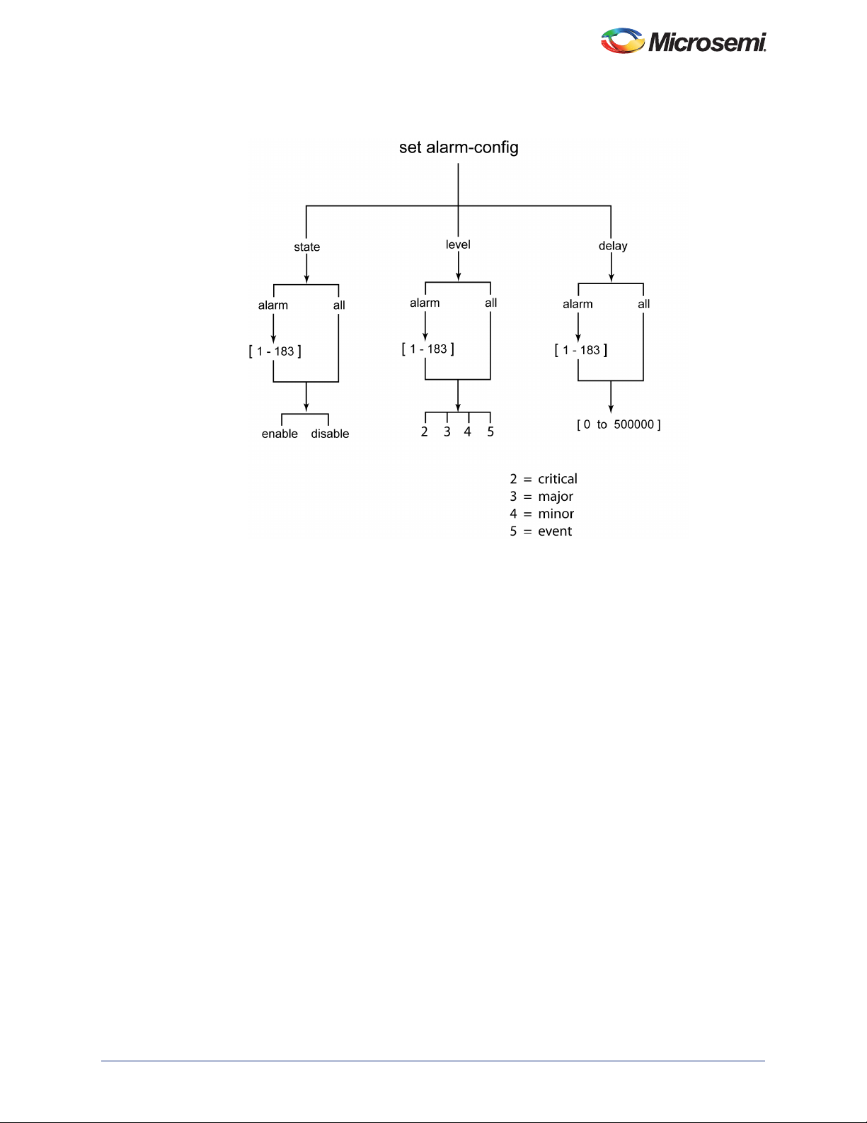
Figure 4-1 • Set Alarm-Config Command Hierarchy
SyncServer S80 NTP User Guide
Disabling Specific Alarms
The Set Alarm-Config command allows you to enable or disable specified alarms.
Example
To disable the GNSS antenna open-circuit alarm (alarm #33), enter the following:
1. Login at the Admin or Config-user level (see Logging In, on page 215).
2. Type
set alarm-config state alarm 33 disable and press Enter.
Showing Current Alarm Settings
The Show Alarm-Config command displays the set and clear alarm thresholds for every alarm type.
Example
To display the configuration for all alarm types, enter the following:
•Type
show alarm-config and press Enter.
Showing Current Alarms
The Show Alarm command displays all current alarms.
Example
To display a list of all current alarms enter the following:
•Type
show alarm and press Enter.
098-00777-000 Rev. A 55
Page 56

Configuration
Provisioning for SNMP
The Simple Network Management Protocol (SNMP) is an application layer protocol that allows you to
manage network devices. SNMP is based on a client-server query-response mode that requires an
Ethernet connection. A manager application (software installed on a computer) is the client generating
the queries, and an agent (software on the S80) is the server generating responses. The S80 SNMP
supports traps and the MIB-II system MIB.
S80 supports SNMPv2c and SNMPv3. SNMPv3 provides additional security features not available in
SNMPv2c. In addition to the functions of SNMPv2c, SNMPv3 allows user and trapuser levels that are
based on authentication and privacy settings. The authentication algorithm is either HMAC-SHA-1-96 or
MD5, with a 20-character key. The privacy settings are based on either the CBC-DES or AES encryption
standard, with a 16-character key. All keys are uppercase.
Port 161 is the port of standard SNMP interactive communications and port 162 is the trap port.
SNMP functionality is provisioned on the S80 using the CLI command “set snmp” (see Figure 4-30).
Each alarm trap OID from the S80 represents a unique alarm.
Each container contains the following sub-info in its own OID:
• Alarm/Event ID
• Date&Time
• Severity
• Alarm/Event Description
• Index
• Alarm Action
• Sequence Number
The alarm OIDs are under 1.3.6.1.4.1.9070.1.2.5.7.3.1.2.
The Alarm/Event ID element should be used to determine which alarm or event was generated. Alarm
and Event IDs are listed in Appendix A, System Messages.
Adding or Deleting a Manager IP Address
Use the “set snmp add manager” command to add a manager IP address. Use the “set snmp delete
manager” command to delete a manager IP address. The S80 will support a single manager IP address.
Example:
To add the SNMP manager IP address 192.100.100.100:
•Type
set snmp add manager 192.100.100.100 then press Enter.
Provisioning to Generate v2 Traps
Use the set snmp trapversion command to provision the trap version to v2.
By default, the S80 will generate v2 traps.
Example:
•Type set snmp trapversion 2 then press Enter.
Provisioning to Generate v3 Traps
Use the set snmp trapversion command to provision the trap version to v3.
Example
•Type set snmp trapversion 3 then press Enter.
56 098-00777-000 Rev. A
Page 57

SyncServer S80 NTP User Guide
Adding and Removing v2 Communities
Use the set snmp add v2-community command to add a SNMP v2 community. Use the set snmp delete
v2-community command to remove an existing SNMP v2 community. The S80 will support a maximum of
ten v2 communities.
Note: To use v2 communities, the v2 state must be set to Enable using the command set snmp state-v2
enable.
SNMP communities "public" and "private" are included by default and cannot be removed. If including
these communities is undesirable then using SNMPv3 alone and disabling SNMPv2 is required.
Example
To add a v2 community named “tech27”, with a security level of “read-only” and remove an existing v2
community named “bob321”:
1. Type
2. Type set snmp delete v2-community bob321 then press Enter.
set snmp add v2-community tech27 securelvl read-only then press Enter.
Adding and Removing SNMP v3 Users
SNMPv3 provides additional security features not available in SNMPv2c. In addition to the functions of
SNMPv2c, SNMPv3 allows user and trapuser levels that are based on authentication and privacy
settings. The authentication algorithm is either HMAC-SHA-1-96 or MD5, with a key of up to 32
characters in length. The privacy settings are based on either the CBC-DES or AES encryption standard,
with a key of up to 32 characters in length. All keys are uppercase.
Use the set snmp add user command to add a v3 user. Use the set snmp delete user command to
remove an existing v3 user. The S80 will support a maximum of ten v3 users.
Example - Add User
To add a user named “test12”, with a security level of “priv”, with a 20-character MD5 authentication key
“123456789ABCDEFGHIJK” and a 16-character DES privacy key “ABCDEFG123456789”:
1. Type set snmp add user test12 securelvl priv then press Enter.
2. Enter
3. Enter
4. Enter DES at the privacy protocol prompt.
5. Enter
Note: Do not use spaces within keys.
MD5 at the authentication protocol prompt.
123456789ABCDEFGHIJK at the authentication key prompt.
ABCDEFG123456789 at the privacy key prompt.
Only characters {a-z,A-Z,0-9,! ( ) - _ . ? ~ * @ ^ + = : / %} are accepted for SNMP authentication or
privacy keys.
Example - Remove User
To remove an existing user named “dave123”, type set snmp delete user dave123 then press Enter.
Adding and Removing SNMP v3 Trap Users
Use the set snmp add trapuser command to add a v3 trap user. Use the set snmp delete trapuser
command to remove an existing v3 trap user. The S80 will support a maximum of 3 v3 trap users.
Note: In order to access trap information, a trap user must also be added as a user. The same name,
authentication protocol, authentication key, privacy protocol, and privacy key must be used for both
the user and trap user.
Example - Add Trap User
To add a trap user named “test12” with a security level of “priv”, with the 20-character MD5 authentication
key “123456789ABCDEFGHIJK” and 16-character DES privacy key “ABCDEFG123456789”:
1. Type
set snmp add trapuser test12 securelvl priv then press Enter.
Enter SNMPv3 user security details :
098-00777-000 Rev. A 57
Page 58

Configuration
_________________________________________
minlevel : noauth or auth or priv
authentication : MD5 or SHA
authentication key : [Only chars {a-z, A-Z, 0-9, ! ( ) - _ . ? ~ * @ ^ + = : / %} are
accepted]
privacy protocol : DES or AES
privacy key : [Only chars {a-z, A-Z, 0-9, ! ( ) - _ . ? ~ * @ ^ + = : / %} are
accepted]
___________________________________________
Enter securitylevel: priv
user=test12, level=priv
2. Enter MD5 at the authentication protocol prompt.
Authentication protocal (MD5 or SHA) : MD5
3. Enter 123456789ABCDEFGHIJK at the authentication key prompt.
Authentication key : 123456789ABCDEFGHIJK
4. Enter DES at the privacy protocol prompt.
5. Enter
ABCDEFG123456789 at the privacy key prompt.
Example - Remove Trap User
To remove an existing trapuser named “dave123”, type set snmp delete trapuser dave123 then press
Enter.
Provisioning for LLDP
The Link Layer Discovery Protocol (LLDP) is a vendor-neutral link layer protocol in the Internet Protocol
Suite used by network devices for advertising their identity, capabilities, and neighbours on an IEEE 802
local area network, principally wired Ethernet.
LLDP information is sent by devices from each of their interfaces at a fixed interval, in the form of an
Ethernet frame. Each frame contains one LLDP Data Unit (LLDPDU). Each LLDPDU is a sequence of
type-length-value (TLV) structures.
The Ethernet frame used in LLDP has its destination MAC address typically set to a special multicast
address that 802.1D-compliant bridges do not forward. Other multicast and unicast destination
addresses are permitted. The EtherType field is set to 0x88cc.
Each LLDP frame starts with the following mandatory TLVs: Chassis ID, Port ID, and Time-to-Live. The
mandatory TLVs are followed by any number of optional TLVs. The frame ends with a special TLV,
named end of LLDPDU in which both the type and length fields are 0.
LLDP Implementation in S80
A module in the S80 sends LLDP frames every minute so that any computer connected to the LAN can
view the information of S80. This feature is useful for outdoor units where no serial connection exists to
find out IP address. The LLDP frames sent by S80 consist of following information:
• IP address
• MAC address
• System name
• System description
• Ethernet port number
A CLI command is provided to enable or disable sending LLDP frames, as shown in Examples 1 and 2
below. Another command is provided to view the current status of the LLDP module (enabled/disabled),
as shown in Example 3 below.
Example 1:
To set the LLDP state to disable -
S80> set lldp disable
58 098-00777-000 Rev. A
Page 59
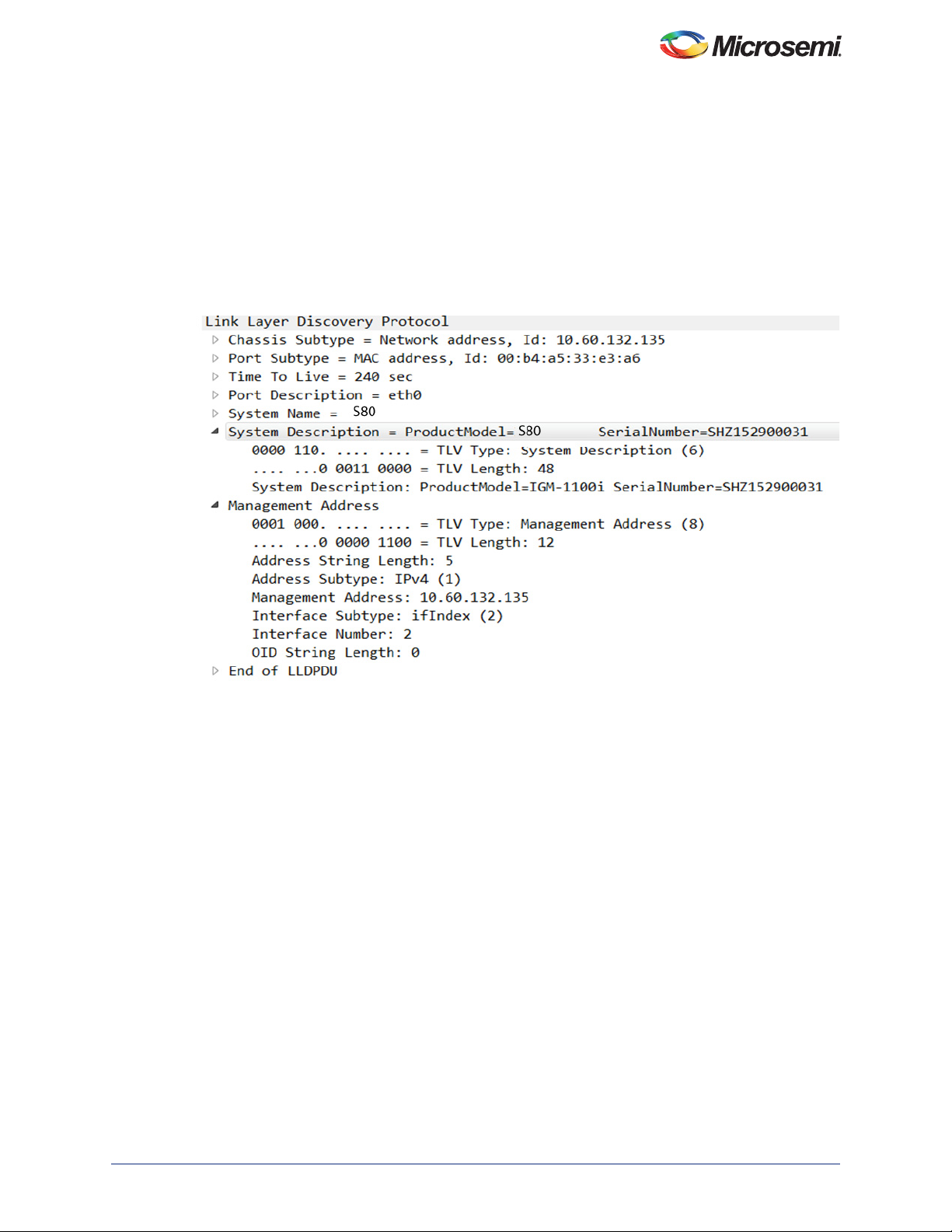
SyncServer S80 NTP User Guide
Example 2:
To set the LLDP state to enable -
S80> set lldp enable
Example 3:
S80> show lldp config
Response 3:
LLDP State : enable
Below is a screenshot from Wire Shark which shows typical LLDP frames and the information contained
in the frames..
098-00777-000 Rev. A 59
Page 60

Configuration
60 098-00777-000 Rev. A
Page 61

5 – Troubleshooting
This chapter provides troubleshooting information for the SyncServer S80.
Status of the S80 can be determined by the CLI "show status" command and SNMP trap messages. The
SNMP trap manager IP address and associated settings must be configured with the "set snmp"
command before SNMP traps are available.
System Messages
Table 5-1 • S80 System Messages
EventIDDefault
Description
Entered
time/frequency
warm-up state
Entered
time/frequency freerun state
Severity Transient Message Text Corrective Action
001 Minor No Entered time/frequency
002 Minor No Entered time/frequency
Chapter
warm-up state
Transitioned out of
warm-up state
free-run state
Transitioned out of
free-run state
No action required
No action required
No action required
No action required
Entered
time/frequency fasttrack state
Entered
time/frequency
normal-track state
Entered
time/frequency
bridging state
003 Event No Ente red time/frequency
fast-track state
Transitioned out of
fast-track state
004 Event No Ente red time/frequency
normal-track state
Transitioned out of
normal-track state
005 Event No Ente red time/frequency
bridging state
Transitioned out of
bridging state
No action required
No action required
No action required
No action required
No action required
No action required
098-00777-000 Rev. A 61
Page 62

Troubleshooting
Table 5-1 • S80 System Messages (continued)
Description
Entered
time/frequency
holdover state
EventIDDefault
Severity Transient Message Text Corrective Action
006 Minor No Entered ti me/frequency
holdover state
• Check input
references
• Check
configuration for
correct reference
selection
• Check reference
status
• Check ref
configuration for
Priority values.
Entered
time/frequency
holdover recovery
state
GNSS input
assessing
GNSS input time
qualified
GNSS input
frequency qualified
GNSS input selected
as time reference
Transitioned out of
No action required
holdover state
008 Minor No Entered ti me/frequency
No action required
holdover recovery state
Transitioned out of
No action required
holdover recovery state
021 Minor No GNSS input assessing • If this persists for >
1hr check input
reference.
• For GNSS check
signal quality.
022 Event No GNSS input time
No action required
qualified
023 Event No GNSS input frequency
No action required
qualified
Input frequency
qualified
024 Event Yes GNSS input selected
No action required
as time reference
GNSS input selected
025 Event Yes GNSS input sel as
as frequency
reference
Incompatible
051 Minor No Incompatible transport
transport type
62 098-00777-000 Rev. A
n/a
No action required
frequency reference
type
Page 63

Table 5-1 • S80 System Messages (continued)
EventIDDefault
Description
GNSS receiver
Severity Transient Message Text Corrective Action
091 Minor No GNSS receiver
communications
failed
SyncServer S80 NTP User Guide
communicationsfailed
• Reboot
• If problem persists
call SGS for
support.
GNSS receiver
communications failure
cleared
GNSS receiver not
tracking satellite
092 Minor No GNSS receiver not
tracking satellite
GNSS receiver not
tracking satellite
cleared
GNSS PPS failed 98 Event No GNSS PPS failed
GNSS Base Config
failed
Ethernet port link
99 Event No GNSS Base Config
failed
111 Minor No Ethernet port link down
down
Ethernet port link down
cleared
Excessive traffic on
port
112 Minor No Excessive traffic on
port
No action required
• Check Antenna
installation
• Check if Antenna
cable is connected
properly.
Installation should
conform to the
guidelines as
described in Ch. 2..
No action required
• Check traffic level
on network
• Check for intrusion
attempts.
• Check broadcast
traffic.
Excessive traffic
cleared on Ethernet
No action required
port
098-00777-000 Rev. A 63
Page 64

Troubleshooting
Table 5-1 • S80 System Messages (continued)
Description
PLL synthesizer
unlock
EventIDDefault
Severity Transient Message Text Corrective Action
137 Critical No PLL synthesizer unlock
• If alarm persists
power cycle/reboot
• Call SGS support if
it persists after
reboot/power cycle.
PLL unlock cleared
Temperature out of
range
Time Line has been
Changed
Phase Has Been
Aligned
System reboot 155 Event No System reboot n/a
Ethernet Speed 156 Event No Ethernet Speed
GNSS Acquisition
status Changed
NTP Stratum
Change
139 Minor No Temperature out of
range
Temperature out of
range cleared
152 Event Yes Time Line has been
Changed
n/a
153 Event Yes Phase Has Been
Aligned
n/a
157 Event No GNSS Acquisition
status Changed
179 Event No NTP Stratum Change
No action required
Check your operating
environment.
No action required
n/a
n/a
n/a
n/a
NTP Leap Change 180 Event No NTP Leap Change
NTP Passive Mode 181 Event NTP Passive Mode
NTP Active Mode 182 Event NTP Active Mode
NTP Service Load
Limit
183 Event NTP Service Load
Limit
Recovering Lost IP Address with LLDP Utility
The LLDP feature, which is enabled by default, provides a way for the user to discover the management
port IP address of the unit since there is no serial port connection available. When the LLDP state is
enabled, LLDP frames are sent out by the S80 every minute. The LLDP frames sent by S80 consist of
information about Management port IP address, MAC address, System name, System description, and
Ethernet port number. Any computer connected in LAN or back-to-back can know these details of the
S80 by capturing these LLDP frames using network packet analyzer software, such as Wireshark.
64 098-00777-000 Rev. A
Page 65
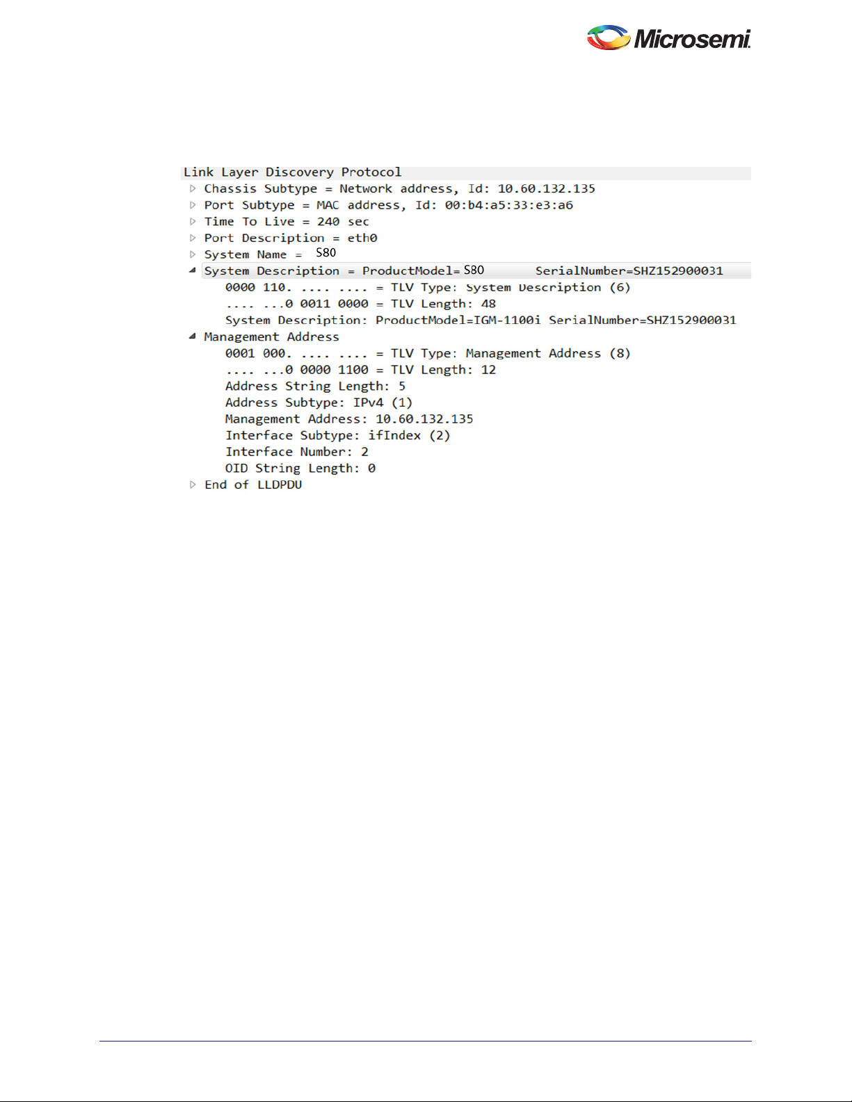
SyncServer S80 NTP User Guide
Figure 5-1 show a typical captured LLDP frame, from which the IP address can be recovered.
Figure 5-1 • LLDP Frame Captured by Network Pack Analyzer..
Returning the SyncServer S80
You should return the equipment to Microsemi only after you have exhausted the troubleshooting
procedures described earlier in this chapter and Microsemi FTD Services and Support has advised you
to return the unit.
Note: Please retain the original packaging for re-shipping the product. If the original packaging is not
available, contact Microsemi FTD Services and Support for assistance.
Repacking the Unit
Return all units in the original packaging. If the original packaging is not
available, contact Microsemi FTD Services and Support. Use standard
packing procedures for products being returned for repair to protect the
equipment during shipment. Connectors should be protected with connector
covers or the equipment should be wrapped in plastic before packaging.
Equipment Return Procedure
To return equipment to Microsemi for repair:
1. Call Microsemi FTD Services and Support at 888-367-7966 (toll-free in
USA only), 408-428-7907, or +49 700 3288 6435 in Europe, Middle East,
098-00777-000 Rev. A 65
Page 66

Troubleshooting
or Africa to obtain a return material authorization number (RMA) before
returning the product for service.
You can request an RMA on the internet at
www.microsemi.com/ftdsupport
Retain the assigned RMA number for future reference.
2. Provide a description of the problem, product item number, serial number,
and warranty expiration date.
3. Provide the return shipping information (customer field contact, address,
telephone number, and so forth.)
4. Ship the product to Microsemi, transportation prepaid and insured, with
the Return Material Authorization (RMA) number and item numbers or
part numbers clearly marked on the outside of the container to the
address given with the RMA.
Repaired equipment is returned to you with shipping costs prepaid by
Microsemi.
User’s Guide Updates
When this manual is updated the updated version will be available for
downloading from Microsemi’s internet web site. Manuals are provided in
PDF format for ease of use. After downloading, you can view the manual on
a computer or print it using Adobe Acrobat Reader.
Manual updates are available at:
www.microsemi.com/ftdsupport
Note: If you are downloading a product manual for the first time, you will need to register with Microsemi
for a username and password. If you are currently registered, login and download the manual
update.
Contacting Technical Support
See "Product Support" on page 73 for details about contact information.
66 098-00777-000 Rev. A
Page 67
Appendix A – Specifications and Factory Defaults
This chapter describes the specifications and factory defaults for the SyncServer S80.
Specifications
Mechanical
Table A-1 • Mechanical Specifications
Parameter Specification
Mounting Roof
Diameter 6.0 inches (15.24 cm)
Height 6.0 inches (15.24 cm)
Weight 1.5 lbs. (0.68 kg)
Environmental
Table A-2 • Environmental Specification
Parameter Specification
Operating Temperature -40
Storage Temperature -40
Transportation Temperature -40
Operating Humidity 5 to 100%, with condensation
to 70 C
to 85 C
to 85 C
Power
Table A-3 • Power Specification
Parameter Specification
Input Class PoE Class 3 input
Power Consumption < 12.5 Watts
098-00777-000 Rev. A 67
Page 68

Compliance & Certifications
Table A-4 • Compliance Specifications and Certifications
Parameter Specification
Safety Certifications UL60950-1/CSA C22.2,
IEC60950- 1:2005(2nded)/AM 1:2009/AM 2:2013,
EN60950-1: 2ed. 2006/A11:2009/A1:2010/A12:2011/A2:2013
EMC Compliance • EN 300386 v1.6.1;
• CISPR 32: 2102, Class B limits;
• CISPR 24: 2010;
• EN 55032: 2012/AC2013, Class B limits;
• EN 55024: 2010;
• FCC Title 47 Part 15, ICES-003, AS/NZS, Class B limits;
• VCCI V-3/2015.04/V-4/2012.04, Class B limits;
• KN 55032/35, Class B limits
• K.20;BSMI
EMC Certifications • EMC Directive 2014/30/EU Class B,
• FCC part 15,
• ICES-003,
• VCCI,
• AS/NZS
• CISPR 22,
• ETSI, EN 55022/EN55024,
• KN55032/KN55035,
• BSMI
Environmental • ETSI 300 019-2-1 Storage Tests Class T1.2
• ETSI 300 019-2-2 Transportation Tests Class T2.3
• ETSI 300 019-2-4 Operational Tests Class T4.1E
• 6.1 Salt Fog Exposure
• 6.2.2 Seismic under GR-63 and ANSI T1-329
• RoHS 2 Directive 2011/65/EU
• WEEE Directive 2012/19/EU
• IEC 60529 Ed. 2.2 2013, IP66 Compliant
Clock Performance
The S80 clock system is compatible with a Type I Clock as defined in G.812.
Table A-5 • Clock Performance Specification
Parameter Specification
Oscillator Type DOCXO ( Double Ovenized OCXO)
Temperature Stability <2 ppb
Steady State Aging Rate 0.2 ppb per day
68 098-00777-000 Rev. A
Page 69

SyncServer S80 NTP User Guide
Table A-5 • Clock Performance Specification
Parameter Specification
Accuracy <100 ns to UTC (locked GPS with full sky view)
Holdover 400 microseconds per day
Inputs
Table A-6 • Input Specification
Parameter Specification
GNSS • 72-channel GPS/GLONASS receiver, time traceable to UTC
• <100 nanoseconds RMS to UTC (USNO)
• Operational modes
– Static: Fixed location, non-moving
–Dynamic:
Automotive (altitude 6000 m, speed 60 miles/hour)
Sea (altitude 500 m, speed 45 miles/hour)
Outputs
Table A-7 • Output Specification
Parameter Specification
NTP • NTP v3/v4 mode 3 NTP client time requests
• 500 NTP requests per second, optionally 1000 NTP requests per
second.
• Stratum 1 through GPS: Overall server time stamp accuracy of
<100 nanoseconds RMS to UTC (USNO).
• All NTP time stamps are hardware-based and have real-time
hardware compensation for internal asymmetric delays. The
accuracy is measured at the network interface. NTP is UTC
timescale by definition.
• All non-NTP packets are provided to the CPU on a filtered,
bandwidth-limited basis.
098-00777-000 Rev. A 69
Page 70
Factory Defaults
Management IP Parameters
Table A-8 • Management IP Parameters
Parameter Value Default Value Range
IPv4 State enable enable | disable | restart
IPv6 State enable enable | disable | restart
Address Mode Static | DHCP
IPv4 Network Address 192.168.2.100 Valid IPv4 address
IPv4 Network Mask 255.255.255.0 Valid IPv4 mask
IPv4 Network Gateway 192.168.2.1 Valid IPv4 Address, where value of
IPv6 Network Address Valid IPv6 address
IPv6 Network Mask (Prefix) 64
IPv6 Network Gateway Valid IPv6 Address
0.0.0.0 is used for no gateway
GNSS Parameters
Table A-9 • GNSS Parameters
Parameter Value Default Value Range
Stat e
Cable Delay
Elevation Mask
Clock Parameters
Table A-10 • Clock Parameters
Parameter Value Default Value Range
Leapseconds
enable enable | disable
0 0 - 9999 (ns)
55 - 60
36 20 - 255
70 098-00777-000 Rev. A
Page 71
SyncServer S80 NTP User Guide
NTP Parameters
Table A-11 • SNMP Parameters
Parameter Value Default Value Range
State enable enable | disable
NTPr IP Mode IPv4 IPv4 | IPv6
TTL 64 1 to 255
DSCP 46 0 to 63
Alarm Threshold (percentage) 100 1 to 100
SNMP Parameters
Table A-12 • SNMP Parameters
Parameter Value Default Value Range
Trap Manager IPv4 0.0.0.0 Up to 15 character IPV4 address
string
Trap Version 2 2 | 3
V2 Trap Commnunity public Up to 19 character string
V3 Secure Level noauth 0 | 1 | 2
0=noauth
1=auth
2=priv
V3 Auth Pass password 8 to 31 characters string
V3 Auth Algorithm MD5 1 | 2
1=MD5
2=SHA
V3 Priv Pass password 8 to 31 characters string
V3 Priv Algorithm DES 1 | 2
1=DES
2=AES
Network Address 0.0.0.0 Valid IPv4 address
Network Mask 255.255.255.0 Valid IPv4 mask
Network Gateway 0.0.0.0 Valid IPv4 Address, where value of
0.0.0.0 is used for no gateway
098-00777-000 Rev. A 71
Page 72
Log Configuration Parameters
Table A-13 • Log Configuration Parameters
Parameter Value Default Value Range
Size for Alarm-Event Log (kb) 100 1 to 100
Size for Command Log (kb) 100 1 to 100
Size for Security Log (kb) 100 1 to 100
72 098-00777-000 Rev. A
Page 73

Appendix B – Product Support
Microsemi Timing & Frequency Services backs its products with various support services, including
Customer Service and Technical Support through the Customer Assistance Center, a website, electronic
mail, and worldwide sales offices. This appendix contains information about contacting Microsemi Timing
& Frequency Services and using these support services.
Customer Service
Contact Customer Service for non-technical product support, such as product pricing, product upgrades,
update information, order status, and authorization.
• Worldwide (Main Number): 1-408-428-7907
• USA toll-free: 1-888-367-7966
• USA, Canada, Latin America including Caribbean, Pacific Rim including Asia, Australia and New
Zealand: 1-408-428-7907
• Europe, Middle East & Africa: 49 700 3288 6435 or 49 8102 896 1535
Customer Assistance Center
Microsemi Timing & Frequency Services staffs its Customer Assistance Center with highly skilled
engineers who can help answer your hardware, software, and design questions about Microsemi Timing
& Frequency Services products. The Customer Assistance Center spends a great deal of time creating
application notes, answers to common design cycle questions, documentation of known issues, and
various FAQs. So, before you contact us, please visit our online resources. It is very likely we have
already answered your questions.
Technical Support
Visit the Customer Support website (www.microsemi.com/ftdsupport) for more information and support.
Many answers available on the searchable web resource include diagrams, illustrations, and links to
other resources on the website.
Website
You can browse a variety of technical and non-technical information on the Microsemi Timing &
Frequency Services home page, at www.microsemi.com/ftdsupport.
Contacting the Customer Assistance Center
Highly skilled engineers staff the Customer Assistance Center. The Customer Assistance Center can be
contacted by email or through the Microsemi Timing & Frequency Services website.
You can communicate your technical questions to our email address and receive answers back by email,
fax, or phone. Also, if you have design problems, you can email your design files to receive assistance.
We constantly monitor the email account throughout the day. When sending your request to us, please
be sure to include your full name, company name, and your contact information for efficient processing of
your request.
The technical support email address is [email protected].
098-00777-000 Rev. A 73
Page 74

Outside the U.S.
Customers needing assistance in Europe, the Middle East, or Africa (EMEA) can either contact technical
support via email ([email protected]) or contact a local sales office. Sales office listings
can be found at http://www.microsemi.com/salescontacts.
Microsemi Corporate Headquarters
One Enterprise, Aliso Viejo CA 92656 USA
Within the USA: +1 (800) 713-4113
Outside the USA: +1 (949) 380-6100
Sales: +1 (949) 380-6136
Fax: +1 (949) 215-4996
E-mail: [email protected]
Microsemi Corporation (Nasdaq: MSCC) offers a comprehensive portfolio of semiconductor
and system solutions for communications, defense and security, aerospace, and industrial
markets. Products include high-performance and radiation-hardened analog mixed-signal
integrated circuits, FPGAs, SoCs, and ASICs; power management products; timing and
synchronization devices and precise time solutions, setting the world's standard for time; voice
processing devices; RF solutions; discrete components; security technologies and scalable
anti-tamper products; Power-over-Ethernet ICs and midspans; as well as custom design
capabilities and services. Microsemi is headquartered in Aliso Viejo, Calif. and has
approximately 3,400 employees globally. Learn more at www.microsemi.com.
© 2017 Microsemi Corporation. All rights reserved. Microsemi and the Microsemi logo are trademarks of
Microsemi Corporation. All other trademarks and service marks are the property of their respective owners.
098-00777-000 Rev. A / 11.17
 Loading...