

Page 1
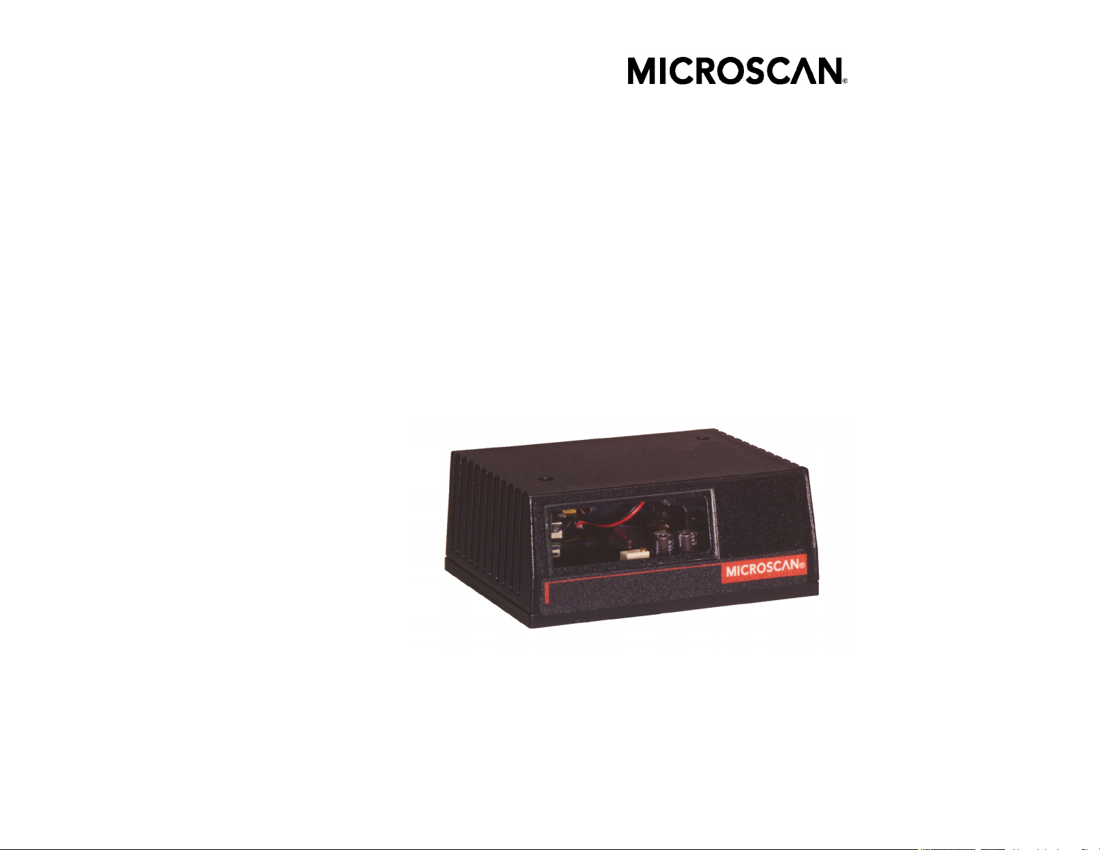
MS-810
Industrial Scanner
User's Manual
P/N 83-000810 Rev B
Page 2

Copyright © 2000
by Microscan Systems, Inc.,
1201 S.W. 7th Street, Renton, Washington, U.S.A. 98055
(425) 226-5700 FAX: (425) 226-8682
ISO 9001/Certification No. US96/0465
All rights reserved. The information contained herein is proprietary and is provided solely for the
purpose of allowing customers to operate and/or service Microscan manufactured equipment
and is not to be released, reproduced, or used for any other purpose without written permission
of Microscan.
Throughout this manual, trademarked names might be used. Rather than put a trademark (™) symbol in every occurrence of a trademarked name, we state herein that we
are using the names only in an editorial fashion, and to the benefit of the trademark
owner, with no intention of infringement.
Warranty Information
Microscan Systems, Inc. warrants products manufactured by it to be free from defects in
material or workmanship under normal use and service for a period of one year from
date of shipment.
This warranty is specifically limited to the replacement or repair of any such warrantable
defects, without charge, when the complete product is returned to Microscan Systems,
Inc., freight prepaid, at the address shown above. Contact the factory at the address
above for a Return Material Authorization (RMA) number before returning the product.
Microscan Systems, Inc. shall be the sole judge of the warrantability of alleged product
defects. Products that are returned for warranty examination and that are found to be
non-warrantable are chargeable and are returned freight collect. A copy of a purchase
order with the amount of the charge must be received by Microscan, either by mail or by
FAX, before any equipment is returned. Warrantable products are repaired or replaced at
no charge and returned freight prepaid.
THIS EXPRESS WARRANTY EXCLUDES ALL OTHER WARRANTIES, EXPRESS OR IMPLIED,
INCLUDING, BUT NOT LIMITED TO, IMPLIED WARRANTIES OF MERCHANTABILITY AND
FITNESS FOR PURPOSE. MICROSCAN SYSTEMS, INC., SHALL NOT BE LIABLE FOR WARRANTY IN ANY AMOUNT EXCEEDING THE PURCHASE PRICE OF THE GOODS. MICROSCAN
SYSTEMS, INC., SHALL NOT BE LIABLE FOR ANY SPECIAL, INCIDENTAL, OR CONSEQUENTIAL DAMAGES, WHETHER IN CONTRACT, TORT, OR OTHERWISE.
The buyer acknowledges that he/she is not relying on the seller's skill or judgment to select or
furnish goods suitable for any particular purpose and that there are no warranties that extend
beyond the description on the face hereof.
This warranty extends only to the original purchaser, and shall not apply to any products
or parts that have been subject to misuse, neglect, accident, or abnormal conditions or
operations. Claims for damage in transit are directed to the freight carrier upon receipt.
Disclaimer
The information and specifications described in this manual are subject to change without
notice.
For the latest version of this manual, see the Download page on our web site at
www.microscan.com
. For technical support email
iv MS-810 Scanner User’s Manual
Page 3

Table of Contents
List of Illustrations ......................................................................................v
List of Tables ............................................................................................ vi
About the MS-810 Scanner ..................................................................... vii
About This Manual ................................................................................... vii
Keystroke Entries .................................................................................... vii
Approvals .................................................................................................viii
Warning and Caution Summary ..............................................................viii
Zulassungen ............................................................................................. ix
Sicherheitshinweis und Vorsichtsmaßnahmen......................................... ix
Safety Labels ............................................................................................ xi
Chapter 1, Setup and Installation
Step 1 - Plan Scanning System ..............................................................1-2
Step 2 - Attach Cabling ...........................................................................1-3
Step 3 - Consider Read Range and Scan Width ....................................1-4
Step 4 - Position Scanner .......................................................................1-5
Step 5 - Mount Scanner ..........................................................................1-6
Step 6 - Establish Communications ........................................................1-7
Step 7 - Configure Scanner .................................................................... 1-8
Step 8 - Test Decode Rate with Static Label .......................................... 1-9
Step 9 - Test Decode Rate with Moving Label .....................................1-10
Step 10 - Increase the Number of Scans ............................................. 1-11
Chapter 2, Menu Configuration
About the Menu Configuration Program..................................................2-2
Communications Menu............................................................................2-5
Protocol Menu ....................................................................................... 2-12
Operation Menu..................................................................................... 2-16
Code Type Menu................................................................................... 2-25
Output Menu ......................................................................................... 2-32
Setup Menu ...........................................................................................2-38
Chapter 3, Serial Configuration
About Serial Configuration ...................................................................... 3-3
Communications Port Commands ..........................................................3-5
Protocol Commands ...............................................................................3-6
Operations Commands .........................................................................3-10
Code Types Commands .......................................................................3-13
Scanner Output Commands ................................................................. 3-16
Scanner Setup Commands ..................................................................3-19
MS-810 Scanner User’s Manual v
Page 4

Chapter 4, Operational Commands
Read Rate............................................................................................... 4-3
Trigger..................................................................................................... 4-5
Scanner................................................................................................... 4-6
Counters.................................................................................................. 4-7
Master Label ........................................................................................... 4-9
Reset..................................................................................................... 4-11
Checksum ............................................................................................. 4-13
Code Type Commands ......................................................................... 4-15
Appendices
Appendix A — Scanner Specifications ...................................................A-2
Appendix B — Electrical Specifications ................................................. A-4
Appendix C — Ground and Shield Considerations ...................................... A-9
Appendix D — ASCII Table ..................................................................A-10
Appendix E — Transferring/Restoring Files .........................................A-11
Appendix F — IB-130 Interface Module ...............................................A-13
Appendix G — Number of Scans .........................................................A-18
Appendix H — Special 5 VDC MS-810 ................................................A-21
Appendix I — Using the IB-105 ............................................................A-22
Appendix J — Troubleshooting ............................................................ A-28
Appendix K — Bar Code Symbology ................................................... A-31
Appendix L — Interface Standards ......................................................A-32
Appendix M — Multidrop Communications ................................................ A-33
Appendix N — Glossary of Terms ........................................................A-36
Index I-1
List of Illustrations
Figure 1-1 Typical Setup ........................................................................ 1-2
Figure 1-2 DTE Host Connection ........................................................... 1-3
Figure 1-3 MS-810 15-pin Connector ..................................................... 1-3
Figure 1-4 Read Range and Width ........................................................ 1-4
Figure 1-5 Tilt, Skew, and Pitch Axes .................................................... 1-5
Figure 1-6 MS-810 Mounting Dimensions .............................................. 1-6
Figure 2-1 Configuration Program - Main Menu ..................................... 2-2
Figure 2-2 Communications Menu Structure ......................................... 2-5
Figure 2-3 Protocol ............................................................................... 2-12
Figure 2-4 Operation Menu Structure .................................................. 2-16
Figure 2-5 External Level Trigger Signals ............................................ 2-17
Figure 2-6 External Edge Trigger Signals ............................................ 2-18
Figure 2-7
Figure 2-8 Code Types Menu Structure ............................................... 2-25
vi MS-810 Scanner User’s Manual
Match Code Type ......................................................2-22
Page 5

Figure 2-9 Scanner Output Menu Structure .........................................2-33
Figure 2-10 Setup Menu Structure .......................................................2-39
Figure A-1 MS-810 Dimensions .............................................................A-2
Figure A-2 15-pin High-density D-subminiature plug ..............................A-4
Figure A-3 Grounding Diagram, Scanner-Host ......................................A-9
Figure A-4 Ladder Orientation ..............................................................A-18
Figure A-5 Picket Fence Orientation ....................................................A-18
Figure A-7 Label Dimensions ...............................................................A-19
Figure A-6 Angled Picket Fence Orientation ........................................A-19
Figure A-8 5 Volt Setup with Auxiliary Monitor .....................................A-21
Figure A-8 15-pin Connector ................................................................A-21
Figure A-9 Front of IB-105 ....................................................................A-22
Figure A-10 Back of IB-105 ..................................................................A-22
Figure A-11 Select Sequence ..............................................................A-34
List of Tables
Table 2-1 Symbology Identifier Option Values .....................................2-31
Table 3-1 Summary of Serial Configuration Commands ........................3-2
Table 3-2 Protocol Commands ...............................................................3-8
Table 4-3 Hex Value to Binary Conversion ..........................................4-13
Table 4-4 Finding Scanner Status from Binary Bit Digits ..................... 4-14
Table A-1 Range Data ............................................................................A-3
Table A-2 FIS Options ............................................................................A-3
Table A-3 10 to 28 VDC Pinouts for Standard Options ..........................A-4
Table A-4 ASCII Table with Control Characters ...................................A-10
Table A-5 Connector for 5 V Special Only ............................................A-21
Table A-6 IB-105 Trigger Connector ....................................................A-23
Table A-7 IB-105 Scanner Connector ..................................................A-23
Table A-8 IB-105 Power Connector ......................................................A-23
Table A-9 IB-105 D-sub Host Connector ..............................................A-23
Table A-10 IB-105 LAN (RJ11) Connector ...........................................A-24
Table A-11 IB-105 Options ...................................................................A-24
Table A-12 Multidrop Address Characters ...........................................A-35
MS-810 Scanner User’s Manual vii
Page 6

About the MS-810 Scanner
The MS-810 is a programmable, fixed-mount, high-speed scanner that reads and
decodes a wide variety of bar code labels using a 10-sided spinning mirror to project
laser beams over a wide scan angle.
About This Manual
This manual provides complete information on setting up and installing the MS-810
scanner.
Chapter 1 helps you to quickly setup start using your system. It includes “go to” references to other chapters and appendices for more extensive information.
Chapter 2 introduces you to the Easy Setup Program (ESP) and describes the configuration commands.
Chapter 3 lists serial commands for configuring the MS-810 scanner.
Chapter 4 lists serial commands that can be used for operations.
For specifications, see appendix A. The appendices also include reference tables, as
well as other useful information relating to bar coding and the MS-810 scanner.
Keystroke Entries
Keystrokes to be entered from your terminal are highlighted, as in <P>.
Serial commands and operational commands are enclosed in angle brackets (<>).
viii MS-810 Scanner User’s Manual
Page 7

Approvals
This equipment is designed for approval or compliance by the following organizations:
• CDRH (Center for Devices & Radiological Health)
• UL (Underwriters Laboratories, Inc.)
• cUL (UL mark of Canada)
• TüV (Technischer überwachungs-Verein)
• FCC (Federal Communication Commission)
•CE Compliant
Warning and Caution Summary
This equipment has been tested and found to comply with the limits for a Class A
digital device, pursuant to part 15 of the FCC Rules. These limits are designed to
provide reasonable protection against harmful interference in a residential installation. This equipment generates, uses, and can radiate radio frequency energy, and,
if not installed and used in accordance with the instructions, may cause harmful
interference to radio communications. However, there is no guarantee that interference will not occur in a particular installation. If this equipment does cause harmful
interference to radio or television reception, which can be determined by turning the
equipment off and on, the user is encouraged to try to correct the interference by
one or more of the following measures:
• Reorient or relocate the receiving antenna
• Increase the separation between the equipment and receiver
• Connect the equipment into an outlet on a circuit different from that to which the
receiver is connected
• Consult the dealer or an experienced radio/TV technician for help
This appliance can only be connected to a VDE approved power supply with a rating
voltage between 10 V DC and 28 V DC. The SELV power supply must be rated at
least 6,5 W at the output to avoid any hazard.
European models must use a similarly rated Class I or Class II power supply that is
certified to comply with standard for safety EN 60950.
MS-810 Scanner User’s Manual ix
Page 8
WARNING
Use of controls, adjustments, or performance of procedures other than
those specified herein may result in hazardous laser light radiation
exposure.
WARNING
There are no user serviceable parts in the MS-810 scanner. Opening
the scan head voids the Microscan Systems warranty and could
expose the user to laser diode power of up to 7 mW.
WARNING
The laser beam can be harmful to eyesight. Avoid eye contact with the
laser beam. Never point the beam at other people, or in a direction
where people may be passing.
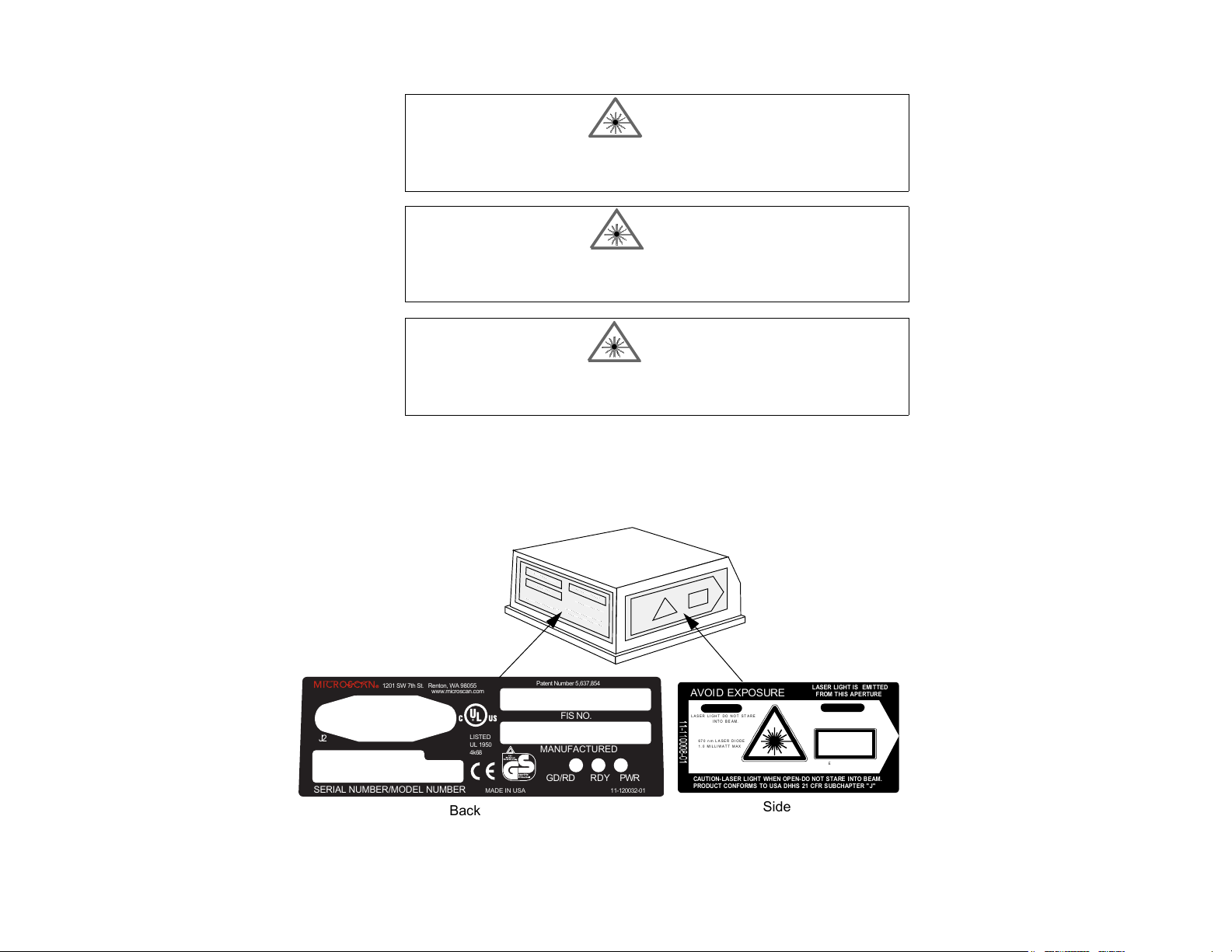
Safety Labels
These Class II labels are located on the MS-810 scanner.
1201 SW 7th St. Renton, WA 98055
J2
SERIAL NUMBER/MODEL NUMBER
www.microscan.com
LISTED
UL 1950
4k68
MADE IN USA
Patent Number 5,637,854
FIS NO.
MANUFACTURED
RDY PWR
GD/RD
11-120032-01
Back
x MS-810 Scanner User’s Manual
LASER LIGHT IS EMI TTED
AVOID EXPOSURE
CAUTI ON
LASER LIGHT DO NOT STARE
INTO BEAM.
670 nm LA SER DIODE
1.0 MILLIWAT T MAX
CLASS II LASER PRODUCT
CAUTION-LASER LIGHT WHEN OPEN-DO NOT STARE INTO BEAM.
PRODUCT CONFORMS TO USA DHHS 21 CFR SUBCHAPTER "J"
FROM THIS APERTURE
VORS I CHT
LASERSTRAHLUNG, WENN ABDECKUNG
GEÖF FNET. NICHT IN DEN S TRAHL BL ICKEN
LASERSTRAHLUNG NI CHT IN
DEN STRAHL BLI CKEN
LASER KLASSE 2
nJ @ 38uS
EN 60825-1: 1994
DIN VDE 0837 Teil 1: 1994-07
Side
Page 9

Zulassungen
Dieses Gerät wurde für die Zulassung durch die folgenden Organisationen
und in Übereinstimmung mit deren Normen entwickelt:
CDRH (Center for Devices & Radiological Health; Zentrum für Geräte und Strahlenschutz)
UL (Underwriters Laboratories, Inc.)
cUL (kanadisches UL-Zeichen)
TüV (Technischer Überwachungsverein)
FCC (Federal Communication Commission; Kommunikationsausschuß der USA)
CE konform
Sicherheitshinweis und Vorsichtsmaßnahmen
Diese Gerät wurde geprüft und entspricht den Grenzwerten für ein digitales Gerät
der Klasse A gemäß Teil 15 der FCC-Richtlinien. Diese Grenzwerte bieten ausreichenden Schutz vor schädlichen Störungen bei einer Installation in Wohnräumen.
Dieses Gerät kann Hochfrequenzstrahlung erzeugen, verwenden und abgeben. Wenn
es nicht den Anleitungen entsprechend installiert und verwendet wird, kann es zu
Funkstörungen kommen. Es gibt jedoch keine Garantie, daß bei bestimmten Installationen keine Störungen auftreten. Sie können feststellen, ob dieses Gerät den
Funk- oder Fernsehempfang beeinträchtigt, indem Sie es ein- und ausschalten. Versuchen Sie in diesem Fall, die Störung mit Hilfe einer der folgenden Methoden zu
beheben:
• Richten Sie die Empfangsantenne anders aus, oder wählen Sie einen anderen Standort.
• Erhöhen Sie den Abstand zwischen diesem Gerät und dem Empfangsgerät.
• Schließen Sie dieses Gerät an eine Steckdose eines anderen Stromkreises als dem
des Empfangsgerätes an.
• Setzen Sie sich mit dem Händler oder einem erfahrenen Funk- und Fernsehtechniker
in Verbindung.
Dieses Gerät darf nur an eine VDE geprüfte Spannungsversorgung mit 10V
28V
angeschlossen werden. Die SELV Spannungsversorgung muß mindestens 6,5
···
W am Ausgang liefern, um Gefahren zu vermeiden.
Modelle für den europäischen Markt müssen eine entsprechende Stromversorgung
der Klasse I oder II verwenden, die nach der Sicherheitsrichtlinie EN 60950 zertifiziert ist.
···
bis
MS-810 Scanner User’s Manual xi
Page 10
Te c h n i s c h e D a t e n
Eingangsspannung:10 - 28 V …
Eingangsleistung:6,5 W
Betriebsart:Dauerbetrieb
Schutzklasse:III
Anschlußart:Es muß eine nach EN60950 geprüfte SELV Spannungsversorgung ver-
wendet werden, die den entsprechenden Eingangsparametern dieses Bar Code
Scanner entspricht.
Dieses Gerät wird an eine spezielle Einrichtung angeschlossen. Der Installateur muß
sicherstellen, daß die Spannungsversorgung einen SELV Ausgang im Sinne der zutreffenden VDE Bestimmungen besitzt und die Ausgangsdaten mit den Eingangsdaten
des Bar Code Scanners übereinstimmen, um ein Überhitzen oder andere Gefahren
zu vermeiden.
Dieses Gerät ist nur für kommerzielle Zwecke und nicht den Benutzer (im Sinne der
VDE-Bestimmungen) vorgesehen und darf nur von besonders geschultem Personal
eingebaut werden. Es ist kein Einzelgerät und die Person, die den Einbau oder evt.
notwendige Optimierungen am Bar Code Scanner vornimmt, muß der englischen
Sprache mächtig sein und sollte fachkundigen Rat beim Hersteller oder Importeur
einholen. Sollten Sie Fragen haben, kontaktieren Sie bitte Microscan Systems Inc.
USA oder den entsprechenden europäischen Vertreter in Ihrem Land.
Achtung/Warnung:
WARNUNG
Die Verwendung von Steuerelementen, Anpassungen oder das Ausführen von Prozeduren, die von den hier beschriebenen abweichen, kann
dazu führen, daß Sie gefährlichen Laserstrahlen ausgesetzt werden.
WARNUNG
Der Scanner MS-810 enthält keine Teile, die durch den Benutzer
gewartet werden können. Durch Öffnen des Abtastkopfes wird die
Gewährleistung von Microscan Systems nichtig. Außerdem können
Sie einer Laserdiodenleistung von bis zu 7 mW ausgesetzt werden.
WARNUNG
Der Laserstrahl kann Ihre Augen schädigen. Vermeiden Sie direkten
Blickkontakt mit dem Laserstrahl. Richten Sie den Strahl niemals auf
anwesende Personen oder dorthin, wo möglicherweise Personen vorbei kommen könnten.
xii MS-810 Scanner User’s Manual
Page 11

Chapter
1
1–Quick Start
Quick Start
Chapter Contents
Step 1 - Plan Scanning System ..............................................................1-2
Step 2 - Attach Cabling ...........................................................................1-3
Step 3 - Consider Read Range and Scan Width ....................................1-4
Step 4 - Position Scanner .......................................................................1-5
Step 5 - Mount Scanner ..........................................................................1-6
Step 6 - Establish Communications ........................................................1-7
Step 7 - Configure Scanner .................................................................... 1-8
Step 8 - Test Decode Rate with Static Label .......................................... 1-9
Step 9 - Test Decode Rate with Moving Label .....................................1-10
Step 10 - Increase the Number of Scans ............................................. 1-11
This chapter provides step-by-step instructions for setting up and installing the
MS-810 scanner.
Note: Bar code labels should meet minimum ANSI (American National Standards
Institute) standards as specified in ANSI Bar Code Print Quality Guideline, X3.182-
1990.
MS-810 Industrial Scanner User’s Manual
1-1
Page 12
Chapter 1
Step 1 Plan Scanning System
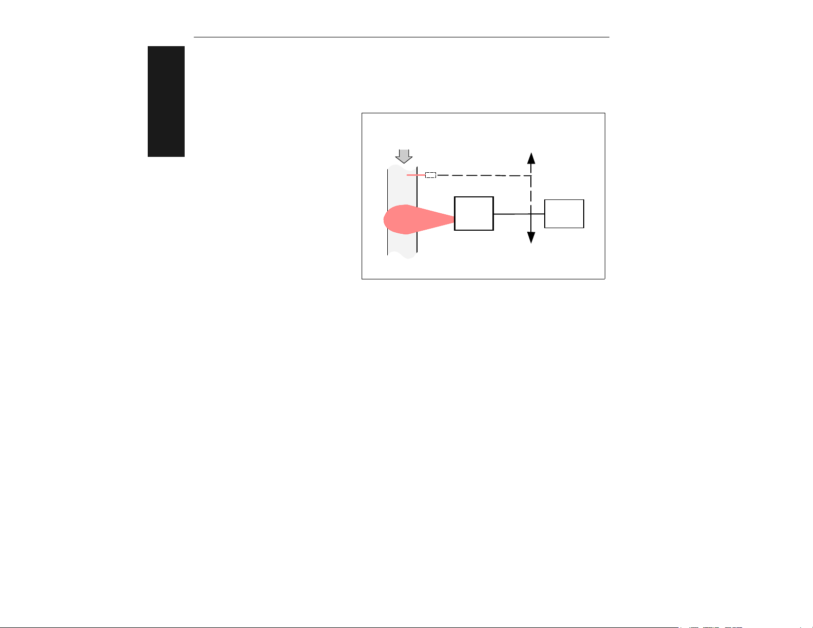
Before installing the MS-810
scanner you should sketch out
1–Quick Start
a diagram of your scanning
system, showing equipment,
connector and cable types, and
cable lengths. (For wiring information, see “Attach Cabling”
on page 1-3.) Figure 1-1
shows a typical scanning system setup.
Bar-coded
item flow
2 outputs from
internal relays
External Object
Detector
MS-810
Scanner
To power supply
Figure 1-1 Typical Setup
Host
1-2
MS-810 Industrial Scanner User’s Manual
Page 13
Step 2 Attach Cabling
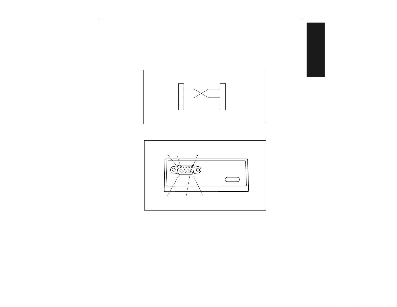
The MS-810 has a 15-pin connector. RS-232 cabling from the 15-pin connector to the host
can be up to 47 feet provided it does not include DC input.
1–Quick Start
Transmit
Receive
Signal
Ground
Scanner
2
3
4
Host
2
3
Transmit
Receive
Signal
Ground
Figure 1-2 DTE Host Connection
11
1
6
10
5
15
Figure 1-3 MS-810 15-pin Connector
Note: Pinouts are shown in Appendix B — “Electrical Specifications” on page
A-4 and in “Special 5 VDC MS-810” on page A-21.
MS-810 Industrial Scanner User’s Manual
1-3
Page 14
Chapter 1
Step 3 Consider Read Range and Scan Width
a) Verify that the labels to be scanned will pass through the readable range. Opti-
1–Quick Start
mum decode rates can be expected at the center of the depth of field (halfway
between minimum and maximum read range) for a given bar code density.
b) Note the approximate scan width at the specific distance the labels will be pass-
ing through.
Read range is the distance from the scanner in which a passing label can be read.
For the MS-810, read range varies from 2 to 30 inches depending on label density
and optical version of scanner.
Scan width is that distance across the scan arc in which a label can be read. For a
moving label, the closer to the scanner, the shorter the time it will be within the
scan width, and hence the fewer scans it will receive.
Figure 1-4 Read Range and Width
Note: See Table A-1, “Range Data,” on page A-3.
1-4
MS-810 Industrial Scanner User’s Manual
Page 15
Step 4 Position Scanner
a) Position the scanner in a place devoid of sunlight, bright lights, or laser light from
other sources.
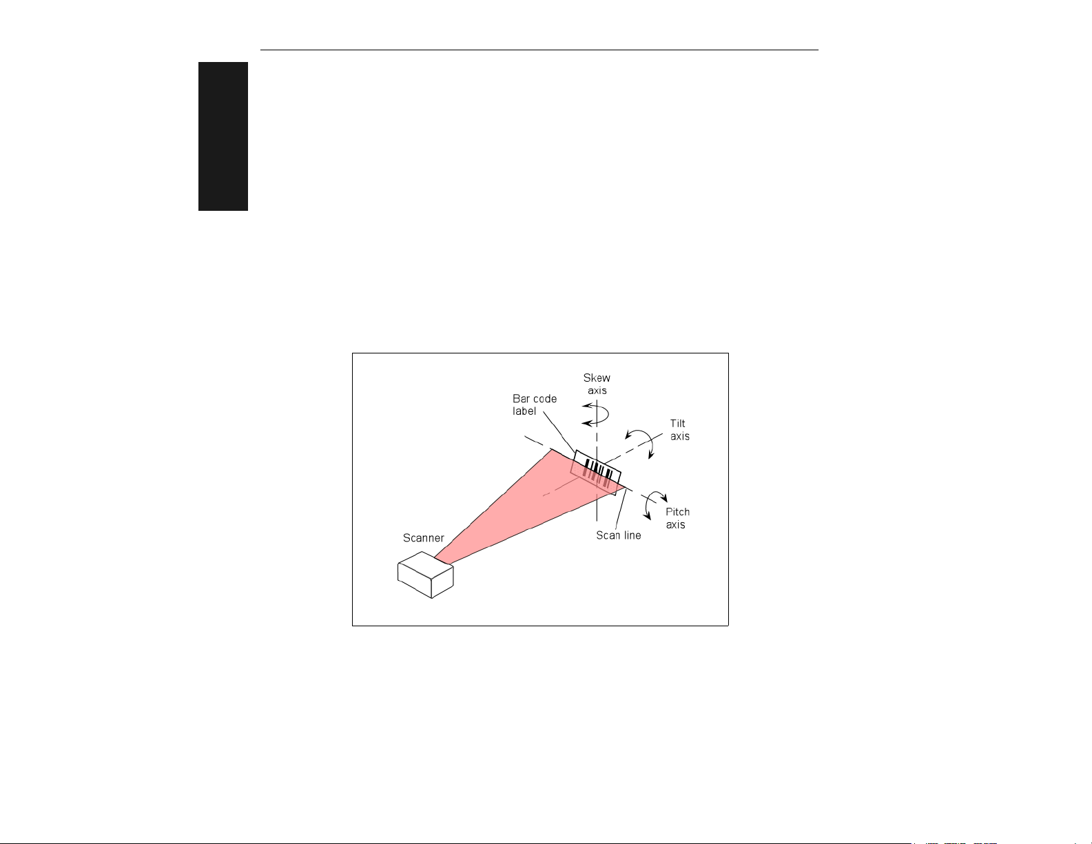
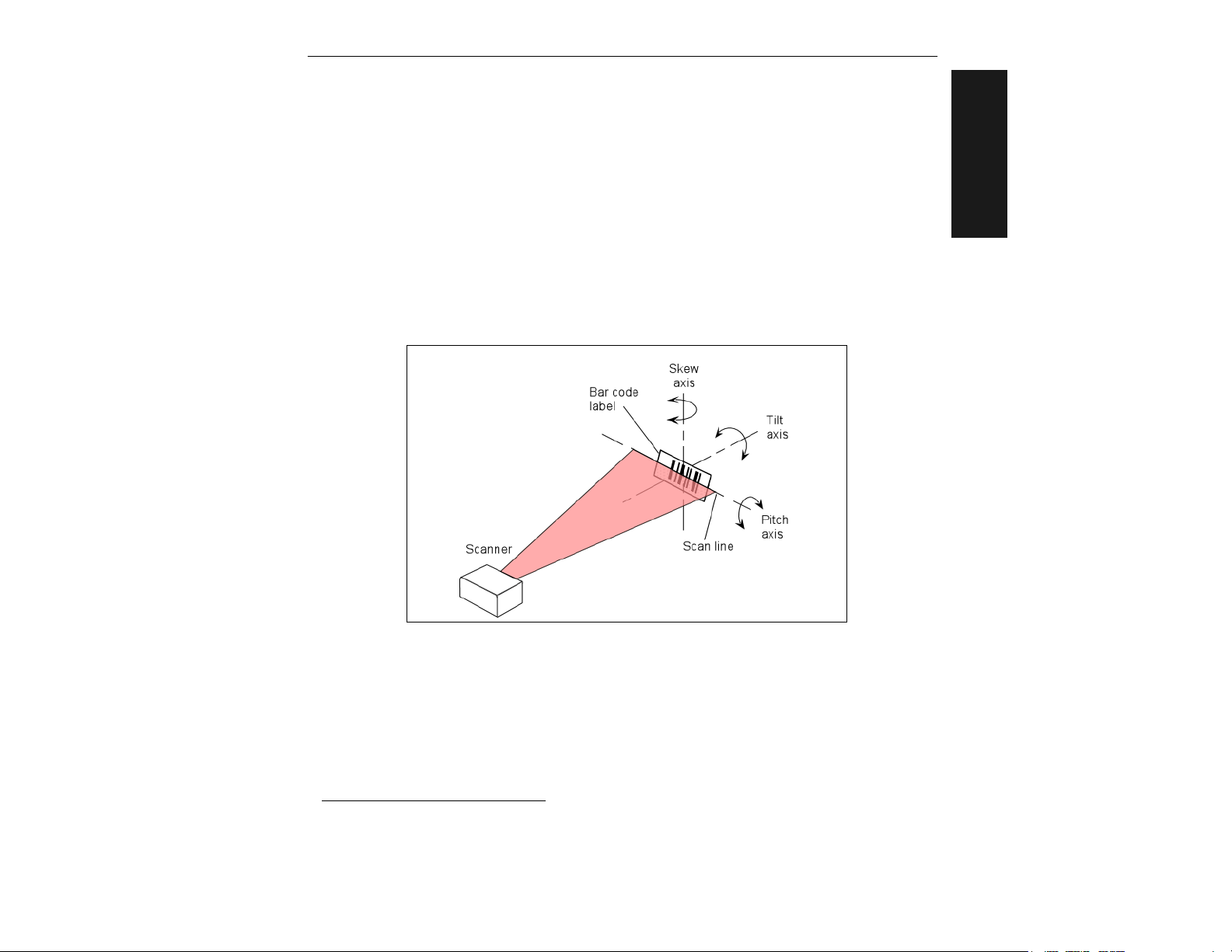
b) Avoid excessive tilt, skew, or pitch. Maximum tilt is determined by label charac-
teristics and the number of scans required. Maximum skew is ±40°; maximum
pitch is ±50°.
c) Pitch label slightly to avoid specular reflection, the return of direct, non-dif-
fused light. For the MS-810 raster scanner, specular reflection is avoided by
pitching labels at least 5° plus or minus from a line perpendicular to the mir-
2
ror.
1
1–Quick Start
Figure 1-5 Tilt, Skew, and Pitch Axes
Note: Another way to avoid specular reflection is to skew the scanner slightly in
relation to the label.
1. Maximum tilt is determined by label characteristics and number of scans required.
2. The specular reflection zone is a narrow zone straight out from the scanner in which direct
reflected light from a label can distort the scanner’s ability to distinguish bars from spaces.
MS-810 Industrial Scanner User’s Manual
1-5
Page 16
Chapter 1
Step 5 Mount Scanner
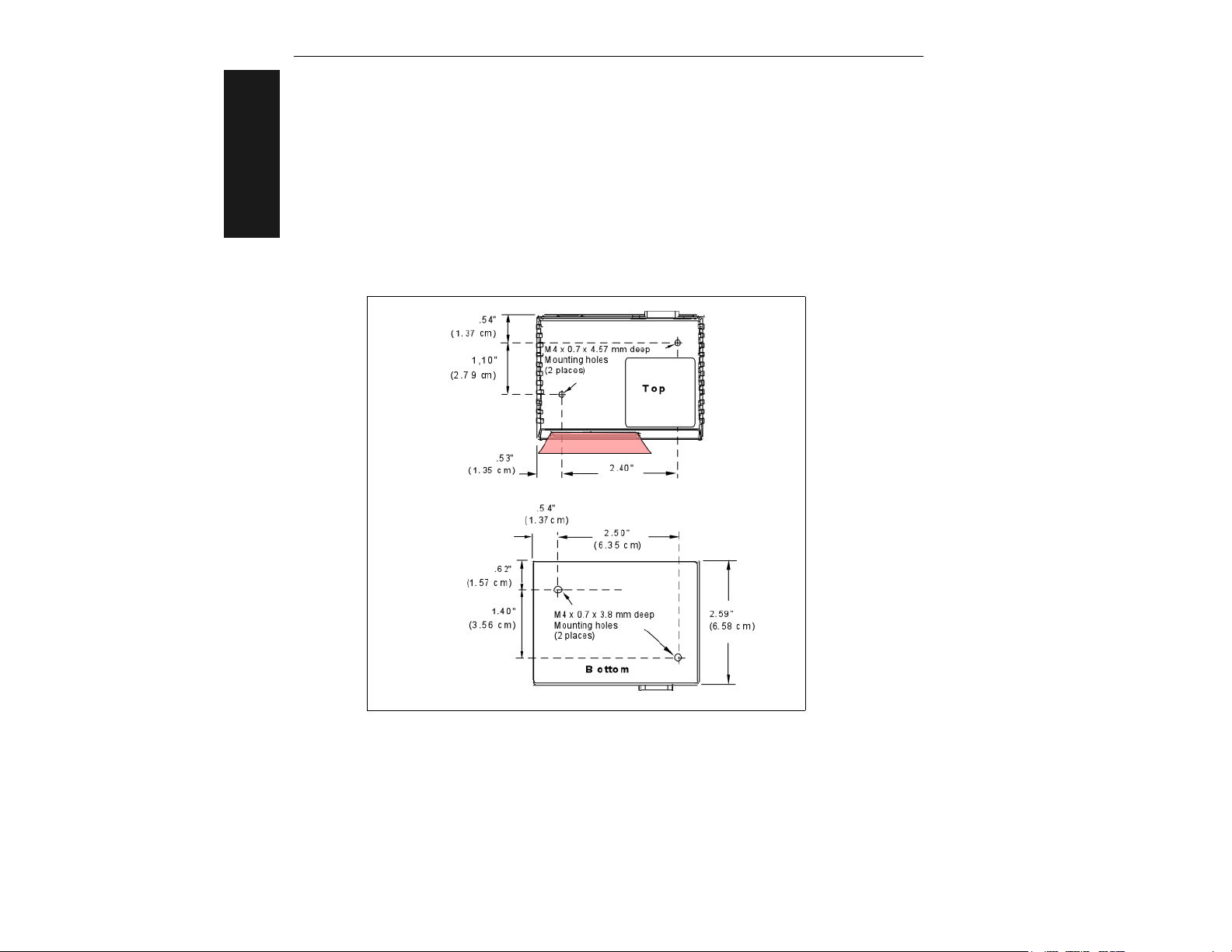
The MS-810 scanner can be top or bottom mounted depending on your model type.
1–Quick Start
Use the measurements provided in figure 1-6 to locate centers of mounting holes
and drill as specified:
Top mount – drill two 0.16 inch (4.06 mm) diameter holes.
Bottom mount – drill two 0.203 inch (5.16 mm) diameter holes.
Figure 1-6 MS-810 Mounting Dimensions
Caution: Maximum penetration depth of screws is 0.29 inch (7.37 mm) for top mount or
0.15 inch (3.81 mm) for bottom mount.
Caution: To prevent twisting or distortion of the scanner housing, ensure that the mount-
ing surface or bracket is flat.
1-6
MS-810 Industrial Scanner User’s Manual
Page 17
Step 6 Establish Communications
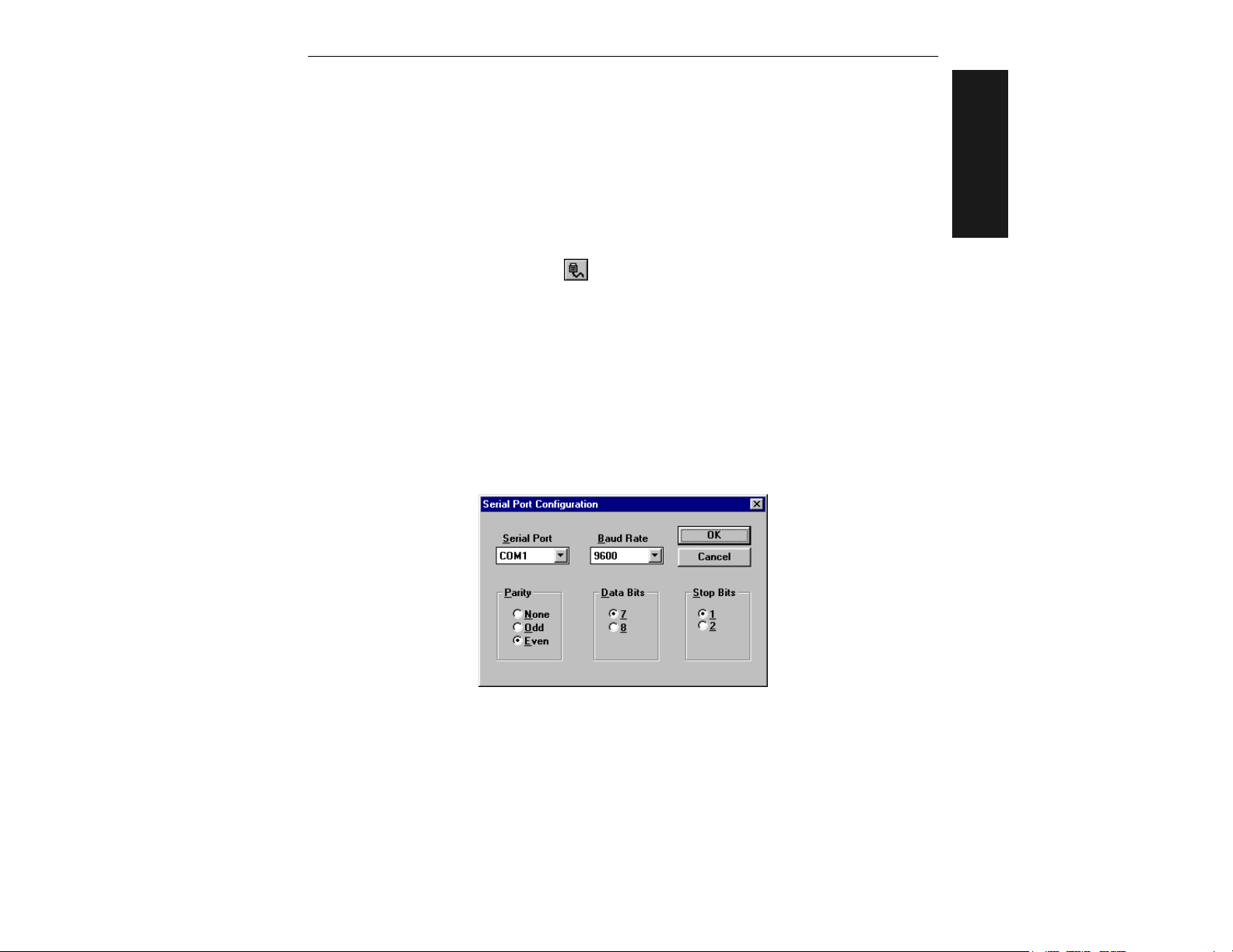
To set up the host communications, from the ESP™ main menu:
a) Select Serial Port and Configure from the pull-down menus.
b) Make the port selection from Serial Port options COM 1 through COM 8. (Usually
COM 2 for desktops and COM 1 for laptops.)
c) Click the Auto Baud button or select Auto Baud from Serial Port pull
down menu.
ESP will cycle through the various baud, etc. combinations until communications are
established (look for the CONNECTED banner on your screen) or the cycle is completed without connecting and a DISCONNECTED banner appears on your screen.
You can also interrupt the search by clicking the Stop button.
Allow some time for the auto baud routine to test most of the combinations. You can
watch this at the bottom of the dialog box. Once it has found it, it will change the
host’s settings to match the scanner’s.
baud, Even Parity, 7 Data
The default settings for the MS-810 scanner are 9600
Bits, and 1
Stop Bits.
1–Quick Start
MS-810 Industrial Scanner User’s Manual
1-7
Page 18
Chapter 1
Step 7 Configure Scanner
You can make changes from the default settings by modifying individual ESP menus
and saving those changes to the scanner.
1–Quick Start
For explanations of menu configuration settings, see Chapter 2, “ESP Menu Con-
figuration.”
Note: When you save communications changes to the scanner, serial port settings
are automatically matched.
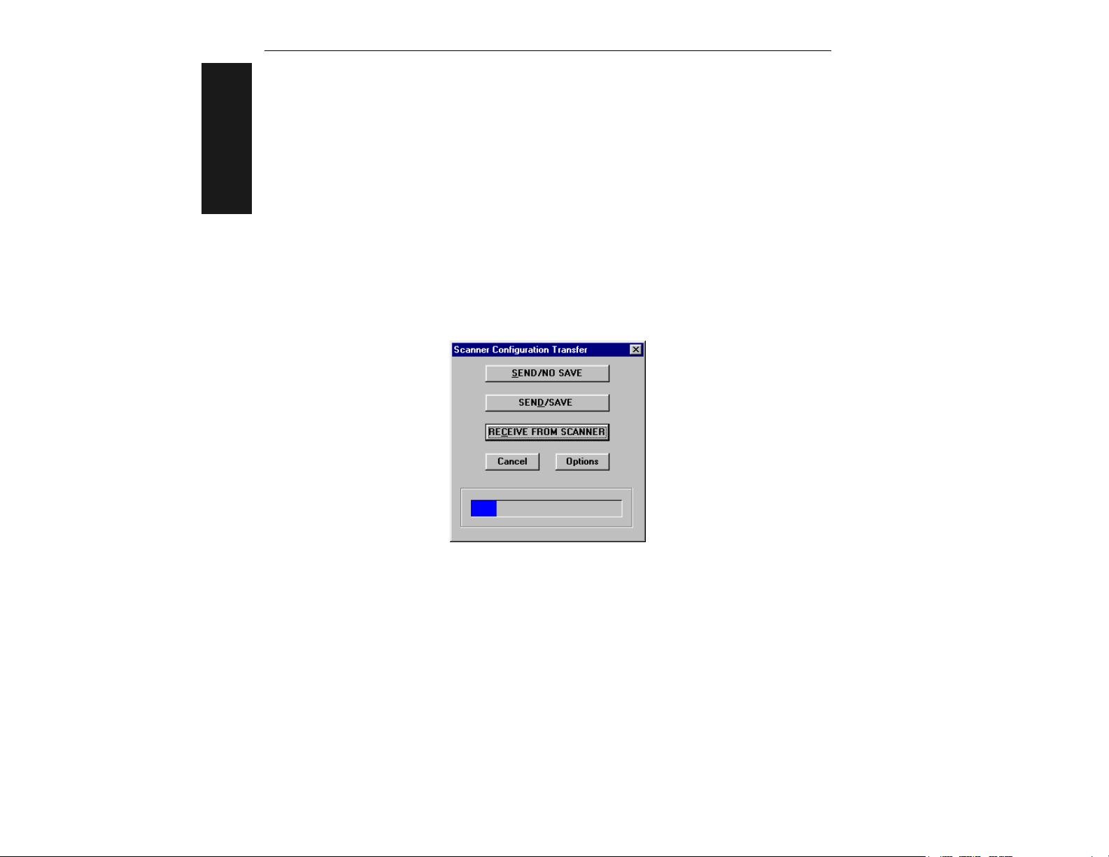
You can check the scanner’s settings at any time by clicking SEND/RECV and
Note:
RECEIVE FROM SCANNER to receive the scanner’s current settings into ESP.
As data is being received a blue bar will fill across the bottom of the dialog box.
1-8
MS-810 Industrial Scanner User’s Manual
Page 19
Step 8 Test Decode Rate with Static Label
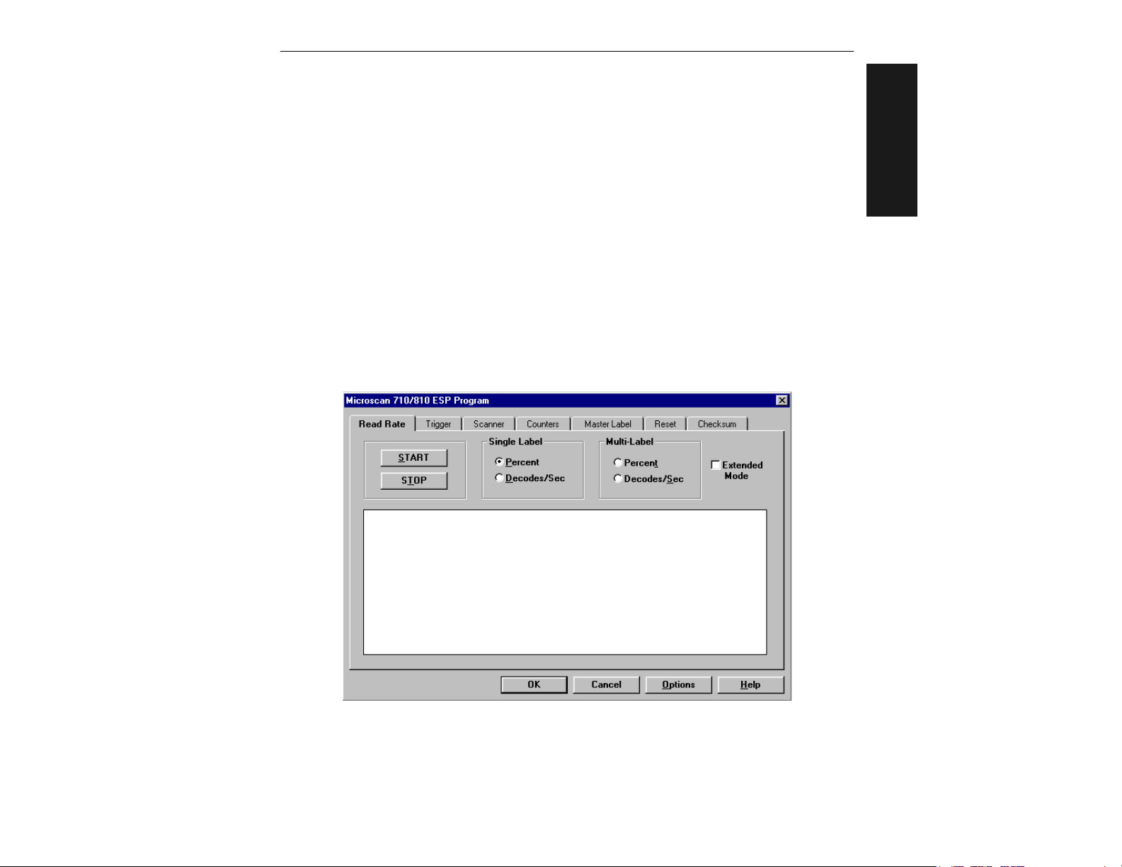
a) Position the label in front of a functioning scanner, click on the Utilities button,
and in the Read Rate dialog either click the Percent or Decodes/Sec radio but-
ton and click Start, or enter the <Cp> or <C> command from the host terminal
to launch test.
b) Observe rate. (The percent or decode rate is added to the front of the data
string.)
c) End the test by clicking the Stop button or the <J> command.
If, after making adjustments, you have changed the read range or another
:
Note
parameter used in the number of scans formula, you should recalculate the number
of scans (see “Number of Scans” on page A-18).
Note: Variations between labels are common. For this reason, the greater number
of sample labels you test, the more likely you are to achieve optimum decode rates.
1–Quick Start
MS-810 Industrial Scanner User’s Manual
1-9
Page 20

Chapter 1
Step 9 Test Decode Rate with Moving Label
Once you’ve mounted the scanner and established a good read rate with a stationary label, you can repeat the test with a moving label.
1–Quick Start
To ensure reliable scanning, you need to apply a minimum of five scans to each
label. This means that all variables, label speed, read range, etc. are significant.
To calculate in advance the number of scans that the label will receive, use the formulas described in Appendix G, “Number of Scans,” on page A-18.
1-10
MS-810 Industrial Scanner User’s Manual
Page 21

Step 10 Increase the Number of Scans
Where possible, you can increase the number of scans a label receives by:
• Increasing label height
• Decreasing label length
• Increasing scan rate (spinning mirror speed)
• Slowing label speed
See Appendix G, “Number of Scans,” on page A-18.
1–Quick Start
MS-810 Industrial Scanner User’s Manual
1-11
Page 22

Chapter 1
1–Quick Start
1-12
MS-810 Industrial Scanner User’s Manual
Page 23

Chapter
ESP Menu
2
Configuration
2–Menu Config.
Chapter Contents
About the Menu Configuration Program ..............................................2-2
Communications Menu ........................................................................2-5
Protocol Menu....................................................................................2-12
Operation Menu .................................................................................2-16
Code Type Menu ...............................................................................2-25
Output Menu .....................................................................................2-32
Setup Menu........................................................................................2-38
With Microscan’s ESP™ (Easy Setup Program) configuration changes can be made in
the ESP menus and sent and saved to your scanner. You can also send serial commands to the scanner via the ESP’s Terminal window.
ESP can receive configuration settings from a scanner and post these in the Current
Menu Settings window.
Multiple configuration settings can be saved to host computer and later recalled and
loaded into any MS-810 scanner.
MS-810 Industrial Scanner User’s Manual
2-1
Page 24
Chapter 2
About the Menu Configuration Program
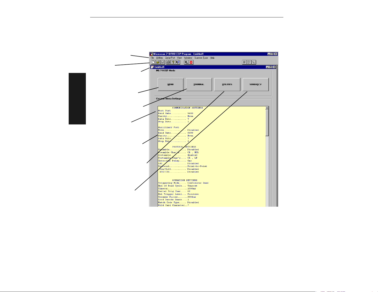
Pull down menus
Toolbar
An “Untitled...” file loads
with the original default
settings
Access configuration
menu changes here.
Emulation window displays
echoed commands and
data
2–Menu Config.
You can also access the
configuration menus by
clicking any item here.
Also titled
“Current Menu/Scanner
Settings” following a
save or upload
Allows you to perform tests
and access operational
information
Allows you to
download/upload between
the scanner and the host
Figure 2-1 Configuration Program - Main Menu
Using ESP to Configure the Scanner
This is the window you will see when you launch the Easy Setup Program.
To access the configuration menus, click on the MENU button.
If using a mouse, single click on menu items and enter text as appropriate. If using
the keyboard, use the Alt key plus underlined letters and the tab key to move to the
desired field, use arrow keys or the space bar to scroll through selections, and the
Enter key to accept changes.
2-2
MS-810 Industrial Scanner User’s Manual
Page 25

About the Menu Configuration Program
Saving Settings to the Scanner
You can access the SEND/RECV box by clicking it directly from the Current Settings
window, or from within any of the configuration menus, click Apply. To save changes
to the scanner, select Apply in the menu pages. (Clicking OK on these menu pages
will only update the items in the Current Settings window.) From within the SEND/
to initialize, send data, and reset counters only, or
RECV box, click SEND/NO SAVE
SEND/SAVE to initialize, reset counters, and save these settings to the scanner’s
nonvolatile memory.
Receiving Settings from the Scanner
To update Current Settings in ESP, click SEND/RECV and then RECEIVE FROM SCANNER.
Note: If receiving scan data and you are in Continuous Read, labels being scanned
may interfere with your data request.
Saving Settings to the Host Computer
When saving a file by selecting SAVE AS (or SAVE) from the File pull-down menu,
the settings are saved only on the computer’s hard drive or other storage medium.
This is particularly useful for saving special sets of settings that you may want to
recall later and use for a different application.
Creating a New Configuration File
To create a new file of configuration settings, first be sure you’ve saved the current
configuration file to the computer’s hard drive or other storage device. Next pull down
the File menu in the ESP and select New. A new Untitled window will open with a listing of the default settings. Change these settings to suit your requirements and save
this file to the computer’s hard drive under a new name. These settings can also be
downloaded to the scanner at any time under a name of your choice.
2–Menu Config.
Restoring Default Settings
Note: Be certain that you’ve saved any other configuration files to the host computer
that you may want to reload later.
To restore defaults for individual menus in ESP, click the DEFAULT button on the spe-
cific menu. To save those settings to the scanner, click Apply.
To restore defaults to the scanner (for ALL menus), click the DEFAULT button on the
Interface tab of the Utilities menu, or send an <Ad> serial command. You can also
default by hardware command.
MS-810 Industrial Scanner User’s Manual
2-3
Page 26

Chapter 2
Loss of Communications
Making changes to communications parameters such as Baud Rate, Parity, Stop Bits,
LRC, etc. without corresponding changes in linked device(s) can result in the loss of
menu access. If this should occur, try ESP Auto Baud command or restore defaults.
Caution: Defaulting the scanner will reset all standard configuration parameters
except Scanner Type, Scans per Second, and Gain Adjustment to their original default
values.
Note: Power must be available to the scanner during the default procedure.
2–Menu Config.
2-4
MS-810 Industrial Scanner User’s Manual
Page 27
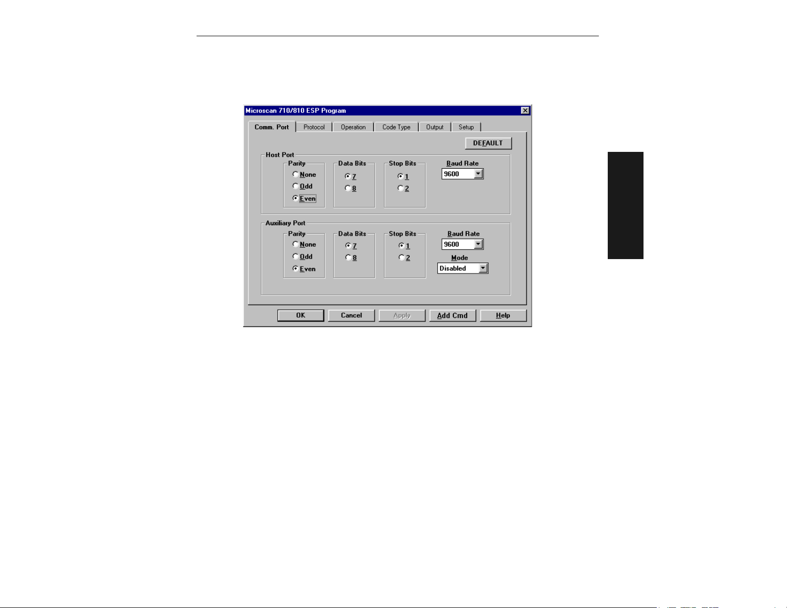
Communications Menu
Click the Menu button to access the menus.
Communications Menu
2–Menu Config.
Figure 2-2 Communications Menu Structure
Default
Clicking the DEFAULT button will reset all parameters on the current menu to
defaults. This does not take effect until it is saved to the scanner with the SEND/NO
SAVE or SEND/SAVE buttons.
Note: When you make and save menu communications changes to the scanner, those
changes will automatically be matched in the Serial Port pull-down options.
Host Port
Note: Changes in Communications parameters or assigning an address to the scanner can
cause loss of communications with the configuration terminal when you exit the menu program (whether or not changes are saved for power-on).
MS-810 Industrial Scanner User’s Manual
2-5
Page 28

Chapter 2
Parity
Default: Even
Options: Even, Odd, None
Allows you to select an error detection routine in which one data bit in each character
is set to 1 or 0 so that the total number of 1 bits in the data field is even or odd.
Stop Bits
Default: One
Options: One, Two
Allows you to select the last one or two bits in each character to indicate the end of
the character.
Data Bits
Default: Seven
2–Menu Config.
Options: Seven, Eight
Allows you to establish the total number of bits in each character.
Baud Rate
Default: 9600
Options: 300, 600, 1200, 2400, 4800, 9600, 19.2K, and 38.4K
Allows you to set the number of bits transmitted per second.
Aux Port Parameters
Options for Baud Rate, Parity, Stop Bits, and Data Bits are identical to the host port
parameters on page 2-5 and are changed in the same manner.
Mode
Default: Disabled
Options: Disabled, Transparent, Half Duplex, Full Duplex, and Daisy Chain
Note: Aux Port is only available through Microscan’s IB-105.
Allows you to set communications parameters between the scanner and an auxiliary
port. An auxiliary port can be used to configure the menus, send data to the host, and
display data transmissions originating from the host or scanner.
Note: Aux Port cannot be used in conjunction with RS-485 or RTS/CTS on the host
port.
Note: The Aux Port baud rate should never exceed Host Port baud rate or auxiliary
port data could be lost.
2-6
MS-810 Industrial Scanner User’s Manual
Page 29
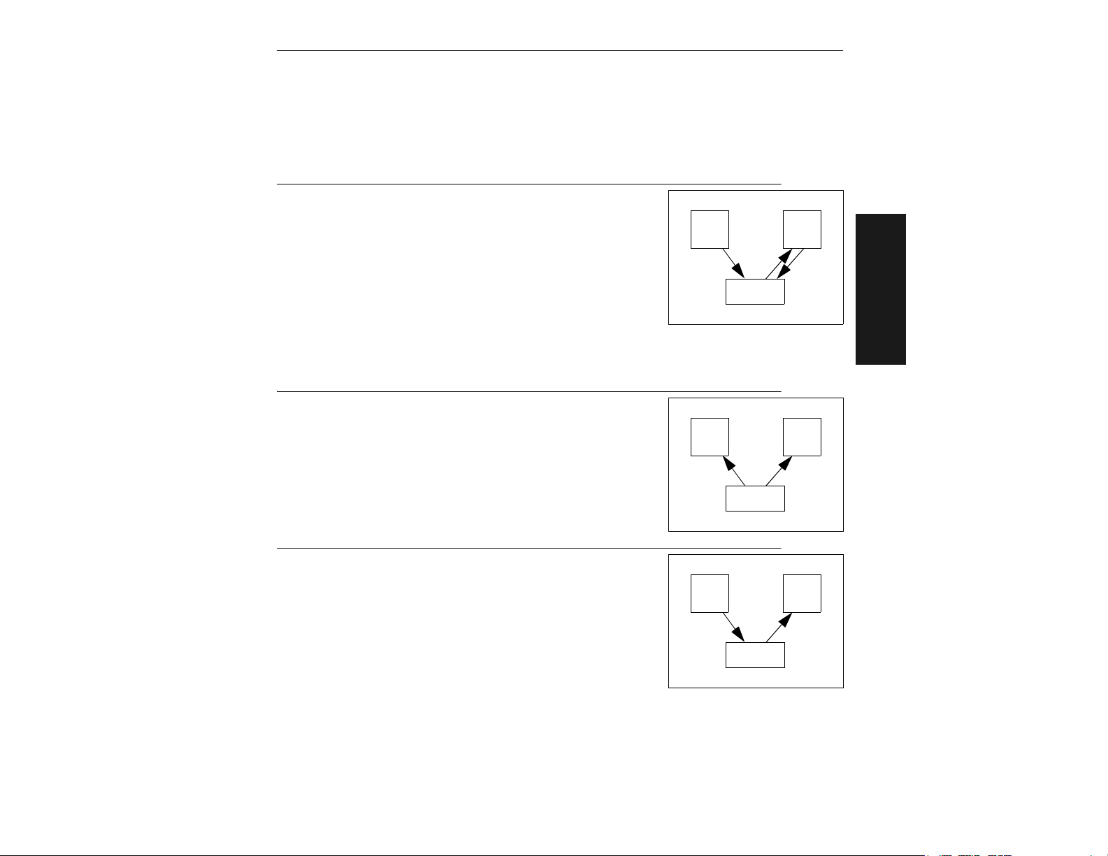
Communications Menu
Transparent
Used to batch data from the aux port to the host. The scanner buffers data from the
aux port and displays the keyed data on the aux port. The scanner transmits aux port
data to the host when a label is scanned or a carriage return is entered from the aux
port.
Data Initiated from the Aux Port
• Aux Port data is passed through to the host whenever a
return key is pressed at the aux port or whenever bar
Host
code data is sent. If sent with bar code data, it is processed on a first-in/first-out basis.
• Aux Port data to the host is always sent with a preamble
and a postamble.
MS-810
• If the scanner is in a polled mode to the host, aux port
data will still pass through.
•A <D> command is the only command accepted by the scanner from the aux port. All
other commands will pass through to the host.
Data initiated from the Scanner
• Transmission to the aux port occurs immediately upon a
good read.
Host
• Scan data to the aux port does not include a preamble or
a postamble.
• Communications with the aux port is always in Point-to-
MS-810
Point protocol, even if the host is in a polled protocol
mode.
Aux.
Port
Aux.
Port
2–Menu Config.
Data initiated from the Host
• In polled mode, data echoed from the host to the aux port
must be in the format
<B ____> (e.g., to send the word “LUNCH” to the aux
port, it must be sent in the format <BLUNCH>).
• In unpolled mode, all host data is echoed to the aux port.
MS-810 Industrial Scanner User’s Manual
Host
Aux.
Port
MS-810
2-7
Page 30
Chapter 2
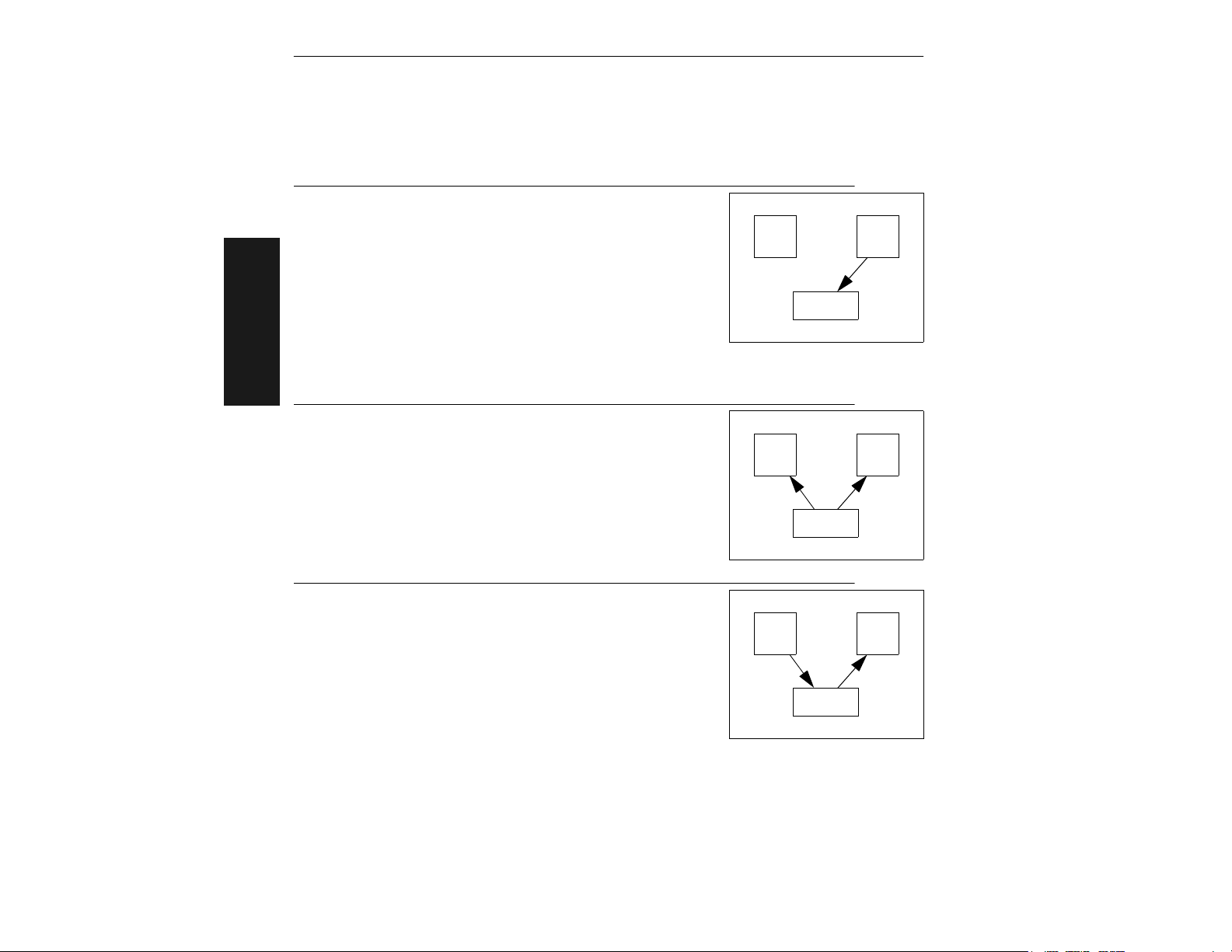
Half Duplex Mode
In half duplex mode all aux port data and bar code data is sent directly to the host.
Bar code data is displayed on the aux port screen at the same time the data is sent to
the host.
Data initiated from the Aux Port
• Aux Port data to the host is ignored if the scanner is in a
polled mode.
• Aux Port data or scanned data is sent to the host whenever it is received.
• Aux Port data is not echoed.
• Aux Port data to the host is always sent without a preamble or a postamble.
• <D> is the only command that is accepted by the scanner from the aux port. All other
2–Menu Config.
commands are passed through to the host.
Data initiated from the Scanner
• Scan data is transmitted to the aux port at the same time
it is transmitted to the host.
• Data transmission conforms with all parameters specified
in the configuration menu (e.g., Preamble, Postamble,
End of Read Cycle).
Host
MS-810
Host
MS-810
Aux.
Port
Aux.
Port
Data is initiated from the Host
• In polled mode, data echoed from the host to the aux port
must be in the format <B____> (i.e.: to send the word
“LUNCH” to the terminal, it must be sent in the format
<BLUNCH>).
• In unpolled mode, all host data is
echoed to the aux port.
2-8
MS-810 Industrial Scanner User’s Manual
Host
Aux.
Port
MS-810
Page 31
Communications Menu
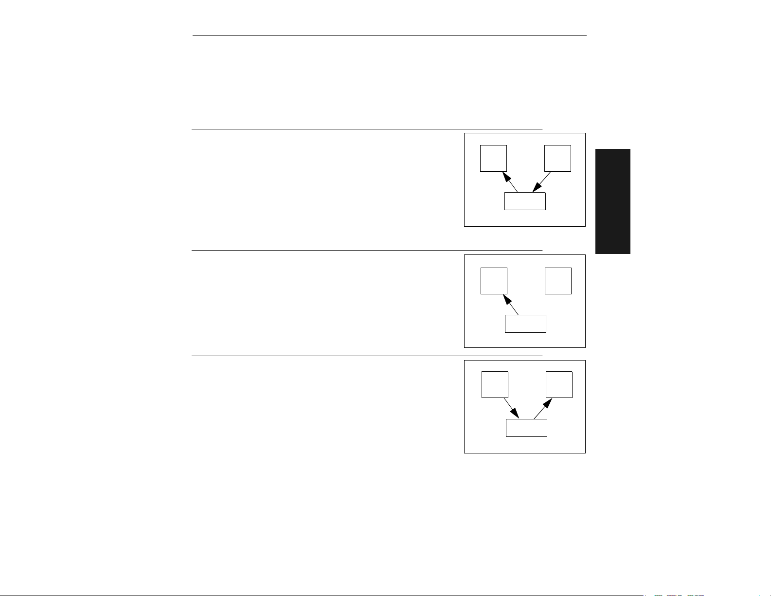
Full Duplex Mode
In full duplex mode, all aux port data and bar code data is sent directly to the host.
Bar code data is not displayed on the aux port screen.
Data initiated from the Aux Port
• Aux port data is passed directly through to the host whenever it is received by the scanner, unless the scanner is in
Host
a polled mode, in which case the data will be ignored.
• Aux Port data is not echoed.
• Aux Port data to the host will not have a preamble or a
MS-810
postamble.
•A <D> command is the only command accepted by the
scanner from the aux port. All other commands will pass through to the host.
Data initiated from the Scanner
• Scan data is not sent to the aux port.
Host
MS-810
Aux.
Port
Aux.
Port
2–Menu Config.
Data initiated from the Host
• In polled mode, data echoed from the host to the aux port
must be in the format <B____> (for example, to send the
word “LUNCH” to the terminal, it must be sent in the format <BLUNCH>).
• In unpolled mode, all host data is echoed to the aux port.
MS-810 Industrial Scanner User’s Manual
Host
Aux.
Port
MS-810
2-9
Page 32
Chapter 2
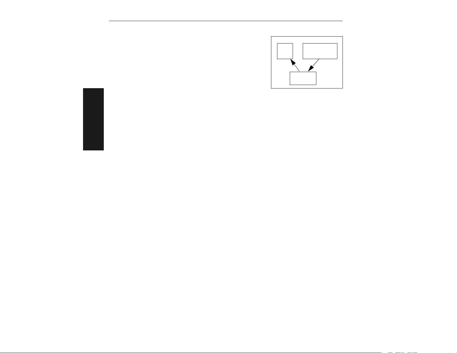
Daisy Chain Mode
In a daisy chain application, a primary scanner is linked
directly to the host and succeeding scanners are linked in
tandem. The source of transmitted data can be identified by
enabling and assigning daisy chain IDs to each scanner.
Just before sending a noread message, the primary scanner checks its auxiliary port for data. It waits a maximum
of 20 ms. If no character is received in 20 ms, it sends a
noread message to the host. If a complete message is received, it is sent to the host
instead of the noread message. If for example the primary scanner were set to timeout
in 100 ms, the first succeeding scanner could be set to 90 ms, the next to 80 ms, etc.,
thus assuring that a minimum of 20 ms elapses between transmissions.
Daisy-chained scanners can send a series of labels by enabling Multilabel and a common multilabel separator. If the primary scanner does not receive the expected number of labels, noread messages are appended to the data string to make up the
difference between the number of labels enabled in Multilabel (Number of Labels) and
2–Menu Config.
the number of labels read.
For example, a primary and two succeeding scanners have Number of Labels set to 3
and Multilabel Separator defined as %. If the primary and the first succeeding scanner
do not find labels, but the next succeeding scanner registers a good read, the transmitted results would be: label data % noread % noread.
The conditions for a daisy chain application are as follows:
1. The primary scanner’s trigger can be serial or external; the succeeding scanners
are automatically serially triggered.
2. All scanners are enabled to daisy chain mode.
3. Each scanner’s Aux port must have its Send and Receive connected to the Host port
of its succeeding scanner.
4. Each succeeding scanner in the daisy chain must be set to send its data no less
than 20 ms before its preceding scanner.
5. All but the primary scanner must have Postamble set to CR (^M) and enabled.
6. All but the primary scanner must have their noread messages disabled.
7. If Multilabel is enabled, Multilabel Separator characters and Number of Labels must
match in all scanners in the daisy chain.
8. Symbology ID enable/disable must be the same in all scanners.
9. All but the primary scanner must have their diagnostic warning messages disabled.
Host
Primary
Scanner
Succeeding
Scanner(s)
2-10
MS-810 Industrial Scanner User’s Manual
Page 33
Communications Menu
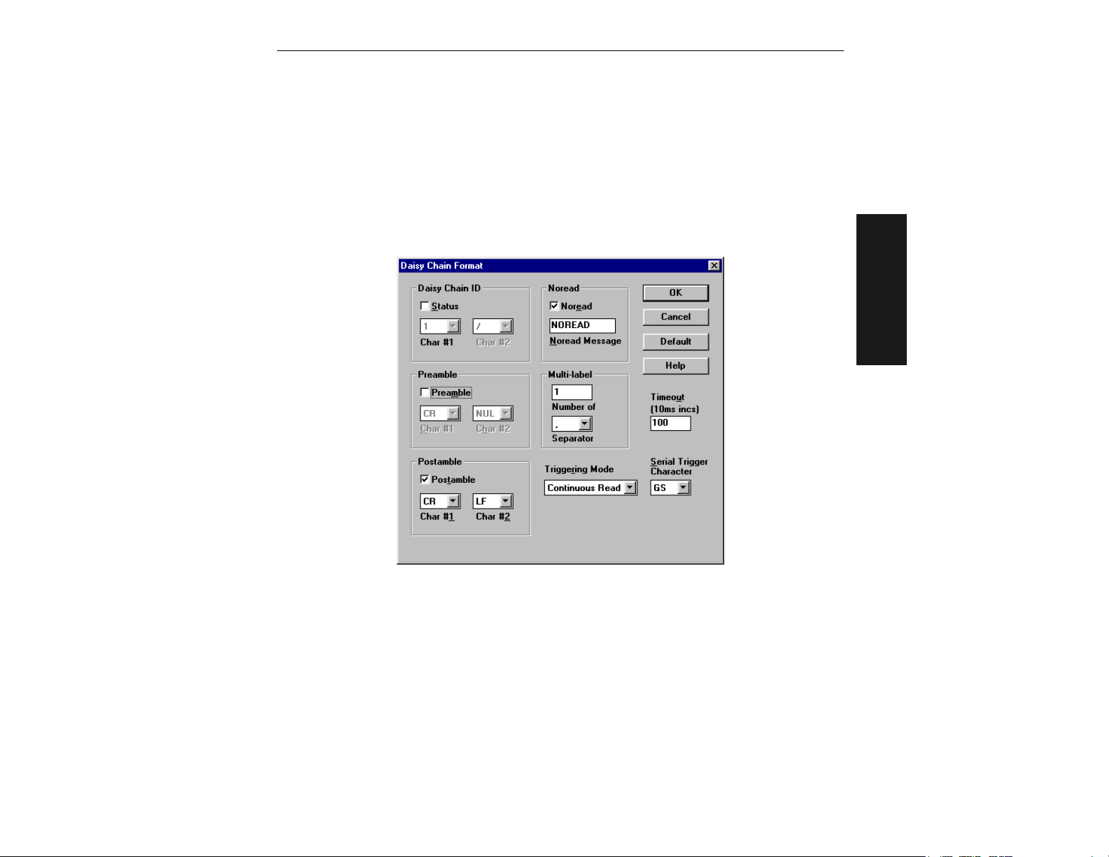
Daisy Chain ID Status
Default: Disabled
Options: Disabled, Enabled.
Daisy Chain ID
Default: 1/
Options: Any one or two ASCII characters.
Each scanner enabled for Daisy Chain can be assigned a one or two character Daisy
Chain ID that appears in front of the data decoded by that scanner. Enable/disable
and length must be the same in all scanners.
2–Menu Config.
MS-810 Industrial Scanner User’s Manual
2-11
Page 34
Chapter 2
Protocol Menu
Protocols define the sequence and format in which information is transferred between devices.
2–Menu Config.
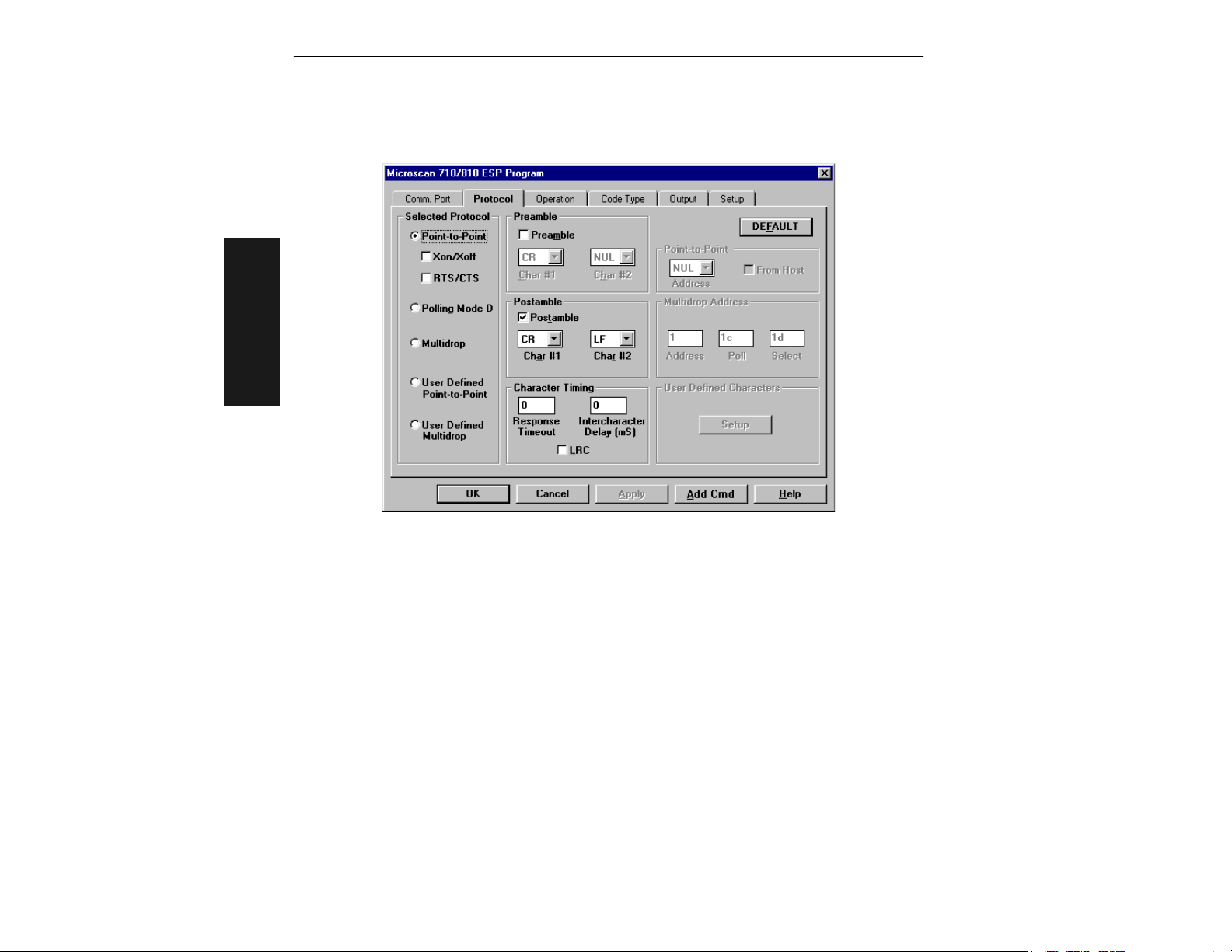
Figure 2-3 Protocol
Default
Clicking the DEFAULT button will reset all parameters on the current menu to
defaults. This does not take effect until it is saved to the scanner with the SEND/NO
SAVE or SEND/SAVE buttons.
Selected Protocol
Default: Point-to-Point
Options: Point-to-Point, Point-to-Point with XON/XOFF, Point-to-Point with RTS/CTS,
Point-to-Point with RTS/CTS & XON/XOFF, Polling Mode D, Multidrop, User
Defined, User Defined Multidrop Protocol
Point-to-Point
Has no address and sends data to the host (RS-232) whenever it is available and
without any request or handshake from the host.
Point-to-Point with RTS/CTS (Request-to-Send/Clear-to-Send)
Used only with RS-232. This is a simple handshaking protocol that allows a device to
initiate data transfers to the host with an RTS (request-to-send) transmission. The
2-12
MS-810 Industrial Scanner User’s Manual
Page 35

Protocol Menu
host, when ready, responds with a CTS (clear-to-send) and the data is transmitted.
CTS and RTS signals are transmitted over two dedicated wires (pins 6 and 10) as
defined in the RS-232 standard.
Point-to-Point with XON/XOFF (Transmitter On/Off)
Used only with RS-232. This selection enables the host to send a single byte transmission command of start (XON) or stop (XOFF). If an XOFF has been received from the
host, data will not be sent to the host until the host sends an XON. During the XOFF
phase, the host is free to carry on other chores and accept data from other devices.
Point-to-Point with RTS/CTS & XON/XOFF
Used only with RS-232. It is a combination of Point-to-Point with RTS/CTS and Pointto-Point with XON/XOFF.
Polling Mode D
Like Point-to-Point, Polling Mode D requires a separate connection to the host; but
unlike Point-to-Point, it requires an address and must wait for a poll from the host
before sending data. When in Polling Mode D, an address of 1 is automatically displayed on the configuration screen. However, during transmission, a 1C hex poll
address (FS) and a 1D hex select address (GS) are substituted for the 1.
Multidrop
Note: Scanners intended to link up to a Microscan MS-5000 multidrop concentrator
must be configured in standard Multidrop protocol.
Similar to Polling Mode D except that a unique poll address and select address are
required for each multidrop device, and only one host port connection is needed for up to
50 devices. (For Multidrop poll and select characters, see Table A-12, “Multidrop
Address Characters,” on page A-35.)
Requires a concentrator or controller using RS-485 communications. When Multidrop
is selected, the protocol characters for RES, REQ, etc. are assigned automatically.
(See “Appendix M — Multidrop Communications” on page A-33 for poll and
select sequences.)
2–Menu Config.
User Defined Point-to-Point
Note: A specific ASCII character must not be assigned more than once.
Used only with RS-232. User Defined is necessary when a new protocol must be
defined to match a specific host protocol. ASCII characters can be assigned as an
address and as protocol commands (RES, REQ, EOT, STX, ETX, ACK, NAK, From Host).
In order to enable a handshaking protocol, you must manually assign values where
necessary. When User Defined is selected, the displayed protocol commands match
those of the previously selected protocol. User Defined is considered to be in a polled
mode only if an address has been assigned. The address can be any ASCII character
from the ASCII table in Appendix D. If null is selected as the address, the scanner
will not function in a polling sequence. From Host, if enabled, allows the handshaking
protocol to be initiated from the host, if unpolled.
MS-810 Industrial Scanner User’s Manual
2-13
Page 36

Chapter 2
From Host
Default: Disabled
Options: Disabled, Enabled
Messages sent to the host from the MS-810 will always include the scanner’s defined
protocol. The status of From Host determines if messages sent to the MS-810 from
the host must also include the defined protocol. If From Host is disabled, the defined
protocol is not included. If From Host is enabled, the defined protocol must be
included. (See “Explanation of the From Host option,” on page 3-7 for further
information.)
Multidrop Addresses
No two scanners in the Multidrop Network can have the same address.
Each scanner in the network must have an address (from 01 to 50) assigned in its
configuration program.
Each address has its own separate poll and select address (from 1C to 7F hex).
2–Menu Config.
For example, during a polling sequence, Scanner 03 expects a 20 hex (“SP” ASCII poll
character) from the concentrator. And during a select command, it looks for a select
value 21 hex (“!” ASCII select character).
User Defined Multidrop
Used when connecting to a concentrator or other device that does not match standard Multidrop protocol.
Any single character (02 hex to 7E hex) in the ASCII table can be assigned as the address
character. The character chosen is used as the poll character and the subsequent ASCII
character becomes the select character. For example, if a ^B(02 hex) is selected as the
address, ^C (03 hex) becomes the select address that the host will use in sending host
select commands. (See Table A-12, “Multidrop Address Characters,” on page A-35.)
Note: Definitions of commands in User Defined and User Defined Multidrop must be
duplicated in host applications to enable poll and select sequences to execute correctly during transmission.
Note: Typically, parameters in User Defined Multidrop are defined by first enabling
Multidrop, then enabling User Defined Multidrop. This pre-loads Multidrop characters
into the parameters. You then change individual characters to match the host or other
requirements.
Preamble
Default: ^M (and a null). Corresponds to <CR><NUL> (carriage return/null) displayed
in the menu.
Options: Any ASCII character, including control characters.
Allows you to define a one or two character data string that can be added to the front
of the decoded data.
2-14
MS-810 Industrial Scanner User’s Manual
Page 37

Protocol Menu
Preamble (enable/disable)
Default: Disabled
Options: Disabled, Enabled (within any protocol)
Allows you to enable or disable the preamble character(s).
Postamble
Default: ^M^J
Options: Any ASCII character, including control characters.
Allows you to define a one or two character data string that can be added after the
decoded message. For example, defining the Postamble as a carriage return and line
feed would result in the display of each decoded message on its own line.
Postamble (enable/disable)
Default: Enabled
Options: Enabled, Disabled (within any protocol)
Allows you to enable or disable the Postamble character(s).
LRC (Longitudinal Redundancy Check)
Default: Disabled
Options: Disabled, Enabled
An error-checking routine that verifies the accuracy of transmissions. It is the exclusive OR of all characters following the SOM (start of message) up to and including the
EOM (end of message). What this means is that the binary representation of all the
characters in a transmissions are cumulatively added in a column and each resulting
odd integer is assigned a 1 and each even integer a 0 (two 1s = 0, two 0s = 0, a 1
and a 0 = 1). This extra LRC character is then appended to the transmission and the
receiver (usually the host) performs the same addition and compares the results.
2–Menu Config.
Response Timeout
Default: 12 ms
Options: 0 to 65,000 ms. A zero (0) setting causes an indefinite wait.
Allows you to set the time the scanner will wait before timing out if ACK, NAK, and
ETX are enabled, and a host response is expected.
Intercharacter Delay
Default: 0. Corresponds to 0 ms displayed in the menu.
Options: 0 to 255. Zero (0) causes no delay between characters.
Allows you to set the time interval in milliseconds between individual characters transmitted from the scanner to the host. A high setting will significantly slow down communications. For example, a 200 setting will result in a 1/5 second delay between each
character that is transmitted.
MS-810 Industrial Scanner User’s Manual
2-15
Page 38
Chapter 2
Operation Menu
2–Menu Config.
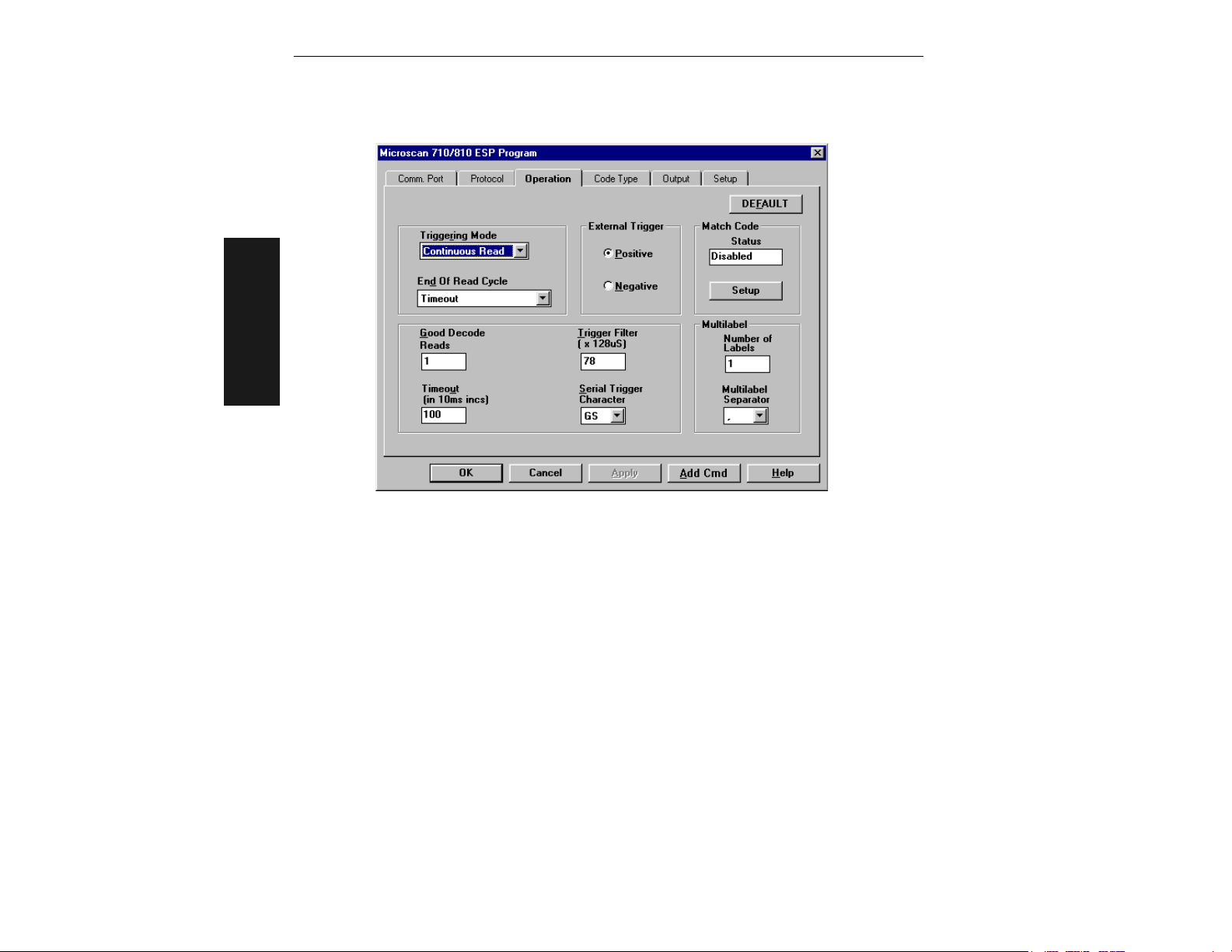
Figure 2-4 Operation Menu Structure
Default
Clicking the DEFAULT button will reset all parameters on the current menu to
defaults. This does not take effect until it is saved to the scanner with the SEND/NO
SAVE or SEND/SAVE buttons.
Tri gg e r in g M o de
Default: Continuous Read
Options: Continuous Read, Continuous Read 1 Output, External Level, External Edge,
Serial Data, Serial Data & External Edge
Allows you to establish the type of trigger event that will initiate or end the read cycle.
(See “End of Read Cycle” on page 2-18.)
Continuous Read
Note: If both Continuous Read and Match Code are enabled the scanner defaults to
Continuous Read 1 Output mode.
Trigger input options are disabled and the scanner is always in the read cycle. Bar
code data is decoded, and label information is transmitted repeatedly, as long as the
2-16
MS-810 Industrial Scanner User’s Manual
Page 39
Operation Menu
label is in the read range of the scanner. When To Output options have no affect on
Continuous Read. Continuous Read is useful in testing label or scanner functions.
Continuous Read 1 Output
Note: Enabling Continuous Read 1 Output when Number of Labels (page 2-21) is set
to any number greater than one will cause Number of Labels to default back to one.
Label data is immediately transmitted once every time new label data is placed in
front of the scanner. With Timeout enabled for End Of Read Cycle, if the label doesn't
change, the scanner will repeat the output at the end of each subsequent timeout
period. For example, if Timeout were set to one second, the scanner would output the
label data immediately, and then repeat the output at intervals of one second, for as
long as the label continued to be scanned.
With Timeout disabled (that is, End Of Read Cycle set to New Trigger), the scanner
will output the current label data immediately, but output it only once. A new label
appearing at any time in the scan range will produce a new read output as long as the
new label is not identical to the previous label.
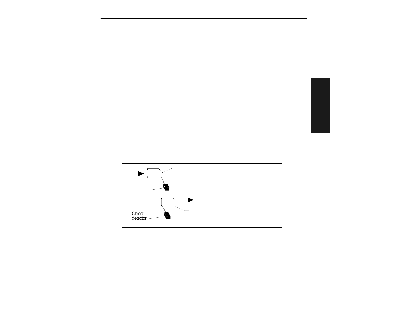
External Level
Allows a read cycle to be initiated by a trigger signal from an object detector when an
object appears within the detector’s range. The read cycle exists as long as the detector “sees” the object and does not end until the object moves out of the detector’s
range even if a good read or timeout occur sooner (figure 2-5).
1
Object
detector
Firs t trigger
1
An object, moving in front of the detector beam,
causes the first trigger (r ising edge trigger) signal to
be sent to the scanner, initiating the read cycle.
2–Menu Config.
1
Object
detector
Second trigger
The same object, moving out of t he detect or's beam,
causes a se cond trigger (falling edge tr igger) signal to
be sent to the scanner, e nding t he read cycle.
Figure 2-5 External Level Trigger Signals
1. Level and Edge apply to the active logic state (positive or negative) that exists while the object
is in a read cycle, between the rising edge and falling edge. Rising edge is the trigger signal
associated with the appearance of an object. Falling edge is the trigger signal associated with
the subsequent disappearance of the object.
MS-810 Industrial Scanner User’s Manual
2-17
Page 40
Chapter 2
y
External Edge
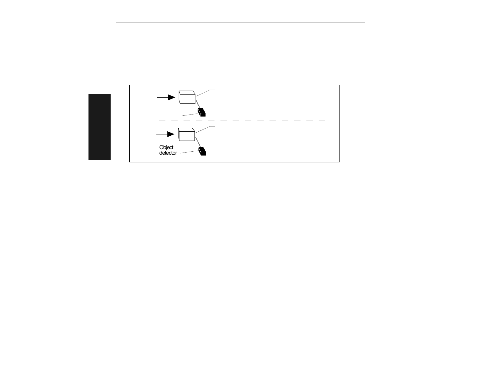
As with Level, Edge allows a read cycle to be initiated by a trigger signal from an
object detector when it detects the appearance of an object (rising edge). But unlike
Level mode, the removal of an object (falling edge) does not end the read cycle. With
Edge enabled, the read cycle ends with a good read output, a timeout, or a new trigger (figure 2-6 on page 2-18).
First rising edge trigger
1
Object # 1, moving in fro nt of the detector beam, caus es
the firs t trigger (r ising edge trigger) signal to be sent to the
scanner, initiating the read cycle.
Object
detector
Subsequent ris ing edge trigger
2
2–Menu Config.
Object
detector
Object # 2, moving in front of the detector's beam, causes
a second trigger (rising edge trigger ) signal to be sent to
the sc anner. This sig nal initiat es a new read cycle
ends the previous read cycle
Timeout and New Trigger is enabled and a good read or
timeout has not alread
provided
occur red.
that New Trigger or
and
Figure 2-6 External Edge Trigger Signals
Serial Data
The scanner accepts an ASCII character from the host or controlling device as a trigger to start a read cycle. Serial data trigger behaves the same as External Edge.
Serial Data & External Edge
The scanner accepts either an external trigger or a serial ASCII command to start a
read cycle.
End of Read Cycle
Default: Timeout
Options: Timeout, New Trigger, Timeout & New Trigger
Allows you to choose the circumstances that will end the read cycle. The read cycle is
the time during which the scanner will receive and process label data. When the Triggering Mode option is set in an External or Serial mode of operation, the trigger event
initiates the read cycle.
Note: When operating in Continuous Read or Continuous Read 1 Output, the scanner
is always in the read cycle.
2-18
MS-810 Industrial Scanner User’s Manual
Page 41

Operation Menu
Timeout
Can end the read cycle after a specified period of time, and if no label has been read,
causes a noread message, if enabled, to be transmitted.
With either External Edge, Serial Data, or Serial Data & Edge enabled, a timeout ends the
read cycle.
With External Level enabled, the read cycle does not end until the falling edge trigger
occurs, and the next read cycle does not begin until the next rising edge trigger.
With Continuous Read 1 Output enabled, a timeout initiates a new read cycle and
allows the same label to be read again.
New Trigger
Ends the read cycle at the occurrence of a new trigger event, and if no label has been
read, causes a noread message, if enabled, to be transmitted at the occurrence of the
new trigger event.
With either External Edge, Serial Data, or Serial Data & Edge enabled, and edge or
serial trigger ends a read cycle and initiates the next read cycle. With External Level
enabled, a falling edge trigger ends a read cycle, However, the next read cycle does
not begin until the occurrence of the next rising edge trigger.
Timeout & New Trigger
Ends the read cycle after a specified period of time or at the occurrence of a new trigger event, and if no label has been read, causes a noread message, if enabled, to be
transmitted.
With either External Edge, Serial Data, or Serial Data & Edge enabled, a timeout, or
an edge or serial trigger, whichever comes first, ends the read cycle.
With External Level enabled, the read cycle does not end until the occurrence of a falling edge, and the next read cycle does not begin until the next rising edge trigger.
2–Menu Config.
Timeout (in 10 ms incs)
Default: 100 (one second). Corresponds to 1000 ms displayed in the menu.
Options: 0 to 65535. Divide the number to be entered by 100 for time in seconds.
Note: Timeout or Timeout & New Trigger under End of Read Cycle (page 2-19) must
be enabled for Timeout (in 10 ms incs) to take effect.
Allows you to define the duration of the timeout period.
MS-810 Industrial Scanner User’s Manual
2-19
Page 42

Chapter 2
Serial Trigger Character
Default: ^]. Corresponds to <GS> displayed in the menu.
Options: Any single ASCII character, including control characters, except NUL (00H),
an existing host command character,1 or an on-line protocol character.
Note: Serial Data (page 2-18) or Serial Data & Edge (page 2-18) must be enabled
for Serial Trigger Character to take effect. “N/A” is displayed in the menu when all
other triggering modes are enabled.
Allows you to define a single ASCII character as the host serial trigger character that
initiates the read cycle. The serial trigger is considered an on-line host command and
requires the same command format as all host commands (that is, to be entered
within the < > brackets).
External Trigger Polarity
Default: Positive
Options: Positive, Negative
2–Menu Config.
Note: External Level (page 2-17), External Edge (page 2-18), or Serial Data &
Edge (page 2-18) must be enabled for External Trigger Level to take effect. “N/A” is
displayed in the menu when all other triggering modes are enabled.
Allows you to determine whether a positive or negative transition will initiate the read
cycle.
Note: If using the Microscan object detector (P/N 99-440001-03), use positive trigger
polarity.
Tri gg e r F i l t e r L ev el
Default: 78 (approximately 10 ms). Corresponds to 9984 µs displayed in the menu.
Options: 2 to 255 (approximately 0.256 ms to 32 ms in 0.128 ms increments). Multi-
ply the number to be entered by 128 for time in microseconds, then divide
by 1000 for time in milliseconds.
Allows you to set a trigger bounce filter duration.
1. For example, assigning an upper case D would nullify the <D> (Enter Menu Configuration)
command. For a list of operational commands used by the scanner, see Chapter 4, “Operational
Commands.”
2-20
MS-810 Industrial Scanner User’s Manual
Page 43

Operation Menu
Good Decode Reads
Default: 1
Options: 1 to 31
Allows you to select the number of good reads (from 1 to 31) required per label
before a good decode output.
Note: Be sure to set the value within the determined scan rate for the scanning setup
so that the scanner is capable of scanning a label the required number of times.
New Master Pin
Default: Disabled
Options: Disabled, Enabled
Note: Match Code Type (page 2-22) and a triggered mode (page 2-16) must be set for
Enabled or Sequential for New Master Pin to take effect.
Allows you to momentarily connect pin 12 to ground in order to clear any existing
master label information from memory and allows the next label to be read as the
new master label information.
Number of Labels
Default: 1
Options: 1 to 6
Note: If Number of Labels is set to any number greater than one while Match Code
Type or Continuous Read 1 Output is enabled, Number of Labels will default back to
one.
Note: If using Supplementals option for UPC, see “Supplementals,” on page 2-29
for specific directions on defining Number of Labels.
Allows you to choose the number of different labels that can be read in a single trigger
event. The following conditions apply:
1. Each label must be different to be read.
2. The maximum number of characters in any one label is 64.
3. The maximum number of characters in a single scan line is 384.
4. The maximum number of characters for all labels is 384, including preamble, postamble, and all spaces and commas.
5. All noread messages are posted at the end of the data string.
6. If more than one label is within the scan beam at the same time, label data may not
be displayed in the order of appearance.
2–Menu Config.
MS-810 Industrial Scanner User’s Manual
2-21
Page 44
Chapter 2
Multilabel Separator
Default: , (comma)
Options: Any available ASCII character, except NUL.
Allows you to choose the separator character to be inserted between each label.
Note: UPC separator character, if used, must be different than the multilabel separator.
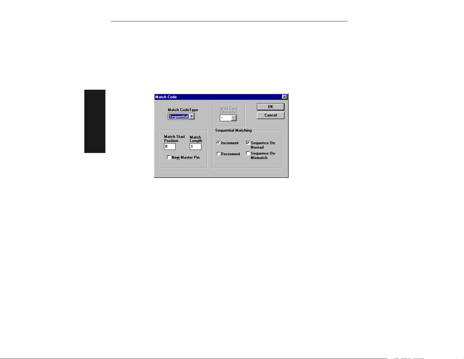
Match Code Type
2–Menu Config.
Figure 2-7 Match Code Type
Default: Disabled
Options: Disabled, Enabled, Wild Card, and Sequential
When not disabled, allows you to enter a master label into the scanner's RAM to be compared with subsequently scanned labels. The results of this comparison determine the
scanner’s data and relay outputs, if enabled.
The following conditions apply:
1. A triggered mode (page 2-16 to page 2-18) must be enabled for Match Code Type
to take effect.
2. Not disabling Match Code Type when Number of Labels is set to any number greater
than one will cause Number of Labels to default back to one.
3. If you wish to send a pulse on a Good Read, Match Code Type must be disabled (see
“Output On” on page 2-34).
Disabled
Disabled has no effect on operations.
Enabled
Instructs the scanner to compare labels or portions of labels with the master label.
2-22
MS-810 Industrial Scanner User’s Manual
Page 45

Operation Menu
Sequential
Instructs the scanner to compare labels or portions of labels for sequential numbers in
ascending or descending order.
There are four ways to load a master (see “Master Label Entry” on page 2-24). In
every case sequencing occurs after each match. See “Match Code Type” on page
3-11 for special noread and mismatch sequences.
Wild Card
Allows you to enter user defined wild card characters in the master label.
For example, with wild card defined as the default asterisk, entering URGENT** as your
master label will result in matches for URGENT, URGENT1, and URGENT12 but not for
URGENT123.
As in the above example, when wild cards are appended to the end of the master
label, labels of variable lengths can result in matches. However, wild cards in the
beginning or center of a label (e.g., UR**NT) do not allow for variable label lengths.
Matchcode Master
Default: (blank)
Options: Displays current master and accepts user entry up to 64 characters.
Allows you to edit an existing master or type in a new master label from your keyboard.
Sequential Matching
Default: Increment
Options: Increment, Decrement
Defines the order (ascending or descending) in which labels will be compared when
Match Code Type is set to Sequential.
2–Menu Config.
Match Start Position
Default: 0
Options: 0 to 64
Match Start Position must be set to 1 or greater to enable this feature.
Defines the first character in the label (from left to right) that will be compared with
those of the master label when Match Code Type is set to Enabled or Sequential. For
example, if you set Match Start Position to 3, the first 2 characters read in the label
will be ignored and only the 3rd and subsequent characters to the right will be compared, up to the number of characters specified by Match Length.
MS-810 Industrial Scanner User’s Manual
2-23
Page 46

Chapter 2
Match Length
Default: 1
Options: 1 to 31
Defines the length of the character string that will be compared with that of the master label when Match Code Type is set to Enabled or Sequential and Match Start position is set to 1 or greater. For example, If Match Length is set to 6 in a 10 character
label, and Match Start Position is set for 2, only the 2nd through 7th characters (from
left to right) will be compared.
Wild Card Character
Default: * (asterisk)
Options: Any ASCII character
Allows you to define the wild card character that can be used when defining a master
label.
2–Menu Config.
Master Label Entry
With Match Code Type set to Enabled, Sequential, or Wild Card, a master label can be entered in four ways:
1. By typing in master label data in the Utilities menu.
2. With New Master Pin enabled (see page 2-21), toggling scanner pin 12
to ground (or by momentarily pressing the New Master button on the
IB-105) will save the next label read as the master label.
3. Sending serial command <G> allows the next label read to be the
master label.
4. Sending a serial command in the format <)XXXX)> downloads data
as the master label.
2-24
MS-810 Industrial Scanner User’s Manual
Page 47
Code Type Menu
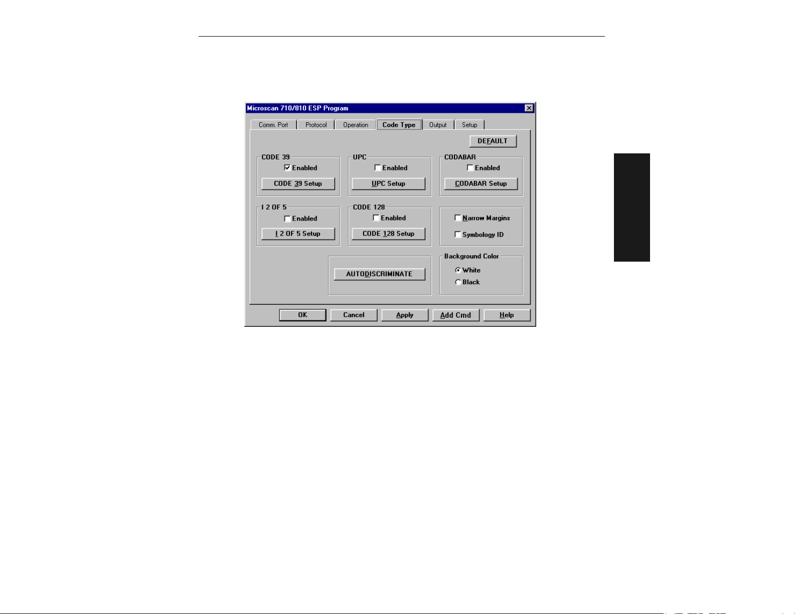
Code Type Menu
2–Menu Config.
Figure 2-8 Code Types Menu Structure
Default
Clicking the DEFAULT button will reset all parameters on the current menu to
defaults. This does not take effect until it is saved to the scanner with the SEND/NO
SAVE or SEND/SAVE buttons.
Code 39
Default: Enabled
Options: Enabled, Disabled
Check Digit
Default: Disabled
Options: Disabled, Enabled
Code 39 is self-checking and does not normally require a check digit. However, for
additional data integrity, a Modulus 43 check digit can be added to the bar code message. With Check Digit and an External or Serial trigger option enabled (see “Trig-
MS-810 Industrial Scanner User’s Manual
2-25
Page 48

Chapter 2
gering Mode” on page 2-16), an invalid check digit calculation will cause a noread
message to be transmitted at the end of the read cycle.
Check Digit Output
Default: Disabled
Options: Disabled, Enabled
When enabled, the check digit character is sent along with the label data. When disabled, label data is sent without the check digit.
Large Intercharacter Gap
Default: Disabled
Options: Disabled, Enabled
Allows the scanner to read labels with gaps between bar code characters exceeding
three times the narrow element width.
2–Menu Config.
Fixed Code Length
Default: Disabled
Options: Disabled, Enabled
Used to increase data integrity by ensuring that only one label length will be accepted.
Code Length
Default: 10
Options: 1 to 64
Note: Fixed Code Length must be enabled for Code Length to take effect.
Allows you to specify the exact number of characters that the scanner will recognize
(this does not include start and stop). The scanner will ignore any code not having the
specified length.
Codabar
Default: Disabled
Options: Disabled, Enabled
Start & Stop Match
Default: Enabled
Options: Enabled, Disabled
Requires the Codabar start and stop characters (a, b, c, or d) to match before a valid
read can occur.
2-26
MS-810 Industrial Scanner User’s Manual
Page 49

Code Type Menu
Start & Stop Output
Default: Enabled
Options: Enabled, Disabled
Allows the start and stop characters to be transmitted with bar code data.
Large Intercharacter Gap
Default: Disabled
Options:Disabled, Enabled
Allows the scanner to read labels with gaps between bar code characters exceeding
three times the narrow element width.
Fixed Code Length
Default: Disabled
Options: Disabled, Enabled
Used to increase data integrity by ensuring that only label length will be accepted.
Code Length
Default: 10
Options: 1 to 64
Fixed Code Length must be enabled for Code Length to take effect.
:
Note
Allows you to specify the exact number of characters that the scanner will recognize.
The scanner will ignore any code not having the specified length.
Note: Setting Code Length to any number less than 4 will produce undetermined
results.
2–Menu Config.
Check Digit
Default: Disabled
Options: Disabled, Modulus 16, NW 7, Both
Allows you to select the type of checksum system Codabar will use.
Check Digit Output
Default: Disabled
Options: Disabled, Enabled
When enabled, the check digit character is sent along with the label data. When disabled, label data is sent without the check digit.
MS-810 Industrial Scanner User’s Manual
2-27
Page 50

Chapter 2
Interleaved 2 of 5
Default: Disabled
Options: Disabled, Enabled
Because I 2 of 5 is a continuous code, it is prone to substitution errors. Hence, a code
length must be defined and a bar code label containing an even number of digits must
be used. It is also recommended that a Modulus 10 check digit be used to ensure the
best possible data integrity.
Check Digit
Default: Disabled
Options: Disabled, Enabled
I 2 of 5 uses a Modulus 10 check digit.
Check Digit Output
2–Menu Config.
Default: Disabled
Options: Disabled, Enabled
When enabled, the check digit character is sent along with the label data. When disabled, label data is sent without the check digit.
Code Length #1
Default: 10
Options: 0 to 64, even. If you enter an odd number the scanner will use the next
lower number.
With I 2 of 5, two code lengths can be defined. When using only one label length in an
application, we recommend setting Code Length #2 to 0 to ensure data integrity. If a
check digit is used, it must be included in the code length count.
Code Length #2
Default: 6
Options: 0 to 64, even. (If you enter an odd number the scanner will use the next
lower number.)
If using a second label, you may also specify a zero or any even code length from 2 to
30. If not using a second label, set Code Length #2 to 0 to ensure data integrity.
2-28
MS-810 Industrial Scanner User’s Manual
Page 51

Code Type Menu
UPC
Default: Disabled
Options: Disabled, Enabled
When enabled, the scanner will read UPC version A and UPC version E only.
EAN
Default: Disabled
Options: Disabled, Enabled
UPC must be enabled for EAN to take effect.
Note:
When EAN is enabled, the scanner will read UPC version A, UPC version E, EAN 13,
and EAN 8. It will also append a leading zero to UPC version A label information and
transmit 13 digits. If you do not want to transmit 13 digits when reading UPC version
A labels, disable EAN.
Supplementals
Default: Disabled
Options: Disabled, Enabled, Required
Allows the scanner to read supplemental bar code data that has been appended to the
standard UPC or EAN codes.
Enabled
When Supplementals is set to Enabled, the UPC main and supplemental label are considered to be separate labels. Therefore Number of Labels must be set to 2 and a multilabel separator will be inserted between the label data and the supplemental label
data.
For example, if Supplementals is enabled, Number of Labels is set to 2, and the Multilabel Separator Character is defined as a #, the data will be displayed as: LABEL #
SUPPLEMENTAL
If you are using two labels with Supplementals, set Number of Labels to 4.
Note: Under no circumstances will a supplemental label be output without a main label.
Note: Do not set Triggering Mode (page 2-16) to Continuous Read 1 Output. Enabling
Continuous Read 1 Output will cause Number of Labels to default to 1.
2–Menu Config.
Required
When set to Required, the UPC main and supplemental labels are considered to be one label. If
either the main or supplemental label is not read, a single noread message will be output.
For example, if Supplementals is set to Required, Separator is enabled, and an asterisk is defined as the Separator Character, then the data will be displayed as: LABEL *
SUPPLEMENTAL.
If set to disabled, the following will be displayed: LABEL SUPPLEMENTAL.
MS-810 Industrial Scanner User’s Manual
2-29
Page 52

Chapter 2
Note: If additional labels—other than the main or supplemental—will be read in the
same read cycle, Number of Labels should be set accordingly.
Separator
Default: Disabled
Options: Disabled, Enabled
Allows you to insert a character between the standard UPC or EAN code and the supplemental code when Supplementals is set to Required.
Separator (character)
Default: , (comma)
Options: Any ASCII character.
Allows you to change the separator character from a comma to a new value.
Note: UPC separator character, if used, must be different than the multilabel separator.
2–Menu Config.
Code 128
Default: Disabled
Options: Disabled, Enabled
Fixed Code Length
Default: Disabled
Options: Disabled, Enabled
Allows you to increase data integrity by ensuring that only one label length will be
accepted.
Code Length
Default: 10
Options: 1 to 64
Fixed Code Length must be enabled for Code Length to take effect.
Note
:
Allows you to specify the exact number of characters that the scanner will recognize. The
scanner will ignore any code not having the specified length.
Narrow Margins
Default: Disabled
Options: Disabled, Enabled
Allows the scanner to read bar codes with quiet zones less than 10 times the width of the
narrow bar element. “Quiet zone” is the space at the leading and trailing ends of a label.
Each quiet zone can be as narrow as only five times the width of the narrow bar element
when Narrow Margins is enabled.
2-30
MS-810 Industrial Scanner User’s Manual
Page 53

Code Type Menu
Symbology ID
Default: Disabled
Options: Disabled, Enabled
When enabled, the scanner reads and outputs a three character prefix:
1. ] (close bracket character) indicating the presence of a symbology ID
2. A, F, I, E, or C
A = Code 39; F = Codabar; I = I 2 of 5; E = UPC/EAN; C = Code 128
3. A single number indicating the status of the check digit character (table 2-1):
If check digit is not enabled, the output is 0 (Col. 1). If check digit and check digit
output are enabled, the output is as shown in column 2. If check digit is enabled, but
output is disabled (Col. 3), the output is as shown in Col. 4, which is the sum of Col. 2
and Col. 3.
Table 2-1 Symbology Identifier Option Values
2–Menu Config.
Column 1
No check
character
Code 39 0 1 (2) 3
Codabar 0 2 (4) 6
I 2 of 5 0 1 (2) 3
UPC/EAN
Code 128
Column 2
Check digit
and
output
enabled
Always zero, do not follow AIM spec.
Column 3
Check digit
output
disabled
Column 4
Sum of
Column
2 and 3
Example 1: For Code 39, if check digit and check digit output are both enabled, a 1
will be output; but if check digit output is disabled, a 3 (the sum of column 2 and column 3) will be output.
Example 2: For Codabar, if check digit and check digit output are both enabled, a 2 will be
output; but if check digit output is disabled, a 6 (the sum of 2 and 4) will be output.
Autodiscrimination
Default: Disabled
Options: Disabled, Enabled
When enabled, all symbology types are enabled.
MS-810 Industrial Scanner User’s Manual
2-31
Page 54

Chapter 2
Background Color
Default: White
Options: White, Black
Allows the scanner to be set to read symbols on white (light) or black (dark) backgrounds.
2–Menu Config.
2-32
MS-810 Industrial Scanner User’s Manual
Page 55
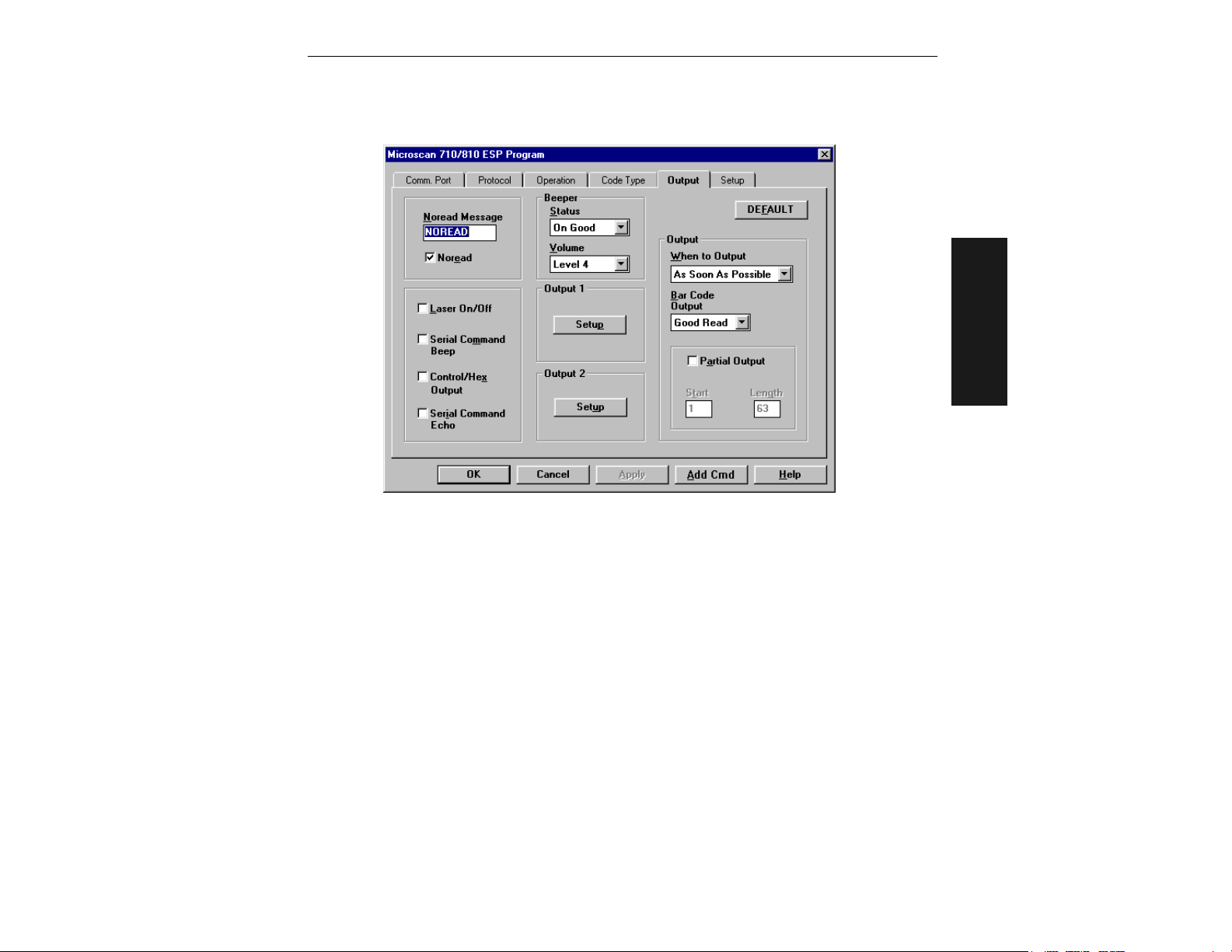
Output Menu
Output Menu
Figure 2-9 Scanner Output Menu Structure
Default
Clicking the DEFAULT button will reset all parameters on the current menu to
defaults. This does not take effect until it is saved to the scanner with the SEND/NO
SAVE or SEND/SAVE buttons.
Note: Bar code output data and noread messages are transmitted on pin 2 under
conditions set principally in Bar Code Output.
2–Menu Config.
Relay-1 and Relay-2
Relay pulses are transmitted via pins 7 and 14 (Relay-1 and Relay-2, respectively)
and individually configured under conditions set in Relay-1 and Relay-2.
Note: Relay-1 output also causes closure of a relay in the IB-105 box, accessible
through pin 15 of the IB-105 host connector only in the 5 V version (see table A-9
on page A-23).
Relay-1 and relay-2 can allow simultaneous output under individually programmed
conditions.
MS-810 Industrial Scanner User’s Manual
2-33
Page 56

Chapter 2
Output On
Default: Mismatch or Noread
Options: Mismatch or Noread, Match, Mismatch, Noread
If Output On is set to Mismatch or Noread, Match, or Mismatch, a relay pulse
Note
:
will not output unless Match Code Type (page 2-22) is not disabled and a master
label is downloaded into memory (page 2-21).
Note: To send a pulse on a Good Read, enable Match and disable Match Code Type
(see “Match Code Type” on page 2-22).
Allows you to set the conditions that will output a relay pulse either to pin 7 (Relay-1) or
to pin 14 (Relay-2).
Mismatch or Noread
Sends a pulse when the label's data does not match that of the master label or the
label is not decoded before the end of the read cycle.
Match (or Good Read)
2–Menu Config.
Sends a pulse when the decoded label matches the master label. (To send the pulse
on a good read, disable Match Code Type on page 2-22.)
Mismatch
Sends a pulse when the label’s data does not match that of the master label.
Noread
Sends a pulse when the label’s data is not decoded before the end of the read cycle.
Polarity
Default: Negative
Options: Negative, Positive
Allows you to choose between positive and negative output signals for the relay output pin that is enabled.
Pulse Width (in 10 ms incs)
Default: 5 (.05 seconds). Corresponds to 50 ms displayed in the menu.
Options: 0 to 255 (0 to 2.55 seconds). Divide the number to be entered by 100 for
time in seconds.
Allows you to set the duration of the good match/noread output signals at the relay
output pin that is enabled.
Note: After completing changes to Output On, Polarity, and Pulse Width, press M to
advance to Bar Code Output and continue scrolling through the Scanner Output
options.
2-34
MS-810 Industrial Scanner User’s Manual
Page 57

Output Menu
# Before Output
Default: 1
Options: 1 to 255
Allows you to determine the number of consecutive hits (matches, mismatches, or
noreads as configured by Output On) that must occur before a relay pulse will be sent
from Relay-1 or Relay-2.
For example, if # Before Output is set to 3 and Relay-1 is set to Noread, then relay-1
will not fire until 3 consecutive noreads have occurred.
Note: The hits must be consecutive and each one must match the configured Output On condition. Any interruption in the consecutive sequence will result in a reset
and cause the scanner to start the count over.
Bar Code Output
Default: Good Read
Options: Good Read, Disabled, Match, Mismatch
Note: If Bar Code Output is set to Match or Mismatch, label data will not output
unless Match Code Type (page 2-22) is enabled and a master label is downloaded
into memory (page 2-21).
Allows you to choose the conditions under which label data (or noread messages) will
be sent to the host.
Good Read
The scanner outputs on any good read independent of how Match Code Type is set.
2–Menu Config.
Disabled
The scanner does not output both label data and noread messages to the serial port.
Match (with Match Code Type enabled)
The scanner outputs when the label data information matches the master label. However, if Match Code Type is disabled it outputs on any good read.
Mismatch (with Match Code Type enabled)
The scanner outputs when the label data information does not match the master
label. However, if Match Code Type is disabled it outputs on any good read.
When to Output (bar code data)
Default: As Soon As Possible
Options: As Soon As Possible, End of Read Cycle
Allows you to choose when bar code data is sent to the host.
As Soon As Possible
Causes bar code data (good reads) to be transmitted immediately upon a good
decode.
MS-810 Industrial Scanner User’s Manual
2-35
Page 58

Chapter 2
End of Read Cycle
Causes bar code data output to be delayed until the end of the read cycle.
Noread Message
Default: NOREAD
Options: Up to seven ASCII characters (except NUL)
Allows you to define any combination of ASCII characters (except NUL) up to seven
characters as the noread message. When enabled, and if no bar code label has been
decoded before timeout or the end of the read cycle, the noread message will be transmitted to the host.
Noread Output (enable/disable)
Default: Enabled
Options: Enabled, Disabled
Note: If Noread Output is enabled, the noread message will only output if Bar Code
2–Menu Config.
Output (page 2-35) is also enabled.
Allows you to enable or disable the noread message.
Beeper Status
Default: On Good
Options: On Good, On Noread
A beep is emitted either after each good read of a bar code label or after each noread.
Note: The beep period is short for triggered modes when a new trigger occurs imme-
diately or the output is delayed to the end of the read cycle on edge and serial triggers.
Beeper Volume
Default: Level 4
Options: Level 4, Level 5, Off, Level 1, Level 2, Level 3
Laser On/Off
Default: Disabled
Options: Disabled, Enabled
Note: A serial or external trigger (see “Triggering Mode” on page 2-16) must be
enabled for Laser On/Off to take effect.
When enabled, the laser is ON only during the read cycle. When disabled, the laser
operates continuously.
Note: Laser On/Off does not relate to the Enable Laser Scanning (<H>) or Disable
Laser Scanning (<I>) operational commands on page 4-6.
2-36
MS-810 Industrial Scanner User’s Manual
Page 59

Output Menu
K Command Options
Echo K Command
Default: Disabled
Options: Disabled, Enabled
When enabled, serial configuration commands (“K” commands) will be processed and
the new string for that command will be echoed back to the host. If an invalid command is sent to the host, the scanner will echo back the current setting of that command. For example, if the current Noread Message is “NOREAD” and
<Kk1,NONSENSE> is entered, the scanner will echo back: <Kk1,NOREAD>. In this
example the attempted entry “NONSENSE” exceeds the maximum allowable seven
characters. Therefore it is rejected and the current NOREAD message is echoed back
and remains the Noread Message.
Note: It is important to note that if a command with multiple fields is processed,
some of the fields may have been processed properly following an “invalid” command.
These changes will be in the string echoed back so that the user will know what did or
did not change.
Beep on K
Default: Disabled
Options: Disabled, Enabled
When enabled, the scanner beeps once whenever a K command is entered to indicate that the
command was accepted and processed. If an invalid command is entered, the scanner beeps 5
times to indicate an invalid entry. However, this does not necessarily mean that all data fields
have been entered incorrectly. Only one bad field needs to be found in order to activate the 5
beep response.
2–Menu Config.
Control Character Output
Default: Ctrl
Options: Ctrl, Hex
Determines response to an Echo K or status request command. When set to CTRL,
ASCII control character output includes a control character as shown in the “Ctrl” column of Table A-4, “ASCII Table with Control Characters,” on page A-10. When
set to Hex, the output is the actual character.
MS-810 Industrial Scanner User’s Manual
2-37
Page 60

Chapter 2
Partial Output
Default: Disabled
Options: Disabled, Enabled
When enabled, allows you to pre-select portions of labels to be transmitted by the
scanner.
In multilabel mode, partial output is performed on each separate label. For example, if
Start Position is set to 3 and Partial Length is set to 5, the following labels are transmitted as follows:
1234567890 as “34567”
1234 as “34”
1234,abcde as “34,cde” (two labels with separator)
12 as ““
Start Position
2–Menu Config.
Default: 1
Options: 1 to 63
Allows you to determine the first character from the beginning of a label to transmit.
Partial Length
Default: 63
Options: 1 to 63
Allows you to determine the number of characters to be transmitted.
2-38
MS-810 Industrial Scanner User’s Manual
Page 61
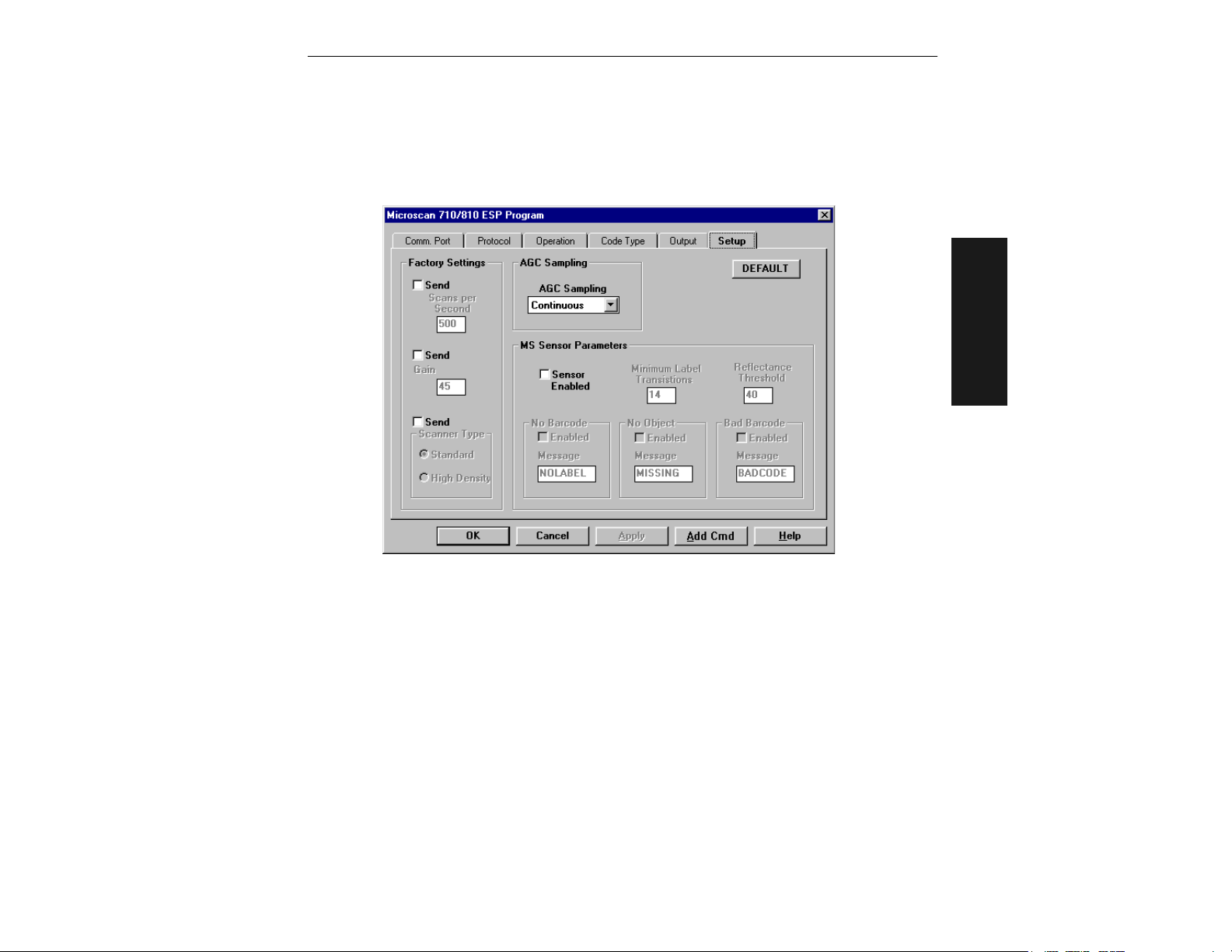
Setup Menu
Setup Menu
The Setup menu allows you to set specific bar code scanning parameters that affect
decode rate, and if equipped with the MS-sensor, allows you to determine why the
scanner did not decode a specific label within the triggered read cycle.
2–Menu Config.
Figure 2-10 Setup Menu Structure
Default
Clicking the DEFAULT button will reset all parameters on the current menu to
defaults. This does not take effect until it is saved to the scanner with the SEND/NO
SAVE or SEND/SAVE buttons.
Note: Unlike most configuration settings Scanner Type, Scans per Second, and Gain
Adjustment are not saved for power-on (but are initialized) when you press Y. To save
new settings to NOVRAM for these parameters, enter the <Zp> command. See “Save
Scanner Type, SPS, and Gain for Power-on” on “Save Scanner Type, SPS, and Gain
for Power-on,” on page 4-12.
MS-810 Industrial Scanner User’s Manual
2-39
Page 62

Chapter 2
Factory Settings
Scans per Second
Default: 40 (400 scans per second) for the Low Density and High Density and 50 (500
scans per second) for Standard Density.
Options: 30 to 80. Multiply the number to be entered by 10 for actual scans per second.
Allows you to set the number of scans per second by controlling mirror motor speed.
The range is 300 to 800 scans per second.
Gain Adjustment
Default: 45 (nominal, unit specific, optimized at the factory before shipment)
Options: 10 to 255
Allows you to specify a gain value for the analog circuitry. Changes to Gain should
typically be done by qualified technicians.
Important: Before saving any changes to Gain Adjustment (see “Save Scanner Type,
2–Menu Config.
SPS, and Gain for Power-on” on “Save Scanner Type, SPS, and Gain for
Power-on,” on page 4-12), first record the optimized factory setting for future ref-
erence.
Scanner Type
Default: Standard if the unit is configured for low density; High Density if the unit is
configured for high density.
Options: Standard, High Density
The Scanner Type “default” from the factory indicates the density type of the scanner
(with the unit’s optics adjusted accordingly). Do not change this setting unless instructed
to do so by a Microscan representative.
Important: Entering the <Zp> command (see “Save Scanner Type, SPS, and
Gain for Power-on” on page 4-12) will save the current setting for Scanner Type
to NOVRAM. If you need to verify the density type of a unit, see your FIS number and
contact your Microscan representative.
AGC Sampling
Default: Continuous
Options: Continuous, Disabled, Leading Edge
Allows you to specify how automatic gain control sampling will be done. Continuous
mode continually samples 14 transitions and stores the highest value of the samples
and adjusts the AGC value at the end of the scan. Leading Edge mode finds the leading edge by looking for a 40 µs quiet zone followed by 14 transitions and stores the
highest value of the samples and adjusts the AGC at the end of the scan. Leading
Edge is especially effective when labels are skewed. Changes to AGC Sampling should
typically be done by qualified technicians.
2-40
MS-810 Industrial Scanner User’s Manual
Page 63

Chapter
Serial
3
Configuration
3–Serial Config.
Chapter Contents
About Serial Configuration ..............................................................3-3
Communications Port Commands ...................................................3-5
Protocol Commands ........................................................................3-6
Operations Commands .................................................................3-10
Code Types Commands ................................................................3-13
Scanner Output Commands ..........................................................3-16
Scanner Setup Commands ...........................................................3-19
Most of the configuration changes to the scanner that can be made in the menu can
also be accomplished by command strings from the host.
Serial command strings are entered from an ASCII terminal. As with menu configuration commands, serial configuration commands relate to the initial scanner setup.
To quickly reference the serial configuration commands, see table 3-1 on page 3-2.
MS-810 Industrial Scanner User’s Manual
3-1
Page 64

Chapter 3
Table 3-1 Summary of Serial Configuration Commands
Function K Command Format
Comm.
Port
Protocol
Opera-
tions
Code
Types
3–Serial Config.
Scanner
Output
Scanner
Setup
All
Ka Host Port <Kabaud,parity,stop bits,data bits>
Ky Aux Port
KT Communications Status Request <KT?>
Kf Communications Protocol <Kfprotocol,address>
Kd Preamble <Kdstatus,ASCII characters>
Ke Postamble <Kestatus,ASCII characters>
Kc LRC <Kcstatus>
KA Response Timeout <KAtimeout setting>
KB Intercharacter Delay <KBnumber>
Kg Triggering Mode <Kgmode,filter time>
Kh End of Read Cycle <Khmode,time>
Ki Serial Trigger Character <Kicharacter>
Kj External Trigger Level <Kjmode>
Km Good Decode Reads <Kmnumber>
Kn Match Code Type
Kz New Master Pin <Kzstatus>
KL Number of Labels <KLnumber of labels,multilabel separator>
KV Operations Status Request <KV?>
Ko Narrow Margins/Symbology ID <Konarrow margins status,symbology ID status>
Kp Code 39
Kq Codabar
Kr Interleaved 2 of 5 <Krstatus,check digit,check digitoutput,length 1,length 2>
Ks UPC/EAN
Kt Code 128 <Ktstatus,fixed length,length>
Kx Background Color <Kxbackground color>
Ko Narrow Margins/Symbology ID <Konarrow margins status,symbology ID status>
P Autodiscriminate All Codes <P>
KW Code Types Status Request <KW?>
Kv Relay-1 <Kvoutput on,polarity,pulse width,# before output>
Kw Relay-2 <Kwoutput on,polarity,pulse width,# before output>
Kl Bar Code Output <Klstatus,when to output>
Kk Noread Message <Kkstatus,output>
Ku Beeper <Kustatus,volume>
KC Laser On/Off <KCstatus>
KS Serial Verification
KY Partial Output <KYstatus,start position,length>
KX Scanner Output Status Request <KX?>
KP Scanner Type <KPdensity>
KE Scans per Second <KEspeed>
KD Auto Gain Control <KDgain adjustment,AGC sampling>
KU Scanner Setup Status Request <KU?>
K? Return All K Commands <K?>
<Kymode,baud,parity,stop bits,data bits,daisy chain status,daisy
chain id>
<Kntype,sequential matching,match start position,match length,wild
card character,sequence on noread,sequence on every mismatch>
<Kpstatus,check digit status,check digit output status,large interchar-
acter gap,fixed code length status,code length>
<Kqstatus,start & stop match status,start & stop output status,large
intercharacter gap,fixed code length status,code length,check digit
type,check digit output>
<Ksstatus,EAN status,supplementals
status,separator status,separator char.>
<KSserial command echo status,serial command beep status,control/hex
output>
3-2
MS-810 Industrial Scanner User’s Manual
Page 65

About Serial Configuration
About Serial Configuration
Serial Configuration Command Format
The format for a serial configuration command is,
<Kparameterdata,data,...etc.><initializing command>
Where:
• Less than < and greater than > symbols are included as part of the commands.
• “parameter,” as used here, are those character(s) that precede the data.
• The “initializing command” <A> or <Z> is sent after configuration is complete. <Z>
resets and saves for power up. <A> initializes the change to RAM.
mation, see “Reset,” on page 4-11.)
For example, the following command enables UPC and saves the change for power-on:
<Ks1><Z>.
1
(For more infor-
When using serial configuration commands, note also the following conventions:
• Parameters and data are “case sensitive.” That is, characters must be entered as
upper or lower case, as specified.
• All data fields (except the last) must be followed by a comma (without a space).
• If there is no change in a given field, then commas can be entered alone, or with the
existing data (for example, <Ka,,,0> or <Ka4,1,0,0>).
• All fields preceding the modified field must be included. For example, in Host Port, to
change Data Bits to Eight without changing any other field, send either: <Ka,,,1> or
<Ka4,1,0,1>.
• All fields following the modified field can be left out. For example, in the RS-232 port,
to change Baud Rate to 4800, send <Ka3>.
(See examples on following pages.)
1. See “Initializing serial configuration commands” on page 3-4 for definitions and examples.
MS-810 Industrial Scanner User’s Manual
3-3
3–Serial Config.
Page 66

Chapter 3
Initializing serial configuration commands
To ensure that a serial configuration command will take effect, you need to follow it with one
of the operational commands below:
<A>
To reset
<Z>
To reset
For example, to change Baud Rate and reset without saving changes for power-up, send
<Ka3><A>.
To change Baud Rate and reset, saving the changes to NOVRAM, send <Ka3><Z>.
To
ensure that a command was received and accepted, you can send the Show Scanner
Status command, <?>.
but not save changes for power-on.
and save changes for power-on.
Concatenating Serial Commands
Commands can be concatenated (added together) to a maximum of 64 characters in a
single string or data block. Additional data blocks of 64 or less characters can be sent
provided there is at least a 10 ms pause between blocks.
For example, <Kc1><Kh1><Ko1><A> enables LRC, sets End of Read Cycle mode
to New Trigger, enables Narrow Margins and resets the data buffers (without saving the
changes for power-on).
Serial Command Status Request
The status of serial commands can be requested by entering the command followed by a
question mark. For example, send <Ke?> to request the status of Postamble. Commands KT?, KV?, KW?, KX?, and KU? are used to request the status of groups of serial
3–Serial Config.
commands (see table 3-1 on page 3-2).
Loss of Communications
Making changes to communications parameters such as Baud Rate, Parity, Stop Bits,
LRC, etc. without corresponding changes in linked device(s) can result in the loss of
menu access. If this should occur, default the scanner with the <Zd> Restore/Save
Default Configuration for Power-on command as described on page 4-12.
CAUTION: Defaulting the scanner will reset all standard configuration parameters except
Scanner Type, Scans per Second, and Gain Adjustment to their original default values.
Note: Power must be available to the scanner during the default procedure.
3-4
MS-810 Industrial Scanner User’s Manual
Page 67

Communications Port Commands
Communications Port Commands
Host Port
Note: Changes made in the scanner’s communications parameters such as baud rate,
parity, stop bits, LRC, etc., must be matched in the other device(s) or communications
will be lost. If this occurs, default the scanner with the <Zd> Restore/Save Default
Configuration for Power-on command as described on page 4-12.
Format: <Kabaud rate,parity,stop bits,data bits>
baud rate:
0 = 600 3 = 4800 6 = 38.4K
1 = 1200 4 = 9600 7 = 76.8K
2 = 2400 5 = 19.2K 8 = 300
stop bits:
0 = One
1 = Two
parity:
0 = None
1 = Even
2 = Odd
data bits:
0 = Seven
1 = Eight
3–Serial Config.
Example: To c
hange Host Port Baud Rate to 2400, send
<Ka2>
.
Auxiliary Port
Format: <Kymode,baud rate,parity,stop bits,data bits,daisy chain ID status,daisy
chain id>1
mode:
0 = Disabled
1 = Transparent
2 = Half duplex
parity:
0 = None
1 = Even
2 = Odd
Example: To change Aux Port Baud Rate to 2400, send <Ky2>.
3 = Full duplex
4 = Daisy chain
stop bits:
0 = One
1 = Two
baud rate:
0 = 600 3 = 4800 6 = 38.4K
1 = 1200 4 = 9600 7 = 76.8K
2 = 2400 5 = 19.2K 8 = 300
data bits:
0 = Seven
1 = Eight
daisy chain ID
status
0 = Disabled
1 = Enabled
daisy chain I.D.
any 2 ASCII
characters.
Default is 1/
Communications Status Request
Format: <KT?>
Returns status of each command in the group.
1. For use with Microscan’s IB-105.
MS-810 Industrial Scanner User’s Manual
3-5
Page 68

Chapter 3
Protocol Commands
If selecting one of the options from 0 to 4 (Point-to-Point, Point-to-Point with RTS/CTS,
Point-to-Point with XON/XOFF, Point-to-Point with RTS/CTS and XON/XOFF, or Polling
Mode D), use this format:
Format: <Kfprotocol>
protocol:
0 = Point-to-Point
1 = Point-to-Point with RTS/CTS
2 = Point-to-Point with XON/XOFF
3 = Point-to-Point with RTS/CTS
and XON/XOFF
Example: To change the Protocol to Polling Mode D, send <Kf4>.
If selecting Multidrop (5), you must define an address and append it to the command
string.
Format: <Kf5protocol,address>
protocol:
5 = Multidrop
Example: To change the Protocol to Multidrop with an address of 33, send <Kf5,33>.
If selecting User Defined (6) or User Defined Multidrop (7), complete the format by
3–Serial Config.
either choosing new parameters or concatenating unchanged data fields (separate by
commas).
TIP: For User Defined, first select Point-to-Point <Kf0> and then User Defined
<Kf6...>. For user Defined Multidrop, first select Multidrop <Kf5>, then User Defined
Multidrop <Kf7...>.
Format: <Kfprotocol,RES,address,REQ,EOT,STX,ETX,ACK,NAK,from host>
1
4 = Polling Mode D
5 = Multidrop (requires address)
6 = User Defined
7 = User Defined Multidrop
address:
Any number from 1 to 50
protocol:
6 = User Defined;
From Host: 0 = disabled 1 = enabled
1. Polling Mode D, Multidrop, User Defined, and User Defined Multidrop are for use with Micros-
can’s IB-105.
3-6
MS-810 Industrial Scanner User’s Manual
Page 69
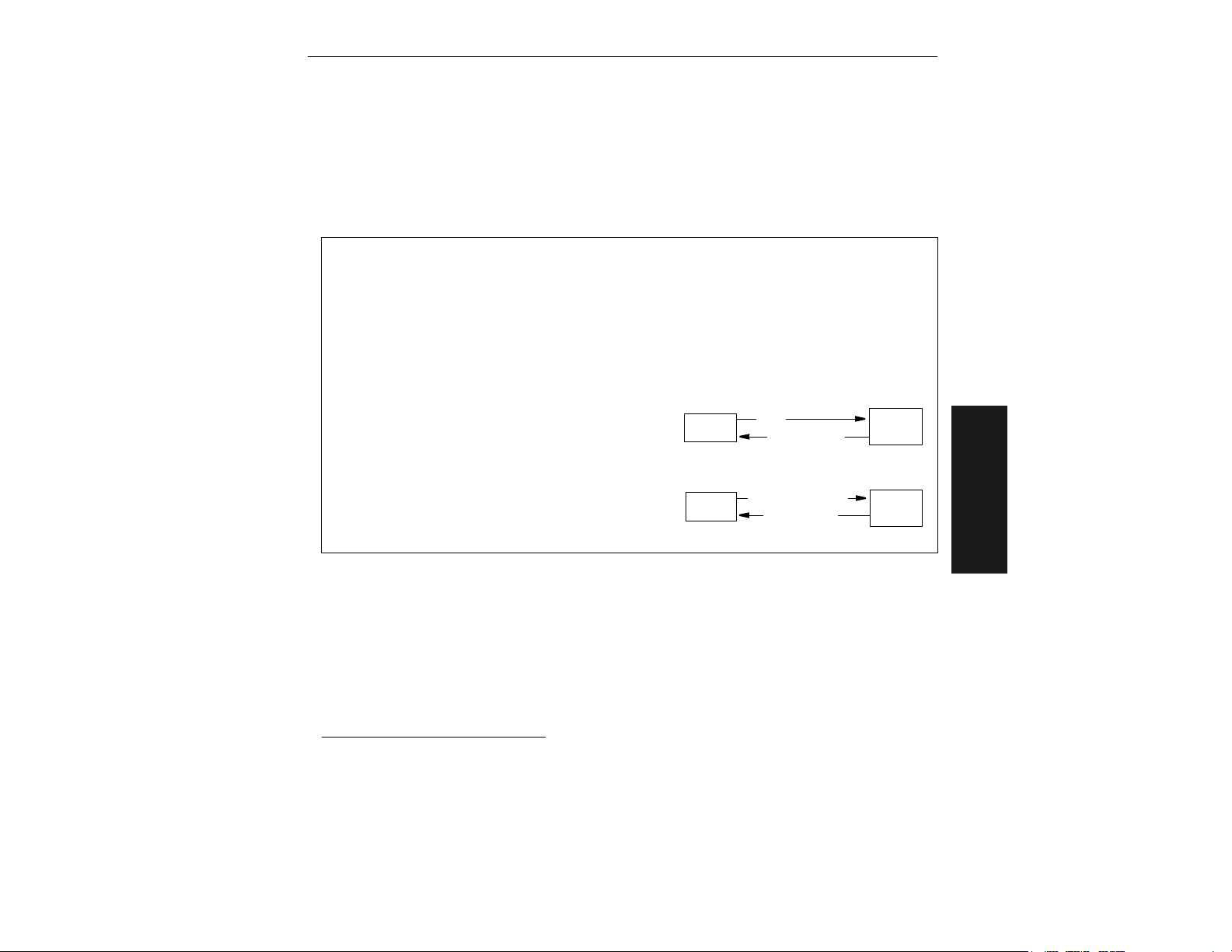
Protocol Commands
Example:
send
To select an unpolled ACK/NAK User Defined protocol with LRC disabled,
<Kf0><Kf6,,,,,,,^F,^U><Kc0>
.1 ACK and NAK will be displayed in the
menu.
Note: Address, can be assigned any ASCII character except a null. Control characters are
used to define RES through NAK (except Address). Table 3-2 lists the control characters
used for these data fields. (Refer to Table A-4, “ASCII Table with Control Characters,” on
page A-10 for more information.)
Explanation of the From Host option
Suppose STX, ETX and EOT are defined in the MS-810, the trigger counter is currently T/
00000, and you want to send the Trigger Counter Request command to the scanner.
Defined Protocol: STX, ETX, EOT
Trigger Counter Status: T/00000
Host Command Request: <T> (Trigger Counter Request Command)
The command string format from the host would depend on the From Host setting.
If From Host is disabled, <T> (Trigger Counter
Request command) would be the required format
from the host to cause the scanner to return STX T/
00000 ETX EOT. However, if From Host is enabled,
the required host command string would be
STX
From Host Disabled
HOST
<T>
STX T/00000
ETX EOT
MS-810
<T> ETX EOT to receive the same response
from the scanner. In either case the data string
returned by the scanner always includes the defined
protocol. In this example, that returned data would
be STX T/00000 ETX EOT.
From Host Enabled
HOST
STX <T> ETX EOT
STX T/00000
MS-810
ETX EOT
3–Serial Config.
Format: <Kf protocol, RES, address, REQ, EOT, STX, ETX, ACK, NAK>
protocol:
7 = User Defined Multidrop
Example: To select an unpolled ACK/NAK User Defined protocol with LRC disabled,
<Kf0><Kf6,,,,,,,^F,^U><Kc0>
send
3
menu.
.2 ACK and NAK will be displayed in the
Note: Address, can be assigned any ASCII character except a null. Control characters are
used to define RES through NAK (except Address). Table 3-2 lists the control characters
1. <Kf0> nulls the address and <Kc0> disables LRC. A control character, although conventionally
represented here and in the ASCII table on page A-10 as two characters (^F or ^U, etc.), is actually a single ASCII character that is entered on the keyboard by holding down the control key
while pressing the desired letter.
2. <Kf0> nulls the address and <Kc0> disables LRC.
3. A control character, although conventionally represented here and in the ASCII table on page
A-10 as two characters (^F or ^U, etc.), is actually a single ASCII character that is entered on
the keyboard by holding down the control key while pressing the desired letter.
MS-810 Industrial Scanner User’s Manual
3-7
Page 70
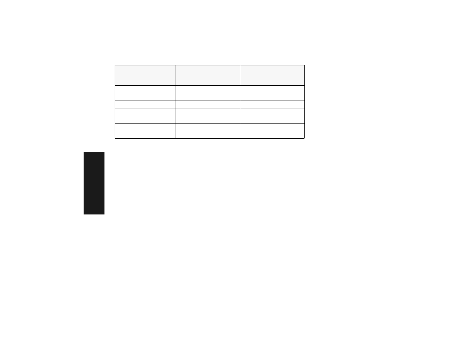
Chapter 3
used for these data fields. (Refer to Table A-4, “ASCII Table with Control Characters,” on
page A-10 for more information.)
Table 3-2 Protocol Commands
Protocol Command
(Mnemonic displayed on
Microscan menu)
RES ^D Reset
REQ ^E Request
EOT ^D Reset
STX ^B Start of Text
ETX ^C End of Text
ACK ^F Acknowledge
NAK ^U Negative Acknowledge
Control Characters
(Entered in menu or
serial command)
Effect of Command
Preamble
Format: <Kdstatus,preamble character(s)>
status:
0 = Disabled
1 = Enabled
preamble character(s):
Enter one or two preamble characters except a null
(00H). Default is ^M.
Example: To enable Preamble with just one character, an FF (form feed), send <Kd1,^L>
3–Serial Config.
Postamble
Format: <Kestatus,postamble character(s)>
status:
0 = Disabled
1 = Enabled
postamble character(s):
Enter one or two postamble characters except a
null (00H). Default characters are ^M^J.
.
Example: To disable Postamble, send <Ke0>.
LRC
Format: <Kcstatus>
status:
0 = Disabled
1 = Enabled
Example: To enable LRC, send <Kc1>.
3-8
MS-810 Industrial Scanner User’s Manual
Page 71

Protocol Commands
Response Timeout
Format: <KAtimeout setting>
timeout setting:
Default is 12 (ms).
Any number from 0 to 65,000 (a zero causes an indefinite wait).
Example: To change Response Timeout to 30 ms, send <KA30>.
1
Intercharacter Delay
Format: <KBtime interval>
time interval (between characters in milliseconds):
Default is 0.
Any number from 0 to 255.
Example: To change Inter-character Delay to 30 ms, send <KB30>.
3–Serial Config.
1. For use with Microscan’s IB-105.
MS-810 Industrial Scanner User’s Manual
3-9
Page 72

Chapter 3
Operation Commands
Tri gg e r in g M o de
Format: <Kgtriggering mode,filter time>
triggering mode:
0 = Continuous Read
1 = Continuous Read 1 Output
2 = External Level
3 = External Edge
4 = Serial Data
5 = Serial Data & Edge
Example: To select External Edge, send <Kg3>.
End of Read Cycle
Format: <Khend of read cycle mode,timeout>
end of read cycle mode:
0 = Timeout
1 = New Trigger
2 = Timeout & New Trigger
3–Serial Config.
Example: To select Timeout and change the timeout value to 6 seconds, send
<Kh0,600>.
trigger filter time (in 128 µs
increments):
Default is 78 (9984 µs; approx. 10
ms)
Any number between 2 and 255.
timeout (in 10 millisecond increments):
Default is 100 (one second).
Any number between 0 and 65535.
Serial Trigger Character
Format: <Kiserial trigger character>
serial trigger character:
Default is ^].
Any available ASCII character (see “ASCII Table with Control Charac-
ters” on page A-10).
Example: To define the Serial Trigger Character as a lowercase c, send <Kic>.
1. Avoid selecting a serial trigger character that is also an operational command. For example, an
uppercase C cannot be used as a serial trigger character because it is the operational command
for Enter Decode Rate Test. However, a lowercase c could be used without initiating the decode
rate test.
3-10
MS-810 Industrial Scanner User’s Manual
1
Page 73

Operation Commands
External Trigger Level
Format: <Kjexternal trigger level>
external trigger level (initiates a read cycle):
0 = Negative
1 = Positive
Example: To change External Trigger Level to Negative, send <Kj0>.
Good Decode Reads
Format: <Kmnumber of reads>
number of reads (before a good decode):
Default is 1.
Any number from 1 to 31.
Example: To change Good Decode Reads to 3, send <Km3>.
Match Code Type
Format: <Kntype,sequential matching,match start position,match length,wild card
character,sequence on noread,sequence on every mismatch>
type:
0 = Disabled
1 = Enabled
2 = Wild Card
3 = Sequential
match length
Default is 1.
1 to 31
sequence on noread:
0 = Disabled 1 = Enabled
When enabled, the scanner sequences (increment or dec-
rement) on every noread.
sequence on every mismatch:
0 = Disabled 1 = Enabled
When disabled, if a mismatch is out of sequence by no
more than 1, then the sequence resumes and searches
indefinitely.
When enabled, the scanner sequences on every mismatch.
sequential matching
0 = Increment
1 = Decrement
wild card character
Default is *.
Any ASCII character.
match start position
Default is 0.
0 to 64
If 001, 002, noread, then
search for 003.
If 001, 002, noread, then
search for 004.
If 001, 002,
004 (mismatch), then
search for 005.
If 001, 002, mismatch,
then search for 004. If mismatch occurs again, then
search for 005, etc.
3–Serial Config.
MS-810 Industrial Scanner User’s Manual
3-11
Page 74

Chapter 3
Example: To enable Match Code Type for Sequential, set Sequential Matching for Decrement, and enable Sequence on Every Mismatch, send <Kn2,1,,,,,1>.
New Master Pin
Format: <Kzstatus>
status:
0 = Disabled
1 = Enabled
Example: To enable New Master Pin, send <Kz1>.
Number of Labels
Format: <KLnumber,multilabel separator>
number of labels:
Default is 1.
Any number from 1 to 6
Example: To change Number of Labels to 3, send <KL3>.
multilabel separator:
Default is ,.
Any valid ASCII character
Operations Status Request
Format: <KV?>
Returns status of each command in the group.
3–Serial Config.
3-12
MS-810 Industrial Scanner User’s Manual
Page 75

Code Type Commands
Code Type Commands
Code 39
Format: <Kpstatus,check digit status,check digit output status,large intercharacter
gap,fixed code length status,code length>
status:
0 = Disabled
1 = Enabled
large inter-character gap:
0 = Disabled
1 = Enabled
Example: To set Fixed Code Length to 30, send <K,,,,1,30> or <Kp1,0,0,0,1,30>.
check digit status:
0 = Disabled
1 = Enabled
fixed code length
status:
0 = Disabled
1 = Enabled
check digit output status:
0 = Disabled
1 = Enabled
code length:
Default is 10.
Any number from 1 to
64.
Codabar
Format: <Kqstatus,start & stop match status,start & stop output status,large
intercharacter gap,fixed code length status,code length,check digit type,check digit
output>
status:
0 = Disabled
1 = Enabled
arge inter-character gap:
l
0 = Disabled
1 = Enabled
check digit type:
0 = Disabled
1 = Mod 16
start & stop match status:
0 = Disabled
1 = Enabled
fixed code length status:
0 = Disabled
1 = Enabled
2 = NW7
3 = Both
start & stop output status:
0 = Disabled
1 = Enabled
code length:
Default is 10
Any number from 1 to 64.
check digit output:
0 = Disabled
1 = Enabled
3–Serial Config.
Example: To set Fixed Code Length to 9, send <Kq1,,,,1,9> or <Kq1,1,1,0,1,9>.
I 2 of 5
Format: <Krstatus,check digit status,check digit output status,code length #1,code
MS-810 Industrial Scanner User’s Manual
3-13
Page 76

Chapter 3
length #2>
status:
0 = Disabled
1 = Enabled
code length #1:
Default is 10.
Zero or any even
number from 2 to 64.
Example: To set Fixed Code Length #1 to 8 and Fixed Code Length #2 to 4, send
<Kr1,,,8,4> or <Kr1,0,0,8,4>.
check digit status:
0 = Disabled
1 = Enabled
code length #2:
Default is 6.
Zero or any even
number from 2 to 64.
check digit output status:
0 = Disabled
1 = Enabled
UPC/EAN
Format: <KsUPC status,EAN status,supplementals status,separator
status,separator character>
UPC status:
0 = Disabled
1 = Enabled
separator status:
0 = Disabled
1 = Enabled
3–Serial Config.
Example: To change Supplementals to Required, and change Separator Character to a
dash (–), send <Ks1,1,2,1,–>.
EAN status:
0 = Disabled
1 = Enabled
(UPC must also be enabled)
separator character:
Any ASCII character (except NUL).
Default is a comma (,).
supplementals status:
0 = Disabled
1 = Enabled
2 = Required
Code 128
Format: <Ktstatus,fixed code length status,code length>
status:
0 = Disabled
1 = Enabled
Example: To enable Code 128, enable Fixed Code Length, and set Code Length to 9,
send <Kt1,1,9>.
3-14
fixed code length status:
0 = Disabled
1 = Enabled
MS-810 Industrial Scanner User’s Manual
code length:
Default is 10.
Any number from 1 to 64.
Page 77

Background Color
Format: <Kxstatus>
status:
0 = White
1 = Black
Example: To enable Black for background, send <Kx1>.
White is the default background on bar code symbols.
Narrow Margins/Symbology ID
Format: <Konarrow margins status,symbology ID status>
Code Type Commands
narrow margins status:
0 = Disabled
1 = Enabled
Example: To enable Narrow Margins, send <Ko1>.
symbology ID status:
0 = Disabled
1 = Enabled
Autodiscriminate
Format: <P>
Enables all available symbology types and disables OMR. You may individually disable/
enable each symbology type also.
Note: For maximum scanning speed, enable only those symbologies used in the applica-
tion.
Code Types Status Request
Format: <KW?>
Example: Returns status of each command in the group
3–Serial Config.
MS-810 Industrial Scanner User’s Manual
3-15
Page 78

Chapter 3
Output Commands
Relay-1
Format: <Kvoutput on,polarity,pulse width,# before output>
output on (mode):
0 = Mismatch or Noread
1 = Match (or Good Read)
2 = Mismatch
3 = Noread
Example: To set Relay-1 to Mismatch and change Pulse Width to 40 ms, and # Before
Output to 5, send <Kv2,0,4,5> or <Kv2,,4,5>.
polarity:
0 = Negative
1 = Positive
pulse width:
Default is 5
(50 ms).
0 to 255
Relay-2
Format: <Kwoutput on,polarity,pulse width,# before output>
output on (mode):
0 = Mismatch or Noread
1 = Match (or Good Read)
2 = Mismatch
3 = Noread
polarity:
0 = Negative
1 = Positive
pulse width:
Default is 5
(50 ms).
0 to 255
# before
output:
Default is 1.
1 to 255
# before
output:
Default is 1.
1 to 255
Example: To set Relay-2 to Mismatch and change Pulse Width to 40 ms, send
3–Serial Config.
<Kw2,0,4> or <Kw2,,4>.
Bar Code Output
Format: <Klstatus,when to output>
status:
0 = Disabled
1 = Match
2 = Mismatch
3 = Good Read
Example: To set When to Output to End of Read Cycle, send <Kl3,1>.
3-16
when to output:
0 = As Soon As Possible
1 = End of Read Cycle
MS-810 Industrial Scanner User’s Manual
Page 79

Noread Message
Format: <Kkstatus,output>
Output Commands
status:
0 = Disabled
1 = Enabled
Example: To enable Noread Message and send the message “FAIL,” send
<Kk1,FAIL>.
noread output:
Default is NOREAD.
Any ASCII string up to 7 digits.
Beeper
Format: <Kubeeper status,beeper volume>
beeper status:
0 = On Good
1 = On Noread
Example: To set the beeper for On Noread and set the beeper volume to Off, send
<Ku1,0>.
beeper volume:
0 = Off 3 = Level 3
1 = Level 1 4 = Level 4
2 = Level 2 5 = Level 5
Laser On/Off
Format: <KCstatus>
status:
0 = Disabled1 = Enabled
Example: To enable Laser On/Off, send <KC1>.
3–Serial Config.
Partial Output
Format: <KYstatus,start position,length>
partial output status: start position: length:
0 = Disabled
1 = Enabled
Example: To enable Partial Output, set start position to 5, and set length to 6 characters, send <KY1,5,6>.
Default is 1
1 to 63
MS-810 Industrial Scanner User’s Manual
Default is 63
1 to 63
3-17
Page 80

Chapter 3
Serial Verification
Format: <KSserial command echo status,serial command beep status,control/hex
output>
serial command echo
status:
0 = Disabled
1 = Enabled
Example: To enable Serial Command Echo Status and Beep Status, and Hex output,
send <KS1,1,1>.
serial command beep
status:
0 = Disabled
1 = Enabled
control/hex output:
0 = Control
1 = Hex
Scanner Output Status Request
Format: <KX?>
Returns status of each command in the Scanner Output group.
3–Serial Config.
3-18
MS-810 Industrial Scanner User’s Manual
Page 81

Setup Commands
Setup Commands
Scanner Type
Important:
Power-on” on page 4-12) will save the current setting for Scanner Type to NOVRAM.
Format: <KPdensity>
scanner density type:*
0 = Standard
1 = High Density
* The “default” will depend on the type of scanner
Example: Do not change the scanner density type unless instructed to do so by a
Microscan representative.
Scans per Second
Format: <KEscans per second>
scans per second (in 10 millisecond increments):
Any number from 30 to 55.
Default is 50 (500 sps) for Standard, 40 for Low and High Density.
sending the <Zp> command (see “Save Scanner Type, SPS, and Gain for
.
3–Serial Config.
Example: To set the scanner to 400 scans per second, send <KE40>.
Auto Gain Control
Important: Before saving any changes to Gain Adjustment (see “Save Scanner Type,
SPS, and Gain for Power-on” on page 4-12), first record the optimized factory setting
for future reference.
Format: <KDgain adjustment,AGC samplings>
gain adjustment:
Default is 45 (nominal).
Any number from 10 to 255.
Example: To set the gain threshold to 40 and the AGC status to Leading Edge, send
<KD40,1,0>.
AGC sampling:
0 = Disabled
1 = Leading Edge
2 = Continuous
Scanner Setup Status Request
Format: <KU?>
Returns status of each command in the group.
MS-810 Industrial Scanner User’s Manual
3-19
Page 82

Chapter 3
3–Serial Config.
3-20
MS-810 Industrial Scanner User’s Manual
Page 83

Chapter
4
Utilities
Chapter Contents
Read Rate............................................................................................ 4-3
Trigger ................................................................................................. 4-5
Scanner ............................................................................................... 4-6
Counters .............................................................................................. 4-7
Master Label........................................................................................ 4-9
Reset ................................................................................................. 4-11
Checksum.......................................................................................... 4-13
Code Type Commands...................................................................... 4-15
The Utilities menu allows you to send operational commands to the MS-810 to carry out
routine operations “on the fly” as distinguished from serial configuration commands
that are generally used during your initial setup.
The Utilities menu can be accessed by clicking the Utilities button or selecting from the
Utilities pull down menu.
You can also send serial command strings to the scanner from a terminal window which
you access by Clicking Terminal in ESP. Serial commands are enclosed in brackets <>.
MS-810 Industrial Scanner User’s Manual
4-1
4–Utilities
Page 84

Chapter 4
Summary of Operational Commands
Type Cmd Result
<C>
<Cp>
Read Rate
Trigger
Scanner
Counters
Master Label
Reset
4–Utilities
Checksum
Code Types
(not in ESP)
<Cs>
<Cm>
<Ce>
<J>
char
<
>
<H>
<I>
<KE>
<KF>
<L1>
<L2>
<N>
<O>
<T>
<U>
<V>
<W>
<X>
<Y>
<E>
<F>
<G>
)XXXX)>Download Master Label Information
<
<)>
<))>
<A>
<Ad>
<An>
<D>
<Z>
<Zd>
<Zp>
<#>
<!>
<?>
<?1>
<P>
<Q>
<R>
<S>
Decode Rate Test for Single Label
Percentage Rate Test for Single Label
Multilabel Decode Rate Test
Multilabel Percentage Rate Test
Extended Decode Rate Test for Single or Multilabel
Exit any Rate Test
Serial Trigger Character
Enable Laser Scanning (Laser On)
Disable Laser Scanning (Laser Off)
Motor On
Motor Off
Relay-1 Pulse
Relay-2 Pulse
Noread Counter
Noread Counter Reset
Trigger Counter
Trigger Counter Reset
Match Code/Good Read Counter
Match Code/Good Read Counter Reset
Mismatch Counter
Mismatch Counter Reset
Enable Match Code Type
Disable Match Code Type
Store Next Label Scanned as Master Label
Request Master Label Information
Delete Master Label Information
Software Reset (does not save for power-on)
Software Reset/Restore Default
Software Reset/Read NOVRAM
Enter Configuration Mode
Software Reset/Save Parameters for Power-on
Restore/Save Default Configuration for Power-on
Save Scanner Type, SPS, and Gain for Power-on
Display Software Part Number
Display Checksum of EPROM
Show Scanner Status
Show Software Status (Send Status Byte, Part Number, and ROM Check-
sum. Display Current NOVRAM Checksum and Display NOVRAM Checksum at Power Up,)
Autodiscriminate All Codes
Enable Code 39 Only
Enable Codabar Only
Enable I 2 of 5 Only
4-2
MS-810 Industrial Scanner User’s Manual
Page 85

Read Rate
Read Rate
Decode (and percentage) rates can vary dramatically due to the angle and location of
the label in relation to the scan beam (or scan line, if using a scan head with a moving
beam). These tests are very useful in aligning and positioning the scanning device during installation.
Single Label Percent Test
Clicking Single Label Percent and Start instructs the scanner to output the percent of
decodes and any scanned label data.
Associated serial command: <Cp>
Single Label Decodes/Second Test
Clicking Single Label Decodes/Sec and Start instructs the scanner to output the
decodes per second and label data (if any). The decode rate can vary dramatically due
to the angle and location of the label in relation to the scan beam (or scan line, if using
a scan head with a moving beam). This test is very useful in aligning and positioning
the scanning device during installation.
Associated serial command: <C>
Multi-label Percent Test
Clicking Multi-label Percent and Start instructs the scanner to output the percentage
of scans decoded and label data (if any) for multiple labels.
Associated serial command: <Cm>
Multi-label Decode Rate Test
Clicking Multi-label Decode/Sec and Start instructs the scanner to output the
decode rate and label data (if any) for multiple labels.
Associated serial command: <Cs>
MS-810 Industrial Scanner User’s Manual
4–Utilities
4-3
Page 86
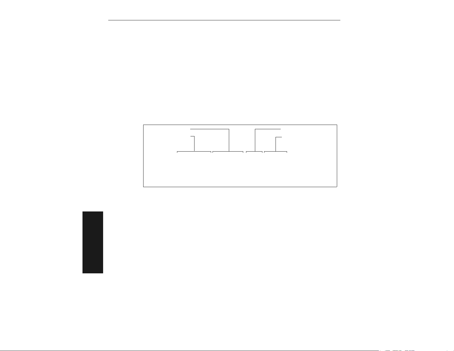
Chapter 4
End Read Rate Test
Clicking Stop ends both the Percent test and the Decodes/Second test for both single
and multi-label.
Associated serial command: <J>
Extended Mode
Choosing any of the Read Rate modes along with Extended Mode affects both single
and multiple labels. It instructs the scanner to output the transition data along with the
data from the latest test command sent. For example, enabling extended mode along
with single or multiple decodes per second will cause the decode rate, label data, and
transition data to be displayed.
Label Information
Decode Rate
per Second
347 Decodes/Sec 0071486026624 REF= 0 TRANS= 38
488 Decodes/Sec 0071486026624 REF= 0 TRANS= 37
488 Decodes/Sec 0071486026624 REF= 0 TRANS= 37
447 Decodes/Sec 0071486026624 REF= 0 TRANS= 33
* Example shows output when Postamble is enabled and defined as a carriage return and a line feed.
Associated serial command: <Ce> after <C>, <Cs>, <C>, or <Cs>
: The <Ce> command has no immediate effect if not preceded by <C>, <Cs>,
Note
<C>, or <Cs>.
4–Utilities
Reflectance Threshold
Number of Label Bar
4-4
MS-810 Industrial Scanner User’s Manual
Page 87

Trigger
Trigger
Clicking the Setup button will bring up the current trigger character. Next click Send to
send the trigger character to the scanner and initiate a read cycle. The results, a good
read or noread message, will be displayed on the blank screen below the button.
: Your scanner must be in a point-to-point protocol for Trigger Setup to work.
Note
: You can define the trigger character in the Operations menu.
Note
Associated serial command: <Ki serial trigger character>
MS-810 Industrial Scanner User’s Manual
4–Utilities
4-5
Page 88

Chapter 4
Scanner
Enable Laser Scanning
Clicking the Laser On button or sending serial command <H> will turn the laser on
continuously.
: Enable Laser Scanning does not relate to Laser On/Off command.
Note
Associated serial command: <H>
Disable Laser Scanning
Clicking Laser Off will turn the laser off. This feature is useful during extended periods
of time when no bar code labels are being scanned or the scanner is being configured.
Disabling laser scanning will not affect any downloaded commands to the scanner.
: Disable Laser Scanning does not relate to Laser On/Off command.
Note
Associated serial command: <I>
Motor On
Clicking Motor On or sending serial command <KE> turns the spinning mirror and raster mirror motors on (if not already running).
: Spinning mirror reaches full speed after a short time delay.
Note
Associated serial command: <KE>
Motor Off
Clicking Motor Off or sending serial command <KF> turns the spinning mirror motor
off. This command is useful for long idle periods.
Associated serial command: <KF>
4–Utilities
Output-1
Clicking Output #1 activates the output between pin 7 (regardless of Master Label or
Output-1 Driver status).
Associated serial command: <L1>
4-6
MS-810 Industrial Scanner User’s Manual
Page 89

Counters
Counters
Counter commands can be a numeric value from 00000 to 65,535. After reaching the
maximum numeric limit of 65,535, an error message will be displayed and the counter
will automatically rollover and start counting again at 00000. To obtain the cumulative
total of counts after the rollover has occurred, add 65,536 per each rollover (the scanner does not keep track of the number of rollovers) to the current count.
: All counter values will be lost if power is recycled to the scanner or the scanner
Note
receives a reset or save command.
Clicking Reset for any counter will reset that counter to 0.
Clicking Request for any counter will return the current number for that counter.
Noread Counter
Clicking Request displays the total number of noreads that have occurred since the last
reset.
Associated serial command: <N>
Noread Counter Reset
Clicking Reset sets Noread Counter to 00000.
Associated serial command: <O>
Tri g ge r Co u nt e r
Clicking Request displays the total number of triggers since the last reset.
Associated serial command: <T>
Trigger Counter Reset
Clicking Reset sets the trigger counter to 00000.
Associated serial command: <U>
Match Counter (or Good Read Counter)
Clicking Request displays the total number of good reads matching the master label or,
if Master Label is not enabled, the number of good reads since the last reset. This
MS-810 Industrial Scanner User’s Manual
4–Utilities
4-7
Page 90

Chapter 4
counter is always enabled, but will only work as a match count when Master Label is
enabled. If Master Label is not enabled, this counter records the number of good reads.
This count can be requested at any time.
Associated serial command: <V>
Match Counter Reset
Clicking Reset sets the Match Counter to 00000.
Associated serial command: <W>
Mismatch Counter
Clicking Request displays the message the number of labels successfully read that do
not match the master label since the last reset.
Associated serial command: <X>
Mismatch Counter Reset
Clicking Reset sets the Mismatch Counter to zero.
Associated serial command: <Y>
4–Utilities
4-8
MS-810 Industrial Scanner User’s Manual
Page 91

Master Label
Master Label
Enable Match Code Type
Identical to “Match Code Type,” on page 2-22. Instructs the scanner to compare bar
code labels being scanned with a master label and may under certain conditions send
out a relay driver signal and update internal counters.
If no master label has been entered, every decoded label will be a “mismatch” and will
increment the mismatch counter by one.
Enable Match Code Type is intended for use when the scanner is in a triggered mode. If
the Match Code Type is enabled in the Continuous Read mode, the scanner defaults to
Continuous Read 1 Output mode, and the label data must change before the scanner
will output data again, unless a timeout, if enabled, occurs. (See “Operation Menu” on
page 2-16.)
Associated serial commands: <E>
Disable Match Code Type
Disables Match Code Type.
Associated serial commands: <F>
Store Next Label Scanned as Master Label
If Match Code has been enabled, causes the scanner to read the next bar code label
scanned as the master label and stores it in RAM. All subsequently decoded labels are
compared against the new master label information. (See “Match Code Type” on page
2-22.)
Associated serial commands: <G>
Download Master Label Information
Downloads master label information into RAM from the host or a terminal. A stored
master label will not affect standard operation unless Match Code Type is enabled.
The Xs denote alphanumeric data, from 1 to 64 characters.
Associated serial commands: <)XXXX)>
MS-810 Industrial Scanner User’s Manual
4–Utilities
4-9
Page 92

Chapter 4
Request Master Label Information
Immediately sends the master label information to the host. To prevent conflicts with
outputting label data, first send the <I> command (Disable Laser Scanning (Laser
Off)).
Associated serial commands: <)>
Delete Master Label Information
Deletes master label information that has previously been loaded by either <)XXXX)>
Download Master Label Information Command or <G> Store Next Label as Master Label
command.
Associated serial commands: <))>
4–Utilities
4-10
MS-810 Industrial Scanner User’s Manual
Page 93
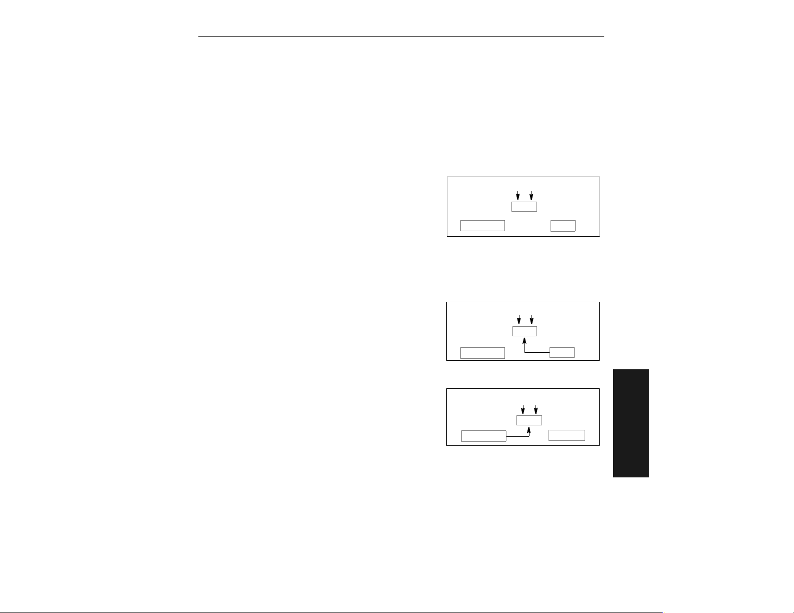
Reset
Important: All <A> and <Z> commands must be followed by a one second delay
before any operations, commands, or reads can be processed.
Reset
Reset
Initializes all serial configuration commands in
RAM and resets all counters and operating
parameters.
: Software Reset will reset all counters. You
Note
should record all data that you wish to save prior
to sending this command.
Associated serial command: <A>
Reset/Restore Default
Restores the ROM default values to RAM then initializes them. Does not effect Scanner Type,
Scans per Second, or Gain Adjustment.
Associated serial command: <Ad>
Reset/Read NOVRAM
Reads the NOVRAM settings then initializes them
to RAM.
Associated serial command: <An>
<A>
NOVRAM
<Ad>
<An>
NOVRAM
Initialize
RAM
Initialize
RAM
Initialize
RAM
ROM
ROMNOVRAM
4–Utilities
ROM
MS-810 Industrial Scanner User’s Manual
4-11
Page 94

Chapter 4
Reset/Save Parameters for Power-on
Allows you to save all configuration command settings to NOVRAM. Numeric counter values and master label data are not saved by this command.
1
Associated serial command: <Z>
Restore/Save Default Configuration for Power-on
Allows you to restore and save default settings for
all but Scanner Type, Scans per Second, and Gain
Adjustment to NOVRAM.
: Power must be available to the scanner
Note
during the default procedure.
Defaulting might be necessary after temporary changes or if communications between
the scanner and another device are lost or interrupted, or if you are using incompatible
equipment (for example, a terminal is set to communicate at 9600 baud, but the scanner is configured at 38.4K baud).
Associated serial command: <Zd>
<
Zd
NOVRAM
RAM
Save Scanner Type, SPS, and Gain for Power-on
Allows you to save the current settings for Scanner Type,
2
Scans per Second, and Gain Adjustment to NOVRAM. Once you send this command,
default values can only be recalled if you reenter
them individually and then save them again with
this command.
Important
This command will replace the optimized factory setting for Gain Adjust-
:
ment with your new setting; record and save this setting for future reference prior to
sending this command.
Associated serial command: <Zp>
<
Zp
RAM
4–Utilities
ROM
ROMNOVRAM
1. The <Z> Software Reset/Save Parameters for Power-on command can be executed at least
10,000 times. In normal usage this will exceed the life of the scanner. If frequent changes to
the operating parameters are required, it is recommended that the
only when the current configuration has been changed and the changes are to be permanent.
2. Scanner Type should not be changed from its factory setting.
4-12
MS-810 Industrial Scanner User’s Manual
<Z>
command be used
Page 95
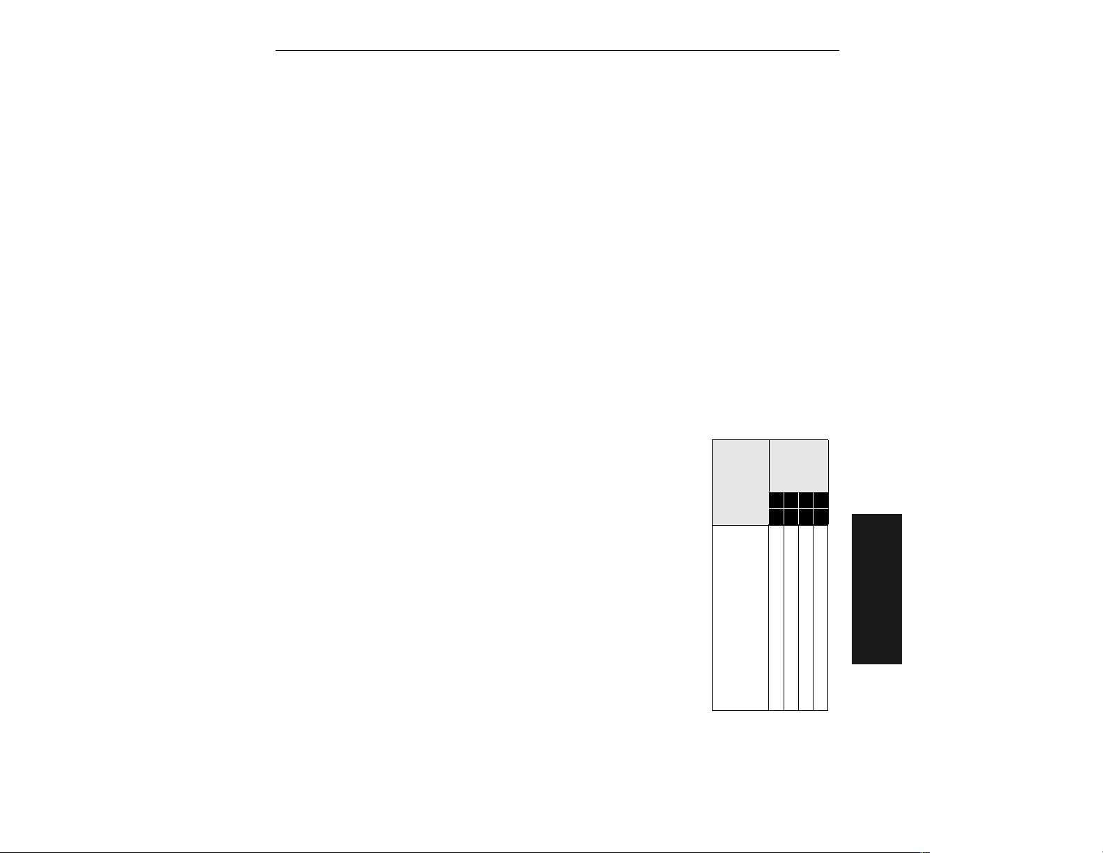
Checksum
Checksum
Part Number
Displays software part number.
Associated serial command: <#>
Checksum
Displays a four-digit hex number (corresponding to a given firmware version) used to
verify a scanner’s EPROM.
Associated serial command: <!>
Show Scanner Status
Used to display certain operating parameters (NOVRAM, command, and operation status). After sending this command, the
scanner immediately responds with <X>, where “X” is an
∆
ASCII character between @ and
on the ASCII table.
Associated serial command: <?>
To interpret the scanner’s status,
1. Look up the ASCII character’s Hex value in the ASCII table on
page A-10.
For example, the scanner responds with an <M>, corresponding Hex value is 4D.
2. Refer to table 4-3 to find the Hex value’s binary conversion.
The binary bit digits for “4” equal 0100; the binary bit digits for
“D” equal 1101. Hence, the binary conversion of 4D is
01001101.
Table 4-3 Hex
Value to Binary
Conversion
Binary
Hex
Value
Digits
0
1
2
3
4
5
6
7
8
9
A
B
C
D
E
F
Bit
Digits
7 6 5 4
3 2 1 0
0
0
0
0
0
0
1
0
0
1
0
0
0
1
0
0
1
0
1
1
0
1
1
0
0
0
1
0
0
1
1
0
1
1
0
1
0
1
1
0
1
1
1
1
1
1
1
1
0
1
0
1
0
1
0
1
0
1
0
1
0
1
0
1
4–Utilities
MS-810 Industrial Scanner User’s Manual
4-13
Page 96
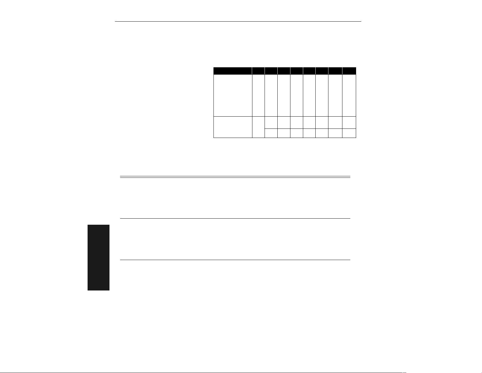
Chapter 4
In the example shown in table
4-4, a scanner status request
returns an <M>
corresponding to 4D hex or
01001101. This means that
in table 4-4 (each bit has a specific meaning)
Table 4-4 Finding Scanner Status from Binary Bit Digits
Binary Code
Bit Location: 7 6 5 4 3 2 1 0
0100110 1
the scanner’s status is even
parity, (skip bit location 6; it
3.Compare bit digits with the “Is Status Active?” row
will always equal 1), with the
scanner not in a read cycle,
with the motor spinning and
Scanner
Status:
a
the scanner ready to read,
Parity
Always set to 1
Scanner is in
a read cycle
Motor is spinning;
scanner is ready
NOVRAM error
detector
Communication
error detected
Command
received
Command
with no NOVRAM error
detected, with a
communications error
detected, with the command
Is Status
Active?
not received, and with a
If you send
<?>
the
After Power-on
(NOVRAM
Read)
After Sending
a Command
After NOVRAM
4–Utilities
Write
The scanner
will report:
Whether the
NOVRAM was
read correctly the
first time the
status command
was received.
Whether the
command was
sent correctly.
Whether the
NOVRAM was
written correctly.
For example:
With the scanner in a triggered mode without a serial or
edge trigger present, power–off, then power–on and enter
the
<?>
a good load or
detected” in table 4-4 on page 4-14.
With the scanner in a triggered mode without a serial or edge
trigger present, enter the
flags. Then enter the desired command,
Enter
command was received,
command, or
The scanner responds in the same manner as after power–
on (NOVRAM read).
Yes =
No =
NOVRAM status is valid only after the first status request
a.
following a NOVRAM read or write.
command. The scanner responds with <@> for
<H>
<?>
again. The scanner responds with <B> if the
<F>
N/A10011 1
N/A01100 0
1 = odd
0 = even
for a bad load. See “NOVRAM error
<?>
command to clear the error
<L1>
for example.
<C>
if there was an error in the
if there was a serial data error.
error detected
Show Software Status
Sends the following in this order: status byte, part number, ROM checksum for both
possible lengths of ROM (1 megabyte and 512 bytes), current NOVRAM checksum, and
NOVRAM checksum at power up.
Associated serial command: <?1>
4-14
MS-810 Industrial Scanner User’s Manual
Page 97

Code Type Commands
Code Type Commands
(Not in the Utilities Menus.)
Autodiscriminate All Codes
Enables the scanner to decode all available bar code types without changing scanner
configuration settings.
: For maximum scanning speed, enable only those bar code symbologies used in
Note
the application.
Associated serial command: <P>
Code 39 Only
Allows only Code 39 labels to be read.
Associated serial command: <Q>
Codabar Only
Allows only Codabar labels to be read.
Associated serial command: <R>
I 2 of 5 Only
Allows only Interleaved 2 of 5 labels to be read.
Associated serial command: <S>
MS-810 Industrial Scanner User’s Manual
4–Utilities
4-15
Page 98

Chapter 4
4–Utilities
4-16
MS-810 Industrial Scanner User’s Manual
Page 99

Appendices
Contents
Appendix A — Scanner Specifications ............................................... A-2
Appendix B — Electrical Specifications .............................................. A-4
Appendix C — Ground and Shield Considerations ..................................A-9
Appendix D — ASCII Table .............................................................. A-10
Appendix E — Transferring/Restoring Files ..................................... A-11
Appendix F — IB-130 Interface Module ........................................... A-13
Appendix G — Number of Scans ..................................................... A-18
Appendix H — Special 5 VDC MS-810 ............................................ A-21
Appendix I — Using the IB-105 ........................................................ A-22
Appendix J — Troubleshooting ........................................................ A-28
Appendix K — Bar Code Symbology ............................................... A-31
Appendix L — Interface Standards .................................................. A-32
Appendix M — Multidrop Communications ............................................A-33
Appendix N — Glossary of Terms .................................................... A-36
MS-810 Industrial Scanner User’s Manual
Appendices
A-1
Page 100
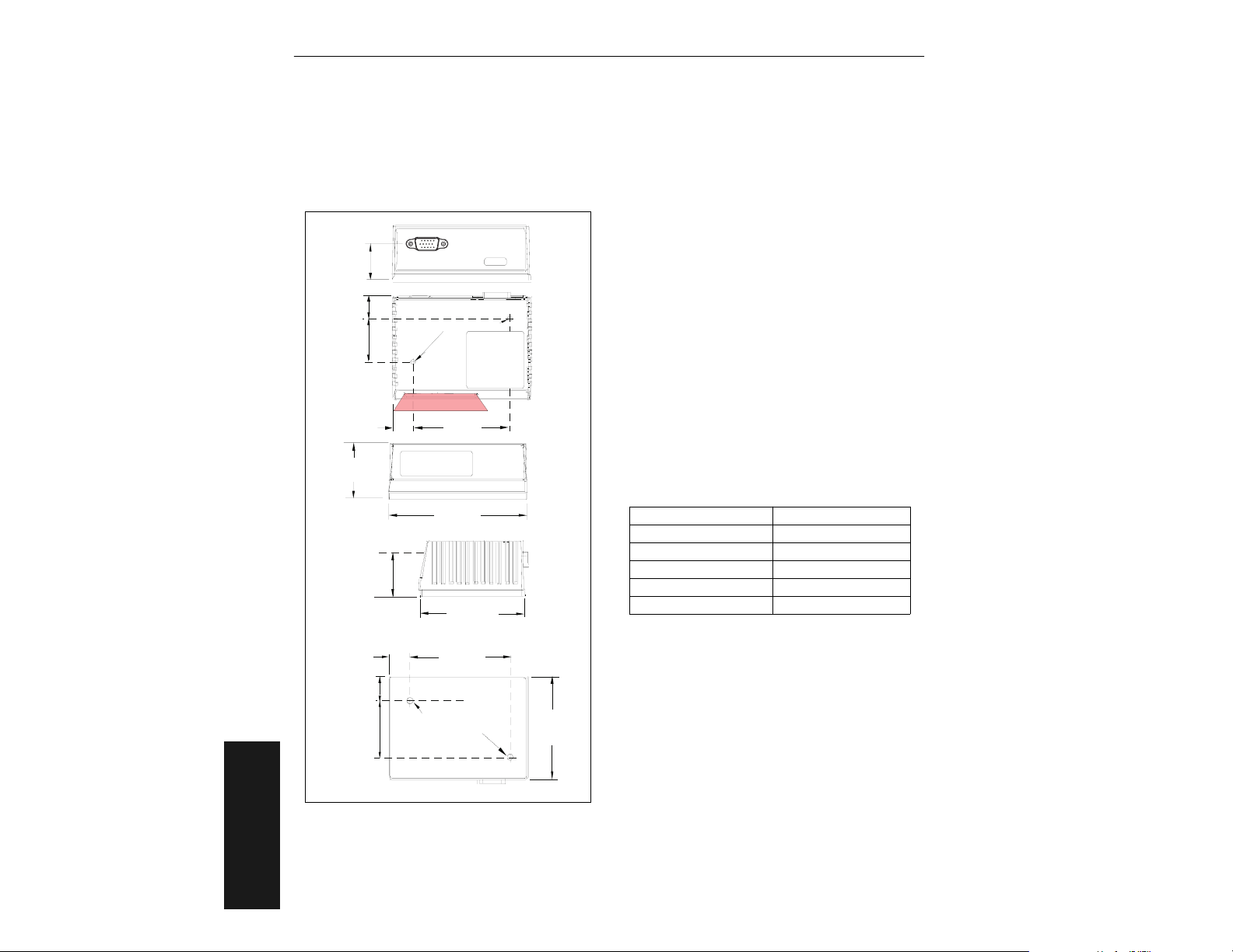
Appendix A — Scanner Specifications
Mechanical Parameters
Length: 3.47” (8.81 cm)Width: 2.59” (6.58 cm)
Height: 1.38” (3.50 cm)Weight: 7.5 oz. (212 g)
2.40"
(6.10 cm)
Front
3.47"
(8.81 cm)
(6.58 cm)
2.50"
(6.35 cm)
Bottom
2.59"
Back
Top
2.59"
(6.58 cm)
.93"
(2.36 cm)
.54"
(1.37 cm)
1,10"
(2.79 cm)
(1.35 cm)
1.38"
(3.50 cm)
(1.57 cm)
(3.56 cm)
.53"
1.10"
(2.7 cm)
.62"
1.40"
M4 x 0.7 x 4.57 mm deep
Mounting holes
(2 places)
Side
.54"
(1.37cm)
M4 x 0.7 x 3.8 mm deep
Mounting holes
(2 places)
Figure A-1 MS-810 Dimensions
Light Source
Type: Laser Diode
Output
Wavelength: 670 nm nominal
Safety Class: CDRH Class II
Operating Life: 50,000 hours @25°C
(10,000 hours @50°C)
Laser Cooling: Thermostatically-controlled thermo-
cooler
Scanning Parameters
Primary Mirror Type: Rotating, 10-faceted
Scan Rate: 300 to 800 scans per second;
default is 400.
Scan Width Angle: Typically 60°
Pitch: ±50° maximum
Skew: ±40° maximum
Label Contrast: 25% min. absolute dark to light
differential at 670 nm wavelength
Optional Raster Mirror Image: 10 raster scan lines
over a 2-degree arc
Scan Range Raster Height
2 inches (50.8 mm) 0.10 inch (2.54 mm)
4 inches (101.6 mm) 0.17 inch (4.32 mm)
6 inches (152.4 mm) 0.24 inch (6.1 mm)
8 inches (203.2 mm) 0.31 inch (7.87 mm)
10 inches (254 mm) 0.38 inch (9.65 mm)
Communications
Interface: RS-232 standard; also available:
RS-422/485, *DeviceNet, *SDS, *Profibus DP,
*Ethernet
Baud Rates: 300, 600, 1200, 2400, 4800, 9600,
19.2K, 38.4K, 76.8K
Parity: Odd, Even, None
Stop Bits: 1, 2Data Bits: 7, 8
Protocols
Point-to-Point, Point-to-Point w/RTS/CTS, Point-toPoint w/XON/XOFF, Point-to-Point w/RTS/CTS &
XON/XOFF, Polling Mode D, Multidrop, User Defined,
User Defined Multidrop.
Appendices
A-2
MS-810 Industrial Scanner User’s Manual
 Loading...