

Micropump GN Series Series Installation
1
DOC No: 7046 REV G
INSTALLATION, OPERATION AND WARRANTY INFORMATION
2
PUBLISHED BY
MICROPUMP INC.
A Unit of IDEX Corporation
March 2006 © Micropump Inc.
All rights reserved.
This manual contains proprietary information which is protected by copyright.
No part of this publication may be reproduced, transcribed, stored in a
retrieval system, translated into any language (including computer language),
or transmitted in any form without the written consent of the publisher. For
further information contact your local Micropump distributor. Every effort
has been made to ensure that the information contained in this manual is
accurate prior to printing. However, the products described in this manual are
subject to continuous development and improvement and Micropump shall
not be liable for any errors contained herein or for incidental or consequential
damages in connection with the furnishing, performance, or use of this
manual.
EC DECLARATION OF INCORPORATION
EC DECLARATION OF CONFORMITY
Herewith we declare that the products described in this Installation,
Operation, and Warranty Handbook complies with the following provisions
applying to it:
Machinery Directive 2006/42/EC. Applied harmonized standards,
in particular:
EN 809:1998
ISO12100-1:2003 (replacing EN292-1:1991)
ISO12100-2:2003 (replacing EN292-2:1991)
EN14121-1:2007
ISO14847:1999
EN12162:2001
EN ISO 20361:2009
EN ISO 13732-1:2006
Manufacturer: Importer in country of use:
Micropump Vancouver
1402 NE 136
Vancouver, WA 98684
th
Avenue
(Signature of Manufacturer)
The machinery described in this certificate must not be put into service until the machinery in which it is
incorporated has been declared in conformity with the provisions of the Machinery Directive and their
amendments.
DOC No: 7046 REV G
(Signature of Importer)

3
DOC No: 7046 REV G
STANDARD LIMITED WARRANTY
The products manufactured by Micropump Incorporated are warranted to be
free from defects in workmanship and material at the time of shipment from the
place of manufacture. Micropump will repair or replace, at its option, any part
or component which fails to conform to this warranty for a period of one year.
Micropump’s obligation under this warranty is limited to the repairs or replacement
of defective equipment returned to Micropump on an F.O.B. destination and
freight-prepaid basis. All normal wear and tear is excepted, and product is
subject to examination at Micropump to verify that the parts or components were
defective at the time of sale.
No warranty of any kind is made or shall be imposed with respect to any pump
or parts (1) that have not been properly installed and tested in operation, (2)
that have been subject to misuse, negligence, acts of God or the elements, or
any other form of casualty, or (3) that have been repaired or altered outside
Micropump’s facility in a way, so as, in our judgment, to affect performance or
reliability.
The parties agree that the buyer’s sole and exclusive remedy against Micropump
shall be for repair or replacement of defective parts under the conditions stated
above. The buyer agrees that no other remedy (including but not limited to
incidental or consequential damages for lost profits, lost sales, loss of use, injury
to person or property, or any other incidental or consequential loss) shall be
available to them.
This warranty shall not apply to prototype pumps, experimental pumps, or brushtype electric motors. Warranty of equipment or accessories from outside sources,
purchased by Micropump and incorporated into Micropump’s product is subject
to the manufacturer’s standard warranty, unless specifically agreed otherwise
between Micropump and buyer. A copy of the warranty on the aforementioned
equipment is available on request.
The adjustment or replacement of defective parts made under this warranty will
not extend the original warranty period.
THE WARRANTY DESCRIBED ABOVE IS THE EXCLUSIVE
MICROPUMP WARRANTY AND IS IN LIEU OF ALL OTHER
WARRANTIES, EXPRESSED OR IMPLIED, INCLUDING ANY
WARRANTY OF MERCHANTABILITY OR FITNESS FOR A
PARTICULAR PURPOSE OR ANY WARRANTY PREVIOUSLY ISSUED.
WE NEITHER ASSUME NOR AUTHORIZE ANY PERSON TO ASSUME
FOR US ANY OTHER LIABILITY IN CONNECTION WITH THE SALE
OR USE OF OUR EQUIPMENT.

4
DOC No: 7046 REV G
Your Micropump Product...
represents years of fluid handling experience and we feel it is the finest product
available of its type.
The product you have purchased was designed and constructed to handle compatible,
clean fluids within designated limits and conditions. Staying within performance limits
and following the guidelines given in this manual will result in excellent performance
and maximum pump life.
Should you have a question or a problem, technical assistance is available worldwide.
Micropump products are designed for easy field servicing with service kits and technical
support available for all products.
The Purpose of this Guide...
is to provide information to enable suitably qualified technicians and fitters to install,
operate and maintain Micropump pumps.
Use this Guide...
when you have purchased a pump, adaptor, or assembly including these components.
This guide contains specific information for installation, operation, and maintenance
of Micropump pumps. General information is given on installation within a system, but
reference should always be made to instructions provided with ancillary equipment
when installing the unit.
Abbreviations
The following abbreviations are used in this guide:
PEEK - Polyetheretherketone PPS - Polyphenylenesulfide
PTFE - Polytetrafluoroethylene NPSH - Net Positive Suction Head
NPT - American National Standard
Taper Pipe Thread
O/C
Pump
Type
Series
Modifier
Design
Modifier
Gear
Set
. Gear
Material
Seal
Material
Base
Material
. Drive
Mount
Base Code:
Bypass Driven
Magnet
Driving
Magnet
High System
Pressure
Bushing
Material
Shaft
Material
Port
Fittings
Port
Orientation
Gear
Trim
Other
Options Code:
Product Labeling
Micropump products are labeled with a product code. The code describes the pump
configuration and materials of construction. The first eight positions of the code
describe the base configuration. The remaining ten positions in the code describe the
optional features. Options that are not used are not shown in the code. For pumps
equipped with adapter and/or motor the product code is truncated at the design
modifier, later positions then describe the adapter and/or motor. Your Micropump
distributor can provide additional information about the product code.
Safety
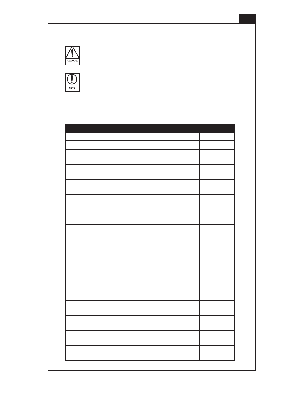
CAUTION
NOTE
Warning - Hot Surface is used to alert the reader to a procedure or
practice, which if not followed correctly, could result in personal injury
due to contact with a hot surface.
Cautions are used to alert the reader to a procedure or practice, which
if not followed correctly, could result in damage to the pump, motor, or
ancillary equipment.
Notes are used to highlight important information that may assist the reader in
carrying out a procedure or in understanding the text.
The following are used throughout this guide to indicate procedure that, if not followed
correctly, may result in injury to personnel or damage to equipment.
Warnings are used to alert the reader to a procedure or practice, which if
not followed correctly, could result in personal injury.
5
Table of Contents
Limits of Use 6
Installation in Explosive and Fire Danger Zones 7
Description 8
Motor Adaptors 9
Unpacking and Storage 9
Assembly 10
Space Requirements 10
Location 10
Filtration 11
Fittings 12
Piping 13
Mounting 13
Electrical Connection 14
Air Connection 14
Operation 15
Bypass Option 16
Magnet Decoupling 17
Maintenance 18
Fault Isolation 19
Technical Specification 20-34
DOC No: 7046 REV G
6
CAUTION
CAUTION
CAUTION
CAUTION
Corrosive Liquids. Corrosive liquids may eventually produce leak paths
around the sealing surfaces of the pump. The product and system piping
should be inspected for leaks on a regular basis.
Flooding and Water Immersion. The products covered by this guide are
not designed to operate immersed in water. Reference should always be
made to the installation and operating instructions for the motor under
such conditions.
Condensation. When pumping cold liquids ensure that condensation
does not present a safety hazard. Condensation on the external surfaces
of the magnet cup may result in motor seizure. Reference should always
be made to the installation and operating instructions for the motor
under such conditions.
Mechanical Danger. The product must be installed in a location that
exposes it to a low risk of external damage.
High Pressure Fluid Ejection. When operated within its technical
specification the product’s seals will prevent high pressure fluid
ejection. The system should include a pressure relief valve if the pump
is capable of exceeding the maximum system pressure.
Flammable Liquids. The fluids to be pumped should be maintained
below flash point temperature and there should be no possibility of
explosive vapors being within the product.
Hot Surfaces. Under some operating conditions, surface temperatures
can exceed 90°C (195°F.) Do not touch products while operating. Do not
touch within 30 minutes of system shutdown to allow surfaces to reach
safe handling temperature.
Limits of Use
To achieve optimum performance and safe operation Micropump
products must be operated with the limits given in the Technical
Specification. Operation outside these limits is not recommended and
may result in damage to the product and/or ancillary equipment.
Temperature. Operating beyond the maximum operating temperature
given in the technical specification is not recommended and may result
in damage to the product or compromise safety by creating high surface
temperature.
Excessive wear. Wear resulting from driven magnet rub on the magnet
cup can generate high external surface temperatures or degrade the
capability of the pressure boundary. Remove the product from service
and replace or repair if performance degrades significantly or becomes
noisy.
Freezing. Fluid must not be allowed to freeze inside the product.
DOC No: 7046 REV G
7
Leaking fluids may cause an unsafe condition. The product and system
piping should be inspected for leaks on a regular basis.
Installation in Explosive and Fire Danger Zones
Micropump offers products designed and tested for installation in explosive or fire
danger zones. Contact your local Micropump distributor or contact Micropump directly
to determine if your product combination can be certified for this use.
In Addition to the warnings provided throughout this manual, the following must be
considered in any explosion or fire danger zone installation:
Ensure the pump head, motor, and any mounting adapter are suitable for
area classification.
Ensure that pumping liquid temperature is maintained within acceptable
range as specified by Micropump Certification of ATEX Conformity.
Neodymium Iron Boron hub magnets (Driving Magnet product codes N3
and N4) cannot be certified for use in potentially explosive atmospheres.
DOC No: 7046 REV G

8
Description
Cavity Style Gear Pumps - Series GAT, GD, GJ, GK, GL, GM, GN
Cavity-style gear pumps are rotating positive displacement pumps. The main pump
components are fabricated of a variety of machined metal components, the gears and
bushings are molded or machined from plastics, and a variety of perfluoromers and
elastomers are used for the static seals. There are no dynamic seals. These pumps
are magnetically coupled to their drive. The driven magnet is fixed to the driving gear
shaft . Rotation of the hub magnet by the drive causes the driven magnet and driving
gear to rotate synchronously. The magnet cup provides a pressure boundary between
the pumped fluid and the surrounding environment. Fluid enters the inlet port and is
swept by the gears around the cavity to the outlet port. Pressure is developed in the
pump by restrictions on the outlet, which load the gears against the cavity and the
shafts against the bushings. In most cases, the pumped fluid provides the cooling
and lubrication for the bushings. Some pumps are fitted with an internal bypass. By
setting the spring tension in the bypass assembly, the discharge pressure can raise the
bypass poppet recirculating fluid to the inlet side of the pump. Pumps without bypasses
can be operated in reverse direction with degradation in performance and reduction in
life. Contact your local Micropump distributor or contact Micropump directly for pumps
designed to operated continuously in reverse direction.
Suction Shoe Gear Pumps - Series GA, GAH, GAP, GB, GC
Suction shoe gear pumps are rotating positive displacement pumps. The main pump
components are fabricated of a variety of machined metal components, the gears and
suction shoes are molded or machined from plastics, and a variety of perfluoromers and
elastomers are used for the static seals. There are no dynamic seals. These pumps
are magnetically coupled to their drive. The driven magnet is fixed to the driving gear.
Rotation of the hub magnet by the drive causes the driven magnet and driving gear to
rotate synchronously around a non-rotating shaft. The magnet cup provides a pressure
boundary between the pumped fluid and the surrounding environment. Fluid enters
the inlet port and is swept by the gears around the cavity to the outlet port. Pressure is
developed in the pump by restrictions on the outlet, which load the gears against the
suction shoe and shafts. In most cases, the pumped fluid provides the cooling and
lubrication for the bearing area. Initial start up of the pump is facilitated by a spring
or ball that holds the suction shoe in place until differential pressure across the shoe
dominates the load on the shoe. Some pumps are fitted with an internal bypass. By
setting the spring tension in the bypass assembly, the discharge pressure can raise the
bypass poppet recirculating fluid to the inlet side of the pump.
Centrifugal Pump – Series CA
The Series CA are centrifugal pumps fabricated of 316 Stainless Steel or Hastelloy C.
Bearings are Teflon, PPS or PEEK. Static seals are Teflon or Viton.
Centrifugal pumps are rotating, dynamic pumps. The pump is magnetically coupled
to its driver. The driven magnet is fixed to the impeller. Rotation of the hub magnet
by the drive causes the driven magnet and impeller to rotate synchronously around a
non-rotating shaft. Fluid enters the axially located inlet port and is accelerated by the
impeller to the tangentially located outlet port.
Pressure is developed in the pump by restrictions on the outlet, which causes the
impeller to load against the thrust plate. The magnet cup, formed from 316 SS
or Hastelloy C, provides a pressure boundary between the pumped fluid and the
surrounding environment.
DOC No: 7046 REV G
Description (continued)
Unpacking and Storage
If you have purchased a pump/motor combination this will be assembled ready
for installation. If you have purchased a pump without a motor you may require a
Micropump, NEMA, or IEC/ISO adaptor. If you have purchased an adaptor ensure you
have suitable pump or motor for your system. Contact your local Micropump distributor
or contact Micropump directly for assistance in selecting compatible components.
Use of non-Micropump adaptors may adversely affect your product
performance, installation category, and warranty. Contact your local
Micropump distributor or contact Micropump directly for information.
Motor Adaptors
Mounting screws are provided with Micropump supplied motors and adaptors.
Mounting screws are not provided with pumps or adapters.
NOTE
CAUTION
Piston Pumps - Series PD, PF
The Series PD and PF pumps are reciprocating piston pumps. The Series PD pumps
use a pair of pistons and a rotating valve to positively displace fluid. The Series PF
uses a single reciprocating and rotating piston without valves to positively displace
fluid. The main pump components are fabricated from a variety of machined metal
and ceramic pistons, molded and machined plastics and elastomer seals. Piston
seals are dynamic and other seals are static. Pumps are directly coupled to drive
units. The series PD drive rotates a swash plate that axially displaces the pistons. The
series PF drive rotates an angled piston, generating a combined axial and rotational
displacement. With the outlet port closed, fluid enters the inlet port as the piston
is withdrawn. With the inlet port closed, fluid exits the outlet port as the piston is
extended. Pressure is developed by restrictions in the outlet, causing the pistons to
load against the swash plate (Series PD) or the drive shaft and pump body (Series PF).
9
Inspect the magnet cup, hub, or adaptor (if present) before assembly
with the motor. Replace or repair if there are signs of damage.
Before installing the product ensure all transit packaging has been removed.
Remove the blanks from the pump inlet and outlet ports. If the pump is to be stored
prior to installation, re-pack the pump in its original packing, refit the blanks to the ports
and store in a dry, covered environment.
Protect the pump head, hub, or adaptor from damage during unpacking and installation.
Impacts to the magnet cup can cause internal damage or result in rub between the
magnet cup and driving magnet upon assembly with the motor. Damage to the hub or
adaptor may result in rub between the magnet cup and driving magnet upon assembly
with the motor.
DOC No: 7046 REV G
10
The foundation must be capable of supporting the combined weight of
the pump and motor and provide a rigid support.
If the pump head housing assembly and motor are supplied separately they will need
to be assembled prior to the installation. Align the housing flange so that it fits into the
matching recessed flange on the motor assembly and tighten screws evenly. Align the
pump head components with the housing flange and secure with the supplied screws.
Tighten screws evenly and in an alternating pattern. Refer to the service instruction
sheet for the specific pump model being used for proper torque values.
Assembly
Proper assembly is required to prevent magnet rub due to misalignment.
Loose pump head or adaptor bolts may cause misalignment which
may result in magnet hub rub on the magnet cup causing high surface
temperatures or weakening the pressure boundary created by the
magnet cup.
Space Requirements
Refer to the Technical Specification for overall dimensions and weights of the pumps
covered by this guide.
Location
Pumphead or adaptor cannot support the weight of the motor. Ensure
the motor is adequately supported by the foundation and/or mounting
bracket.
The pump should be located with the inlet below or even with the liquid level of the
fluid supply. The pump can be mounted in any position. Ensure that there is adequate
space for operation, inspection and maintenance.
DOC No: 7046 REV G
11
CAUTION
Filtration
The pump can be damaged if the fluid being pumped has abrasive
suspended solids. Always install a suitable filter or strainer when these
fluids are being pumped.
All strainers and filters should have large surface areas to prevent excessive
pressure drop.
For open systems the filter must be installed on the inlet side of the pump. For closed
loop systems the filter can be installed on the inlet or discharge side.
Ensure filters are of the correct size for the pump being installed, refer to the table
below for correct sizing:
RECOMMENDED FILTER
Model Size Type Max Pressure Drop
SERIES CA 50 micron MESH
SERIES GA 5 micron FINE MESH OR
CANISTER
SERIES GAH 5 micron FINE MESH OR
CANISTER
SERIES GAP 5 micron FINE MESH OR
CANISTER
SERIES GAT 5 micron FINE MESH OR
CANISTER
SERIES GB 40 micron SOFT PARTICLE
CANISTER 0.27 bar (4 psi)
5 micron HARD PARTICLE
SERIES GC 40 micron SOFT PARTICLE
CANISTER 0.27 bar (4 psi)
5 micron HARD PARTICLE
SERIES GD 40 micron SOFT PARTICLE
CANISTER 0.27 bar (4 psi)
5 micron HARD PARTICLE
SERIES GJ 40 micron SOFT PARTICLE
CANISTER 0.27 bar (4 psi)
5 micron HARD PARTICLE
SERIES GK 40 micron SOFT PARTICLE
CANISTER 0.27 bar (4 psi)
5 micron HARD PARTICLE
SERIES GL 40 micron SOFT PARTICLE
CANISTER 0.27 bar (4 psi)
5 micron HARD PARTICLE
0.14 bar (2 psi)
0.14 bar (2 psi)
0.14 bar (2 psi)
0.14 bar (2 psi)
SERIES GM 40 micron SOFT PARTICLE
CANISTER 0.27 bar (4 psi)
5 micron HARD PARTICLE
SERIES GN 40 micron SOFT PARTICLE
CANISTER 0.27 bar (4 psi)
5 micron HARD PARTICLE
SERIES PD 5 micron FINE MESH OR
CANISTER
SERIES PF 5 micron FINE MESH OR
CANISTER
0.14 bar (2 psi)
0.14 bar (2 psi)
DOC No: 7046 REV G
 Loading...