

Page 1
SERVICE INSTRUCTIONS: L23154
MODEL: 5500/56C
PART NUMBER:
REVISION
LTR. DESCRIPTION DATE BY
A ORIGINATED PER E14164 1/28/04 CMA
L23154
1. Description and Operation
1.1 The Model 5500 pump is a positive displacement gear pump constructed of 316 stainless steel, PEEK
or Teflon, and Viton.
Special pumps may be constructed of alternate materials. The pump is magnetically driven and is therefore
leak-proof and contamination free. The pump is self priming under normal conditions.
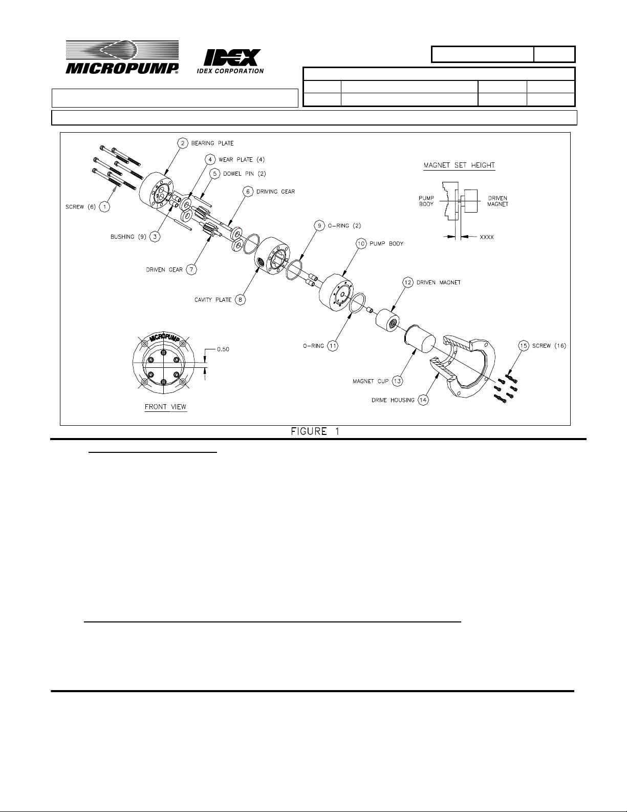
1.2 Drive power for the pump is provided by the motor via the magnetic coupling. An exploded view is
shown in Figure 1. Fluid is drawn into the pump due to the negative pressure created by the gear
rotation in the cavity plate. The fluid is contained by the gear teeth, cavity walls, and gear mesh to
create fluid transfer and pressure.
2. Tools and materials required for Disassembly, Repair, and Assembly of Pump
2.1 Hex Keys (9/64”, 3/16”, and 5/16”)
2.2 X-Acto knife (or equivalent)
2.3 Masking Tape
MICROPUMP, INC.
A Unit of IDEX Corporation
PO Box 8975, Vancouver, WA 98668-8975 • Phone: 360/253-2008 • Fax: 360/253-8294
Howard Road, Eaton Socon, St.
MICROPUMP
A Subsidiary of Micropump, Inc.
Neots, Cambridgeshire, PE 19 8ET England, • Phone: (44) (0) 1480-356600• Fax: (44) (0) 1480-35630
Page 1 of 9
LIMITED
0
Page 2
PART NUMBER:
L23154
2.4 Surface plate or equivalent flat
surface
2.5 Bushing insertion tool (or arbor press)
2.6 Reamer for bushings
2.7 Silicone vacuum Grease
2.8 Stoddard Solvent or liquid detergent
3. Disassembly of Pump (Refer to Figure 1)
Note: Prepare a clean, flat area, free of metal particles.
3.1 Place pumphead on surface with housing facing up.
NOTE: EXERCISE CAUTION IN THE FOLLOWING STEP.
ENTRAPPED FLUID WILL BE RELEASED WHEN PUMP BODY
AND MAGNET CUP ARE SEPARATED.
3.2 Remove the screws (15), qty 16 (Qty 8 for low pressure version), and pull the drive housing (14) and
magnet cup (13) from the pump body (10).
3.3 Separate magnet cup (13) and drive housing (14).
LTR. DESCRIPTION DATE BY
A ORIGINATED PER E14164 1/28/04 CMA
REVISION
3.4 Loosen the setscrew on the driven magnet (12) and remove magnet from
driving gear (6) shaft.
Note: Store the driven magnet (12) in a clean bag and keep away
from other magnets and sensitive electronic equipment.
3.5 Remove screws (1), qty 6, and pull bearing plate (2), cavity plate (8), and
two of the dowel pins (5) straight away from pump body (10).
3.6 Separate bearing plate (2), cavity plate (8), and two dowel pins (5) from each other. Gently
lift the wear plates (4) (if used), qty 4, out of the cavity plate (8), taking care to pull them
straight out.
Note: If dowel pins are difficult to remove, protect pins with a soft
material (i.e. plastic or rubber) and remove them with pliers.
Replace pins if damaged.
3.7 Remove driving gear (6) and driven gear (7) from pump body (10).
3.8 See repair instructions, section 6.5.1 regarding bushing (3), qty 9, removal.
MICROPUMP, INC.
A Unit of IDEX Corporation
PO Box 8975, Vancouver, WA 98668-8975 • Phone: 360/253-2008 • Fax: 360/253-8294
Howard Road, Eaton Socon, St.
MICROPUMP
A Subsidiary of Micropump, Inc.
Neots, Cambridgeshire, PE 19 8ET England, • Phone: (44) (0) 1480-356600• Fax: (44) (0) 1480-35630
Page 2 of 9
LIMITED
0
Page 3

PART NUMBER:
L23154
LTR. DESCRIPTION DATE BY
A ORIGINATED PER E14164 1/28/04 CMA
REVISION
Note: Remove bushings and O-
rings ONLY if replacement is necessary.
4. Inspection of Pump Components
4.1 Magnet Cup (10)
4.1.1 Visually check the outside of the magnet cup (13) for rub marks on the
back and sides. Marks on the back indicate that the hub assembly is
misaligned axially. Marks on the sides indicate radial misalignment.
4.1.2 Visually check the inside surfaces of the magnet cup (13) for rub marks. Marks on
the bottom surface indicate that either the driven magnet (12) or hub assembly is
misaligned. See section 7.12 for driven magnet (12) installation. See section
8.1 for hub assembly installation. Marks on the insides of the magnet cup (13)
indicate radial misalignment of the driven magnet (12), refer to section 6.2.
4.2 Driven Magnet (12)
4.2.1 Visually check the driven magnet (12) for wear on the outside shell; refer to section
6.2.
4.2.2 Visually check the driven magnet (12) for metal particles. See cleaning instructions,
section 5.
4.3 Driving gear (6) and driven gear (7)
4.3.1 Visually check the gear teeth on both gears for pits, wear, or damage.
Replace both gears if either gear is damaged or worn.
4.3.2 Visually check gear shafts for wear, pits, scoring, or corrosion. Light wear marks on
shaft circumference will not normally impede the operation of the pump. Replace
both gears if either gear shafts are scored or damaged.
Note: ALWAYS replace all bushings if either gear shaft is worn or damaged.
4.4 Bearing plate (2) (Section 4.4.1 applies when wear plates not used)
4.4.1 Visually check the bearing plate (2) surface that contacts the gears for scoring. Refer
to section 6.4.
4.4.2 Visually check the bearing plate lube holes for debris. See cleaning instructions,
section 5.
PO Box 8975, Vancouver, WA 98668-8975 • Phone: 360/253-2008 • Fax: 360/253-8294
Howard Road, Eaton Socon, St.
MICROPUMP, INC.
A Unit of IDEX Corporation
MICROPUMP
A Subsidiary of Micropump, Inc.
Neots, Cambridgeshire, PE 19 8ET England, • Phone: (44) (0) 1480-356600• Fax: (44) (0) 1480-35630
Page 3 of 9
LIMITED
0
Page 4

PART NUMBER:
L23154
LTR. DESCRIPTION DATE BY
A ORIGINATED PER E14164 1/28/04 CMA
REVISION
4.4.3 Visually check o-ring (9) and replace if damaged. (Note: if the pump is fitted with
Teflon o-rings, they should be replaced each time the pump seal is broken.)
4.5 Wear Plates (4) (OPTIONAL - Used a majority of the time)
4.5.1 Visually check the wear plates (4), qty 4, surface which contacts the gears for
scoring. Refer to section 6.4.
4.5.2 Visually check the wear plates (4), qty 4. See cleaning instructions, section 5.
4.6 Cavity Plate (8)
4.6.1 Visually check the cavity plate (8) for scoring in the gear cavity bores.
Refer to section 6.3.
4.6.2 Visually check o-ring (9) and replace if damaged. (Note: If the pump is fitted with
Teflon o-rings, they should be replaced each time the pump seal is broken.)
4.7 Pump Body (10) (Section 4.7.1 applies when wear plates not used)
4.7.1 Visually check the pump body (10) surface that contacts the gears for scoring. Refer
to section 6.4.
4.7.2 Visually check o-ring (11) and replace if damaged. (Note: If the pump is fitted
with Teflon o-rings, they should be replaced each time the pump seal is broken.)
5 Cleaning of Pump Assembly
5.1 Cleaning agents and materials
5.1.1 Use either a stoddard solvent or a mild solution of soap and water to clean the parts.
Masking tape will also be required.
5.2 Cleaning Procedures
5.2.1 Clean all metal and plastic parts with the solvent or soap solution. Rinse thoroughly
and allow to dry, or blow dry with clean, dry, compressed air.
CAUTION: DO NOT USE DETERGENT SOLUTION OR
SOLVENT ON ELECTRICAL PARTS OR MOTOR BEARINGS.
PO Box 8975, Vancouver, WA 98668-8975 • Phone: 360/253-2008 • Fax: 360/253-8294
Howard Road, Eaton Socon, St.
MICROPUMP, INC.
A Unit of IDEX Corporation
MICROPUMP
A Subsidiary of Micropump, Inc.
Neots, Cambridgeshire, PE 19 8ET England, • Phone: (44) (0) 1480-356600• Fax: (44) (0) 1480-35630
Page 4 of 9
LIMITED
0
Page 5

PART NUMBER:
L23154
LTR. DESCRIPTION DATE BY
A ORIGINATED PER E14164 1/28/04 CMA
REVISION
5.2.2 Remove all metal particles from the driven magnet (12) and hub assembly by
pressing adhesive side of masking tape against particles and removing tape.
Note: Loose iron particles and metal filings will be attracted to the magnet
surface and must be forcibly removed to prevent introducing rust into the system.
6 Repair of Pump Assembly
Note: Repair of the pump assembly is primarily limited to replacing parts.
6.1 Replace any part which exhibits damage such as wear, cracks, breaks, and
excessive scoring. See section 6.4 below regarding scoring of the wear
plates (4) (or bearing plate (2) and pump body (10) if wear plates are not
used).
6.2 Replace bushings (3) to correct for side “rub” marks on inside of magnet
cup (13) and on side of driven magnet (12). See repair instructions,
section 6.5.
6.3 Replace cavity plate (8) if gear cavity bores indicate excessive wear or damage.
6.4 Scoring of wear plates (or bearing plate & pump body when wear
plates not used)
6.4.1 Score marks that are deeper than 0.010” (.26 mm) cannot be corrected by
the following procedure and require replacement of the parts.
Minor scoring in the area of gear contact may be corrected by lightly sanding with
#600 wet/dry sandpaper. Place dry sandpaper on the surface plate, or equivalent flat
surface. A table top is not flat enough ! Do not use creased sandpaper! Lightly sand
in a “figure 8” pattern, taking care to keep the part flat against the sandpaper. Avoid
rocking the part, or applying unequal pressure to the top of the part. Normally the
deepest score marks will be found within a 1” (25.4mm) diameter around the shaft
holes. Typically, scoring outside this area can be removed after 4-6 passes, and all
but the deepest marks will be removed after 25-30 passes. If after 30 passes the score
marks occupy more than 10% of the total area in contact with the gear, replace the
part. Do not attempt to sand out deep score marks. Clean thoroughly after sanding;
see cleaning instructions in section 5.2.
PO Box 8975, Vancouver, WA 98668-8975 • Phone: 360/253-2008 • Fax: 360/253-8294
Howard Road, Eaton Socon, St.
MICROPUMP, INC.
A Unit of IDEX Corporation
MICROPUMP
A Subsidiary of Micropump, Inc.
Neots, Cambridgeshire, PE 19 8ET England, • Phone: (44) (0) 1480-356600• Fax: (44) (0) 1480-35630
Page 5 of 9
LIMITED
0
Page 6
PART NUMBER:
L23154
6.5 Bushing Installation
LTR. DESCRIPTION DATE BY
A ORIGINATED PER E14164 1/28/04 CMA
REVISION
6.5.1 Remove all bushings (3) from bearing plate (2) and pump body (10) using
a tap and handle. Thread tap into bushing approximately ½” (12 mm) and pull
bushings out.
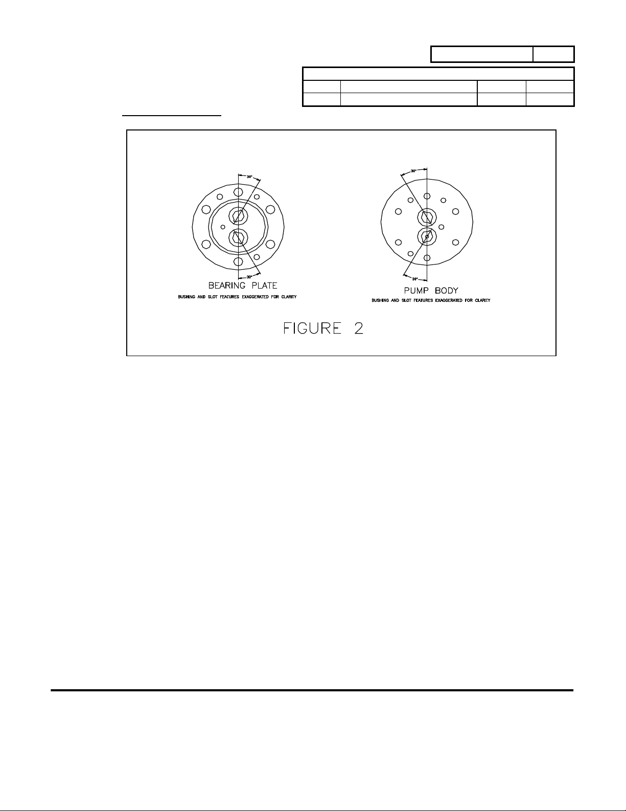
6.5.2 Install 4 bushings into bearing plate (2) 0.010” to 0.020” (0.26 mm to 0.51
below bearing plate sealing surface, with the slots (if present) aligned as shown in
figure 2. Use a bushing insertion tool and hand press or non-rotating drill press.
6.5.3 Install the first 4 bushings into pump body (10) 0.010” to 0.020” (0.26 mm
to 0.51 mm) below sealing surface of the “gear end” of the pump body. Align the
bushings slots as in figure 2. Install the remaining bushing into pump body from
driven magnet (12) end, aligning the slots as in figure 2, and the bushing flush with
the pump body surface.
6.5.4 Check all bushings for proper installation depth. Check bushings after
installation with a new gear shaft to insure that clearance between shafts
and bushings is at least a sliding fit.
6.5.5 If bushings are tight on shafts, very carefully hand ream bushings after
installation using a 0.251” (6.4 mm) diameter reamer. This should be
done as straight as possible to obtain maximum perpendicularity. Do not
force reamer into bushings, and do not ream bushings unless necessary.
PO Box 8975, Vancouver, WA 98668-8975 • Phone: 360/253-2008 • Fax: 360/253-8294
Howard Road, Eaton Socon, St.
MICROPUMP, INC.
A Unit of IDEX Corporation
MICROPUMP
A Subsidiary of Micropump, Inc.
Neots, Cambridgeshire, PE 19 8ET England, • Phone: (44) (0) 1480-356600• Fax: (44) (0) 1480-35630
Page 6 of 9
LIMITED
0
Page 7

PART NUMBER:
L23154
LTR. DESCRIPTION DATE BY
A ORIGINATED PER E14164 1/28/04 CMA
7 Pump assembly (Refer to Figure 1)
Caution: Do all work on a clean surface free of metal particles.
7.1 Install driving gear (6) into pump body (10) center hole with the long end
of the gear shaft placed in the hole. The shaft should slide and rotate freely in the bushings
(if not: see repair instructions, section 6.5.5.).
7.2 Install driven gear (7) into the remaining pump body (10) hole containing
bushings, with the long end of the gear shaft placed in the hole. The shaft should slide and
rotate freely in the bushings (if not: see repair instructions, section 6.5.5). Check that gears
rotate easily and mesh without sticking. Place the two wear plates (if used) over the gears,
orienting the flow holes as shown in the drawing.
7.3 Install 2 dowel pins (5) into pump body (10).
7.4 If elastomer o-rings are used, apply a light even film of Dow Corning
vacuum grease or equivalent (do not use on Teflon seals). Apply grease
from capsule to the thumb and index finger of one hand, and transfer a light even film to the
surface by rubbing o-ring between thumb and index finger. Check that entire surface of oring is coated with vacuum grease.
7.5 Install the 2 o-rings (9); one into the cavity plate (8) o-ring groove and
the other into the bearing plate (2) o-ring groove. Teflon o-rings may require slight
stretching in order to fit into the grooves.
7.6 Place the cavity plate (8) over the gears/wear plates (if used) and onto the
pump body (10) dowel pins. Press the cavity plate flush with the pump
body sealing surface.
7.7 Install 2 dowel pins (5) into cavity plate (8).
7.8 Place the bearing plate (2) over the gears/wear plates (if used) and onto the
cavity plate (8) dowel pins. Press the bearing plate flush with the cavity
plate sealing surface.
7.9 Install 6 screws (1) through the bearing plate (2) and into the pump body (10). Torque to 40
in-lbs. It is advised to apply a light oil to screw threads
and under screw head before installation.
REVISION
PO Box 8975, Vancouver, WA 98668-8975 • Phone: 360/253-2008 • Fax: 360/253-8294
Howard Road, Eaton Socon, St.
MICROPUMP, INC.
A Unit of IDEX Corporation
MICROPUMP
A Subsidiary of Micropump, Inc.
Neots, Cambridgeshire, PE 19 8ET England, • Phone: (44) (0) 1480-356600• Fax: (44) (0) 1480-35630
Page 7 of 9
LIMITED
0
Page 8

PART NUMBER:
L23154
LTR. DESCRIPTION DATE BY
A ORIGINATED PER E14164 1/28/04 CMA
REVISION
Note: Pumps with Teflon o-rings may require screws to be tightened 2 to 3
times, due to the hardness of the Teflon material.
7.10 If an elastomer o-ring is used, apply a light even film of Dow Corning
vacuum grease or equivalent (do not use on Teflon seals). Apply grease from capsule to
the thumb and index finger of one hand, and transfer a light even film to the surface by
rubbing o-ring between thumb and index finger. Check that entire surface of o-ring is
coated with vacuum grease.
7.11 Install one o-ring (11) into the pump body (10) o-ring groove. Teflon
o-rings may require slight stretching in order to fit into grooves.
7.12 Position driven magnet (12) on driving gear (6) shaft, aligning magnet set
screw with flat of shaft. Locate driven magnet at a set height of .375” (9.5
mm) as shown in Figure 1, and tighten set screw on flat of shaft.
7.13 Check that driven magnet (12) is free of metal particles (see cleaning
instructions, section 5). Check that driving gear (6) shaft rotates
without sticking (see repair instructions, section 6.5.5).
7.14 Install magnet cup (13) over driven magnet (12), onto o-ring (11) in pump
body.
7.15 Complete the pump assembly with 16 screws (15) (8 screws for low
pressure version) installed through the drive housing (14) and into the
pump body (10). Torque to 30-35 in-lbs It is advised to apply a light oil
to screw threads and under screw head before installation.
7.16 Check that all screws are seated. There should not be any gaps between
mating parts.
8 Pump to Motor Assembly
8.1 The hub assembly should be attached to the motor shaft using key and set
screw. The hub assembly is designed so that when placed on the motor
shaft it will automatically bottom out at the proper setting
8.2 Install pump assembly onto motor. Care should be taken to disallow the
hub assembly from impacting the magnet cup due to high magnetic
attraction.
PO Box 8975, Vancouver, WA 98668-8975 • Phone: 360/253-2008 • Fax: 360/253-8294
Howard Road, Eaton Socon, St.
MICROPUMP, INC.
A Unit of IDEX Corporation
MICROPUMP
A Subsidiary of Micropump, Inc.
Neots, Cambridgeshire, PE 19 8ET England, • Phone: (44) (0) 1480-356600• Fax: (44) (0) 1480-35630
Page 8 of 9
LIMITED
0
Page 9

PART NUMBER:
L23154
LTR. DESCRIPTION DATE BY
A ORIGINATED PER E14164 1/28/04 CMA
REVISION
8.3 Determine proper port location, and position pump assembly accordingly.
8.4 Install 4 bolts and torque to 20 in-lbs.
8.5 Test pump to applicable specifications for the pump/motor combination.
9 Storage
9.1 Prepare the pump for storage by installing plugs into the inlet and outlet ports.
Note: Tape can be used in lieu of plugs for sealing ports.
Remove as much fluid as possible from the pump prior to sealing ports.
9.2 Store the pump in any position in an ambient temperature-humidity environment.
Note: If water is left in the pump, damage may occur if the
temperature drops below freezing.
PO Box 8975, Vancouver, WA 98668-8975 • Phone: 360/253-2008 • Fax: 360/253-8294
Howard Road, Eaton Socon, St.
MICROPUMP, INC.
A Unit of IDEX Corporation
MICROPUMP
A Subsidiary of Micropump, Inc.
Neots, Cambridgeshire, PE 19 8ET England, • Phone: (44) (0) 1480-356600• Fax: (44) (0) 1480-35630
Page 9 of 9
LIMITED
0
 Loading...