

Micropump GL Series Service Instructions
SERVICE INSTRUCTIONS:
MOD: 5000
PART NUMBER:
REVISION
LTR. DESCRIPTION DATE BY
C REVISED PER ECN 4725 11-11-98 LFK
6779
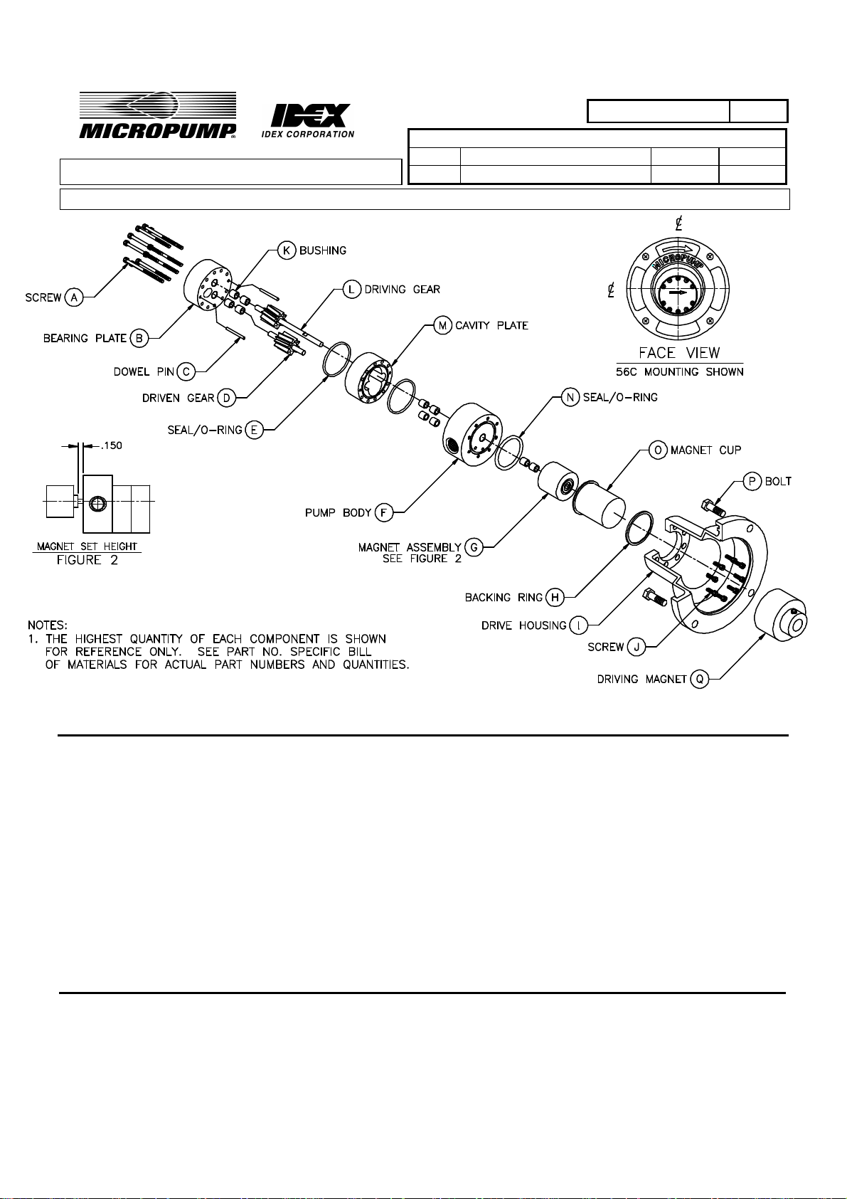
FIGURE 1
1. Description and Operation.
1.1 The Model 5000 pump is a positive displacement gear pump constructed of 316 stainless steel, Teflon,
PEEK and or Carbon.
Special pumps may be constructed from alternate materials. The Pump is magnetically driven and is
therefore leak-proof and contamination free. The pump is self-priming under normal conditions.
1.2 Drive power for the Pump is provided by the Motor and Drive Housing Assembly via the magnetic
coupling. An exploded view is shown in Figure 1. Fluid enters the inlet port and is drawn into the cavity
plate by the negative pressure caused by the gear rotation within the cavity plate. The gear teeth then
move the fluid around the cavity plate walls to the discharge side of the cavity plate. At the mesh point,
fluid is prevented from flowing back to the inlet, and as a result, the fluid is forced out of the cavity
MICROPUMP, INC.
A Unit of IDEX Corporation
PO Box 8975, Vancouver, WA 98668-8975 • Phone: 360/253-2008 • Fax: 360/253-8294
MICROPUMP LIMITED
A Subsidiary of Micropump, Inc.
Forge Close, Eaton Socon, St. Neots, Cambridgeshire, PE 19 3TP England, • Phone: (44) (0) 1480-219844 • Fax: (44) (0) 1480-476959
Page 1 of 7

PART NUMBER:
REVISION
LTR. DESCRIPTION DATE BY
C REVISED PER ECN 4725 11-11-98 LFK
plate. The fluid then travels into the outlet side of the pump body and is discharged from the outlet
port.
2. Tool and Materials Required for Disassembly, Repair, and Assembly of Pump Assembly.
2.1 Hex Keys (1/8", 5/64" & 9/64").
2.2 X-acto knife, or equivalent.
2.3 Masking tape.
2.4 Sandpaper, #600 grit, wet/dry.
2.5 Surface Plate or equivalent flat surface.
2.6 Bushing Insertion Tool.
2.7 Reamer, Bushing, .251" dia. (6.4 mm dia.)
2.8 Vacuum Grease (from service kit).
2.9 Stoddard Solvent or liquid detergent.
3. Disassembly of Pump Assembly (refer to Figure 1).
Note: Prepare a clean, flat area, free of metal particles.
3.1 Place pumphead on surface with housing facing up.
6779
Note: Exercise caution in the following step; Entrapped fluid will be released when Pump Body
(F) and Magnet Cup(O) are separated.
3.2 Remove 8 Screws (J) and pull Housing (I), Magnet Cup (O), and Backing Ring (H)(used in low pressure
versions only) straight out from Pump Body (F).
3.3 Separate Magnet Cup (O), Backing Ring (H) and Housing (I).
3.4 Loosen set screw on Driven Magnet Assembly (G) and remove from Driving Gear Shaft (L).
Note: Store Driven Magnet Assembly (G) in a clean bag (i.e. Service Kit bag).
3.5 Remove 10 (3 for low pressure version) Screws (A), pull Bearing Plate (B), Cavity Plate (M), and 2
Dowel Pins (C) straight away from Pump Body (F).
3.6 Separate Bearing Plate (B), Cavity Plate (M), 2 Dowel Pins (C) from each other.
Note: If Dowel Pin (C) is difficult to remove, protect Dowel Pin (C) with a soft material (I.E.
plastic or wood), and then remove with pliers. Replace Dowel Pin if damaged.
3.7 Remove Driving Gear (L) and Driven Gear (D) from Pump Body (F).
3.8 See Repair instructions, section 6.5.1 regarding Bushing (K) removal.
Note: Remove Bushings (K) and O-Rings (E) & (N) only if replacement is necessary.
MICROPUMP, INC.
A Unit of IDEX Corporation
PO Box 8975, Vancouver, WA 98668-8975 • Phone: 360/253-2008 • Fax: 360/253-8294
MICROPUMP LIMITED
A Subsidiary of Micropump, Inc.
Forge Close, Eaton Socon, St. Neots, Cambridgeshire, PE 19 3TP England, • Phone: (44) (0) 1480-219844 • Fax: (44) (0) 1480-476959
Page 2 of 7
4. Inspection of Pump Assembly components.
4.1 Magnet Cup (O).
4.1.1 Visually check the outside of Magnet Cup (O) for rub marks on the back and sides. Marks on the
back indicate Driving Magnet (Q) is incorrectly adjusted axially. Marks on the side of Magnet
Cup (O) indicate Driving Magnet (Q) is radially misaligned.
4.1.2 Visually check the inside surfaces of Magnet Cup (O) for rub marks. Marks on the bottom
surface indicate that either Driven Magnet (G) or Driving Magnet (Q) is incorrectly adjusted
axially. See Assembly instructions, section 7.12 to correct Driven Magnet (Q) adjustment; see
Assembly Instructions in Motor and Drive Housing Assembly section of Manual for Driving
Magnet (Q) setting. Marks on the inside indicate radial misalignment of Driven Magnet (G); see
Repair Instructions, section 6.2.
4.2 Driven Magnet (G)
PART NUMBER:
REVISION
LTR. DESCRIPTION DATE BY
C REVISED PER ECN 4725 11-11-98 LFK
6779
4.2.1 Visually check Driven Magnet (G) for wear on the outside shell. See Repair Instructions, section
6.2.
4.2.2 Visually check Driven Magnet (G) for metal particles. See Cleaning Instructions, section 5.2.2.
4.3 Driving Gear (L) and Driven Gear (D)
4.3.1 Visually check the gear teeth on both gears for pits, wear, or damage. REPLACE BOTH GEARS
if either gear is damaged or worn.
4.3.2 Visually check the gear shafts for wear, pits, scoring, or corrosion. Light wear marks on shaft
circumference will normally not impede the operation of pump. REPLACE BOTH GEARS if
either gear shaft is scored, or otherwise damaged.
Note: Always replace all Bushings (K) if either gear shaft is worn or damaged.
4.4 Bearing Plate (B).
4.4.1 Visually check Bearing Plate (B) surface that contacts gears for scoring. See Repair Instructions,
Section 6.4.
4.4.2 Visually check Bearing Plate (B) lube hole (slanted hole) for debris. See Cleaning Instructions,
section 5.2.1.
4.5 Cavity Plate (M).
4.5.1 Visually check the gear cavities in Cavity Plate (M) for scoring in the cavity bores. See Repair
Instructions, section 6.3.
MICROPUMP, INC.
A Unit of IDEX Corporation
PO Box 8975, Vancouver, WA 98668-8975 • Phone: 360/253-2008 • Fax: 360/253-8294
MICROPUMP LIMITED
A Subsidiary of Micropump, Inc.
Forge Close, Eaton Socon, St. Neots, Cambridgeshire, PE 19 3TP England, • Phone: (44) (0) 1480-219844 • Fax: (44) (0) 1480-476959
Page 3 of 7
 Loading...