

Micropump GK Series Service Instructions
SERVICE INSTRUCTIONS: `
MOD: 114/114-56-C
5479
PART NUMBER:
PART NUMBER:
REVISION
REVISION
LTR. DESCRIPTION DATE BY
LTR. DESCRIPTION DATE BY
C REVISED PER ECN-3951 10/31/96 D.M.S.
C REVISED PER ECN-3951 10/31/96 D.M.S.
5479
GENERAL:
1. All service work should be performed in a clean area.
2. Care should be taken to avoid scratching any sealing surfaces or allowing metal chips to come in contact
with the driven magnet assembly.
3. An even, light coat of high vacuum silicon compound (Dow Corning or equivalent) should be applied to all
seals or O’Rings.
4. O’Rings with chamfers should always be installed with chamfer up, away from the groove.
5. All assembly screws should be tightened evenly and in an alternating pattern.
6. Only Micropump factory authorized replacement parts should be used when servicing any Micropump
products.
SPECIFIC:
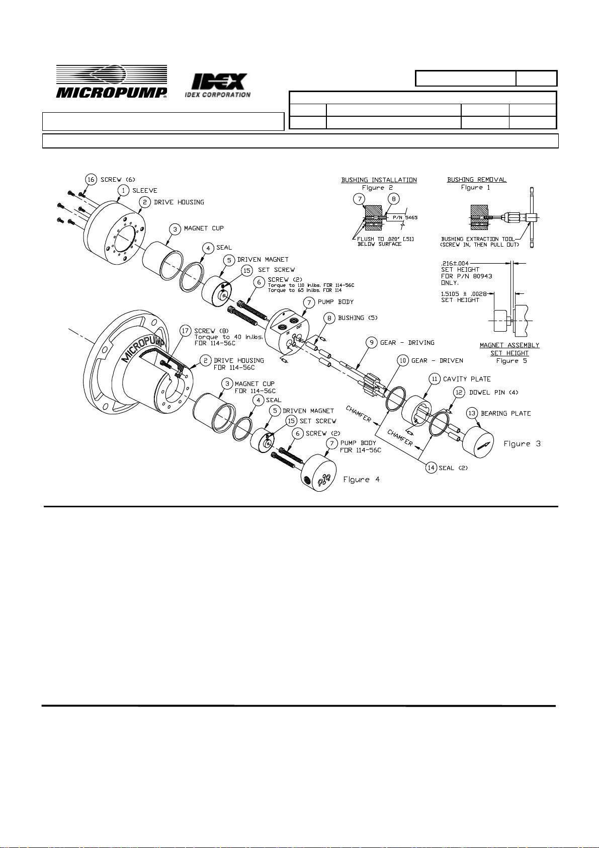
1. Remove old Bushings (8) with Extraction Tool. The use of a #8 or M4 tap with T-Handle is recommended
(See Figure 1.)
2. New Bushing installation is a press fit. Install using P/N 5465 Tool. (See Figure 2.)
MICROPUMP, INC.
A Unit of IDEX Corporation
PO Box 8975, Vancouver, WA 98668-8975 • Phone: 360/253-2008 • Fax: 360/253-8294
MICROPUMP LIMITED
A Subsidiary of Micropump, Inc.
Forge Close, Eaton Socon, St. Neots, Cambridgeshire, PE 19 3TP England, • Phone: (44) (0) 1480-219844 • Fax: (44) (0) 1480-476959
Page 1 of 3

PART NUMBER:
REVISION
LTR. DESCRIPTION DATE BY
C REVISED PER ECN-3951 10/31/96 D.M.S.
3. The first two Bushings should be installed into the Pump Body (7) from the gear side. These Bushings
should be inserted to .020 inch (.51 mm) below seal surface. The remaining two Bushings should be
inserted into the Pump Body from the Driven Magnet (5) side.
4. Next install Seal (14) and Dowel Pin (12) each in the Cavity Plate (11) and Bearing Plate (13). Face Seal
(14) chamfer away from O-Ring groove.
5. Assemble Gear Driving (9) and Gear Driven (10) into Pump Body (7) as shown. Then carefully assemble
Cavity Plate (11) and Bearing Plate (13) to Body (7) and Gear Assembly. Take care not to punch Seals
(14) during assembly.
6. Secure the assembly with 2 Bolts (6). Torque Bolts (6) to 65 in.lbs. on Model 114. (See Fig. 3). Torque
Bolts (6) to 110 in.lbs. on Model 114-56C. (See Fig. 4). Bolts (6) must be retorqued after one-half hour
before proceeding with assembly.
7. Place Magnet (5) on gear shaft and set height as shown. (See Fig. 5). Magnet must be free of metal chips
and must rotate without sticking.
8. Locate Seal (4) into body with chamfer facing magnet (5), place Magnet Cup (3) into Body (7). Assemble
Drive Housing Sleeve (1) and outer Drive Housing (2) over magnet cup lining up screw holes in Housing (1)
(2) and Body (7).
9. Secure assembly by evenly tightening 6 Screws (16) as shown. Torque 8 Screws (17) to 40 in.lbs.
5479
MICROPUMP, INC.
A Unit of IDEX Corporation
PO Box 8975, Vancouver, WA 98668-8975 • Phone: 360/253-2008 • Fax: 360/253-8294
MICROPUMP LIMITED
A Subsidiary of Micropump, Inc.
Forge Close, Eaton Socon, St. Neots, Cambridgeshire, PE 19 3TP England, • Phone: (44) (0) 1480-219844 • Fax: (44) (0) 1480-476959
Page 2 of 3
 Loading...